EP1535756A1 - Roulette pour meuble ou analogue - Google Patents
Roulette pour meuble ou analogue Download PDFInfo
- Publication number
- EP1535756A1 EP1535756A1 EP04292680A EP04292680A EP1535756A1 EP 1535756 A1 EP1535756 A1 EP 1535756A1 EP 04292680 A EP04292680 A EP 04292680A EP 04292680 A EP04292680 A EP 04292680A EP 1535756 A1 EP1535756 A1 EP 1535756A1
- Authority
- EP
- European Patent Office
- Prior art keywords
- axis
- sleeve
- rotation shaft
- bearing wall
- groove
- Prior art date
- Legal status (The legal status is an assumption and is not a legal conclusion. Google has not performed a legal analysis and makes no representation as to the accuracy of the status listed.)
- Granted
Links
Images
Classifications
-
- B—PERFORMING OPERATIONS; TRANSPORTING
- B60—VEHICLES IN GENERAL
- B60B—VEHICLE WHEELS; CASTORS; AXLES FOR WHEELS OR CASTORS; INCREASING WHEEL ADHESION
- B60B33/00—Castors in general ; Anti-clogging castors
- B60B33/0002—Castors in general ; Anti-clogging castors assembling to the object, e.g. furniture
- B60B33/0015—Castors in general ; Anti-clogging castors assembling to the object, e.g. furniture characterised by adaptations made to castor
- B60B33/0021—Castors in general ; Anti-clogging castors assembling to the object, e.g. furniture characterised by adaptations made to castor in the form of a mounting pin
-
- B—PERFORMING OPERATIONS; TRANSPORTING
- B60—VEHICLES IN GENERAL
- B60B—VEHICLE WHEELS; CASTORS; AXLES FOR WHEELS OR CASTORS; INCREASING WHEEL ADHESION
- B60B33/00—Castors in general ; Anti-clogging castors
- B60B33/0028—Construction of wheels; methods of assembling on axle
-
- B—PERFORMING OPERATIONS; TRANSPORTING
- B60—VEHICLES IN GENERAL
- B60B—VEHICLE WHEELS; CASTORS; AXLES FOR WHEELS OR CASTORS; INCREASING WHEEL ADHESION
- B60B33/00—Castors in general ; Anti-clogging castors
- B60B33/0036—Castors in general ; Anti-clogging castors characterised by type of wheels
- B60B33/0042—Double or twin wheels
-
- B—PERFORMING OPERATIONS; TRANSPORTING
- B60—VEHICLES IN GENERAL
- B60B—VEHICLE WHEELS; CASTORS; AXLES FOR WHEELS OR CASTORS; INCREASING WHEEL ADHESION
- B60B33/00—Castors in general ; Anti-clogging castors
- B60B33/0047—Castors in general ; Anti-clogging castors characterised by details of the rolling axle
- B60B33/0049—Castors in general ; Anti-clogging castors characterised by details of the rolling axle the rolling axle being horizontal
-
- B—PERFORMING OPERATIONS; TRANSPORTING
- B60—VEHICLES IN GENERAL
- B60B—VEHICLE WHEELS; CASTORS; AXLES FOR WHEELS OR CASTORS; INCREASING WHEEL ADHESION
- B60B33/00—Castors in general ; Anti-clogging castors
- B60B33/0047—Castors in general ; Anti-clogging castors characterised by details of the rolling axle
- B60B33/0057—Castors in general ; Anti-clogging castors characterised by details of the rolling axle the rolling axle being offset from swivel axis
-
- B—PERFORMING OPERATIONS; TRANSPORTING
- B60—VEHICLES IN GENERAL
- B60B—VEHICLE WHEELS; CASTORS; AXLES FOR WHEELS OR CASTORS; INCREASING WHEEL ADHESION
- B60B33/00—Castors in general ; Anti-clogging castors
- B60B33/006—Castors in general ; Anti-clogging castors characterised by details of the swivel mechanism
- B60B33/0065—Castors in general ; Anti-clogging castors characterised by details of the swivel mechanism characterised by details of the swivel axis
- B60B33/0068—Castors in general ; Anti-clogging castors characterised by details of the swivel mechanism characterised by details of the swivel axis the swivel axis being vertical
-
- B—PERFORMING OPERATIONS; TRANSPORTING
- B60—VEHICLES IN GENERAL
- B60B—VEHICLE WHEELS; CASTORS; AXLES FOR WHEELS OR CASTORS; INCREASING WHEEL ADHESION
- B60B33/00—Castors in general ; Anti-clogging castors
- B60B33/006—Castors in general ; Anti-clogging castors characterised by details of the swivel mechanism
- B60B33/0065—Castors in general ; Anti-clogging castors characterised by details of the swivel mechanism characterised by details of the swivel axis
- B60B33/0073—Castors in general ; Anti-clogging castors characterised by details of the swivel mechanism characterised by details of the swivel axis the swivel axis being symmetrical to wheel or wheels
-
- B—PERFORMING OPERATIONS; TRANSPORTING
- B60—VEHICLES IN GENERAL
- B60B—VEHICLE WHEELS; CASTORS; AXLES FOR WHEELS OR CASTORS; INCREASING WHEEL ADHESION
- B60B33/00—Castors in general ; Anti-clogging castors
- B60B33/0078—Castors in general ; Anti-clogging castors characterised by details of the wheel braking mechanism
- B60B33/0084—Castors in general ; Anti-clogging castors characterised by details of the wheel braking mechanism acting on axle end
-
- B—PERFORMING OPERATIONS; TRANSPORTING
- B60—VEHICLES IN GENERAL
- B60B—VEHICLE WHEELS; CASTORS; AXLES FOR WHEELS OR CASTORS; INCREASING WHEEL ADHESION
- B60B33/00—Castors in general ; Anti-clogging castors
- B60B33/0078—Castors in general ; Anti-clogging castors characterised by details of the wheel braking mechanism
- B60B33/0097—Castors in general ; Anti-clogging castors characterised by details of the wheel braking mechanism acting permanently, e.g. for increased security on low friction surfaces
-
- B—PERFORMING OPERATIONS; TRANSPORTING
- B60—VEHICLES IN GENERAL
- B60B—VEHICLE WHEELS; CASTORS; AXLES FOR WHEELS OR CASTORS; INCREASING WHEEL ADHESION
- B60B33/00—Castors in general ; Anti-clogging castors
- B60B33/02—Castors in general ; Anti-clogging castors with disengageable swivel action, i.e. comprising a swivel locking mechanism
- B60B33/021—Castors in general ; Anti-clogging castors with disengageable swivel action, i.e. comprising a swivel locking mechanism combined with braking of castor wheel
Definitions
- the present invention relates to castors for furniture or the like, which find a particularly advantageous application for the seats like chairs for example office.
- the wheels intended to be mounted on the seats can be equipped with a brake system that is not engaged when a person sits on the chair, and engages when the chair is empty.
- a wheel of this type includes a body, means for connecting the body to the furniture, for example a pivot, a bearing wall substantially defined in a first plane, means for securing the bearing wall with the body, at least one wheel, and advantageously two, having a first orifice defined according to a first axis, a rotation shaft having a complementary section of the orifice and defining a second axis, means for mounting the rotation shaft in cooperation with the bearing wall, the shaft being furthermore able to be plugged into the orifice so that the first and second axes are combined so that the wheel is pivotable about this second axis.
- Casters for furniture or the like known at present on the as those described and illustrated in the two referenced documents above, are functionally satisfactory but present the following disadvantage: the complexity of their structure implies the realization of a a relatively large number of constituent elements and an uncomfortable assembly of these elements.
- the present invention therefore aims to achieve a wheel for furniture or the like, which largely overcomes the disadvantages of known rollers of the prior art, in particular the disadvantage mentioned above.
- the wheel also comprises a second oblong breakthrough made in the second branch and so substantially symmetrical to the first relative to the first plane.
- the object of the invention comprises "at least one" element having a given function
- the described embodiment may include several of these elements.
- the embodiments of the object according to the invention such illustrated with several elements of identical function and if, in the description, it is not specified that the object according to this invention obligatorily include a particular number of these elements, the object of the invention may be defined as having "at least one" of these elements.
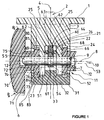
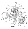
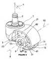
- the present invention relates, with reference to the three numbered figures 1 to 3, a furniture wheel or the like.
- This roulette has a body 1 whose shape in itself is well known in the field, means 2 for connecting the body to the furniture, by example a pivot as illustrated more particularly in Figure 3, or any other detachable attachment means or not.
- each wheel has a orifice 12 defined along a first axis 8.
- the wheel also has a rotation shaft 9, generally made of metal or the like, having a complementary section of the orifice 12, this rotation 9 defining a second axis 10, and means 11 for mounting the shaft of rotation 9 in cooperation with the bearing wall 3.
- This rotation shaft 9 is furthermore suitable for being plugged, preferably in force, into the orifice 12 of each wheel 6, 7 so that the first and second axes 8, 10 are combined for that the wheel or wheels 6, 7 are able to pivot about this second axis 10.
- the bearing wall 3 is constituted by a first bearing wall portion 21 in the general form of tuning fork, defining a groove 22 bordered by two branches 23, 24 integral a sole 25 defining the bottom 26 of the groove 22, the two branches being located in planes substantially parallel to the foreground 4, and a second bearing wall portion 31 having a base 32 and an integral tenon 33 of the base 32, this tenon having a shape substantially at least partially complementary to the groove 22 so that it can be plugged into this groove.
- the means 5 for securing the bearing wall 3 with the body 1 they are constituted by means for securing the first part of the wall of bearing 21 with the body.
- these means 5 are in fact constituted by the fact that the body 1 and the first wall part of bearing 21 are made in one piece, for example by molding a material plastic or the like.
- the means 11 defined above for mounting the rotation shaft 9 in cooperation with the bearing wall 3 are constituted by at least one first oblong breakthrough made in a branch of the first bearing wall portion 21, and very advantageously two first and second oblong holes 51, 52, as illustrated on the figures, made respectively in the two branches 23, 24, and a third oblong piercing 54 made in the post 33.
- the three oblong holes 51, 52, 54 have a cross section substantially equal to or slightly greater than the section of the tree of rotation 9 and a longitudinal section greater than the section of this same tree.
- the length of the longitudinal section of these three breakthroughs will be defined below.
- they are arranged respectively in the two branches 23, 24 and in the stud 33 so that all three are centered on a third axis 53 substantially perpendicular to the first plane 4, when the tenon 33 is plugged into the groove 22, the rotation shaft can thus cross from side to part of the bearing wall 3 so that the second axis 10 is substantially parallel to the third axis 53 and that it can be plugged in by a 55 of its ends 55, 56 in the orifice 12 of at least one of the two wheels.
- the rotation shaft is plugged by its two ends in the orifices 12 of the two wheels 6, 7.
- the rotation shaft 9 can thus pivot about its axis 10 and translate perpendicular to this axis by describing the entire length portion of the longitudinal section common to the three breakthroughs, for the purpose to be stipulated below.
- the wheel also comprises means 60 for exerting an elastic thrust force between the first bearing wall portion 21 and the rotation shaft 9.
- These means 60 comprise advantageously a fourth breakthrough 61 made in the post 33, between the face 68 of the tenon turned towards the bottom 26 of the groove 22 and the third breakthrough 54, this fourth breakthrough 61 being made along a fourth axis 62 substantially perpendicular to the third axis 53, and a spring 63 shown schematically in Figure 1 and in perspective in Figure 2.
- the spring 63 is disposed in the fourth breakthrough 61 following the fourth axis 62, so that a first 64 of its ends 64, 65 cooperates with the bottom 26 of the groove 22 and that its other second end 65 cooperates with friction with the portion of the side wall of the rotation shaft 9 being in the third breakthrough 54.
- the second end 65 of the spring 63 frictionally engages with the portion of the side wall of the shaft of rotation 9 by means of a friction pad 66 slidably mounted in the fourth breakthrough 61 and interposed between this second end and the side wall of the rotation shaft 9.
- Such a shoe may for example be constituted by a tip interposed between the spring 63 and the rotation shaft 9. But, advantageously, as schematically illustrated in section in Figure 1, it may be constituted by a ring or the like having a central breakthrough of a section complementary to that of the rotation shaft which passes through this ring.
- This pad may have, in addition to the advantage mentioned above, that of acting as a distributor of a lubricant, such as grease or the like, introduced into the groove 22 for the purpose which will be explained below in the description of the assembly and operation of the wheel, although such lubricant can be put only in the orifices 12 of the wheels 6, 7.
- a lubricant such as grease or the like
- the description of the roulette made above essentially refers to a wheel having at least one wheel, such as wheel 6. But it is obvious that this description must also be understood for a two-wheeled wheel 6, 7 as illustrated. Indeed, the roulette having a symmetry with respect to the plane 4, the description of a two-wheeled wheel is not specifically necessary and is deduced automatically from the description made above.
- a wheel like the wheels 6, 7 comprises, as schematically illustrated in the figures, a wheel flange 70 in form disk generally defined in a plane perpendicular to the first axis 8, a tread 71 secured to the outer edge of the wheel flange 70, a sleeve 72 integral, by a first 75 of its ends 75, 76, of the wheel flange, the sleeve projecting from the wheel flange and centered on the first axis 8.
- the wheel further comprises a circular neck 73 projecting on the outer side wall 74 of the sleeve 72 and substantially to the second end 76 of this sleeve, in a plane substantially perpendicular to the first axis 8.
- the wheel also comprises a first half-sleeve 80 substantially cylindrical revolution solidarity externally, by one of his two ends, of the side wall of one of the two branches 23, 24 of the first part of the bearing wall 21, the branch in which is made a first oblong breakthrough, for example breakthrough 51 for wheel 6 in reference in the embodiment illustrated in the figures.
- This first half-sleeve 80 is centered on the third axis 53 and the value of its inner diameter is greater to that of the outer diameter circular collar 73.
- first circular half-collar 81 secured to the other end of the first half-sleeve 80 and projecting on the side wall internal 82 of this first half-sleeve in a plane substantially perpendicular to the third axis 53, the value of the diameter of the inner edge of the first circular half-collar 81 being smaller than that of the outer diameter of the circular collar 73 but of course, greater than the diameter of the sleeve 72.
- the base 32 is constituted by at least one second substantially cylindrical half-sleeve 83 integral revolution of the tenon 33 by one of its ends, this second half-sleeve 83 being centered on the third axis 53 when the tenon 33 is totally plugged into the groove 22, its internal diameter being equal to that of the first half-sleeve 80 and greater than that of the circular collar 73.
- this second half-sleeve 83 is the symmetrical first half-sleeve 80 defined above.
- the wheel further comprises a second circular half-collar 84 integral the other end of the second half-sleeve 83 and projecting on the wall internal side 85 of this second half-sleeve in a plane substantially perpendicular to the third axis 53, the value of the diameter of the inner edge of the second circular half-collar 84 being smaller than that of the outer diameter of the circular collar 73 but of course also, greater than the diameter of the sleeve 72.
- the lengths of the longitudinal sections of the first, second and third oblong holes 51, 52, 54 are determined so that, when the post 33 is inserted into the groove 22 and a load of intensity greater than that of the elastic thrust force given by the spring 63 is applied to the body 1, the rotation shaft 9 comes into abutment against the bottom of the first and second bores 51, 52 located closest to the sole 25 (position P 1 illustrated in solid lines in Figure 1), and that when the pin 33 is plugged into the groove 22 and a lower intensity load than the elastic force of thrust given by the spring 63 is applied to the body 1 the circular collar 73 comes to rub against the inner side wall 85 of the second half-sleeve 83 ( P 2 position in broken lines in Figure 1).
- first and second breakthroughs 51, 52 respectively in the two branches 23, 24 are constituted by open openings, as can be seen more particularly in FIG. respectively leading to the ends of the branches furthest from the sole 25.
- roulette has means 5 for bonding the first and second bearing wall portions 21, 31 when the tenon 33 is plugged into the groove 22.
- These means 5 are advantageously constituted, like those illustrated in Figure 2, by at least one interlocking 90 having a male stud 91 made on one of the two elements "tenon 33" and “wall of the groove 22", and a hollow recess 92 of a shape substantially complementary to that of the lug 91, the notch 92 being made on the other of the two elements.
- the notch (or notches) 92 is realized in the wall of the groove 22, while the lug (or lugs) 91 is protruding on the post 33.
- the two wheels 6, 7 are then plugged into force respectively on the two ends 55, 56 of the rotation shaft 9 and so that the circular collar 73 of each wheel comes to stand, thanks to the length of the section longitudinal axis of the third breakthrough 54, between the circular half-collar 84 and the stud 33 of the second bearing wall portion 31.
- the spring 63 is introduced into the fourth breakthrough 61, with or without the pad 66, but advantageously with, depending on the configuration chosen which must be given to the roulette wheel.
- This first subset of elements thus constituted is presented in cooperation with the second subset which is actually advantageously made in one piece, and which includes the body 1 and the first part of bearing wall 21, so that the pin 33 is opposite the groove 22.
- the tenon is pressed into the groove 22 until the two pins 91
- the two half-collars 81, 84 are joined by their free ends and form the housing 86 in which is encased the circular collar 73.
- Such a wheel can of course be mounted in a manner known per se, on a piece of furniture, for example a chair or the like, by means of the pivot 2.
- the structural parameters of the spring 63 are defined so that, when a person does not occupy the chair, the force exerted by the spring is intense enough to push and move the rotation shaft 9 away from the sole 25.
- the circular collar 73 then rubs against the inner side wall 85 of the second half-sleeve 83, as shown in phantom at P 2 in Figure 1. Therefore, if the chair is unintentionally impacted or not, the friction of the circular collar 73 on the wall 85 prevents the wheel (or the two wheels 6, 7) from pivoting about the axis 10. The wheel is strongly braked and the wheelchair can not undergo significant movement.
- the circular collar 73 and the wall 85 therefore act as a brake preventing the chair, for example, to hit any object at risk of damaging or behaving as a dangerous obstacle.
- the rotation of the shaft 9 can be favored by a lubricant such as grease or the like initially placed in the groove 22 and / or the third breakthrough 54 and / or the wheel opening 12 and / or on the wall of the rotation shaft 9, and distributed on the wall of the shaft possibly at the medium including the pad 66.
- a lubricant such as grease or the like initially placed in the groove 22 and / or the third breakthrough 54 and / or the wheel opening 12 and / or on the wall of the rotation shaft 9, and distributed on the wall of the shaft possibly at the medium including the pad 66.
- Another advantage of the roulette wheel according to the invention fat that may accidentally be in excess in groove 22 and therefore overflow through the two breakthroughs 51 and 52, can in no way fall on the floor because it remains trapped in the bottom of housing 86 defined before. Even though the presence of a lubricant in the bottom of this housing 86 night substantially to the brake function defined above, it is avoided that tasks are produce on the floor, for example offices, which is usually covered carpet or the like.
Landscapes
- Engineering & Computer Science (AREA)
- Mechanical Engineering (AREA)
- Pivots And Pivotal Connections (AREA)
- Detergent Compositions (AREA)
- Silicates, Zeolites, And Molecular Sieves (AREA)
- Peptides Or Proteins (AREA)
- Moulding By Coating Moulds (AREA)
- Supports Or Holders For Household Use (AREA)
- Transition And Organic Metals Composition Catalysts For Addition Polymerization (AREA)
- Braking Arrangements (AREA)
- Sliding-Contact Bearings (AREA)
Abstract
Description
- une première partie de paroi de palier, ladite première partie de paroi de palier d'une forme générale en diapason définissant une rainure bordée par deux branches solidaires d'une semelle définissant le fond de ladite rainure, les deux dites branches étant situées dans des plans sensiblement parallèles au premier plan,
- une seconde partie de paroi de palier comportant une embase, et un tenon solidaire de ladite embase, ce dit tenon ayant une forme sensiblement au moins partiellement complémentaire de la rainure de façon qu'il puisse s'enficher dans ladite rainure, et
- des moyens pour lier les deux dites première et seconde parties de paroi de palier quand le tenon est enfiché dans la rainure,
- lesdits moyens pour solidariser la paroi de palier avec ledit corps étant constitués par des moyens pour solidariser ladite première partie de paroi de palier avec ledit corps, et
- lesdits moyens pour monter ledit arbre de rotation en coopération avec la
paroi de palier étant constitués par :
- au moins une première percée oblongue réalisée dans l'une première des deux branches et centrée sur un troisième axe sensiblement perpendiculaire au premier plan, et
- une troisième percée oblongue réalisée dans ledit tenon,
- lesdites deux première et troisième percées oblongues ayant une section transversale sensiblement égale à la section dudit arbre de rotation et une section longitudinale supérieure à la section de ce même dit arbre, et étant agencées respectivement dans l'une des deux dites branches et dans ledit tenon de façon qu'elles soient toutes les deux centrées sur ledit troisième axe lorsque le tenon est enfiché dans la rainure, l'arbre de rotation pouvant ainsi traverser de part en part la paroi de palier de façon que le deuxième axe soit sensiblement parallèle audit troisième axe et qu'il puisse être enfiché par une de ses extrémités dans l'orifice de la roue.
Claims (11)
- Roulette pour meuble ou analogue, comportant :caractérisée par le fait que la paroi de palier (3) est constituée par :un corps (1),des moyens (2) pour relier ledit corps au meuble,une paroi de palier (3) définie sensiblement dans un premier plan (4),des moyens (5) pour solidariser la paroi de palier (3) avec le corps (1),au moins une roue (6, 7) comportant un orifice (12) défini selon un premier axe (8),un arbre de rotation (9) ayant une section complémentaire de l'orifice (12), ledit arbre de rotation (9) définissant un deuxième axe (10), etdes moyens (11) pour monter ledit arbre de rotation (9) en coopération avec ladite paroi de palier (3), ledit arbre de rotation (9) étant en outre apte à être enfiché dans ledit orifice (12) de façon que les deux premier et deuxième axes (8, 10) soient confondus pour que la roue (6, 7) soit apte à pivoter autour du deuxième axe (10),une première partie de paroi de palier (21), ladite première partie de paroi de palier en forme générale de diapason définissant une rainure (22) bordée par deux branches (23, 24) solidaires d'une semelle (25) définissant le fond (26) de ladite rainure (22), les deux dites branches étant situées dans des plans sensiblement parallèles au premier plan (4),une seconde partie de paroi de palier (31) comportant une embase (32) et un tenon (33) solidaire de ladite embase (32), ce dit tenon ayant une forme sensiblement au moins partiellement complémentaire de la rainure (22) de façon qu'il puisse s'enficher dans ladite rainure,des moyens (40) pour lier les deux dites première et seconde parties de paroi de palier (21, 31) quand le tenon (33) est enfiché dans la rainure (22),lesdits moyens (5) pour solidariser la paroi de palier (3) avec ledit corps (1) étant constitués par des moyens pour solidariser la première partie de paroi de palier (21) avec ledit corps (1), etlesdits moyens (11) pour monter ledit arbre de rotation (9) en coopération avec la paroi de palier (3) étant constitués par :au moins une première percée oblongue (51, 52) réalisée dans l'une première des deux branches (23, 24), etune troisième percée oblongue (54) réalisée dans ledit tenon (33),lesdites première et troisième percées oblongues (51, 52, 54) ayant une section transversale sensiblement égale à la section dudit arbre de rotation (9) et une section longitudinale supérieure à la section de ce même dit arbre, et étant agencées respectivement dans la première branche (23, 24) et dans le tenon (33) de façon que, lorsque le tenon (33) est enfiché dans la rainure (22), elles soient toutes les deux centrées sur un troisième axe (53) sensiblement perpendiculaire au premier plan (4), l'arbre de rotation pouvant ainsi traverser de part en part la paroi de palier (3) de façon que le deuxième axe (10) soit sensiblement parallèle au troisième axe (53) et qu'il puisse être enfiché par une (55) de ses extrémités (55, 56) dans l'orifice (12) de la roue (6, 7).
- Roulette selon la revendication 1, caractérisée par le fait qu'elle comporte en outre une seconde percée oblongue (51, 52) réalisée dans la seconde branche (23, 24) et de façon sensiblement symétrique de la première percée oblongue par rapport audit premier plan (4).
- Roulette selon l'une des revendications 1 et 2, caractérisée par le fait qu'elle comporte des moyens (60) pour exercer une force de poussée élastique entre la première partie de paroi de palier (21) et l'arbre de rotation (9).
- Roulette selon la revendication 3, caractérisée par le fait que les moyens (60) pour exercer une force de poussée élastique entre la première partie de paroi de palier et l'arbre de rotation comportent :une quatrième percée (61) réalisée dans le tenon (33), entre la face (68) du tenon tournée vers le fond (26) de la rainure (22) et la troisième percée (54), ladite quatrième percée (61) étant réalisée suivant un quatrième axe (62) sensiblement perpendiculaire au troisième axe (53), etun ressort (63) disposé dans la quatrième percée (61), une première (64) de ses extrémités (64, 65) coopérant avec le fond (26) de la rainure (22) et sa seconde extrémité (65) coopérant par friction avec la portion de la paroi latérale de l'arbre de rotation (9) se trouvant dans la troisième percée (54) et sur le quatrième axe (62).
- Roulette selon la revendication 4, caractérisée par le fait que la seconde extrémité (65) du ressort (63) coopère par friction avec la portion de la paroi latérale de l'arbre de rotation se trouvant dans la troisième percée, au moyen d'un patin de friction (66) monté coulissant dans la quatrième percée (61) et interposé entre cette dite seconde extrémité du ressort (63) et la portion de paroi latérale de l'arbre de rotation (9) se trouvant dans la troisième percée (54).
- Roulette selon la revendication 5, caractérisée par le fait que ledit patin (66) est constitué par au moins l'un des éléments suivants : un embout, une bague comportant une percée centrale d'une section complémentaire de celle de l'arbre de rotation qui passe à travers cette bague.
- Roulette selon l'une des revendications 1 à 6, caractérisée par le fait que la roue (6, 7) comporte un flasque de roue (70) en forme générale de disque sensiblement défini dans un plan perpendiculaire au premier axe (8), une bande de roulement (71) solidaire du bord externe du dit flasque de roue (70), un manchon (72) solidaire, par une première (75) de ses extrémités (75, 76), du dit flasque de roue, ledit manchon étant en saillie sur ledit flasque de roue et centré sur le premier axe (8), ledit orifice (12) étant réalisé au moins dans ledit manchon, et un collet circulaire (73) situé en saillie sur la paroi latérale externe (74) dudit manchon (72) et sensiblement à la seconde extrémité (76) dudit manchon, dans un plan sensiblement perpendiculaire au premier axe (8).
- Roulette selon la revendication 7, caractérisée par le fait qu'elle comporte en outre un premier demi-manchon (80) sensiblement cylindrique de révolution solidaire extérieurement, par une de ses deux extrémités, de la paroi latérale de l'une des deux branches (23, 24) de la première partie de paroi de palier (21), ledit premier demi-manchon (80) étant centré sur le troisième axe (53) et son diamètre interne ayant une valeur supérieure à celle du diamètre externe du collet circulaire (73), et un premier demi-collet circulaire (81) solidaire de l'autre extrémité du premier demi-manchon (80) et formant saillie sur la paroi latérale interne (82) de ce premier demi-manchon dans un plan sensiblement perpendiculaire au troisième axe (53), la valeur du diamètre du bord interne du premier demi-collet circulaire (81) étant inférieure à celle du diamètre externe du collet circulaire (73), et que ladite embase (32) est constituée par au moins un second demi-manchon (83) sensiblement cylindrique de révolution solidaire dudit tenon (33) par l'une de ses extrémités, ce dit second demi-manchon (83) étant centré sur le troisième axe (53) quand le tenon (33) est enfiché dans la rainure (22), son diamètre interne étant égal à celui du premier demi-manchon (80) et supérieur à celui du collet circulaire (73), un second demi-collet circulaire (84) solidaire de l'autre extrémité du second demi-manchon (83) et formant saillie sur la paroi latérale interne (85) de ce second demi-manchon dans un plan sensiblement perpendiculaire au troisième axe (53), la valeur du diamètre du bord interne du second demi-collet circulaire (84) étant inférieure à celle du diamètre externe du collet circulaire (73), de façon que, lorsque l'arbre de rotation (9) est enfiché dans l'orifice (12) et que le tenon (33) est enfiché totalement et fixement dans la rainure (22), ledit collet circulaire (73) soit situé dans le logement cylindrique (86) formé et délimité par les deux demi-collets circulaires (81, 84) au contact l'un de l'autre par leurs extrémités libres, la paroi latérale externe de la branche (23, 24) portant le premier demi-manchon (80) et les deux parois latérales internes (82, 85) respectivement des premier et second demi-manchons (80, 83).
- Roulette selon les revendications 2 et 8, caractérisée par le fait que les longueurs des sections longitudinales des trois première, deuxième et troisième percées oblongues (51, 52, 54) sont déterminées de façon que, lorsqu'une charge d'intensité supérieure à celle de la force élastique de poussée est appliquée sur ledit corps (1), l'arbre de rotation (9) vienne en butée contre le fond des deux première et deuxième percées (51, 52) situé le plus proche de la semelle (25), et que, lorsqu'une charge d'intensité inférieure à celle de la force élastique de poussée est appliquée sur ledit corps (1), le collet circulaire (73) vienne en butée contre la paroi latérale interne (85) du second demi-manchon (83).
- Roulette selon l'une des revendications 2 à 9, caractérisée par le fait que les première et deuxième percées (51, 52) réalisées respectivement dans les deux branches (23, 24) sont constituées par des percées ouvertes débouchant respectivement sur les extrémités des branches les plus éloignées de la semelle (25).
- Roulette selon l'une des revendications 1 à 10, caractérisée par le fait que les moyens (5) pour lier les première et seconde parties de paroi de palier (21, 31) quand le tenon (33) est enfiché dans la rainure (22), sont constitués par au moins un emboítement (90) comportant un ergot mâle (91) réalisé sur l'un des deux éléments "tenon (33)" et "paroi de la rainure (22)", et une encoche en creux (92) d'une forme sensiblement complémentaire de celle du dit ergot (91), ladite encoche (92) étant réalisée sur l'autre des deux éléments.
Applications Claiming Priority (2)
| Application Number | Priority Date | Filing Date | Title |
|---|---|---|---|
| FR0313623 | 2003-11-21 | ||
| FR0313623A FR2862569B1 (fr) | 2003-11-21 | 2003-11-21 | Roulette pour meuble ou analogue |
Publications (2)
| Publication Number | Publication Date |
|---|---|
| EP1535756A1 true EP1535756A1 (fr) | 2005-06-01 |
| EP1535756B1 EP1535756B1 (fr) | 2008-02-20 |
Family
ID=34451661
Family Applications (1)
| Application Number | Title | Priority Date | Filing Date |
|---|---|---|---|
| EP04292680A Expired - Lifetime EP1535756B1 (fr) | 2003-11-21 | 2004-11-12 | Roulette pour meuble ou analogue |
Country Status (5)
| Country | Link |
|---|---|
| US (1) | US7200895B2 (fr) |
| EP (1) | EP1535756B1 (fr) |
| AT (1) | ATE386648T1 (fr) |
| DE (1) | DE602004011881D1 (fr) |
| FR (1) | FR2862569B1 (fr) |
Cited By (2)
| Publication number | Priority date | Publication date | Assignee | Title |
|---|---|---|---|---|
| WO2006117128A1 (fr) | 2005-04-29 | 2006-11-09 | Gross + Froelich Gmbh & Co. Kg | Roulette de guidage a roues jumelees |
| CN109296903A (zh) * | 2018-11-02 | 2019-02-01 | 浙江厚达智能科技股份有限公司 | 隔振式光纤盘扫码机顶升旋转装置 |
Families Citing this family (14)
| Publication number | Priority date | Publication date | Assignee | Title |
|---|---|---|---|---|
| FR2895702B1 (fr) * | 2005-12-29 | 2008-02-29 | Bruandet Sa Sa | Roulette pour meuble ou analogue |
| US20080020084A1 (en) * | 2006-07-19 | 2008-01-24 | Piepenburg Robert E | Turntable apparatus for use in trimming unfired pottery, and method of using same |
| DE102006049725A1 (de) * | 2006-10-21 | 2008-04-30 | Gross + Froelich Gmbh & Co. Kg | Lenkrolle mit hochfestem Achsträger |
| US9027204B2 (en) | 2007-05-07 | 2015-05-12 | Jacob Holtz Company | Casters having weight transferring tab |
| CN101715311B (zh) * | 2007-05-07 | 2013-02-06 | 雅各布霍尔茨公司 | 带有重量传递突出部的轮脚 |
| USD602769S1 (en) | 2008-05-05 | 2009-10-27 | Jacob Holtz Company | Caster |
| ITBO20110640A1 (it) * | 2011-11-09 | 2013-05-10 | Emilsider Meccanica | Ruota gemellata auto-orientabile con gruppo frenante perfezionato |
| US9340069B1 (en) * | 2015-01-07 | 2016-05-17 | Wen-Chin Cheng | Wheel device |
| DE102016123080A1 (de) * | 2016-11-30 | 2018-05-30 | Gross + Froelich Gmbh & Co. Kg | Rolle mit Bremsvorrichtung |
| CN206501650U (zh) * | 2016-12-14 | 2017-09-19 | 马展雄 | 压力式刹车轮 |
| US10759221B1 (en) * | 2019-05-08 | 2020-09-01 | Po-Chuan Tsai | Caster device |
| US20240367704A1 (en) * | 2023-05-03 | 2024-11-07 | Elmatek International Corp. | Castor with pressure brake device |
| CN119116590A (zh) * | 2023-06-13 | 2024-12-13 | 广力达企业有限公司 | 脚轮装置 |
| CN118651006A (zh) * | 2024-08-20 | 2024-09-17 | 长安绿电科技有限公司 | 具有移动功能的储能电源 |
Citations (5)
| Publication number | Priority date | Publication date | Assignee | Title |
|---|---|---|---|---|
| US4821369A (en) * | 1986-09-16 | 1989-04-18 | Guy-Raymond Engineering Company Ltd. | Castors braked either in response to a load or to the absence of a load |
| US5355550A (en) * | 1993-10-19 | 1994-10-18 | Yang Su Hua | Pivoting castor |
| EP0645262A1 (fr) | 1993-09-24 | 1995-03-29 | EMILSIDER MECCANICA S.p.A. | Dispositif contre la pénétration d'impuretés et permettant l'application et la rétention de lubrifiant dans des roulettes doubles à pivot à auto-orientation |
| US6092262A (en) * | 1998-10-01 | 2000-07-25 | Lin; Arthur | Non-skid wheel brake mechanism |
| EP1110757A2 (fr) | 1999-12-24 | 2001-06-27 | EMILSIDER MECCANICA S.p.A. | Roulette double à pivot comportant une paire de roues coaxiales |
Family Cites Families (15)
| Publication number | Priority date | Publication date | Assignee | Title |
|---|---|---|---|---|
| US3914821A (en) * | 1974-07-19 | 1975-10-28 | British Castors Ltd | Castors |
| IT1070548B (it) * | 1976-12-29 | 1985-03-29 | Emilsider Meccanica | Ruota autoorientabile a rotelle gemelle e con carenatura metallica |
| DE2746891C3 (de) * | 1977-10-19 | 1980-06-12 | Paul Vom Stein & Co, 5632 Wermelskirchen | Lenkrolle für Sitzmöbel |
| IT1087044B (it) * | 1977-11-03 | 1985-05-31 | Ferrari Agostino & C S N C | Ruota autoorientabile,in particolare per sedie |
| IT1106682B (it) * | 1978-06-26 | 1985-11-18 | Emilsider Meccanica | Ruota autoorientabile con rotelle gemelle |
| ZA81780B (en) * | 1980-02-12 | 1982-03-31 | British Castors Ltd | Castor with braking means |
| JPS57147948A (en) * | 1981-03-09 | 1982-09-13 | Sugatsune Ind Co Ltd | Caster stopper |
| US4550808A (en) * | 1984-01-30 | 1985-11-05 | Illinois Tool Works Inc. | Brake for twin wheel casters |
| US4649595A (en) * | 1985-10-02 | 1987-03-17 | Shepherd Products U.S. Inc. | Resiliently mounted caster having a pivotally mounted inner body member |
| JPH03266702A (ja) * | 1990-03-15 | 1991-11-27 | Skancaster As | 自動ブレーキ装置付キャスター |
| US5368133A (en) * | 1993-09-17 | 1994-11-29 | Yang; Sung-Wang | Brake system for roller casters |
| JP2885083B2 (ja) * | 1994-08-31 | 1999-04-19 | 双葉金属工業株式会社 | 制動機構を有するキャスター |
| US5617934A (en) * | 1996-05-14 | 1997-04-08 | Yang; Sung-Wang | Brake mechanism of castor |
| JPH10138703A (ja) * | 1996-11-12 | 1998-05-26 | Koizumi:Kk | オートブレーキキャスター |
| JP4133794B2 (ja) * | 2003-12-22 | 2008-08-13 | 株式会社内外 | ストッパ付きキャスター |
-
2003
- 2003-11-21 FR FR0313623A patent/FR2862569B1/fr not_active Expired - Fee Related
-
2004
- 2004-11-12 DE DE602004011881T patent/DE602004011881D1/de not_active Expired - Lifetime
- 2004-11-12 AT AT04292680T patent/ATE386648T1/de not_active IP Right Cessation
- 2004-11-12 EP EP04292680A patent/EP1535756B1/fr not_active Expired - Lifetime
- 2004-11-22 US US10/993,361 patent/US7200895B2/en not_active Expired - Fee Related
Patent Citations (6)
| Publication number | Priority date | Publication date | Assignee | Title |
|---|---|---|---|---|
| US4821369A (en) * | 1986-09-16 | 1989-04-18 | Guy-Raymond Engineering Company Ltd. | Castors braked either in response to a load or to the absence of a load |
| EP0645262A1 (fr) | 1993-09-24 | 1995-03-29 | EMILSIDER MECCANICA S.p.A. | Dispositif contre la pénétration d'impuretés et permettant l'application et la rétention de lubrifiant dans des roulettes doubles à pivot à auto-orientation |
| US5355550A (en) * | 1993-10-19 | 1994-10-18 | Yang Su Hua | Pivoting castor |
| US6092262A (en) * | 1998-10-01 | 2000-07-25 | Lin; Arthur | Non-skid wheel brake mechanism |
| EP1110757A2 (fr) | 1999-12-24 | 2001-06-27 | EMILSIDER MECCANICA S.p.A. | Roulette double à pivot comportant une paire de roues coaxiales |
| US6615448B2 (en) * | 1999-12-24 | 2003-09-09 | Emilsider Meccanica S.P.A. | Self-orientating twin castor of the type comprising a pair of coaxial wheels |
Cited By (3)
| Publication number | Priority date | Publication date | Assignee | Title |
|---|---|---|---|---|
| WO2006117128A1 (fr) | 2005-04-29 | 2006-11-09 | Gross + Froelich Gmbh & Co. Kg | Roulette de guidage a roues jumelees |
| US8015664B2 (en) | 2005-04-29 | 2011-09-13 | Gross & Froelich Gmbh & Co. Kg | Twin-wheel caster |
| CN109296903A (zh) * | 2018-11-02 | 2019-02-01 | 浙江厚达智能科技股份有限公司 | 隔振式光纤盘扫码机顶升旋转装置 |
Also Published As
| Publication number | Publication date |
|---|---|
| FR2862569B1 (fr) | 2006-02-17 |
| US7200895B2 (en) | 2007-04-10 |
| FR2862569A1 (fr) | 2005-05-27 |
| DE602004011881D1 (de) | 2008-04-03 |
| ATE386648T1 (de) | 2008-03-15 |
| EP1535756B1 (fr) | 2008-02-20 |
| US20050108851A1 (en) | 2005-05-26 |
Similar Documents
| Publication | Publication Date | Title |
|---|---|---|
| EP1535756B1 (fr) | Roulette pour meuble ou analogue | |
| CA2275977C (fr) | Noix d'articulation pour accoudoir de fauteuil d'handicape et fauteuil en faisant application | |
| EP3081466B1 (fr) | Ensemble d'elements permettant de constituer deux sortes d'engins a roues pour enfants | |
| EP1281878A1 (fr) | Axe de liaison pivot entre deux pièces | |
| WO1999065355A1 (fr) | Chaine ornementale composee d'elements successifs ayant chacun une forme generale spherique | |
| EP0661938B1 (fr) | Fermoir du type a boucle deployante pour bracelet | |
| FR2758471A1 (fr) | Patin a roulettes en ligne muni d'un frein agissant sur les roulettes | |
| WO2004108516A1 (fr) | Dispositif de fixation en porte-a-faux d’une roue de velo sur un cadre avec un mecanisme de serrage rapide | |
| FR2850079A1 (fr) | Pedale cycliste de securite | |
| FR2984842A3 (fr) | Pedale de bicyclette du type a enclenchement et declenchement automatiques. | |
| EP0382584B1 (fr) | Roulette pour pied de meuble ou analogue permettant la décharge de l'électricité statique | |
| EP2476335A1 (fr) | Bijou modulaire | |
| EP3724000B1 (fr) | Roulette pour meuble | |
| WO2016156620A1 (fr) | Dispositif amovible de stabilisation d'un fauteuil roulant ou similaire | |
| FR3009700A1 (fr) | Pivot pour roulette et meuble comportant un tel pivot | |
| WO2006136691A2 (fr) | Dispositif de montage d'un patin d'appui au sol sur un baton de marche | |
| EP2379183A1 (fr) | Raquette a neige a cale de montee | |
| EP1541018B1 (fr) | Piquets de cloture associes par auto-assemblage | |
| FR2964598A1 (fr) | Roulette pour meuble ou analogue avec moyens de blocage | |
| EP0838372A1 (fr) | Dispositif d'aide au chargement d'un coffre de véhicule automobile | |
| WO2004002596A1 (fr) | Structure constituee d'une enveloppe souple mise en forme par un rembourrage interne, munie de moyens d'agrementation en produit odoriferant | |
| EP1582315A1 (fr) | Ciseaux à ressort d'ouverture | |
| FR2849750A1 (fr) | Bouton a decor interchangeable | |
| EP3007579B1 (fr) | Dispositif pour la fixation amovible d'un élément à un article | |
| FR3130169A1 (fr) | Fixation pour chaussure sur raquette a neige |
Legal Events
| Date | Code | Title | Description |
|---|---|---|---|
| PUAI | Public reference made under article 153(3) epc to a published international application that has entered the european phase |
Free format text: ORIGINAL CODE: 0009012 |
|
| AK | Designated contracting states |
Kind code of ref document: A1 Designated state(s): AT BE BG CH CY CZ DE DK EE ES FI FR GB GR HU IE IS IT LI LU MC NL PL PT RO SE SI SK TR |
|
| AX | Request for extension of the european patent |
Extension state: AL HR LT LV MK YU |
|
| 17P | Request for examination filed |
Effective date: 20051123 |
|
| AKX | Designation fees paid |
Designated state(s): AT BE BG CH CY CZ DE DK EE ES FI FR GB GR HU IE IS IT LI LU MC NL PL PT RO SE SI SK TR |
|
| GRAP | Despatch of communication of intention to grant a patent |
Free format text: ORIGINAL CODE: EPIDOSNIGR1 |
|
| GRAS | Grant fee paid |
Free format text: ORIGINAL CODE: EPIDOSNIGR3 |
|
| GRAA | (expected) grant |
Free format text: ORIGINAL CODE: 0009210 |
|
| AK | Designated contracting states |
Kind code of ref document: B1 Designated state(s): AT BE BG CH CY CZ DE DK EE ES FI FR GB GR HU IE IS IT LI LU MC NL PL PT RO SE SI SK TR |
|
| REG | Reference to a national code |
Ref country code: GB Ref legal event code: FG4D Free format text: NOT ENGLISH |
|
| REG | Reference to a national code |
Ref country code: CH Ref legal event code: EP |
|
| REG | Reference to a national code |
Ref country code: IE Ref legal event code: FG4D Free format text: LANGUAGE OF EP DOCUMENT: FRENCH |
|
| REF | Corresponds to: |
Ref document number: 602004011881 Country of ref document: DE Date of ref document: 20080403 Kind code of ref document: P |
|
| PG25 | Lapsed in a contracting state [announced via postgrant information from national office to epo] |
Ref country code: FI Free format text: LAPSE BECAUSE OF FAILURE TO SUBMIT A TRANSLATION OF THE DESCRIPTION OR TO PAY THE FEE WITHIN THE PRESCRIBED TIME-LIMIT Effective date: 20080220 Ref country code: IS Free format text: LAPSE BECAUSE OF FAILURE TO SUBMIT A TRANSLATION OF THE DESCRIPTION OR TO PAY THE FEE WITHIN THE PRESCRIBED TIME-LIMIT Effective date: 20080620 Ref country code: ES Free format text: LAPSE BECAUSE OF FAILURE TO SUBMIT A TRANSLATION OF THE DESCRIPTION OR TO PAY THE FEE WITHIN THE PRESCRIBED TIME-LIMIT Effective date: 20080531 |
|
| NLV1 | Nl: lapsed or annulled due to failure to fulfill the requirements of art. 29p and 29m of the patents act | ||
| PG25 | Lapsed in a contracting state [announced via postgrant information from national office to epo] |
Ref country code: AT Free format text: LAPSE BECAUSE OF FAILURE TO SUBMIT A TRANSLATION OF THE DESCRIPTION OR TO PAY THE FEE WITHIN THE PRESCRIBED TIME-LIMIT Effective date: 20080220 |
|
| PG25 | Lapsed in a contracting state [announced via postgrant information from national office to epo] |
Ref country code: SI Free format text: LAPSE BECAUSE OF FAILURE TO SUBMIT A TRANSLATION OF THE DESCRIPTION OR TO PAY THE FEE WITHIN THE PRESCRIBED TIME-LIMIT Effective date: 20080220 Ref country code: PL Free format text: LAPSE BECAUSE OF FAILURE TO SUBMIT A TRANSLATION OF THE DESCRIPTION OR TO PAY THE FEE WITHIN THE PRESCRIBED TIME-LIMIT Effective date: 20080220 |
|
| REG | Reference to a national code |
Ref country code: IE Ref legal event code: FD4D |
|
| PG25 | Lapsed in a contracting state [announced via postgrant information from national office to epo] |
Ref country code: DK Free format text: LAPSE BECAUSE OF FAILURE TO SUBMIT A TRANSLATION OF THE DESCRIPTION OR TO PAY THE FEE WITHIN THE PRESCRIBED TIME-LIMIT Effective date: 20080220 Ref country code: CZ Free format text: LAPSE BECAUSE OF FAILURE TO SUBMIT A TRANSLATION OF THE DESCRIPTION OR TO PAY THE FEE WITHIN THE PRESCRIBED TIME-LIMIT Effective date: 20080220 Ref country code: NL Free format text: LAPSE BECAUSE OF FAILURE TO SUBMIT A TRANSLATION OF THE DESCRIPTION OR TO PAY THE FEE WITHIN THE PRESCRIBED TIME-LIMIT Effective date: 20080220 Ref country code: PT Free format text: LAPSE BECAUSE OF FAILURE TO SUBMIT A TRANSLATION OF THE DESCRIPTION OR TO PAY THE FEE WITHIN THE PRESCRIBED TIME-LIMIT Effective date: 20080721 Ref country code: SE Free format text: LAPSE BECAUSE OF FAILURE TO SUBMIT A TRANSLATION OF THE DESCRIPTION OR TO PAY THE FEE WITHIN THE PRESCRIBED TIME-LIMIT Effective date: 20080520 Ref country code: SK Free format text: LAPSE BECAUSE OF FAILURE TO SUBMIT A TRANSLATION OF THE DESCRIPTION OR TO PAY THE FEE WITHIN THE PRESCRIBED TIME-LIMIT Effective date: 20080220 Ref country code: IE Free format text: LAPSE BECAUSE OF FAILURE TO SUBMIT A TRANSLATION OF THE DESCRIPTION OR TO PAY THE FEE WITHIN THE PRESCRIBED TIME-LIMIT Effective date: 20080220 |
|
| PG25 | Lapsed in a contracting state [announced via postgrant information from national office to epo] |
Ref country code: RO Free format text: LAPSE BECAUSE OF FAILURE TO SUBMIT A TRANSLATION OF THE DESCRIPTION OR TO PAY THE FEE WITHIN THE PRESCRIBED TIME-LIMIT Effective date: 20080220 |
|
| PLBE | No opposition filed within time limit |
Free format text: ORIGINAL CODE: 0009261 |
|
| STAA | Information on the status of an ep patent application or granted ep patent |
Free format text: STATUS: NO OPPOSITION FILED WITHIN TIME LIMIT |
|
| 26N | No opposition filed |
Effective date: 20081121 |
|
| PG25 | Lapsed in a contracting state [announced via postgrant information from national office to epo] |
Ref country code: DE Free format text: LAPSE BECAUSE OF FAILURE TO SUBMIT A TRANSLATION OF THE DESCRIPTION OR TO PAY THE FEE WITHIN THE PRESCRIBED TIME-LIMIT Effective date: 20080521 |
|
| PG25 | Lapsed in a contracting state [announced via postgrant information from national office to epo] |
Ref country code: EE Free format text: LAPSE BECAUSE OF FAILURE TO SUBMIT A TRANSLATION OF THE DESCRIPTION OR TO PAY THE FEE WITHIN THE PRESCRIBED TIME-LIMIT Effective date: 20080220 Ref country code: BG Free format text: LAPSE BECAUSE OF FAILURE TO SUBMIT A TRANSLATION OF THE DESCRIPTION OR TO PAY THE FEE WITHIN THE PRESCRIBED TIME-LIMIT Effective date: 20080520 |
|
| BERE | Be: lapsed |
Owner name: BRUANDET S.A. Effective date: 20081130 |
|
| PG25 | Lapsed in a contracting state [announced via postgrant information from national office to epo] |
Ref country code: MC Free format text: LAPSE BECAUSE OF NON-PAYMENT OF DUE FEES Effective date: 20081130 |
|
| REG | Reference to a national code |
Ref country code: CH Ref legal event code: PL |
|
| GBPC | Gb: european patent ceased through non-payment of renewal fee |
Effective date: 20081112 |
|
| PG25 | Lapsed in a contracting state [announced via postgrant information from national office to epo] |
Ref country code: CY Free format text: LAPSE BECAUSE OF FAILURE TO SUBMIT A TRANSLATION OF THE DESCRIPTION OR TO PAY THE FEE WITHIN THE PRESCRIBED TIME-LIMIT Effective date: 20080220 |
|
| PG25 | Lapsed in a contracting state [announced via postgrant information from national office to epo] |
Ref country code: IT Free format text: LAPSE BECAUSE OF FAILURE TO SUBMIT A TRANSLATION OF THE DESCRIPTION OR TO PAY THE FEE WITHIN THE PRESCRIBED TIME-LIMIT Effective date: 20080220 |
|
| PG25 | Lapsed in a contracting state [announced via postgrant information from national office to epo] |
Ref country code: BE Free format text: LAPSE BECAUSE OF NON-PAYMENT OF DUE FEES Effective date: 20081130 |
|
| PG25 | Lapsed in a contracting state [announced via postgrant information from national office to epo] |
Ref country code: LI Free format text: LAPSE BECAUSE OF NON-PAYMENT OF DUE FEES Effective date: 20081130 Ref country code: CH Free format text: LAPSE BECAUSE OF NON-PAYMENT OF DUE FEES Effective date: 20081130 |
|
| PG25 | Lapsed in a contracting state [announced via postgrant information from national office to epo] |
Ref country code: GB Free format text: LAPSE BECAUSE OF NON-PAYMENT OF DUE FEES Effective date: 20081112 |
|
| PG25 | Lapsed in a contracting state [announced via postgrant information from national office to epo] |
Ref country code: HU Free format text: LAPSE BECAUSE OF FAILURE TO SUBMIT A TRANSLATION OF THE DESCRIPTION OR TO PAY THE FEE WITHIN THE PRESCRIBED TIME-LIMIT Effective date: 20080821 Ref country code: LU Free format text: LAPSE BECAUSE OF NON-PAYMENT OF DUE FEES Effective date: 20081112 |
|
| PG25 | Lapsed in a contracting state [announced via postgrant information from national office to epo] |
Ref country code: TR Free format text: LAPSE BECAUSE OF FAILURE TO SUBMIT A TRANSLATION OF THE DESCRIPTION OR TO PAY THE FEE WITHIN THE PRESCRIBED TIME-LIMIT Effective date: 20080220 |
|
| PG25 | Lapsed in a contracting state [announced via postgrant information from national office to epo] |
Ref country code: GR Free format text: LAPSE BECAUSE OF FAILURE TO SUBMIT A TRANSLATION OF THE DESCRIPTION OR TO PAY THE FEE WITHIN THE PRESCRIBED TIME-LIMIT Effective date: 20080521 |
|
| PGFP | Annual fee paid to national office [announced via postgrant information from national office to epo] |
Ref country code: FR Payment date: 20131127 Year of fee payment: 10 |
|
| REG | Reference to a national code |
Ref country code: FR Ref legal event code: ST Effective date: 20150731 |
|
| PG25 | Lapsed in a contracting state [announced via postgrant information from national office to epo] |
Ref country code: FR Free format text: LAPSE BECAUSE OF NON-PAYMENT OF DUE FEES Effective date: 20141201 |