EP1535697A1 - Method and device for processing inside of transparent material - Google Patents

Method and device for processing inside of transparent material Download PDF

Info

Publication number
EP1535697A1
EP1535697A1 EP03755268A EP03755268A EP1535697A1 EP 1535697 A1 EP1535697 A1 EP 1535697A1 EP 03755268 A EP03755268 A EP 03755268A EP 03755268 A EP03755268 A EP 03755268A EP 1535697 A1 EP1535697 A1 EP 1535697A1
Authority
EP
European Patent Office
Prior art keywords
laser light
shape
femtosecond laser
transparent material
cross
Prior art date
Legal status (The legal status is an assumption and is not a legal conclusion. Google has not performed a legal analysis and makes no representation as to the accuracy of the status listed.)
Withdrawn
Application number
EP03755268A
Other languages
German (de)
French (fr)
Other versions
EP1535697A4 (en
Inventor
Koji c/o RIKEN SUGIOKA
Ya c/o RIKEN CHENG
Katsumi c/o RIKEN MIDORIKAWA
Current Assignee (The listed assignees may be inaccurate. Google has not performed a legal analysis and makes no representation or warranty as to the accuracy of the list.)
RIKEN
Original Assignee
RIKEN
Priority date (The priority date is an assumption and is not a legal conclusion. Google has not performed a legal analysis and makes no representation as to the accuracy of the date listed.)
Filing date
Publication date
Application filed by RIKEN filed Critical RIKEN
Publication of EP1535697A1 publication Critical patent/EP1535697A1/en
Publication of EP1535697A4 publication Critical patent/EP1535697A4/en
Withdrawn legal-status Critical Current

Links

Images

Classifications

    • CCHEMISTRY; METALLURGY
    • C03GLASS; MINERAL OR SLAG WOOL
    • C03CCHEMICAL COMPOSITION OF GLASSES, GLAZES OR VITREOUS ENAMELS; SURFACE TREATMENT OF GLASS; SURFACE TREATMENT OF FIBRES OR FILAMENTS MADE FROM GLASS, MINERALS OR SLAGS; JOINING GLASS TO GLASS OR OTHER MATERIALS
    • C03C23/00Other surface treatment of glass not in the form of fibres or filaments
    • C03C23/0005Other surface treatment of glass not in the form of fibres or filaments by irradiation
    • C03C23/0025Other surface treatment of glass not in the form of fibres or filaments by irradiation by a laser beam
    • BPERFORMING OPERATIONS; TRANSPORTING
    • B23MACHINE TOOLS; METAL-WORKING NOT OTHERWISE PROVIDED FOR
    • B23KSOLDERING OR UNSOLDERING; WELDING; CLADDING OR PLATING BY SOLDERING OR WELDING; CUTTING BY APPLYING HEAT LOCALLY, e.g. FLAME CUTTING; WORKING BY LASER BEAM
    • B23K26/00Working by laser beam, e.g. welding, cutting or boring
    • B23K26/02Positioning or observing the workpiece, e.g. with respect to the point of impact; Aligning, aiming or focusing the laser beam
    • B23K26/06Shaping the laser beam, e.g. by masks or multi-focusing
    • B23K26/062Shaping the laser beam, e.g. by masks or multi-focusing by direct control of the laser beam
    • B23K26/0622Shaping the laser beam, e.g. by masks or multi-focusing by direct control of the laser beam by shaping pulses
    • B23K26/0624Shaping the laser beam, e.g. by masks or multi-focusing by direct control of the laser beam by shaping pulses using ultrashort pulses, i.e. pulses of 1 ns or less
    • BPERFORMING OPERATIONS; TRANSPORTING
    • B23MACHINE TOOLS; METAL-WORKING NOT OTHERWISE PROVIDED FOR
    • B23KSOLDERING OR UNSOLDERING; WELDING; CLADDING OR PLATING BY SOLDERING OR WELDING; CUTTING BY APPLYING HEAT LOCALLY, e.g. FLAME CUTTING; WORKING BY LASER BEAM
    • B23K26/00Working by laser beam, e.g. welding, cutting or boring
    • B23K26/02Positioning or observing the workpiece, e.g. with respect to the point of impact; Aligning, aiming or focusing the laser beam
    • B23K26/06Shaping the laser beam, e.g. by masks or multi-focusing
    • B23K26/064Shaping the laser beam, e.g. by masks or multi-focusing by means of optical elements, e.g. lenses, mirrors or prisms
    • B23K26/066Shaping the laser beam, e.g. by masks or multi-focusing by means of optical elements, e.g. lenses, mirrors or prisms by using masks
    • BPERFORMING OPERATIONS; TRANSPORTING
    • B23MACHINE TOOLS; METAL-WORKING NOT OTHERWISE PROVIDED FOR
    • B23KSOLDERING OR UNSOLDERING; WELDING; CLADDING OR PLATING BY SOLDERING OR WELDING; CUTTING BY APPLYING HEAT LOCALLY, e.g. FLAME CUTTING; WORKING BY LASER BEAM
    • B23K26/00Working by laser beam, e.g. welding, cutting or boring
    • B23K26/50Working by transmitting the laser beam through or within the workpiece
    • B23K26/53Working by transmitting the laser beam through or within the workpiece for modifying or reforming the material inside the workpiece, e.g. for producing break initiation cracks
    • BPERFORMING OPERATIONS; TRANSPORTING
    • B23MACHINE TOOLS; METAL-WORKING NOT OTHERWISE PROVIDED FOR
    • B23KSOLDERING OR UNSOLDERING; WELDING; CLADDING OR PLATING BY SOLDERING OR WELDING; CUTTING BY APPLYING HEAT LOCALLY, e.g. FLAME CUTTING; WORKING BY LASER BEAM
    • B23K26/00Working by laser beam, e.g. welding, cutting or boring
    • B23K26/50Working by transmitting the laser beam through or within the workpiece
    • B23K26/55Working by transmitting the laser beam through or within the workpiece for creating voids inside the workpiece, e.g. for forming flow passages or flow patterns
    • CCHEMISTRY; METALLURGY
    • C03GLASS; MINERAL OR SLAG WOOL
    • C03CCHEMICAL COMPOSITION OF GLASSES, GLAZES OR VITREOUS ENAMELS; SURFACE TREATMENT OF GLASS; SURFACE TREATMENT OF FIBRES OR FILAMENTS MADE FROM GLASS, MINERALS OR SLAGS; JOINING GLASS TO GLASS OR OTHER MATERIALS
    • C03C4/00Compositions for glass with special properties
    • C03C4/04Compositions for glass with special properties for photosensitive glass

Definitions

  • the present invention relates to a method and a device for processing the inside of a transparent material, more specifically to a method and a device for processing the inside of a transparent material, which is preferably used in performing processing such as modification and working of the inside of the transparent material with respect to laser light of femtosecond laser light having the pulse width of a 10 -13 second order.
  • femtosecond laser light which has the pulse width of a 10 -13 second order as a laser light source of a sub-picosecond or less.
  • femtosecond laser light being laser light that is emitted from such femtosecond laser, which is a femtosecond laser having the pulse width of about 100 to 150 femtoseconds
  • laser light that is emitted from femtosecond laser shall be referred to as "femtosecond laser light” in this specification
  • femtosecond laser light is focused on the inside of a transparent material with respect to the femtosecond laser light (a transparent material with respect to predetermined femtosecond laser light shall be appropriately referred to simply as a "transparent material” in this specification) via a lens
  • a transparent material with respect to predetermined femtosecond laser light shall be appropriately referred to simply as a "transparent material” in this specification
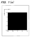
  • the spatial intensity distribution in the direction parallel to the advance direction of the beam of femtosecond laser light at the focal spot should be the intensity distribution of a lengthwise elliptical shape extending in the advance direction of the beam of femtosecond laser light, as shown in Fig. 1(a).
  • the processed shape such as a modified shape and a worked shape inside the transparent material became the lengthwise elliptical shape extending in the advance direction of the beam of femtosecond laser light by suffering from the spatial intensity distribution in the direction parallel to the advance direction of the beam of femtosecond laser light at the focal spot inside the transparent material.
  • the processed shape such as a modified shape and a worked shape inside the transparent material became the lengthwise elliptical shape extending in the advance direction of the beam of femtosecond laser light when industrial fabrication and usage of micro-channel or optical waveguide are taken in consideration.
  • the processed shape such as a modified shape and a worked shape inside the transparent material a shape whose cross-sectional shape in the direction parallel to the advance direction of the beam of femtosecond laser light is a substantially perfect circle was required.
  • the spatial intensity distribution in the direction parallel to the advance direction of the beam of femtosecond laser light should be a shape of a substantially perfect circle.
  • a shape whose cross-sectional shape in the direction parallel to the advance direction of the beam of femtosecond laser light is a substantially perfect circle as the processed shape such as a modified shape and a worked shape inside the transparent material while obtaining the spatial intensity distribution of a substantially perfect circle in the direction parallel to the advance direction of the beam of femtosecond laser light
  • the use of an objective lens having a large numerical aperture is considered.
  • a working distance (the working distance is the distance between the objective lens and a sample that is the transparent material to be modified or worked) becomes several hundred ⁇ m or less (the working distance is 200 to 300 ⁇ m when the femtosecond laser light is focused on the inside of the transparent material using an objective lens having the numerical aperture of 1), so that a problem was pointed out that the processing such as the modification and the working with respect to a region at a deep position inside the transparent material was impossible.
  • the present invention has been created in view of the above-described problems that prior art has, and it is an object of the present invention to provide a method and a device for processing the inside of a transparent material, which is capable of obtaining a cross-sectional shape in a direction parallel to the advance direction of the beam of femtosecond laser light is a substantially perfect circle as the processed shape such as a modified shape or a worked shape on a light focus position being a light focus position, even if the femtosecond laser light is focused on the inside of the transparent material using a condenser lens of a relatively small numerical aperture, by which the working distance of several mm or more can be secured.
  • the present invention is a method in which a beam shape of a cross-section in a direction perpendicular to the advance direction of laser light beam, which has emitted from a femtosecond laser, is shaped in a predetermined shape, laser light whose beam shape of the cross-section in the direction perpendicular to the advance direction is shaped in the predetermined shape is allowed to enter a lens and the light is focused on the inside of a transparent material by the lens, and the inside of the transparent material is processed by the operation of the laser light that is focused on the inside of the transparent material.
  • the present invention is a method in which the predetermined shape is an approximately rectangular shape.
  • the present invention is a method in which the predetermined shape is an approximately cross shape.
  • the present invention is a device that has a femtosecond laser that emits laser light, beam shape shaping means that shapes the beam shape of a cross-section in the direction perpendicular to the advance direction of laser light beam, which is emitted from the femtosecond laser, in a predetermined shape, and a lens into which the laser light, whose beam shape of the cross-section in the direction perpendicular to the advance direction has been shaped in the predetermined shape by the beam shape shaping means, is allowed to enter and which focuses the laser light on the inside of the transparent material, in which the inside of the transparent material is processed by the operation of the laser light that has been focused on the inside of the transparent material by the lens.
  • the present invention is a device that further has moving means that relatively moves the light focus position of laser light, which is focused on the inside of the transparent material, with respect to the transparent material.
  • the present invention is a device in which the beam shape shaping means includes a slit of an approximately rectangular shape through which laser light emitted from the femtosecond laser light passes, and shapes the beam shape of the cross-section in the direction perpendicular to the advance direction of the laser light beam, which has been emitted from the femtosecond laser, in an approximately rectangular shape.
  • the present invention is a device in which the beam shape shaping means includes a slit of an approximately cross shape through which laser light emitted from the femtosecond laser light passes, and shapes the beam shape of the cross-section in the direction perpendicular to the advance direction of the laser light beam, which has been emitted from the femtosecond laser, in an approximately cross shape.
  • the present invention is a device in which the beam shape shaping means is means where the first cylindrical lens and the second cylindrical lens are sequentially arranged in parallel, and shapes the beam shape of the cross-section in the direction perpendicular to the advance direction of the laser light beam, which has been emitted from the femtosecond laser, in an approximately rectangular shape.
  • the spatial intensity distribution in the direction parallel to the advance direction of the beam of femtosecond laser light at the focal spot inside the transparent material is a substantially perfect circle, and consequently, a shape whose cross-sectional shape in the direction parallel to the advance direction of the beam of femtosecond laser light is a substantially perfect circle can be obtained.
  • the beam shape of the cross-section in the direction perpendicular to the advance direction of the laser light beam emitted from the femtosecond laser is shaped in the predetermined shape, which is an approximately rectangular shape or an approximately cross shape, for example, and entered into the lens
  • the spatial intensity distribution in the direction parallel to the advance direction of the beam of femtosecond laser light at the focal spot inside the transparent material becomes a substantially perfect circle due to diffraction effect.
  • a shape whose cross-sectional shape in the direction parallel to the advance direction of the beam of femtosecond laser light is a substantially perfect circle can be obtained as the processed shape such as a modified shape and a worked shape on the inside of the transparent material.
  • Fig. 2 is a conceptual constitution exemplary view of a processing device for the inside of a transparent material.
  • Fig. 3(a), Fig. 3(b), Fig. 3(c), and Fig. 3(d) are micrographs of a micro-channel that has been experimentally fabricated by the inventors of this application. It is to be noted that Fig. 3(a) and Fig. 3(b) show a conventional case where the femtosecond laser light was directly focused by the objective lens and irradiated on the inside of a sample without using a slit member, and Fig. 3(c) and Fig. 3(d) show a case of the present invention where the femtosecond laser light was focused by the objective lens and irradiated on the inside of the sample after the light was allowed to pass through an approximately rectangular slit by using the slit member.
  • Fig. 3(a) and Fig. 3(c) show results in which observation was made from the side surface of the sample, that is, from arrow A in Fig. 2, and Fig. 3(b) and Fig. 3(d) shows results in which the sample was mechanically cut off along B-B line in Fig. 2 from the top surface to the bottom surface and observation was made to a cross-section of a micro-channel, which is formed on the inside of the sample, in the direction perpendicular to the scanning direction of the beam of femtosecond laser light from arrow C.
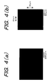
  • Fig. 4(a) and Fig. 4(b) are micrographs of the micro-channel that has been experimentally fabricated by the inventors of this application.
  • Fig. 4(a) shows a result in which observation was made from the side surface of the sample, that is, from arrow A in Fig. 2, and
  • Fig. 4(b) shows a result in which the sample was mechanically cut off along B-B line in Fig. 2 from the top surface to the bottom surface and observation was made to a cross-section of a micro-channel, which is formed on the inside of the sample, in the direction perpendicular to the scanning direction of the beam of femtosecond laser light from arrow C.
  • Fig. 5(a) and Fig. 5(b) are exemplary views showing other constitution examples of the slit member.
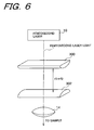
  • Fig. 6 is an exemplary view showing a constitution example of beam shape shaping means that is different from the slit member.
  • Fig. 2 shows the conceptual constitution exemplary view of the processing device for the inside of a transparent material according to the present invention.
  • a sample 100 which is made of photosensitive glass as the transparent material
  • the processing device of the inside of the transparent material according to the present invention is used, a case is shown for performing modification of a region that becomes a micro-channel 102 in order to form the micro-channel 102 inside the sample 100.
  • Forturan glass can be used as the photosensitive glass, for example.
  • the processing device for the inside of a transparent material shown in Fig. 2 is constituted by having a femtosecond laser 10 that irradiates femtosecond laser light having the pulse width of about 100 to 150 femtoseconds, for example, as the femtosecond laser light having the pulse width of a 10 -13 second order, a slit member 12 on which an approximately rectangular slit 12a is formed, through which the femtosecond laser light emitted from the femtosecond laser 10 passes, as the beam shape shaping means that shapes the beam shape of the cross-section in the direction perpendicular to the advance direction of laser light beam, which is emitted from the femtosecond laser 10, in a predetermined shape, and an objective lens 14 as a lens that focuses the femtosecond laser light, which has passed through the slit 12a of the slit member 12, on the inside of the sample 100.
  • the processing device for the inside of a transparent material is provided with a moving table 200 as moving means that relatively moves the light focus position of the femtosecond laser light, which is focused on the inside of the sample 100 by the objective lens 14, with respect to the sample 100, and the sample 100 is mounted on the moving table 200.
  • the moving table 200 is designed to be movable arbitrarily in X-direction, Y-direction and Z-direction in Fig. 2, and such movement is controlled by drive means (not shown) such as a motor.
  • the processing device for the inside of a transparent material is aligned and fixed with respect to the sample 100, but is constituted such that the light focus position of the femtosecond laser light, which is focused on the inside of the sample 100, is arbitrarily moved in X-direction, Y-direction and Z-direction with respect to the sample 100 by arbitrarily moving the sample 100 in X-direction, Y-direction and Z-direction after mounting the sample on the moving table 200, and the femtosecond laser light is enabled to scan arbitrarily in X-direction, Y-direction and Z-direction inside the sample 100.
  • the approximately rectangular slit 12a formed on the slit member 12 is formed so as to extend in X-direction where femtosecond laser light is allowed to scan relatively with respect to the sample 100, and its length L in a longitudinal direction is 3mm, for example, and length W in a width direction is 0.5mm, for example.
  • a lens having the numerical aperture of 0.46 (magnification: ⁇ 20), for example, can be used as the objective lens 14.
  • femtosecond laser light emitted from the femtosecond laser 10 passes through the slit 12a of the slit member 12, and is allowed to enter the objective lens 14 with a beam shape same as the shape of the slit 12a.
  • the beam shape of the cross-section in the direction perpendicular to the advance direction of the beam of femtosecond laser light, which is emitted from the femtosecond laser 10 is shaped in an approximately rectangular shape when the femtosecond laser light passes through the slit 12a of the slit member 12, and femtosecond laser light, whose beam shape of the cross-section in the direction perpendicular to the advance direction of the beam is shaped in an approximately rectangular shape, is allowed to enter the objective lens 14.
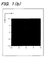
  • the spatial intensity distribution in the direction parallel to the advance direction of the beam of femtosecond laser light at the focal spot is improved significantly according to the calculation result of the inventors of this application, and the spatial intensity distribution of a substantially perfect circle is obtained at the central portion of the focal spot as shown in Fig. 1(b)
  • reference code P in Fig. 2 shows the shape of the focal spot of femtosecond laser light on X-Y plane in Fig. 2.
  • the reason why the spatial intensity distribution was improved by the processing device for the inside of a transparent material according to the present invention is because the beam shape of femtosecond laser light was shaped in a long beam shape with respect to X-direction by the slit 12a, the diffraction effect occurred in this direction, and the beam spread in Y-direction at the point where the beam was focused by the objective lens 14 (the beam shape of femtosecond laser light at the focal spot matches the beam shape of femtosecond laser light that entered the objective lens 14, to which Fourier transformation was performed).
  • the beam width in Y-direction increases when the beam shape of femtosecond laser light is shaped long with respect to X-direction
  • a region to be processed by femtosecond laser light can be limited narrower since the spatial intensity at the central area of the light focus position is considerably weaker comparing to the case where the beam was not shaped.
  • the width of a formed micro-channel is narrower when the beam was shaped despite that the beam width increased in Y-direction as shown in Figs. 3 and 4.
  • a direction where the slit (shown by reference numeral 12a' in Fig. 5(a)) is positioned is rotated by 90 degrees from the direction of the slit 12a shown in Fig. 2 to shape the beam in a long beam shape in Y-direction
  • a long beam shape in X-direction being a beam scanning direction is formed at the light focus position of femtosecond laser light, so that an even narrower channel can be fabricated.
  • the experiment is for forming the micro-channel 102 inside the sample 100 made of photosensitive glass by using the processing device for the inside of a transparent material.
  • femtosecond laser light is focused on the inside of the sample 100
  • the sample 100 mounted on the moving table 200 is moved in X-direction by moving the moving table 200 in X-direction, and a flow path 102a of the micro-channel 102 is modified by scanning the femtosecond laser light in X-direction relatively with respect to the sample 100.
  • the sample 100 mounted on the moving table is moved in Z-direction by moving the moving table 200 in Z-direction, and a flow path 102b of the micro-channel 102 is modified by scanning the femtosecond laser light in Z-direction relatively with respect to the sample 100. It is to be noted that the sample 100 is moved in Z-direction such that the focal spot of the femtosecond laser light is allowed to scan to the top surface 100a of the sample 100 in such occasion.
  • the sample 100 mounted on the moving table 200 is moved in Z-direction by moving the moving table 200 in Z-direction, and a flow path 102c of the micro-channel 102 is modified by scanning the femtosecond laser light in Z-direction relatively with respect to the sample 100. It is to be noted that the sample 100 is moved in Z-direction such that the focal spot of the femtosecond laser light is allowed to scan to the top surface 100a of the sample 100 in such occasion.
  • a region to which the femtosecond laser light was irradiated has etching rate on hydrofluoric acid solution several tens times to a region to which the femtosecond laser light was not irradiated. It is possible to selectively etch only the region to which the femtosecond laser light was irradiated by utilizing the difference of etching rate, and the micro-channel 102 was formed in a penetrated manner.
  • Figs. 3(a), (b), (c) and (d) show the micrographs of the micro-channel 102 that was formed in the sample 100 as described above. It is to be noted that Figs. 3(a) and (b) show the conventional case where the femtosecond laser light was directly focused by the objective lens 14 and irradiated on the inside of the sample 100 without using the slit member 12, and Figs. 3(c) and (d) show the case of the present invention where the femtosecond laser light was focused by the objective lens 14 and irradiated on the inside of the sample 100 after the light was allowed to pass through the approximately rectangular slit 12a by using the slit member 12.
  • Fig. 3(a) and (c) show the results in which observation was made from the side surface of the sample 100, that is, from arrow A in Fig. 2, and Fig. 3(b) and (d) show the results in which the sample 100 was mechanically cut off along B-B line in Fig. 2 from the top surface 100a to the bottom surface 100b and observation was made to the cross-section of the micro-channel 102, which was formed on the inside of the sample 100, in the direction perpendicular to the scanning direction of the beam of femtosecond laser light from arrow C.
  • the length of the cross-sectional shape of the micro-channel 102 in a horizontal direction (width direction) is 40 ⁇ m for the one shown in Fig. 3(b) and 38 ⁇ m for the one shown in Fig. 3 (d), where the length when the slit 12 was used is slightly narrower.
  • the length of the cross-sectional shape of the micro-channel 102 in a vertical direction is 119 ⁇ m for the one shown in Fig. 3(b) and 60 ⁇ m for the one shown in Fig. 3(d), where a large difference is between the both. Consequently, the aspect ratio that is the ratio of lengths in the vertical direction and the horizontal direction of the cross-sectional shape of the micro-channel 102 is "3" for the one shown in Fig. 3(b) and "1.6” for the one shown in Fig. 3(d), and thus the aspect ratio was improved significantly from “3" to "1.6” by allowing the femtosecond laser light to pass through the slit 12a.
  • Figs. 4(a) and (b) show the results of experiment that was conducted under the completely same conditions as the experiment shown in Fig. 3 except that the size of the approximately rectangular slit 12a formed on the slit member 12 was set to 3mm for the length L in the longitudinal direction and 0.2mm for the length W in the width direction.
  • Fig. 4(a) shows the result in which observation was made from the side surface of the sample 100, that is, from arrow A in Fig. 2
  • Fig. 4(b) shows the result in which the sample 100 was mechanically cut off along B-B line in Fig.
  • the aspect ratio is improved and the cross-sectional shape of the micro-channel 102 becomes a substantially perfect circle.
  • the beam shape shaping means that shapes the beam shape of a cross-section in a direction perpendicular to the advance direction of laser light beam, which is emitted from a femtosecond laser, in a predetermined shape
  • the slit member 12 was used, where the approximately rectangular slit 12a, through which the femtosecond laser light emitted from the femtosecond laser 10 passes, was formed along the X-direction in Fig. 2 out of the scanning directions of the femtosecond laser light.
  • the invention is not limited to this.
  • a slit member 12' (refer to Fig. 5(a)) may be used, where an approximately rectangular slit 12a, through which the femtosecond laser light emitted from the femtosecond laser 10 passes, is formed along the Y-direction perpendicular to the X-direction in Fig. 2 out of the scanning directions of the femtosecond laser light.
  • a slit member 12 (refer to Fig. 5 (b)) on which a cross-shaped slit 12a" is formed may be used.
  • an appropriate shape can be selected as the shape of the slit through which the femtosecond laser light emitted from the femtosecond laser 10 passes, and the arrangement position when arranging the slit with respect to the femtosecond laser light emitted from the femtosecond laser 10 can be appropriately selected.
  • a narrower micro-channel can be formed as described above.
  • the invention can be also applied not only for the fabrication of the micro-channel and the optical waveguide but also the micro-void, the three-dimensional memory, and the photonic crystal.
  • the beam shape shaping means that shapes the beam shape of a cross-section in a direction perpendicular to the advance direction of laser light beam, which is emitted from a femtosecond laser, in a predetermined shape
  • the slit member 12 was used, where the approximately rectangular slit 12a, through which the femtosecond laser light emitted from the femtosecond laser 10 passes, was formed along the scanning direction of the femtosecond laser light.
  • the invention is not limited to this.
  • the first cylindrical lens 300 having the focal distance of f1 and the second cylindrical lens 302 having the focal distance of f2 should be sequentially arranged between the femtosecond laser 10 and the objective lens 14 such that the lenses become perpendicular to the advance direction of the beam of femtosecond laser light emitted from the femtosecond laser 10 and extend parallelly with each other and in a same direction.
  • the distance between the first cylindrical lens 300 and the second cylindrical lens 302 shall be "f1+f2".
  • the beam shape of a cross-section in a direction perpendicular to the advance direction of laser light beam which was emitted from the femtosecond laser 10 and sequentially made incident to the first cylindrical lens 300 and the second cylindrical lens 302, becomes an approximately rectangular shape when it is emitted from the second cylindrical lens, and the femtosecond laser light, where the beam shape of a cross-section in a direction perpendicular to the advance direction of the beam is shaped in the approximately rectangular shape, enters the objective lens 14 and focused.
  • the moving table 200 moved the sample 100 to relatively move the focal spot of femtosecond laser light with respect to the sample 100.
  • the invention is not limited to this.
  • the processing device for the inside of a transparent material is constituted to move with respect to the sample 100, and the constitution may be in such a manner that the focal spot of femtosecond laser light on the inside of the sample 100 is allowed to scan by moving the processing device for the inside of a transparent material.
  • the present invention Since the present invention is constituted as described above, it exerts superior effect that a shape, whose cross-sectional shape in a direction parallel to the advance direction of the beam of femtosecond laser light, is a substantially perfect circle can be obtained as the processed shape such as a modified shape and a worked shape even if femtosecond laser light is focused on the inside of a transparent material by using a condenser lens having relatively small numerical aperture by which working distance of several mm or more can be secured.
Landscapes

  • Optics & Photonics (AREA)
  • Engineering & Computer Science (AREA)
  • Physics & Mathematics (AREA)
  • Chemical & Material Sciences (AREA)
  • Mechanical Engineering (AREA)
  • General Chemical & Material Sciences (AREA)
  • Plasma & Fusion (AREA)
  • Chemical Kinetics & Catalysis (AREA)
  • Oil, Petroleum & Natural Gas (AREA)
  • Life Sciences & Earth Sciences (AREA)
  • Geochemistry & Mineralogy (AREA)
  • Materials Engineering (AREA)
  • Organic Chemistry (AREA)
  • Health & Medical Sciences (AREA)
  • Toxicology (AREA)
  • Laser Beam Processing (AREA)
  • Optical Integrated Circuits (AREA)

Abstract

A shape with a substantially perfect circle is obtained as a processed shape such as a modified shape or a worked shape at a light focus point in a cross-section in a direction parallel to an advance direction of a femtosecond laser light beam. A section in a direction perpendicular to an advance direction of a laser light beam emitted from a femtosecond laser (10) is formed in a predetermined shaped. The laser light of which sectional shape in the direction perpendicular to the advance direction is formed in the predetermined shape is entered into a lens (14). The light is focused by the lens inside a transparent material (100) and processes the inside of the transparent material.

Description

Technical Field
The present invention relates to a method and a device for processing the inside of a transparent material, more specifically to a method and a device for processing the inside of a transparent material, which is preferably used in performing processing such as modification and working of the inside of the transparent material with respect to laser light of femtosecond laser light having the pulse width of a 10-13 second order.
Background Art
Conventionally, there has been known femtosecond laser light, which has the pulse width of a 10-13 second order as a laser light source of a sub-picosecond or less.
When femtosecond laser light being laser light that is emitted from such femtosecond laser, which is a femtosecond laser having the pulse width of about 100 to 150 femtoseconds ("laser light that is emitted from femtosecond laser" shall be referred to as "femtosecond laser light" in this specification), for example, is focused on the inside of a transparent material with respect to the femtosecond laser light (a transparent material with respect to predetermined femtosecond laser light shall be appropriately referred to simply as a "transparent material" in this specification) via a lens, there is known a phenomenon that multiphoton absorption occurs only at a focal spot being a light focus position and processing such as the modification or the working of the focal spot inside the transparent material can be performed.
In recent years, report has been made that refraction index is changed, crystal precipitation is performed, or a micro-void is generated inside a glass material that is transparent with respect to the femtosecond laser light, with the use of such phenomenon. Furthermore, report has been made regarding the fabrication of an optical waveguide, a three-dimensional memory, a photonic crystal, or a micro-channel.
Meanwhile, regarding the structure of the above-described micro-void or the like that has been fabricated using the above-described phenomenon, when observation was made for the cross-sectional shape in a direction parallel to the advance direction of the beam of femtosecond laser light, it was made clear that the cross-sectional shape greatly depended on the longitudinal direction of the femtosecond laser light at the focal spot of the femtosecond laser light, that is, the spatial intensity distribution in a direction parallel to the advance direction of the beam of femtosecond laser light.
Specifically, according to the calculation result of the inventors of this application, when the femtosecond laser light is focused using an objective lens having the numerical aperture (NA) of 0.46 ("numerical aperture = 0.46" is equivalent to magnification of ×20), the spatial intensity distribution in the direction parallel to the advance direction of the beam of femtosecond laser light at the focal spot (spatial intensity distribution on a Y-Z plane in Fig. 2) should be the intensity distribution of a lengthwise elliptical shape extending in the advance direction of the beam of femtosecond laser light, as shown in Fig. 1(a).
As a result, the processed shape such as a modified shape and a worked shape inside the transparent material became the lengthwise elliptical shape extending in the advance direction of the beam of femtosecond laser light by suffering from the spatial intensity distribution in the direction parallel to the advance direction of the beam of femtosecond laser light at the focal spot inside the transparent material.
However, there existed a problem that it was not desirable that the processed shape such as a modified shape and a worked shape inside the transparent material became the lengthwise elliptical shape extending in the advance direction of the beam of femtosecond laser light when industrial fabrication and usage of micro-channel or optical waveguide are taken in consideration. Specifically, as the processed shape such as a modified shape and a worked shape inside the transparent material, a shape whose cross-sectional shape in the direction parallel to the advance direction of the beam of femtosecond laser light is a substantially perfect circle was required.
Herein, in order to obtain a shape whose cross-sectional shape in the direction parallel to the advance direction of the beam of femtosecond laser light is a substantially perfect circle as the processed shape such as a modified shape and a worked shape inside the transparent material, the spatial intensity distribution in the direction parallel to the advance direction of the beam of femtosecond laser light should be a shape of a substantially perfect circle.
Generally, as a method of obtaining a shape whose cross-sectional shape in the direction parallel to the advance direction of the beam of femtosecond laser light is a substantially perfect circle as the processed shape such as a modified shape and a worked shape inside the transparent material while obtaining the spatial intensity distribution of a substantially perfect circle in the direction parallel to the advance direction of the beam of femtosecond laser light, the use of an objective lens having a large numerical aperture is considered.
Certainly, when the femtosecond laser light is focused on the inside of the transparent material using an objective lens having the numerical aperture of 1 or more and the processing such as the modification and working inside the transparent material is performed, there is known that a shape whose cross-sectional shape in the direction parallel to the advance direction of the beam of femtosecond laser light is the shape of substantially perfect circle is obtained as the processed shape such as a modified shape and a worked shape on the focal spot (Hiroaki MISAWA et al., Proc. SPIE Vol.4088, p29-32).
However, when the femtosecond laser light is focused on the inside of the transparent material using the objective lens having the numerical aperture of 1 or more, a working distance (the working distance is the distance between the objective lens and a sample that is the transparent material to be modified or worked) becomes several hundred µm or less (the working distance is 200 to 300µm when the femtosecond laser light is focused on the inside of the transparent material using an objective lens having the numerical aperture of 1), so that a problem was pointed out that the processing such as the modification and the working with respect to a region at a deep position inside the transparent material was impossible.
The present invention has been created in view of the above-described problems that prior art has, and it is an object of the present invention to provide a method and a device for processing the inside of a transparent material, which is capable of obtaining a cross-sectional shape in a direction parallel to the advance direction of the beam of femtosecond laser light is a substantially perfect circle as the processed shape such as a modified shape or a worked shape on a light focus position being a light focus position, even if the femtosecond laser light is focused on the inside of the transparent material using a condenser lens of a relatively small numerical aperture, by which the working distance of several mm or more can be secured.
Disclosure of the Invention
To achieve the above-described object, the present invention is a method in which a beam shape of a cross-section in a direction perpendicular to the advance direction of laser light beam, which has emitted from a femtosecond laser, is shaped in a predetermined shape, laser light whose beam shape of the cross-section in the direction perpendicular to the advance direction is shaped in the predetermined shape is allowed to enter a lens and the light is focused on the inside of a transparent material by the lens, and the inside of the transparent material is processed by the operation of the laser light that is focused on the inside of the transparent material.
Further, the present invention is a method in which the predetermined shape is an approximately rectangular shape.
Further, the present invention is a method in which the predetermined shape is an approximately cross shape.
Furthermore, the present invention is a device that has a femtosecond laser that emits laser light, beam shape shaping means that shapes the beam shape of a cross-section in the direction perpendicular to the advance direction of laser light beam, which is emitted from the femtosecond laser, in a predetermined shape, and a lens into which the laser light, whose beam shape of the cross-section in the direction perpendicular to the advance direction has been shaped in the predetermined shape by the beam shape shaping means, is allowed to enter and which focuses the laser light on the inside of the transparent material, in which the inside of the transparent material is processed by the operation of the laser light that has been focused on the inside of the transparent material by the lens.
In addition, the present invention is a device that further has moving means that relatively moves the light focus position of laser light, which is focused on the inside of the transparent material, with respect to the transparent material.
In addition, the present invention is a device in which the beam shape shaping means includes a slit of an approximately rectangular shape through which laser light emitted from the femtosecond laser light passes, and shapes the beam shape of the cross-section in the direction perpendicular to the advance direction of the laser light beam, which has been emitted from the femtosecond laser, in an approximately rectangular shape.
Further, the present invention is a device in which the beam shape shaping means includes a slit of an approximately cross shape through which laser light emitted from the femtosecond laser light passes, and shapes the beam shape of the cross-section in the direction perpendicular to the advance direction of the laser light beam, which has been emitted from the femtosecond laser, in an approximately cross shape.
Still further, the present invention is a device in which the beam shape shaping means is means where the first cylindrical lens and the second cylindrical lens are sequentially arranged in parallel, and shapes the beam shape of the cross-section in the direction perpendicular to the advance direction of the laser light beam, which has been emitted from the femtosecond laser, in an approximately rectangular shape.
Therefore, according to the above-described present invention, the spatial intensity distribution in the direction parallel to the advance direction of the beam of femtosecond laser light at the focal spot inside the transparent material is a substantially perfect circle, and consequently, a shape whose cross-sectional shape in the direction parallel to the advance direction of the beam of femtosecond laser light is a substantially perfect circle can be obtained.
Specifically, when the beam shape of the cross-section in the direction perpendicular to the advance direction of the laser light beam emitted from the femtosecond laser is shaped in the predetermined shape, which is an approximately rectangular shape or an approximately cross shape, for example, and entered into the lens, the spatial intensity distribution in the direction parallel to the advance direction of the beam of femtosecond laser light at the focal spot inside the transparent material becomes a substantially perfect circle due to diffraction effect. Accordingly, a shape whose cross-sectional shape in the direction parallel to the advance direction of the beam of femtosecond laser light is a substantially perfect circle can be obtained as the processed shape such as a modified shape and a worked shape on the inside of the transparent material.
Brief Description of the Drawings
  • Fig. 1(a) is a photograph showing a simulation view that shows a calculation result of the spatial intensity distribution in the direction parallel to the advance direction of the beam of femtosecond laser light on the focal spot when the femtosecond laser light is focused by using an objective lens having the numerical aperture of 0.46.
  • Fig. 1(b) is a photograph showing a simulation view that shows a calculation result of the spatial intensity distribution in the direction parallel to the advance direction of the beam of femtosecond laser light on the focal spot when femtosecond laser light is focused by using the processing device for the inside of a transparent material according to the present invention (the objective lens having the numerical aperture of 0.46 is used as an objective lens. In addition, the shape of a beam entered into the objective lens is "0.5mm×3mm".).
  • It is to be noted that the intensity becomes higher toward the center of the simulation view of Fig. 1(a) and Fig. 1(b).
    Fig. 2 is a conceptual constitution exemplary view of a processing device for the inside of a transparent material.
    Fig. 3(a), Fig. 3(b), Fig. 3(c), and Fig. 3(d) are micrographs of a micro-channel that has been experimentally fabricated by the inventors of this application. It is to be noted that Fig. 3(a) and Fig. 3(b) show a conventional case where the femtosecond laser light was directly focused by the objective lens and irradiated on the inside of a sample without using a slit member, and Fig. 3(c) and Fig. 3(d) show a case of the present invention where the femtosecond laser light was focused by the objective lens and irradiated on the inside of the sample after the light was allowed to pass through an approximately rectangular slit by using the slit member.
    Further, Fig. 3(a) and Fig. 3(c) show results in which observation was made from the side surface of the sample, that is, from arrow A in Fig. 2, and Fig. 3(b) and Fig. 3(d) shows results in which the sample was mechanically cut off along B-B line in Fig. 2 from the top surface to the bottom surface and observation was made to a cross-section of a micro-channel, which is formed on the inside of the sample, in the direction perpendicular to the scanning direction of the beam of femtosecond laser light from arrow C.
    Fig. 4(a) and Fig. 4(b) are micrographs of the micro-channel that has been experimentally fabricated by the inventors of this application. Fig. 4(a) shows a result in which observation was made from the side surface of the sample, that is, from arrow A in Fig. 2, and Fig. 4(b) shows a result in which the sample was mechanically cut off along B-B line in Fig. 2 from the top surface to the bottom surface and observation was made to a cross-section of a micro-channel, which is formed on the inside of the sample, in the direction perpendicular to the scanning direction of the beam of femtosecond laser light from arrow C.
    Fig. 5(a) and Fig. 5(b) are exemplary views showing other constitution examples of the slit member.
    Fig. 6 is an exemplary view showing a constitution example of beam shape shaping means that is different from the slit member.
    Explanation of Reference Numerals
    10
    Femtosecond laser
    12, 12', 12"
    Slit member
    12a, 12a', 12a"
    Slit
    14
    Objective lens
    100
    Sample
    100a
    Top surface
    100b
    Bottom surface
    102
    Micro-channel
    102a, 102b, 102c
    Flow path
    200
    Moving table
    300
    First cylindrical lens
    302
    Second cylindrical lens
    P
    Shape of focal spot of femtosecond laser light on X-Y plane in Fig. 2
    Best Mode for Carrying Out the Invention
    In the following, description will be made for one example of the embodiment of the method and the device for processing the inside of a transparent material according to the present invention based on the accompanying drawings.
    Fig. 2 shows the conceptual constitution exemplary view of the processing device for the inside of a transparent material according to the present invention. In Fig. 2, as processing inside a sample 100, which is made of photosensitive glass as the transparent material, while the processing device of the inside of the transparent material according to the present invention is used, a case is shown for performing modification of a region that becomes a micro-channel 102 in order to form the micro-channel 102 inside the sample 100. It is to be noted that Forturan glass can be used as the photosensitive glass, for example.
    The processing device for the inside of a transparent material shown in Fig. 2 is constituted by having a femtosecond laser 10 that irradiates femtosecond laser light having the pulse width of about 100 to 150 femtoseconds, for example, as the femtosecond laser light having the pulse width of a 10-13 second order, a slit member 12 on which an approximately rectangular slit 12a is formed, through which the femtosecond laser light emitted from the femtosecond laser 10 passes, as the beam shape shaping means that shapes the beam shape of the cross-section in the direction perpendicular to the advance direction of laser light beam, which is emitted from the femtosecond laser 10, in a predetermined shape, and an objective lens 14 as a lens that focuses the femtosecond laser light, which has passed through the slit 12a of the slit member 12, on the inside of the sample 100.
    Further, the processing device for the inside of a transparent material is provided with a moving table 200 as moving means that relatively moves the light focus position of the femtosecond laser light, which is focused on the inside of the sample 100 by the objective lens 14, with respect to the sample 100, and the sample 100 is mounted on the moving table 200. It is to be noted that the moving table 200 is designed to be movable arbitrarily in X-direction, Y-direction and Z-direction in Fig. 2, and such movement is controlled by drive means (not shown) such as a motor.
    Specifically, the processing device for the inside of a transparent material is aligned and fixed with respect to the sample 100, but is constituted such that the light focus position of the femtosecond laser light, which is focused on the inside of the sample 100, is arbitrarily moved in X-direction, Y-direction and Z-direction with respect to the sample 100 by arbitrarily moving the sample 100 in X-direction, Y-direction and Z-direction after mounting the sample on the moving table 200, and the femtosecond laser light is enabled to scan arbitrarily in X-direction, Y-direction and Z-direction inside the sample 100.
    Herein, the approximately rectangular slit 12a formed on the slit member 12 is formed so as to extend in X-direction where femtosecond laser light is allowed to scan relatively with respect to the sample 100, and its length L in a longitudinal direction is 3mm, for example, and length W in a width direction is 0.5mm, for example.
    Further, in the processing device for the inside of a transparent material, a lens having the numerical aperture of 0.46 (magnification: ×20), for example, can be used as the objective lens 14.
    In the above-described construction, femtosecond laser light emitted from the femtosecond laser 10 passes through the slit 12a of the slit member 12, and is allowed to enter the objective lens 14 with a beam shape same as the shape of the slit 12a. Specifically, the beam shape of the cross-section in the direction perpendicular to the advance direction of the beam of femtosecond laser light, which is emitted from the femtosecond laser 10, is shaped in an approximately rectangular shape when the femtosecond laser light passes through the slit 12a of the slit member 12, and femtosecond laser light, whose beam shape of the cross-section in the direction perpendicular to the advance direction of the beam is shaped in an approximately rectangular shape, is allowed to enter the objective lens 14.
    Then, the femtosecond laser light that has entered into the objective lens 14, which is femtosecond laser light whose beam shape of the cross-section in the direction perpendicular to the advance direction of the beam is shaped in an approximately rectangular shape same as the shape of the slit 12a, is focused by the objective lens 14, and focused on the focal spot being the light focus position located inside the sample 100.
    As described above, by focusing the femtosecond laser light by the objective lens 14 after allowing it pass through the slit 12a, the spatial intensity distribution in the direction parallel to the advance direction of the beam of femtosecond laser light at the focal spot (the spatial intensity distribution on Y-Z plane in Fig. 2) is improved significantly according to the calculation result of the inventors of this application, and the spatial intensity distribution of a substantially perfect circle is obtained at the central portion of the focal spot as shown in Fig. 1(b)
    It is to be noted that reference code P in Fig. 2 shows the shape of the focal spot of femtosecond laser light on X-Y plane in Fig. 2.
    Herein, the reason why the spatial intensity distribution was improved by the processing device for the inside of a transparent material according to the present invention is because the beam shape of femtosecond laser light was shaped in a long beam shape with respect to X-direction by the slit 12a, the diffraction effect occurred in this direction, and the beam spread in Y-direction at the point where the beam was focused by the objective lens 14 (the beam shape of femtosecond laser light at the focal spot matches the beam shape of femtosecond laser light that entered the objective lens 14, to which Fourier transformation was performed).
    Therefore, although the beam width in Y-direction increases when the beam shape of femtosecond laser light is shaped long with respect to X-direction, a region to be processed by femtosecond laser light can be limited narrower since the spatial intensity at the central area of the light focus position is considerably weaker comparing to the case where the beam was not shaped.
    Accordingly, the width of a formed micro-channel is narrower when the beam was shaped despite that the beam width increased in Y-direction as shown in Figs. 3 and 4.
    Further, as shown in Fig. 5(a), when a direction where the slit (shown by reference numeral 12a' in Fig. 5(a)) is positioned is rotated by 90 degrees from the direction of the slit 12a shown in Fig. 2 to shape the beam in a long beam shape in Y-direction, a long beam shape in X-direction being a beam scanning direction is formed at the light focus position of femtosecond laser light, so that an even narrower channel can be fabricated.
    Next, description will be made for the experiment results by the inventors of this application, which was conducted using the processing device for the inside of a transparent material.
    It is to be noted that, in the processing device for the inside of a transparent material used in the experiment, the size of the approximately rectangular slit 12a that was formed on the slit member 12 was set to 3mm as the length L in the longitudinal direction (refer to Fig. 2) and 0.5mm as the length W in the width direction (refer to Fig. 2). Further, the lens having the numerical aperture of 0.46 (magnification: ×20) was used as the objective lens 14. Moreover, light of "energy=490nJ" was used as the femtosecond laser light to be emitted from the femtosecond laser 10. Then, speed of the femtosecond laser light focused on the inside of the sample 100 when it is allowed to scan the inside of the sample 100 was set to "speed=250µm".
    The experiment is for forming the micro-channel 102 inside the sample 100 made of photosensitive glass by using the processing device for the inside of a transparent material. Firstly, femtosecond laser light is focused on the inside of the sample 100, the sample 100 mounted on the moving table 200 is moved in X-direction by moving the moving table 200 in X-direction, and a flow path 102a of the micro-channel 102 is modified by scanning the femtosecond laser light in X-direction relatively with respect to the sample 100.
    Subsequently, after the focal spot of the femtosecond laser light is positioned at one end portion of the flow path 102a, which has been modified by scanning the femtosecond laser light in X-direction, the sample 100 mounted on the moving table is moved in Z-direction by moving the moving table 200 in Z-direction, and a flow path 102b of the micro-channel 102 is modified by scanning the femtosecond laser light in Z-direction relatively with respect to the sample 100. It is to be noted that the sample 100 is moved in Z-direction such that the focal spot of the femtosecond laser light is allowed to scan to the top surface 100a of the sample 100 in such occasion.
    Similarly, after the focal spot of the femtosecond laser light is positioned at the other end portion of the flow path 102a, which has been modified by scanning the femtosecond laser light in X-direction, the sample 100 mounted on the moving table 200 is moved in Z-direction by moving the moving table 200 in Z-direction, and a flow path 102c of the micro-channel 102 is modified by scanning the femtosecond laser light in Z-direction relatively with respect to the sample 100. It is to be noted that the sample 100 is moved in Z-direction such that the focal spot of the femtosecond laser light is allowed to scan to the top surface 100a of the sample 100 in such occasion.
    When thermal processing is performed after the femtosecond laser light was irradiated on the sample 100 as described above, a region to which the femtosecond laser light was irradiated has etching rate on hydrofluoric acid solution several tens times to a region to which the femtosecond laser light was not irradiated. It is possible to selectively etch only the region to which the femtosecond laser light was irradiated by utilizing the difference of etching rate, and the micro-channel 102 was formed in a penetrated manner.
    Figs. 3(a), (b), (c) and (d) show the micrographs of the micro-channel 102 that was formed in the sample 100 as described above. It is to be noted that Figs. 3(a) and (b) show the conventional case where the femtosecond laser light was directly focused by the objective lens 14 and irradiated on the inside of the sample 100 without using the slit member 12, and Figs. 3(c) and (d) show the case of the present invention where the femtosecond laser light was focused by the objective lens 14 and irradiated on the inside of the sample 100 after the light was allowed to pass through the approximately rectangular slit 12a by using the slit member 12.
    Furthermore, Fig. 3(a) and (c) show the results in which observation was made from the side surface of the sample 100, that is, from arrow A in Fig. 2, and Fig. 3(b) and (d) show the results in which the sample 100 was mechanically cut off along B-B line in Fig. 2 from the top surface 100a to the bottom surface 100b and observation was made to the cross-section of the micro-channel 102, which was formed on the inside of the sample 100, in the direction perpendicular to the scanning direction of the beam of femtosecond laser light from arrow C.
    As shown in Figs. 3(a), (b), (c) and (d), the length of the cross-sectional shape of the micro-channel 102 in a horizontal direction (width direction) is 40µm for the one shown in Fig. 3(b) and 38µm for the one shown in Fig. 3 (d), where the length when the slit 12 was used is slightly narrower.
    Moreover, the length of the cross-sectional shape of the micro-channel 102 in a vertical direction (height direction) is 119µm for the one shown in Fig. 3(b) and 60µm for the one shown in Fig. 3(d), where a large difference is between the both. Consequently, the aspect ratio that is the ratio of lengths in the vertical direction and the horizontal direction of the cross-sectional shape of the micro-channel 102 is "3" for the one shown in Fig. 3(b) and "1.6" for the one shown in Fig. 3(d), and thus the aspect ratio was improved significantly from "3" to "1.6" by allowing the femtosecond laser light to pass through the slit 12a.
    Figs. 4(a) and (b) show the results of experiment that was conducted under the completely same conditions as the experiment shown in Fig. 3 except that the size of the approximately rectangular slit 12a formed on the slit member 12 was set to 3mm for the length L in the longitudinal direction and 0.2mm for the length W in the width direction. It is to be noted that Fig. 4(a) shows the result in which observation was made from the side surface of the sample 100, that is, from arrow A in Fig. 2, and Fig. 4(b) shows the result in which the sample 100 was mechanically cut off along B-B line in Fig. 2 from the top surface 100a to the bottom surface 100b and observation was made to the cross-section of the micro-channel 102, which is formed on the inside of the sample 100, in the direction perpendicular to the traveling direction of the beam of femtosecond laser light from arrow C.
    According to the experimental results shown in Figs. 4(a) and (b), by setting the length in the width direction of the approximately rectangular slit 12a to 0.2mm, the length in the horizontal direction of the cross-sectional shape of the micro-channel 102 became 25µm, the length in the vertical direction of the cross-sectional shape of the micro-channel 102 became 33µm, and the aspect ratio was further improved to "1.3".
    Therefore, when the length in the width direction W of the approximately rectangular slit 12a is made shorter, the aspect ratio is improved and the cross-sectional shape of the micro-channel 102 becomes a substantially perfect circle.
    It is to be noted that the above-described embodiments may be modified as shown in the following (1) to (5).
    (1) In the above-described embodiments, as the beam shape shaping means that shapes the beam shape of a cross-section in a direction perpendicular to the advance direction of laser light beam, which is emitted from a femtosecond laser, in a predetermined shape, the slit member 12 was used, where the approximately rectangular slit 12a, through which the femtosecond laser light emitted from the femtosecond laser 10 passes, was formed along the X-direction in Fig. 2 out of the scanning directions of the femtosecond laser light. However, it goes without saying that the invention is not limited to this.
    For example, a slit member 12' (refer to Fig. 5(a)) may be used, where an approximately rectangular slit 12a, through which the femtosecond laser light emitted from the femtosecond laser 10 passes, is formed along the Y-direction perpendicular to the X-direction in Fig. 2 out of the scanning directions of the femtosecond laser light.
    Alternatively, as the slit through which the femtosecond laser light emitted from the femtosecond laser 10 passes, a slit member 12 (refer to Fig. 5 (b)) on which a cross-shaped slit 12a" is formed may be used.
    Furthermore, an appropriate shape can be selected as the shape of the slit through which the femtosecond laser light emitted from the femtosecond laser 10 passes, and the arrangement position when arranging the slit with respect to the femtosecond laser light emitted from the femtosecond laser 10 can be appropriately selected.
    Herein, in the case of using the slit as shown in Fig. 5(a), a narrower micro-channel can be formed as described above.
    Further, in the case of using the slit as shown in Fig. 5(b), the intensity distribution of a perfect sphere (circular in all direction) instead of a perfect circle (circular only in one direction) is obtained. Therefore, by using the slit as shown in Fig. 5(b), the invention can be also applied not only for the fabrication of the micro-channel and the optical waveguide but also the micro-void, the three-dimensional memory, and the photonic crystal.
    (2) In the above-described embodiments, as the beam shape shaping means that shapes the beam shape of a cross-section in a direction perpendicular to the advance direction of laser light beam, which is emitted from a femtosecond laser, in a predetermined shape, the slit member 12 was used, where the approximately rectangular slit 12a, through which the femtosecond laser light emitted from the femtosecond laser 10 passes, was formed along the scanning direction of the femtosecond laser light. However, it goes without saying that the invention is not limited to this.
    Specifically, there is a fear that a large quantity of energy will be lost when shaping the beam shape of a cross-section in a direction perpendicular to the advance direction of laser light beam, which is emitted from a femtosecond laser 10, in a predetermined shape by using the slit member 12. To eliminate the fear of energy loss, the first cylindrical lens 300 having the focal distance of f1 and the second cylindrical lens 302 having the focal distance of f2 should be sequentially arranged between the femtosecond laser 10 and the objective lens 14 such that the lenses become perpendicular to the advance direction of the beam of femtosecond laser light emitted from the femtosecond laser 10 and extend parallelly with each other and in a same direction. In such occasion, the distance between the first cylindrical lens 300 and the second cylindrical lens 302 shall be "f1+f2".
    With the construction as above, the beam shape of a cross-section in a direction perpendicular to the advance direction of laser light beam, which was emitted from the femtosecond laser 10 and sequentially made incident to the first cylindrical lens 300 and the second cylindrical lens 302, becomes an approximately rectangular shape when it is emitted from the second cylindrical lens, and the femtosecond laser light, where the beam shape of a cross-section in a direction perpendicular to the advance direction of the beam is shaped in the approximately rectangular shape, enters the objective lens 14 and focused.
    Therefore, when the beam shape of a cross-section in a direction perpendicular to the advance direction of the beam of femtosecond laser light is shaped by using the two cylindrical lenses as described above, for example, loss is almost eliminated and a beam shape of the same approximately rectangular shape as the case where the slit member 12 on which the slit 12a was formed can be obtained.
    (3) In the above-described embodiments, the moving table 200 moved the sample 100 to relatively move the focal spot of femtosecond laser light with respect to the sample 100. However, it goes without saying that the invention is not limited to this.
    Specifically, on the contrary to the above-described embodiments, the processing device for the inside of a transparent material is constituted to move with respect to the sample 100, and the constitution may be in such a manner that the focal spot of femtosecond laser light on the inside of the sample 100 is allowed to scan by moving the processing device for the inside of a transparent material.
    (4) In the above-described embodiments, description was made for fabricating the micro-channel, but it goes without saying that the invention is not limited to this. The present invention can be applied for the fabrication of other structures such as the optical waveguide and the three-dimensional memory.
    (5) The above-described embodiments and the modifications shown in the above-described (1) to (4) may be used in combination appropriately.
    Industrial Applicability
    Since the present invention is constituted as described above, it exerts superior effect that a shape, whose cross-sectional shape in a direction parallel to the advance direction of the beam of femtosecond laser light, is a substantially perfect circle can be obtained as the processed shape such as a modified shape and a worked shape even if femtosecond laser light is focused on the inside of a transparent material by using a condenser lens having relatively small numerical aperture by which working distance of several mm or more can be secured.
    Claims (8)

    1. A method of processing the inside of a transparent material, comprising the steps of:
      shaping a beam shape of a cross-section in a direction perpendicular to the advance direction of laser light beam, which has been emitted from a femtosecond laser, in a predetermined shape;
      allowing the laser light, whose beam shape of the cross-section in the direction perpendicular to said advance direction is shaped in said predetermined shape, to enter a lens and focusing the light on the inside of a transparent material by the lens; and
      processing the inside of said transparent material by the operation of the laser light that has been focused on the inside of said transparent material.
    2. The method of processing the inside of a transparent material according to Claim 1, wherein
         said predetermined shape is an approximately rectangular shape.
    3. The method of processing the inside of a transparent material according to Claim 1, wherein
         said predetermined shape is an approximately cross shape.
    4. A device of processing the inside of a transparent material, comprising:
      a femtosecond laser that emits laser light;
      beam shape shaping means that shapes the beam shape of a cross-section in a direction perpendicular to the advance direction of laser light beam, which has been emitted from said femtosecond laser, in a predetermined shape; and
      a lens into which the laser light, whose beam shape of the cross-section in the direction perpendicular to said advance direction has been shaped in the predetermined shape by said beam shape shaping means, is allowed to enter and which focuses the laser light on the inside of a transparent material, wherein
      the inside of said transparent material is processed by the operation of the laser light that has been focused on the inside of said transparent material by said lens.
    5. The device of processing the inside of a transparent material according to Claim 4, said device further comprising:
      moving means that relatively moves the light focus position of laser light, which is focused on the inside of said transparent material, with respect to said transparent material.
    6. The device of processing the inside of a transparent material according to any one of Claims 4 and 5, wherein
         said beam shape shaping means includes a slit of an approximately rectangular shape through which laser light emitted from the femtosecond laser light passes, and shapes the beam shape of the cross-section in the direction perpendicular to the advance direction of the laser light beam, which has been emitted from said femtosecond laser, in an approximately rectangular shape.
    7. The device of processing the inside of a transparent material according to any one of Claims 4 and 5, wherein
         said beam shape shaping means includes a slit of an approximately cross shape through which laser light emitted from the femtosecond laser light passes, and shapes the beam shape of the cross-section in the direction perpendicular to the advance direction of the laser light beam, which has been emitted from said femtosecond laser, in an approximately cross shape.
    8. The device of processing the inside of a transparent material according to any one of Claims 4 and 5, wherein
         said beam shape shaping means is means where the first cylindrical lens and the second cylindrical lens are sequentially arranged in parallel, and shapes the beam shape of the cross-section in the direction perpendicular to the advance direction of the laser light beam, which has been emitted from said femtosecond laser, in an approximately rectangular shape.
    EP03755268A 2002-05-24 2003-05-15 METHOD AND DEVICE FOR PROCESSING THE INTERIOR OF A TRANSPARENT MATERIAL Withdrawn EP1535697A4 (en)

    Applications Claiming Priority (3)

    Application Number Priority Date Filing Date Title
    JP2002149931A JP3559827B2 (en) 2002-05-24 2002-05-24 Method and apparatus for processing inside transparent material
    JP2002149931 2002-05-24
    PCT/JP2003/006039 WO2003099507A1 (en) 2002-05-24 2003-05-15 Method and device for processing inside of transparent material

    Publications (2)

    Publication Number Publication Date
    EP1535697A1 true EP1535697A1 (en) 2005-06-01
    EP1535697A4 EP1535697A4 (en) 2007-06-13

    Family

    ID=29561221

    Family Applications (1)

    Application Number Title Priority Date Filing Date
    EP03755268A Withdrawn EP1535697A4 (en) 2002-05-24 2003-05-15 METHOD AND DEVICE FOR PROCESSING THE INTERIOR OF A TRANSPARENT MATERIAL

    Country Status (4)

    Country Link
    US (1) US7411151B2 (en)
    EP (1) EP1535697A4 (en)
    JP (1) JP3559827B2 (en)
    WO (1) WO2003099507A1 (en)

    Cited By (3)

    * Cited by examiner, † Cited by third party
    Publication number Priority date Publication date Assignee Title
    WO2007033445A1 (en) * 2005-09-22 2007-03-29 Trackinside, Société Anonyme Method for internal laser marking
    EP1964822A1 (en) * 2007-02-27 2008-09-03 Cristales Curvados S.A. Method for manufacturing decorated glass and glass thus obtained
    CN103949772A (en) * 2014-04-22 2014-07-30 上海大学 Method of preparing three-dimensional rotatable nano-grating in transparent material by femtosecond laser

    Families Citing this family (29)

    * Cited by examiner, † Cited by third party
    Publication number Priority date Publication date Assignee Title
    WO2005033033A1 (en) * 2003-10-06 2005-04-14 Hoya Corporation Glass component having through hole and production method therefor
    DE102004037949B4 (en) * 2004-08-05 2009-04-02 Forschungszentrum Karlsruhe Gmbh Process for the preparation of photonic crystals
    JP5002808B2 (en) * 2006-03-07 2012-08-15 国立大学法人北海道大学 Laser processing apparatus and laser processing method
    CA2622937A1 (en) * 2007-03-23 2008-09-23 Nec Corporation Marked body and manufacturing method thereof
    US20090045179A1 (en) * 2007-08-15 2009-02-19 Ellen Marie Kosik Williams Method and system for cutting solid materials using short pulsed laser
    WO2011089592A1 (en) * 2010-01-20 2011-07-28 Moshe Finarov A method of laser processing
    TWI426298B (en) * 2010-12-27 2014-02-11 Univ Nat Taiwan Science Tech Optical component and laser processing method
    JP5379172B2 (en) * 2011-01-11 2013-12-25 東山 亨 Femtosecond laser processing machine
    WO2012108316A1 (en) * 2011-02-08 2012-08-16 株式会社フジクラ Method for manufacturing substrate having micropore, and substrate
    JP5873488B2 (en) * 2011-05-25 2016-03-01 株式会社フジクラ Manufacturing method of substrate having micropores, and substrate having micropores
    EP2754524B1 (en) 2013-01-15 2015-11-25 Corning Laser Technologies GmbH Method of and apparatus for laser based processing of flat substrates being wafer or glass element using a laser beam line
    EP2781296B1 (en) 2013-03-21 2020-10-21 Corning Laser Technologies GmbH Device and method for cutting out contours from flat substrates using a laser
    JP6401248B2 (en) * 2013-05-15 2018-10-10 コーニンクレッカ フィリップス エヌ ヴェKoninklijke Philips N.V. LED having scattering mechanism in substrate
    FR3006068B1 (en) * 2013-05-24 2015-04-24 Saint Gobain PROCESS FOR OBTAINING A SUBSTRATE
    JP5744991B2 (en) * 2013-09-12 2015-07-08 東山 亨 Femtosecond laser processing machine
    US11556039B2 (en) 2013-12-17 2023-01-17 Corning Incorporated Electrochromic coated glass articles and methods for laser processing the same
    US10293436B2 (en) 2013-12-17 2019-05-21 Corning Incorporated Method for rapid laser drilling of holes in glass and products made therefrom
    WO2016001335A1 (en) 2014-07-01 2016-01-07 Qiova Micromachining method and system for patterning a material, and method for using one such micromachining system
    TWI730945B (en) 2014-07-08 2021-06-21 美商康寧公司 Methods and apparatuses for laser processing materials
    KR20170028943A (en) 2014-07-14 2017-03-14 코닝 인코포레이티드 System for and method of processing transparent materials using laser beam focal lines adjustable in length and diameter
    US11773004B2 (en) 2015-03-24 2023-10-03 Corning Incorporated Laser cutting and processing of display glass compositions
    LT6428B (en) * 2015-10-02 2017-07-25 Uab "Altechna R&D" Method and device for laser processing of transparent materials
    US10730783B2 (en) 2016-09-30 2020-08-04 Corning Incorporated Apparatuses and methods for laser processing transparent workpieces using non-axisymmetric beam spots
    US10067291B2 (en) 2016-10-13 2018-09-04 Stmicroelectronics Sa Method of manufacturing a waveguide
    KR102428350B1 (en) 2016-10-24 2022-08-02 코닝 인코포레이티드 Substrate processing station for laser-based machining of sheet-like glass substrates
    WO2021126662A1 (en) * 2019-12-20 2021-06-24 Avava, Inc. Systems and methods for formation of continuous channels within transparent materials
    CN111408856B (en) * 2020-04-15 2022-11-22 华东师范大学重庆研究院 Method and device for manufacturing micro-fluidic chip by femtosecond plasma grating
    CN111474622B (en) * 2020-04-16 2022-08-16 华东师范大学 Method for preparing three-dimensional optical waveguide and photonic device structure in transparent material
    CN112756819B (en) * 2020-12-24 2022-02-08 清华大学 System and method for processing micro-channel by femtosecond laser assisted by alternating electric field

    Family Cites Families (15)

    * Cited by examiner, † Cited by third party
    Publication number Priority date Publication date Assignee Title
    JPS5794482A (en) * 1980-12-05 1982-06-11 Hitachi Ltd Pattern forming device by laser
    JPS642790A (en) * 1986-11-14 1989-01-06 Mitsubishi Electric Corp Laser beam machine
    JPH02165881A (en) * 1988-12-15 1990-06-26 Nec Corp Shadow mask for laser marking device
    US5410125A (en) * 1990-10-11 1995-04-25 Harry Winston, S.A. Methods for producing indicia on diamonds
    FR2673557A1 (en) * 1991-03-08 1992-09-11 Ugine Aciers METHOD AND STATIC OPTICAL DEVICE FOR LASER IRRADIATION OF A MOLECULAR METAL PRODUCT AND ITS APPLICATION TO THE TREATMENT OF MAGNETIC TOLES.
    US5736709A (en) * 1996-08-12 1998-04-07 Armco Inc. Descaling metal with a laser having a very short pulse width and high average power
    JPH11269683A (en) 1998-03-18 1999-10-05 Armco Inc Method and apparatus for removing oxide from metal surface
    US6285002B1 (en) * 1999-05-10 2001-09-04 Bryan Kok Ann Ngoi Three dimensional micro machining with a modulated ultra-short laser pulse
    US6573026B1 (en) * 1999-07-29 2003-06-03 Corning Incorporated Femtosecond laser writing of glass, including borosilicate, sulfide, and lead glasses
    US6977137B2 (en) * 1999-07-29 2005-12-20 Corning Incorporated Direct writing of optical devices in silica-based glass using femtosecond pulse lasers
    JP3522671B2 (en) * 2000-01-27 2004-04-26 住友重機械工業株式会社 Marking method, apparatus, and marked optical member
    US6555783B2 (en) * 2000-02-03 2003-04-29 Canon Kabushiki Kaisha Laser processing method and laser processing apparatus
    JP3754857B2 (en) 2000-02-03 2006-03-15 キヤノン株式会社 Laser processing method
    TW503188B (en) * 2000-08-29 2002-09-21 Sumitomo Heavy Industries Marking method, device the optical member marked
    JP3736791B2 (en) * 2000-08-31 2006-01-18 シャープ株式会社 Laser processing method

    Cited By (5)

    * Cited by examiner, † Cited by third party
    Publication number Priority date Publication date Assignee Title
    WO2007033445A1 (en) * 2005-09-22 2007-03-29 Trackinside, Société Anonyme Method for internal laser marking
    BE1016782A3 (en) * 2005-09-22 2007-06-05 Laser Engineering Applic METHOD FOR INTERNAL LASER MARKING IN TRANSPARENT AND LASER MATERIALS AND DEVICE USED FOR THE APPLICATION OF SAID METHOD
    EP1964822A1 (en) * 2007-02-27 2008-09-03 Cristales Curvados S.A. Method for manufacturing decorated glass and glass thus obtained
    CN103949772A (en) * 2014-04-22 2014-07-30 上海大学 Method of preparing three-dimensional rotatable nano-grating in transparent material by femtosecond laser
    CN103949772B (en) * 2014-04-22 2016-01-13 上海大学 Fabrication of three-dimensional rotatable nanobody gratings in transparent materials by femtosecond laser

    Also Published As

    Publication number Publication date
    WO2003099507A1 (en) 2003-12-04
    US7411151B2 (en) 2008-08-12
    JP2003340579A (en) 2003-12-02
    EP1535697A4 (en) 2007-06-13
    JP3559827B2 (en) 2004-09-02
    US20060124618A1 (en) 2006-06-15

    Similar Documents

    Publication Publication Date Title
    EP1535697A1 (en) Method and device for processing inside of transparent material
    JP7562242B2 (en) Method for forming fine structures in the volume of a substrate made of brittle material - Patents.com
    KR102069214B1 (en) Laser machining method and chip
    KR100433896B1 (en) Laser marking method and apparatus, and marked member
    Sugioka et al. Three‐dimensional femtosecond laser micromachining of photosensitive glass for biomicrochips
    US8961806B2 (en) Laser processing method
    KR101369531B1 (en) Laser material processing system
    EP2054772B1 (en) Exposure apparatus
    EP1708008B1 (en) Beam homogenizer and laser irradition apparatus
    KR20120005432A (en) Laser processing device and laser processing method
    JP2007167875A (en) Laser internal scribing method
    KR101407993B1 (en) Method for cutting substrate
    JP2010142837A (en) Laser processing method
    JP2009056467A (en) Laser processing apparatus and laser processing method
    Cheng et al. 3D microstructuring inside Foturan glass by femtosecond laser
    US10675715B2 (en) Semiconductor element manufacturing method and manufacturing device
    WO2003099508A1 (en) Method and device for processing inside of transparent material
    WO2009115598A1 (en) Guiding device for guiding light beams, laser cutting device provided therewith and production device equipped therewith for producing a preform for fibre composite structures suitable for power flows
    JP2005077857A (en) Microscope having a plurality of focal points, laser processing apparatus including the microscope, and laser processing method using the apparatus
    KR20130112111A (en) Laser processing method
    JP2007319921A (en) Laser processing apparatus and laser processing method
    DE10004999A1 (en) Device for guiding light beam with rotation symmetrical beam profile, has transparent flat substrate that is flexible relative to surface normal with lateral input and output coupling regions
    JP2010221286A (en) Laser processing method
    JP5624174B2 (en) Workpiece processing method, workpiece dividing method, and laser processing apparatus
    DE102022100008A1 (en) Structured wafer and optoelectronic component produced therewith

    Legal Events

    Date Code Title Description
    PUAI Public reference made under article 153(3) epc to a published international application that has entered the european phase

    Free format text: ORIGINAL CODE: 0009012

    17P Request for examination filed

    Effective date: 20041130

    AK Designated contracting states

    Kind code of ref document: A1

    Designated state(s): AT BE BG CH CY CZ DE DK EE ES FI FR GB GR HU IE IT LI LU MC NL PT RO SE SI SK TR

    AX Request for extension of the european patent

    Extension state: AL LT LV MK

    DAX Request for extension of the european patent (deleted)
    RBV Designated contracting states (corrected)

    Designated state(s): DE FR GB

    A4 Supplementary search report drawn up and despatched

    Effective date: 20070516

    17Q First examination report despatched

    Effective date: 20071004

    STAA Information on the status of an ep patent application or granted ep patent

    Free format text: STATUS: THE APPLICATION IS DEEMED TO BE WITHDRAWN

    18D Application deemed to be withdrawn

    Effective date: 20131203