EP1535694A2 - Laser oscillator - Google Patents
Laser oscillator Download PDFInfo
- Publication number
- EP1535694A2 EP1535694A2 EP04027865A EP04027865A EP1535694A2 EP 1535694 A2 EP1535694 A2 EP 1535694A2 EP 04027865 A EP04027865 A EP 04027865A EP 04027865 A EP04027865 A EP 04027865A EP 1535694 A2 EP1535694 A2 EP 1535694A2
- Authority
- EP
- European Patent Office
- Prior art keywords
- laser
- optical output
- control
- feedback
- laser oscillator
- Prior art date
- Legal status (The legal status is an assumption and is not a legal conclusion. Google has not performed a legal analysis and makes no representation as to the accuracy of the status listed.)
- Granted
Links
Images


Classifications
-
- H—ELECTRICITY
- H01—ELECTRIC ELEMENTS
- H01S—DEVICES USING THE PROCESS OF LIGHT AMPLIFICATION BY STIMULATED EMISSION OF RADIATION [LASER] TO AMPLIFY OR GENERATE LIGHT; DEVICES USING STIMULATED EMISSION OF ELECTROMAGNETIC RADIATION IN WAVE RANGES OTHER THAN OPTICAL
- H01S3/00—Lasers, i.e. devices using stimulated emission of electromagnetic radiation in the infrared, visible or ultraviolet wave range
- H01S3/10—Controlling the intensity, frequency, phase, polarisation or direction of the emitted radiation, e.g. switching, gating, modulating or demodulating
- H01S3/13—Stabilisation of laser output parameters, e.g. frequency or amplitude
- H01S3/131—Stabilisation of laser output parameters, e.g. frequency or amplitude by controlling the active medium, e.g. by controlling the processes or apparatus for excitation
- H01S3/1312—Stabilisation of laser output parameters, e.g. frequency or amplitude by controlling the active medium, e.g. by controlling the processes or apparatus for excitation by controlling the optical pumping
-
- B—PERFORMING OPERATIONS; TRANSPORTING
- B23—MACHINE TOOLS; METAL-WORKING NOT OTHERWISE PROVIDED FOR
- B23K—SOLDERING OR UNSOLDERING; WELDING; CLADDING OR PLATING BY SOLDERING OR WELDING; CUTTING BY APPLYING HEAT LOCALLY, e.g. FLAME CUTTING; WORKING BY LASER BEAM
- B23K26/00—Working by laser beam, e.g. welding, cutting or boring
- B23K26/70—Auxiliary operations or equipment
- B23K26/702—Auxiliary equipment
-
- H—ELECTRICITY
- H01—ELECTRIC ELEMENTS
- H01S—DEVICES USING THE PROCESS OF LIGHT AMPLIFICATION BY STIMULATED EMISSION OF RADIATION [LASER] TO AMPLIFY OR GENERATE LIGHT; DEVICES USING STIMULATED EMISSION OF ELECTROMAGNETIC RADIATION IN WAVE RANGES OTHER THAN OPTICAL
- H01S3/00—Lasers, i.e. devices using stimulated emission of electromagnetic radiation in the infrared, visible or ultraviolet wave range
- H01S3/02—Constructional details
- H01S3/04—Arrangements for thermal management
-
- H—ELECTRICITY
- H01—ELECTRIC ELEMENTS
- H01S—DEVICES USING THE PROCESS OF LIGHT AMPLIFICATION BY STIMULATED EMISSION OF RADIATION [LASER] TO AMPLIFY OR GENERATE LIGHT; DEVICES USING STIMULATED EMISSION OF ELECTROMAGNETIC RADIATION IN WAVE RANGES OTHER THAN OPTICAL
- H01S3/00—Lasers, i.e. devices using stimulated emission of electromagnetic radiation in the infrared, visible or ultraviolet wave range
- H01S3/10—Controlling the intensity, frequency, phase, polarisation or direction of the emitted radiation, e.g. switching, gating, modulating or demodulating
- H01S3/13—Stabilisation of laser output parameters, e.g. frequency or amplitude
- H01S3/1305—Feedback control systems
-
- H—ELECTRICITY
- H01—ELECTRIC ELEMENTS
- H01S—DEVICES USING THE PROCESS OF LIGHT AMPLIFICATION BY STIMULATED EMISSION OF RADIATION [LASER] TO AMPLIFY OR GENERATE LIGHT; DEVICES USING STIMULATED EMISSION OF ELECTROMAGNETIC RADIATION IN WAVE RANGES OTHER THAN OPTICAL
- H01S3/00—Lasers, i.e. devices using stimulated emission of electromagnetic radiation in the infrared, visible or ultraviolet wave range
- H01S3/14—Lasers, i.e. devices using stimulated emission of electromagnetic radiation in the infrared, visible or ultraviolet wave range characterised by the material used as the active medium
- H01S3/16—Solid materials
- H01S3/163—Solid materials characterised by a crystal matrix
- H01S3/164—Solid materials characterised by a crystal matrix garnet
- H01S3/1643—YAG
Definitions
- the present invention relates to a laser oscillator and, more specifically, to a laser oscillator with a control device for enhancing the stability of the laser output.
- a laser oscillator has a stable laser output.
- a machining laser oscillator for example, the change of a machining state of a workpiece becomes larger as the laser output becomes unstable.
- cutting there may be a part of the workpiece which is not cut completely or has much dross.
- a welded part of the workpiece may have a wave shape. Therefore, many techniques regarding the stability of laser output have been developed.
- the stability of laser output of the laser oscillator is required especially when the laser oscillator is activated.
- the laser output cannot be properly controlled because the laser output varies very quickly. Therefore, as described in Japanese Patent Publication No. 2917642, a method is proposed in which the laser is previously oscillated, the temporal change of the output of the laser is detected by an optical sensor, and desired output can be obtained by a feedforward command regarding a current value.
- the feedforward command cannot deal with all operations and, therefore, a feedback command is necessary.
- Feedback control may be applied to a carbon dioxide laser, as described in Japanese Patent Publication (Kokoku) No. 6-96198. Also, it is known that the actual laser output can be detected and a microprocessor of a computer numerical control (CNC) device used to execute the feedback control based on the detected output.
- CNC computer numerical control
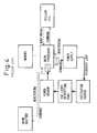
- the output of laser (YAG laser in this case) is detected by a power sensor provided as a monitor for the laser output.
- a signal detected by the power sensor is A/D converted and fed to a main processor.
- the main processor outputs a feedback command based on a program and a set value stored in a memory, in order to cancel a deviation between the actual laser output and a desired value (or a control set value).
- This feedback command is D/A converted and fed to a power supply.
- the power supply adjusts a current supplied to a laser excitation source corresponding to the feedback command, whereby the laser output is feedback controlled.
- the main processor outputs the command for such a feedback control, and simultaneously, executes a sequential control such as a control of a beam shutter, a control and condition monitoring of a chiller (or a coolant circulating device), condition monitoring of the power supply, and a detection of other alarms. Therefore, the main processor must process many controlled variables, which cause a problem that the main processor cannot command with a less than one milli-second period, or the feedback control with a less than one milli-second period cannot be possible.
- a method is proposed in which the main processor, executing a sequence control, outputs a command to an analog operational circuit and the laser output detected by a monitor is fed back to the analog operational circuit based on the command.
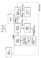
- An example of this, as a second prior art, is indicated in Fig. 5.
- the output of laser (YAG laser in this case) is detected by a power sensor provided as a monitor for the laser output.
- a signal in analog format detected by the power sensor is fed to an analog circuit for processing the signal.
- This analog circuit has a calculation function for comparing the actual laser output with a desired value (or a control set value) and calculating a deviation between them.
- the analog circuit sends a feedback signal to a power supply according to a command (or a D/A converted signal) fed by a main processor.
- the command fed by the main processor includes the desired value (or the control set value) of laser output and a gain value to be multiplied by the deviation.
- the main processor simultaneously executes a sequential control such as a control of a beam shutter, a control and condition monitoring of a chiller (or a coolant circulating device), condition monitoring of the power supply, and a detection of other alarms.
- a sequential control such as a control of a beam shutter, a control and condition monitoring of a chiller (or a coolant circulating device), condition monitoring of the power supply, and a detection of other alarms.
- the above feedback control using the analog circuit is not delayed due to controlled variables of the sequential control. Further, if the analog operational circuit realize a quick response, a high-speed control with a less than one milli-second period may be possible.
- the analog circuit has no flexibility and, therefore, using the analog circuit for controlling output of a device, such a laser oscillator, in which the condition varies every moment, may make maintenance of the device difficult.
- the present invention is intended to provide a laser oscillator for reducing the amount of controlled variables to be processed by the main processor, due to the sequential control and the feedback control of the laser output, in order to execute a high-speed feedback control.
- the present invention is also intended to improve maintenance of the laser device by executing a flexible control which the analog circuit cannot execute.
- a laser oscillator includes a power supply; an excitation source supplied with electric power by the power supply; a laser outputting part for outputting laser beam excited by the excitation source; an optical output detector for detecting the laser beam output by the laser outputting part and for outputting an optical output signal; an optical output commanding part for outputting an optical output command; and a feedback control part receiving the optical output command from the optical output commanding part and the optical output signal in digital format from the optical output detector, the feedback control generating a feedback signal for feedback controlling the laser output based on the comparison between the optical output command and the optical output signal in digital format, and outputting the feedback signal to the power supply.
- the period of the feedback control may be set to less than 200 ⁇ s.
- a photodiode may be used as the optical output detector.
- the photodiode preferably includes at least one material among Si, Ge, GaAs and InGaAs.
- the laser oscillator may include a plurality of power supplies.
- the feedback control part may feed the feedback signal to each of the power supplies individually.
- the laser oscillator may further include a coolant circulating device.
- the optical output commanding part may used for controlling and condition monitoring the coolant circulation device, for monitoring the condition of the power supply, and for detecting alarms.
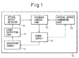
- a laser oscillator 10 includes a power supply 12; an excitation source 14 supplied with electric power by the power supply 12; a laser outputting part 16 for outputting laser beam excited by the excitation source 14; an optical output detector or a power sensor 18 for detecting the laser beam output by the laser outputting part 16 and for outputting an optical output signal; an optical output commanding part or a main processor 26 for outputting an optical output command; and a feedback control part or a sub processor 22 receiving the optical output command from the optical output commanding part 26 and the optical output signal in digital format from the optical output detector 18, the sub processor 22 generating a feedback signal for feedback controlling the laser output based on the comparison between the optical output command and the optical output signal in digital format, and outputting the feedback signal to the power supply 12.
- Fig. 2 is a block diagram indicating a fundamental constitution of the laser oscillator 10 according to a first embodiment of invention.
- the laser oscillator 10 includes one power supply 12; an excitation source 14 supplied with electric power by the power supply 12; a laser outputting part 16 for outputting a laser beam (a YAG laser in this case) excited by the excitation source 14; a power sensor 18 as an output monitor for detecting the YAG laser output; an A/D converter 20 for A/D converting a detected signal from the power sensor 18; a sub processor 22 receiving the A/D converted signal from the power sensor and outputting a feedback signal to the power supply 12; a D/A converter 24 for D/A converting the output signal or the feedback signal from the sub processor 22; and a main processor 26 for outputting an optical output command to the sub processor 22.
- the laser oscillator 10 may further include a memory 28 storing readable data for the sub processor 22 and the main processor 26; a chiller or a coolant circulating device 30 controlled and monitored by the main processor 26; and a beam shutter 32 for radiating, stopping and changing the progressing direction of the laser beam.
- the sub processor 22 executes some processes desired to be processed rapidly, among processes to be executed by the main processor of the above prior art (Fig. 4).
- One example of such a sub processor is a digital signal processor (DSP) which can execute a high-speed processing.
- DSP digital signal processor
- a high-speed processor executes processes more rapidly by reducing a number of commands to be processed.
- the sub processor 22 compares the current laser output value to a set value (a desired control value), and calculates a deviation value between them, in a predetermined period.
- the sub processor 22 generates a feedback signal for feedback controlling the laser output based on the deviation and outputs the feedback signal to the power supply 12 according to a command from the main processor 26.
- the feedback signal is D/A converted by the D/A converter 24 before reaching the power supply 12.
- the power supply 12 adjusts the current supplied to the laser excitation source 14, according to the feedback signal, in order to control the laser output.
- the command from the main processor 26 includes the set value (the desired control value) of the laser output.
- the data of the set value can be read from the memory 28 by the main processor 26.
- the main processor 26 is used for processing a sequential control such as monitoring the condition of the power supply 12, the control and monitoring of the chiller 30, and detection of other alarms. In other words, the main processor 26 is used to execute processes which do not need to be processed rapidly. Although the main processor 26 may control the beam shutter 32 which is desired to be high-speed controlled, it is preferable that the beam shutter 32 is controlled by the sub processor 22 instead.
- Fig. 3 shows one example, as a second embodiment, which includes points of the invention and such a system.
- a component of the second embodiment similar to a component of the first embodiment is indicated by a numeral added with 100 to a corresponding numeral of the first embodiment.
- the second embodiment three power supplies 112a, 112b and 112c for activating an excitation source 114 for the laser (YAG laser in this case) are provided. Accordingly, three D/A converter 124a, 124b and 124c for D/A converting signals fed to the power supplies are provided.
- Other components of the second embodiment may have same functions as corresponding components of the first embodiment.
- the excitation source 114 is activated by the power supplies, the laser beam is radiated and detected by a power sensor 118 arranged as a laser output monitor.
- a detected signal by the power sensor is A/D converted and fed to a sub processor 122.
- the sub processor 122 executes some processes which must be processed rapidly, among processes to be executed by a main processor 126.
- DSP digital signal processor
- the sub processor 122 compares the current laser output value to a set value (a desired control value) and, calculates a deviation value between them in a predetermined period.
- the sub processor 122 generates a feedback signal for feedback controlling the laser output based on the deviation and, outputs the feedback signals to the power supplies 112a, 112b and 112c individually, according to a command from the main processor 126.
- the feedback signals are D/A converted by the D/A converter 124a, 124b and 124c before reaching the power supplies 112a, 112b and 112c, respectively.
- the power supplies 112a, 112b and 112c adjust the current supplied to the laser excitation source 114 according to the feedback signals, in order to control the laser output.
- the command from the main processor 126 includes the set value (the desired control value) of the laser output.
- the data of the set value can be read from a memory 128 by the main processor 126.
- the main processor 126 is used for processing a sequential control such as condition monitoring of the power supplies 112a, 112b and 112c, a control and condition monitoring a chiller 130, and a detection of other alarms.
- the main processor 126 is used to execute processes which do not need to be processed rapidly.
- the main processor 126 may control a beam shutter 132 which is desired to be high-speed controlled, it is preferable that the beam shutter 132 is controlled by the sub processor 122 instead.
- the sub processor capable of executing a high-speed processing is used.
- Another important factor for speeding up the feedback control is the response of the power sensor for monitoring the laser output. Therefore, it is preferable that a photodiode is used as the power sensor.
- the typical photodiode includes one or more materials among Si, Ge, GaAs and InGaAs. These materials have short response times and normally respond within 200 ⁇ s. Therefore, the response of the feedback control may be less than 200 ⁇ s by combining the photodiode with the above DSP capable of high-speed processing.
- a thermopile detecting the output by temperature change is not used, because the response of the feedback control may be too long using the thermopile.
- the main processor executes the sequence control and the sub processor executes the feedback control of the laser output by the optical output command from the main processor. Therefore, the control load on the processor executing the feedback control is small and the feedback control may be executed rapidly.
- the period time of the feedback control may be several 10 ⁇ s order time and a start time of the feedback control may be one milli-second order time.
- a flexible control which an analog circuit cannot execute, may be executed by software. Further, as the function and the performance of the laser oscillator or the laser device may be easily improved by changing the software, maintenance of the laser device is highly improved.
- a plurality of power supplies is often used for a high output laser oscillator.
- the performance of the oscillator may further improved by commanding the power supplies individually by the sub processor.
Landscapes
- Physics & Mathematics (AREA)
- Engineering & Computer Science (AREA)
- Optics & Photonics (AREA)
- Plasma & Fusion (AREA)
- Electromagnetism (AREA)
- Mechanical Engineering (AREA)
- Lasers (AREA)
- Laser Beam Processing (AREA)
Abstract
Description
Claims (6)
- A laser oscillator comprising:a power supply (12);an excitation source (14) supplied with electric power by the power supply (12);a laser outputting part (16) for outputting laser beam excited by the excitation source (14);an optical output detector (18) for detecting the laser beam output by the laser outputting part (16) and for outputting an optical output signal;an optical output commanding part (26) for outputting an optical output command; anda feedback control part (22) receiving the optical output command from the optical output commanding part (26) and the optical output signal in digital format from the optical output detector (18), the feedback control part (22) generating a feedback signal for feedback controlling the laser output based on the comparison between the optical output command and the optical output signal in digital format, and outputting the feedback signal to the power supply (12).
- The laser oscillator as set forth in claim 1, wherein the period of the feedback control is less than 200 µs.
- The laser oscillator as set forth in claim 1, wherein a photodiode is used as the optical output detector (18).
- The laser oscillator as set forth in claim 3, wherein the photodiode (18) comprises at least one material among Si, Ge, GaAs and InGaAs.
- The laser oscillator as set forth in claim 1, wherein the laser oscillator comprises a plurality of power supplies (112a, 112b, 112c) and the feedback control part (22) feeds the feedback signal to each of the power supplies (112a, 112b, 112c) individually.
- The laser oscillator as set forth in claim 1, wherein the laser oscillator further comprises a coolant circulating device (30) and the optical output commanding part (26) is used for controlling and monitoring the coolant circulation device (30), for monitoring the power supply (12), and for detecting alarms.
Applications Claiming Priority (2)
| Application Number | Priority Date | Filing Date | Title |
|---|---|---|---|
| JP2003394956 | 2003-11-26 | ||
| JP2003394956A JP2005158984A (en) | 2003-11-26 | 2003-11-26 | Laser oscillator |
Publications (3)
| Publication Number | Publication Date |
|---|---|
| EP1535694A2 true EP1535694A2 (en) | 2005-06-01 |
| EP1535694A3 EP1535694A3 (en) | 2006-03-29 |
| EP1535694B1 EP1535694B1 (en) | 2007-04-18 |
Family
ID=34463792
Family Applications (1)
| Application Number | Title | Priority Date | Filing Date |
|---|---|---|---|
| EP04027865A Ceased EP1535694B1 (en) | 2003-11-26 | 2004-11-24 | Laser oscillator |
Country Status (4)
| Country | Link |
|---|---|
| US (1) | US20050111504A1 (en) |
| EP (1) | EP1535694B1 (en) |
| JP (1) | JP2005158984A (en) |
| DE (1) | DE602004005946T2 (en) |
Families Citing this family (12)
| Publication number | Priority date | Publication date | Assignee | Title |
|---|---|---|---|---|
| US6721508B1 (en) | 1998-12-14 | 2004-04-13 | Tellabs Operations Inc. | Optical line terminal arrangement, apparatus and methods |
| US8428461B2 (en) * | 2005-06-22 | 2013-04-23 | Tellabs Operations, Inc. | Apparatus for managing an optical signal |
| US7562826B2 (en) * | 2005-09-12 | 2009-07-21 | Symbol Technologies Inc | Scan engine with dual chip architecture for use in electro-optical readers |
| JP2008227418A (en) * | 2007-03-15 | 2008-09-25 | Nec Corp | Control device, control circuit, control method, and control program |
| JP5073796B2 (en) * | 2010-08-23 | 2012-11-14 | ファナック株式会社 | Laser oscillator controller |
| JP5068863B2 (en) * | 2011-02-17 | 2012-11-07 | ファナック株式会社 | High-power laser device that can accurately correct laser output |
| CN104105568B (en) * | 2013-02-14 | 2015-10-21 | 三菱电机株式会社 | Laser processing device, processing control device and pulse frequency control method |
| JP5845307B2 (en) * | 2014-04-11 | 2016-01-20 | ファナック株式会社 | Laser processing device that changes operation according to the length of power reduction time |
| CN109164760B (en) * | 2018-10-22 | 2020-07-14 | 大族激光科技产业集团股份有限公司 | A height-adjusting method and device with dual working modes |
| CN109346918B (en) * | 2018-12-26 | 2020-09-15 | 吉林大学 | A Portable Impedance Adaptive Laser Diode Driver Module |
| JP7343324B2 (en) * | 2019-07-26 | 2023-09-12 | ファナック株式会社 | Control device and control method for controlling a laser oscillator |
| KR102875674B1 (en) * | 2020-07-21 | 2025-10-23 | 삼성디스플레이 주식회사 | Laser apparatus and method for manufacturing display device |
Family Cites Families (10)
| Publication number | Priority date | Publication date | Assignee | Title |
|---|---|---|---|---|
| US4611270A (en) * | 1983-09-16 | 1986-09-09 | Questek Incorporated | Method and means of controlling the output of a pulsed laser |
| JP2917642B2 (en) * | 1992-01-24 | 1999-07-12 | 三菱電機株式会社 | Laser output control device |
| JP2830671B2 (en) * | 1993-01-07 | 1998-12-02 | 三菱電機株式会社 | Output control device of laser oscillator |
| JP3184359B2 (en) * | 1993-03-19 | 2001-07-09 | 富士通株式会社 | Semiconductor laser control method and semiconductor laser control device |
| JPH08195521A (en) * | 1995-01-17 | 1996-07-30 | Toshiba Corp | Laser oscillator |
| US5757831A (en) * | 1996-07-12 | 1998-05-26 | Lightwave Electronics Corp. | Electronic suppression of optical feedback instabilities in a solid-state laser |
| JP3007875B2 (en) * | 1998-04-20 | 2000-02-07 | オー・エム・シー株式会社 | Laser output detection method and device, and laser output control method and device using the method |
| JP2000294871A (en) * | 1999-04-09 | 2000-10-20 | Matsushita Electric Ind Co Ltd | Semiconductor laser control method and semiconductor laser control device |
| US6853655B2 (en) * | 2001-11-20 | 2005-02-08 | Spectra Physics, Inc. | System for improved power control |
| US6917632B2 (en) * | 2002-12-31 | 2005-07-12 | Intel Corporation | Interrupt driven wavelength locking |
-
2003
- 2003-11-26 JP JP2003394956A patent/JP2005158984A/en active Pending
-
2004
- 2004-11-23 US US10/994,613 patent/US20050111504A1/en not_active Abandoned
- 2004-11-24 EP EP04027865A patent/EP1535694B1/en not_active Ceased
- 2004-11-24 DE DE602004005946T patent/DE602004005946T2/en not_active Expired - Lifetime
Also Published As
| Publication number | Publication date |
|---|---|
| EP1535694A3 (en) | 2006-03-29 |
| DE602004005946T2 (en) | 2007-08-30 |
| US20050111504A1 (en) | 2005-05-26 |
| DE602004005946D1 (en) | 2007-05-31 |
| JP2005158984A (en) | 2005-06-16 |
| EP1535694B1 (en) | 2007-04-18 |
Similar Documents
| Publication | Publication Date | Title |
|---|---|---|
| EP1535694B1 (en) | Laser oscillator | |
| US6818856B2 (en) | Laser machining apparatus | |
| JP3315556B2 (en) | Laser processing equipment | |
| EP0557719B1 (en) | Apparatus for and method of controlling the output of a laser source | |
| US5182434A (en) | Laser beam machining method | |
| US5400351A (en) | Control of a pumping diode laser | |
| US5852276A (en) | Laser machining resuming method | |
| US20160026170A1 (en) | Numerical controller having suppressor that suppresses variation in velocity due to abrupt change in positional deviation | |
| JP3645216B2 (en) | Laser processing apparatus and control method thereof | |
| US7701990B2 (en) | Laser diode pumped solid-state laser oscillator and laser diode control method of the oscillator | |
| US20080025352A1 (en) | Laser apparatus having ability to automatically correct laser beam power | |
| US20060092999A1 (en) | Semiconductor-laser-pumped solid-state laser apparatus | |
| KR101425337B1 (en) | Laser processing apparatus, processing control apparatus, and pulse frequency control method | |
| JPH0146234B2 (en) | ||
| JP2706498B2 (en) | Laser processing equipment | |
| JPH02179373A (en) | Nc controller for laser beam machine | |
| JPH0255685A (en) | Nc laser device | |
| JP4241962B2 (en) | Laser processing method and apparatus | |
| JPH0362514B2 (en) | ||
| JP2755071B2 (en) | Quality control method of laser welding | |
| JPH0567831A (en) | Laser oscillation control device | |
| JP2024048835A (en) | Laser Processing Equipment | |
| JPS6167590A (en) | Laser beam machining equipment | |
| JPH08162704A (en) | Power control method of power supply for laser beam machine | |
| JP2005209759A (en) | Semiconductor laser heating device and laser processing machine |
Legal Events
| Date | Code | Title | Description |
|---|---|---|---|
| PUAI | Public reference made under article 153(3) epc to a published international application that has entered the european phase |
Free format text: ORIGINAL CODE: 0009012 |
|
| AK | Designated contracting states |
Kind code of ref document: A2 Designated state(s): AT BE BG CH CY CZ DE DK EE ES FI FR GB GR HU IE IS IT LI LU MC NL PL PT RO SE SI SK TR |
|
| AX | Request for extension of the european patent |
Extension state: AL HR LT LV MK YU |
|
| PUAL | Search report despatched |
Free format text: ORIGINAL CODE: 0009013 |
|
| AK | Designated contracting states |
Kind code of ref document: A3 Designated state(s): AT BE BG CH CY CZ DE DK EE ES FI FR GB GR HU IE IS IT LI LU MC NL PL PT RO SE SI SK TR |
|
| AX | Request for extension of the european patent |
Extension state: AL HR LT LV MK YU |
|
| 17P | Request for examination filed |
Effective date: 20060309 |
|
| GRAP | Despatch of communication of intention to grant a patent |
Free format text: ORIGINAL CODE: EPIDOSNIGR1 |
|
| AKX | Designation fees paid |
Designated state(s): DE |
|
| RIN1 | Information on inventor provided before grant (corrected) |
Inventor name: TAKAHASHI, HIROMITSU Inventor name: NISHIKAWA, YUJIROOM 14-408, FANUC MANSHONHARIMOMI Inventor name: MACHIDA, HISATADAFANUC DAI3VIRAKARAMATSU Inventor name: YOSHIDA,HIROYUKIROOM 11-207,FANUC MANSHONHARIMOMI Inventor name: ARITA, SOICHIROOM 10-305, FANUC MANSHONHARIMOMI |
|
| GRAS | Grant fee paid |
Free format text: ORIGINAL CODE: EPIDOSNIGR3 |
|
| GRAA | (expected) grant |
Free format text: ORIGINAL CODE: 0009210 |
|
| AK | Designated contracting states |
Kind code of ref document: B1 Designated state(s): DE |
|
| REF | Corresponds to: |
Ref document number: 602004005946 Country of ref document: DE Date of ref document: 20070531 Kind code of ref document: P |
|
| PLBE | No opposition filed within time limit |
Free format text: ORIGINAL CODE: 0009261 |
|
| STAA | Information on the status of an ep patent application or granted ep patent |
Free format text: STATUS: NO OPPOSITION FILED WITHIN TIME LIMIT |
|
| 26N | No opposition filed |
Effective date: 20080121 |
|
| REG | Reference to a national code |
Ref country code: DE Ref legal event code: R082 Ref document number: 602004005946 Country of ref document: DE Representative=s name: WUESTHOFF & WUESTHOFF PATENT- UND RECHTSANWAEL, DE |
|
| REG | Reference to a national code |
Ref country code: DE Ref legal event code: R082 Ref document number: 602004005946 Country of ref document: DE Representative=s name: WUESTHOFF & WUESTHOFF, PATENTANWAELTE PARTG MB, DE Effective date: 20111116 Ref country code: DE Ref legal event code: R081 Ref document number: 602004005946 Country of ref document: DE Owner name: FANUC CORPORATION, OSHINO-MURA, JP Free format text: FORMER OWNER: FANUC LTD., YAMANASHI, JP Effective date: 20111116 Ref country code: DE Ref legal event code: R082 Ref document number: 602004005946 Country of ref document: DE Representative=s name: WUESTHOFF & WUESTHOFF PATENT- UND RECHTSANWAEL, DE Effective date: 20111116 |
|
| REG | Reference to a national code |
Ref country code: DE Ref legal event code: R082 Ref document number: 602004005946 Country of ref document: DE Representative=s name: WUESTHOFF & WUESTHOFF, PATENTANWAELTE PARTG MB, DE Effective date: 20120202 Ref country code: DE Ref legal event code: R082 Ref document number: 602004005946 Country of ref document: DE Representative=s name: WUESTHOFF & WUESTHOFF PATENT- UND RECHTSANWAEL, DE Effective date: 20120202 Ref country code: DE Ref legal event code: R081 Ref document number: 602004005946 Country of ref document: DE Owner name: FANUC CORPORATION, OSHINO-MURA, JP Free format text: FORMER OWNER: FANUC CORP., YAMANASHI, JP Effective date: 20120202 |
|
| PGFP | Annual fee paid to national office [announced via postgrant information from national office to epo] |
Ref country code: DE Payment date: 20210929 Year of fee payment: 18 |
|
| REG | Reference to a national code |
Ref country code: DE Ref legal event code: R119 Ref document number: 602004005946 Country of ref document: DE |
|
| PG25 | Lapsed in a contracting state [announced via postgrant information from national office to epo] |
Ref country code: DE Free format text: LAPSE BECAUSE OF NON-PAYMENT OF DUE FEES Effective date: 20230601 |