EP1535656A1 - Befeuchter - Google Patents
Befeuchter Download PDFInfo
- Publication number
- EP1535656A1 EP1535656A1 EP04027932A EP04027932A EP1535656A1 EP 1535656 A1 EP1535656 A1 EP 1535656A1 EP 04027932 A EP04027932 A EP 04027932A EP 04027932 A EP04027932 A EP 04027932A EP 1535656 A1 EP1535656 A1 EP 1535656A1
- Authority
- EP
- European Patent Office
- Prior art keywords
- humidifier
- hollow fiber
- tubular member
- fiber membranes
- module
- Prior art date
- Legal status (The legal status is an assumption and is not a legal conclusion. Google has not performed a legal analysis and makes no representation as to the accuracy of the status listed.)
- Withdrawn
Links
- 239000012528 membrane Substances 0.000 claims abstract description 39
- 239000012510 hollow fiber Substances 0.000 claims description 28
- 239000000446 fuel Substances 0.000 abstract description 4
- 238000007599 discharging Methods 0.000 description 6
- 238000004519 manufacturing process Methods 0.000 description 5
- 230000006835 compression Effects 0.000 description 4
- 238000007906 compression Methods 0.000 description 4
- 230000003247 decreasing effect Effects 0.000 description 3
- 239000000463 material Substances 0.000 description 2
- XLYOFNOQVPJJNP-UHFFFAOYSA-N water Substances O XLYOFNOQVPJJNP-UHFFFAOYSA-N 0.000 description 2
- 230000008602 contraction Effects 0.000 description 1
- 238000005553 drilling Methods 0.000 description 1
- 230000000694 effects Effects 0.000 description 1
- 230000004048 modification Effects 0.000 description 1
- 238000012986 modification Methods 0.000 description 1
- 238000007789 sealing Methods 0.000 description 1
Images


Classifications
-
- H—ELECTRICITY
- H01—ELECTRIC ELEMENTS
- H01M—PROCESSES OR MEANS, e.g. BATTERIES, FOR THE DIRECT CONVERSION OF CHEMICAL ENERGY INTO ELECTRICAL ENERGY
- H01M8/00—Fuel cells; Manufacture thereof
- H01M8/04—Auxiliary arrangements, e.g. for control of pressure or for circulation of fluids
- H01M8/04082—Arrangements for control of reactant parameters, e.g. pressure or concentration
- H01M8/04089—Arrangements for control of reactant parameters, e.g. pressure or concentration of gaseous reactants
- H01M8/04119—Arrangements for control of reactant parameters, e.g. pressure or concentration of gaseous reactants with simultaneous supply or evacuation of electrolyte; Humidifying or dehumidifying
- H01M8/04126—Humidifying
- H01M8/04149—Humidifying by diffusion, e.g. making use of membranes
-
- B—PERFORMING OPERATIONS; TRANSPORTING
- B01—PHYSICAL OR CHEMICAL PROCESSES OR APPARATUS IN GENERAL
- B01D—SEPARATION
- B01D53/00—Separation of gases or vapours; Recovering vapours of volatile solvents from gases; Chemical or biological purification of waste gases, e.g. engine exhaust gases, smoke, fumes, flue gases, aerosols
- B01D53/22—Separation of gases or vapours; Recovering vapours of volatile solvents from gases; Chemical or biological purification of waste gases, e.g. engine exhaust gases, smoke, fumes, flue gases, aerosols by diffusion
-
- B—PERFORMING OPERATIONS; TRANSPORTING
- B01—PHYSICAL OR CHEMICAL PROCESSES OR APPARATUS IN GENERAL
- B01D—SEPARATION
- B01D63/00—Apparatus in general for separation processes using semi-permeable membranes
- B01D63/02—Hollow fibre modules
-
- B—PERFORMING OPERATIONS; TRANSPORTING
- B01—PHYSICAL OR CHEMICAL PROCESSES OR APPARATUS IN GENERAL
- B01D—SEPARATION
- B01D63/00—Apparatus in general for separation processes using semi-permeable membranes
- B01D63/02—Hollow fibre modules
- B01D63/04—Hollow fibre modules comprising multiple hollow fibre assemblies
- B01D63/046—Hollow fibre modules comprising multiple hollow fibre assemblies in separate housings
-
- H—ELECTRICITY
- H01—ELECTRIC ELEMENTS
- H01M—PROCESSES OR MEANS, e.g. BATTERIES, FOR THE DIRECT CONVERSION OF CHEMICAL ENERGY INTO ELECTRICAL ENERGY
- H01M8/00—Fuel cells; Manufacture thereof
- H01M8/04—Auxiliary arrangements, e.g. for control of pressure or for circulation of fluids
- H01M8/04082—Arrangements for control of reactant parameters, e.g. pressure or concentration
- H01M8/04089—Arrangements for control of reactant parameters, e.g. pressure or concentration of gaseous reactants
- H01M8/04119—Arrangements for control of reactant parameters, e.g. pressure or concentration of gaseous reactants with simultaneous supply or evacuation of electrolyte; Humidifying or dehumidifying
- H01M8/04126—Humidifying
-
- B—PERFORMING OPERATIONS; TRANSPORTING
- B01—PHYSICAL OR CHEMICAL PROCESSES OR APPARATUS IN GENERAL
- B01D—SEPARATION
- B01D2258/00—Sources of waste gases
- B01D2258/02—Other waste gases
- B01D2258/0208—Other waste gases from fuel cells
-
- B—PERFORMING OPERATIONS; TRANSPORTING
- B01—PHYSICAL OR CHEMICAL PROCESSES OR APPARATUS IN GENERAL
- B01D—SEPARATION
- B01D2313/00—Details relating to membrane modules or apparatus
- B01D2313/06—External membrane module supporting or fixing means
-
- Y—GENERAL TAGGING OF NEW TECHNOLOGICAL DEVELOPMENTS; GENERAL TAGGING OF CROSS-SECTIONAL TECHNOLOGIES SPANNING OVER SEVERAL SECTIONS OF THE IPC; TECHNICAL SUBJECTS COVERED BY FORMER USPC CROSS-REFERENCE ART COLLECTIONS [XRACs] AND DIGESTS
- Y02—TECHNOLOGIES OR APPLICATIONS FOR MITIGATION OR ADAPTATION AGAINST CLIMATE CHANGE
- Y02E—REDUCTION OF GREENHOUSE GAS [GHG] EMISSIONS, RELATED TO ENERGY GENERATION, TRANSMISSION OR DISTRIBUTION
- Y02E60/00—Enabling technologies; Technologies with a potential or indirect contribution to GHG emissions mitigation
- Y02E60/30—Hydrogen technology
- Y02E60/50—Fuel cells
-
- Y—GENERAL TAGGING OF NEW TECHNOLOGICAL DEVELOPMENTS; GENERAL TAGGING OF CROSS-SECTIONAL TECHNOLOGIES SPANNING OVER SEVERAL SECTIONS OF THE IPC; TECHNICAL SUBJECTS COVERED BY FORMER USPC CROSS-REFERENCE ART COLLECTIONS [XRACs] AND DIGESTS
- Y02—TECHNOLOGIES OR APPLICATIONS FOR MITIGATION OR ADAPTATION AGAINST CLIMATE CHANGE
- Y02P—CLIMATE CHANGE MITIGATION TECHNOLOGIES IN THE PRODUCTION OR PROCESSING OF GOODS
- Y02P70/00—Climate change mitigation technologies in the production process for final industrial or consumer products
- Y02P70/50—Manufacturing or production processes characterised by the final manufactured product
Definitions
- the present invention relates to a humidifier employing hollow fiber membranes and adapted for use in a fuel cell system.
- the disclosed humidifier arranges a bundle of hollow fiber membranes having a vapor permeation property in a cylindrical tube to form a hollow-fiber-membrane module.
- the cylinder is provided at a first end of a circumferential wall with a humidified gas outlet and at a second end of a circumferential wall with an inlet of dry gas (gas to be humidified).
- the module is provided at its axial ends with first and second header blocks, respectively, which are fastened together with through-bolts.
- the first header block has a wet gas introducing passage and a humidified gas discharging passage.
- the wet gas introducing passage is connected to the first end of tube, and communicating with each hollow fiber membrane.
- the humidified gas discharging passage is connected to the humidified gas outlet.
- the second header block has a wet gas discharging passage and a dry gas introducing passage.
- the humidified gas discharging passage is connected to the second end of tube, and communicating with each hollow fiber membrane.
- the dry gas introducing passage is connected to the dry gas inlet.
- a wet gas which is passed through the inside of the hollow fiber membranes, and is discharged from the second end of tube.
- a dry gas to be humidified which is passed along the outside of the hollow fiber membranes in the tube, and is discharged from the humidified gas outlet. Therealong, moisture is transmitted between the inside and outside of the hollow fiber membranes to humidify the dry gas to be humidified.
- the fastening force of the through-bolts always applies a compression force from the first and second header blocks to the tube.
- the tube needs to have a wall thickness to provide a sufficient support for the header blocks so that the humidifier has an increased weight and costs high in manufacturing.
- the hollow fiber membranes tend to axially contract as the temperature of the hollow fiber membranes increases. Accordingly, when the temperature of a gas passing through the hollow fiber membranes increases, the tube receives a compression stress due to the contraction of the hollow fiber membranes in addition to the initial compression stress exerted on the tube by the through-bolts. This sometimes results in deformation of the tube. When the tube contracts with increased temperature of a passing gas, gaps will be formed between the tube and the header blocks and sealing effects will deteriorate because of the gaps.
- a humidifier including a hollow-fiber-membrane module shaped tubular and a support configured to axially slideably support the module.
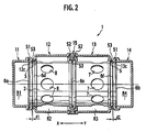
- a humidifier 1 in Figs. 1 to 3, has two hollow-fiber-membrane modules 2 and a housing 3 accommodating the modules 2.
- Each module 2 is configured as a moisture exchanger between a moist gas and a dry gas, and has a cylindrical tubular configuration.
- Each module 2 includes a cylinder 6 as tubular member.
- the cylinder 6 incorporates a bundle 5 of hollow fiber membranes 4 having a vapor permeation property.
- the cylinder 6 has a first-end opening 6a as the wet gas inlet, a second-end opening 6b as the wet gas outlet, a plurality of humidified gas outlets 8 on a first end side of the circumferential wall of cylinder 6, and a plurality of dry gas (gas to be humidified) inlets 7 on a second end side of the circumferential wall of cylinder 6.
- the hollow fiber membrane bundle 5 comprises about 5000 hollow fiber membranes 4.
- the bundle 5 is fixed inside the cylinder 6 with bonding materials 9a and 9b.
- the bonding materials 9a and 9b fill gaps between the membranes 4 so as to air-tightly close the end regions 6a and 6b of cylinder 6 with the ends of each membrane 4 being exposed and opened.
- the hollow fiber membranes 4 maintain a gaps therebetween.
- Each hollow fiber membrane 4 has an inner diameter of about 300 to 700 micrometers.
- the hollow fiber membrane 4 provides a gas passage through the inside thereof, condenses water contained in the gas, and transmits the condensed water to the outside via capillarity paths.
- the housing 3 has a separator 15, four cylindrical manifolds 11, 12, 13, and 14, each manifold having one bottom 11b, 12b, 13b,and 14b.
- the manifolds 11 and 12 are set together on a first side of the separator 15, and the manifolds 13 and 14 are set together on a second side of the separator 15 to define, in the housing 3, four chambers R1, R2, R3, and R4 aligned in an direction X-Y as shown by the arrow in Fig. 1 and 2.
- each module 2 extends through the two intermediate chambers R2 and R3 to the end chambers R1 and R4, to have open ends 6a and 6b in the end chambers R1 and R4, respectively.
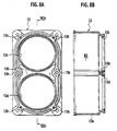
- the separator 15 has two through-holes 15b and 15c for receiving the modules 2, respectively, as shown in Fig. 7.
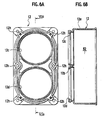
- the bottom 12b of manifold 12 has through-holes 12c and 12d for receiving the modules 2, respectively, as shown in Figs. 6.
- the bottom 13b of manifold 13 has through-holes 13c and 13d for receiving the modules 2, respectively, as shown in Figs. 8.
- the manifold 13 (the third manifold from the left side of Fig. 1) is provided at its circumferential wall with a dry gas (gas to be humidified) inlet 13e.
- the dry gas inlets 7 of module 2 are located in the chamber R3 in the manifold 13. Accordingly, the chamber R3 in the manifold 13 serves as a passage for introducing dry gas.
- the manifold 12 (the second manifold from the left side of Fig. 1) is provided at its circumferential wall with a humidified gas outlet 12e.
- the humidified gas outlets 8 of module 2 are located in the chamber R2 in the manifold 12. Accordingly, the chamber R2 in the manifold 12 serves as a passage for discharging humidified gas, which is humidified while flowing along the outside of the hollow fiber membranes 4 in the cylinder 6.
- the manifold 11 (the first manifold from the left side of Fig. 1) is provided at the bottom 11b with a wet gas inlet 11c.
- the first-end opening 6a (on the left side of Fig. 1) of the module 2 is located in the chamber R1 defined in the manifold 11. Accordingly, the chamber R1 in the manifold 11 serves as a passage for introducing wet gas.
- the manifold 14 (the fourth manifold from the left side of Fig. 1) is provided at the bottom 14b with a wet gas outlet 14c.
- the second-end opening 6b (on the right side of Fig. 1) of the module 2 is located in the chamber R4 in the manifold 14. Due to this, the chamber R4 in the manifold 14 serves as a passage for discharging wet gas.
- a reference F represents a filter.
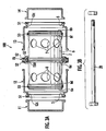
- the four manifolds 11 to 14 and separator 15 have through-holes 11h, 12h, 13h, 14h, and 15h in the peripheries thereof.
- the manifolds 11 to 14 and separator 15 are fastened together with through-bolts 20 (as show in Fig. 3B) passing through the through-holes 11h to 15h.
- a gasket S1 is provided between joint faces of manifold 11 and 12, a gasket S1 is provided, and between joint faces of manifold 13 and 14, another gasket S1 is provided.
- a gasket S2 is provided between joint faces of manifold 12 and separator 15, a gasket S2 is provided, and between joint faces of separator 15 and manifold 13, another gasket S2 is provided.
- the cylinder 6 has three flanges 6d, 6e, and 6f each formed with a groove for an O-ring S3. Each flange 6d, 6e, and 6f fits in the through-holes 12c and 12d, 13c and 13d, or 15b and 15c with the O-ring S3.
- Each through-holes 12c and 12d of manifold 12 has a step S serving as a stopper engaging with the flange 6d, to stop movements of module 2.
- Each through-hole 13c and 13d of manifold 13 has a step S serving as a stopper engaging with the flange 6f, to stop movements of module 2.
- This configuration prevents the modules 2 from falling off the casing 3.
- Between flange 6d and step (stopper) S there is a gap d1, and between the flange 6f and the step S, there is a gap d2, so that the module 2 is allowed to slide in the axial direction X-Y in the housing 3 within a sum "d1 + d2" of gaps d1 and d2.
- the module 2 in the housing 3 has a degree of freedom of movement in the axial direction X-Y.
- the above-noted humidifier 1 may be arranged in, for example, a fuel cell system (not shown), to exchange moisture between a cathode off-gas (wet gas) discharged from a cathode of a fuel cell and having a high moisture content and a dry cathode supply gas (gas to be humidified) pressurized by, for example, a supercharger and having a low moisture content.
- the humidifier 1 is used to humidify the dry cathode supply gas.
- the tubular module 2 is axially slideably supported in the support 3. In other wards, the tubular module 2 supported in the support 3 has freedom in an axial direction. This configuration applies no axial compression stress on the module 2. Therefore, the wall thickness of tubular module 2 can be decreased. This results in reducing the weight and manufacturing cost of the humidifier 1.
- the tubular module 2 includes the tubular member 6 and the bundle of hollow fiber membranes accommodated in the tubular member 6. Therefore, the wall thickness of the tubular member 6 can be decreased. This results in reducing the weight and manufacturing cost of the humidifier 1.
- the tubular member 6 includes the wet gas inlet 6a, wet gas outlet 6b, dry gas inlet 7, and humidified gas outlet 8, so that the module 2 exchanges moisture between a moist gas and a dry gas, with a simple structure.
- the support 3 defines the wet gas inlet passage R1, wet gas discharge passage R4, dry gas inlet passage R3, and humidified gas discharge passage R2, so that the support 3 distributes the moist gas and the dry gas to the modules 2, with a simple structure.
- the support 3 sets the four cylindrical manifolds 11 to 14 and the separator 15 one on another, to define the four chambers R1 to R4, to form the passages R1 to R4. This eliminates the conventional drilling work to drill passages of complicated shapes in head blocks, and therefore, can reduce the manufacturing cost of the humidifier 1.
- the tubular member 6 is provided at the first-end opening 6a with the wet gas inlet 6a, at a second-end opening 6b with the wet gas outlet 6b, at the circumferential wall of the tubular member 6 with the dry gas inlet 7 and the humidified gas outlet 8.
- the modules 2 extend through the two intermediate chambers R2 and R3, and the ends 6a and 6b of each of the modules 2 are exposed in the end chambers R1 and R4, respectively.
- the intermediate chamber R2 serves as a humidified gas discharge passage
- the intermediate chamber R3 as a dry gas inlet passage
- the end chamber R1 as a wet gas inlet passage
- the end chamber R4 as a wet gas discharge passage.
- Through-bolts 20 pass through all of the four manifolds 11 to 14 to fasten the four manifolds 11 to 14 together. Namely, it is not necessary for the embodiment to individually fasten the manifolds with bolts. This further reduces the manufacturing cost of the humidifier 1.
- the humidifier 1 employs a plurality of modules 2, to improve the humidifying capacity of the humidifier 1.
- the support 3 is configured as the housing 3 of the humidifier, to simplify the structure of humidifier.
- through-bolts 20 pass through not only the manifolds 11 to 14, but also the separator 15, which may be omitted. It is also possible to have the through-bolts 20 passing through only the two end manifolds 11 and 14.
- the prevent invention is applicable to a humidifier employing a single hollow-fiber-membrane module.
Landscapes
- Chemical & Material Sciences (AREA)
- Chemical Kinetics & Catalysis (AREA)
- General Chemical & Material Sciences (AREA)
- Engineering & Computer Science (AREA)
- Sustainable Energy (AREA)
- Sustainable Development (AREA)
- Manufacturing & Machinery (AREA)
- Electrochemistry (AREA)
- Life Sciences & Earth Sciences (AREA)
- Analytical Chemistry (AREA)
- Oil, Petroleum & Natural Gas (AREA)
- Fuel Cell (AREA)
- Air Humidification (AREA)
- Separation Using Semi-Permeable Membranes (AREA)
Applications Claiming Priority (2)
| Application Number | Priority Date | Filing Date | Title |
|---|---|---|---|
| JP2003397562 | 2003-11-27 | ||
| JP2003397562A JP2005156062A (ja) | 2003-11-27 | 2003-11-27 | 加湿器 |
Publications (1)
| Publication Number | Publication Date |
|---|---|
| EP1535656A1 true EP1535656A1 (de) | 2005-06-01 |
Family
ID=34463844
Family Applications (1)
| Application Number | Title | Priority Date | Filing Date |
|---|---|---|---|
| EP04027932A Withdrawn EP1535656A1 (de) | 2003-11-27 | 2004-11-24 | Befeuchter |
Country Status (3)
| Country | Link |
|---|---|
| US (1) | US7156375B2 (de) |
| EP (1) | EP1535656A1 (de) |
| JP (1) | JP2005156062A (de) |
Cited By (2)
| Publication number | Priority date | Publication date | Assignee | Title |
|---|---|---|---|---|
| CN104716365A (zh) * | 2013-12-11 | 2015-06-17 | 曼·胡默尔有限公司 | 尤其是用于燃料电池的增湿装置 |
| WO2015176900A1 (de) * | 2014-05-20 | 2015-11-26 | Mann+Hummel Gmbh | Filtermodul mit hohlfasern |
Families Citing this family (16)
| Publication number | Priority date | Publication date | Assignee | Title |
|---|---|---|---|---|
| US20070087232A1 (en) * | 2005-10-18 | 2007-04-19 | Robin Curtis M | Capacitor hybrid fuel cell power generator |
| US7477505B2 (en) * | 2005-10-18 | 2009-01-13 | General Hydrogen Corporation | Capacitor bank for electrical generator |
| US20070087239A1 (en) * | 2005-10-18 | 2007-04-19 | General Hydrogen Corporation | Fuel cell fluid management system |
| US20070087241A1 (en) * | 2005-10-18 | 2007-04-19 | General Hydrogen Corporation | Fuel cell power pack |
| KR100667433B1 (ko) * | 2005-11-02 | 2007-01-10 | 현대자동차주식회사 | 연료전지시스템용 가습장치 |
| US7938386B2 (en) * | 2006-03-13 | 2011-05-10 | GM Global Technology Operations LLC | Fuel cell air humidifier |
| JP4386099B2 (ja) * | 2007-06-07 | 2009-12-16 | トヨタ自動車株式会社 | 加湿器及び燃料電池システム |
| DE102007043330A1 (de) * | 2007-09-12 | 2009-03-19 | Carl Freudenberg Kg | Befeuchter |
| US9114225B1 (en) * | 2008-07-21 | 2015-08-25 | Corad Healthcare, Inc. | Membrane oxygen humidifier |
| KR101673667B1 (ko) * | 2014-07-31 | 2016-11-07 | 현대자동차주식회사 | 연료전지용 막 가습기의 중공사막 밀집도 분배 장치 |
| JP2021524133A (ja) * | 2018-06-04 | 2021-09-09 | コーロン インダストリーズ インク | 燃料電池膜加湿器 |
| JP7137988B2 (ja) * | 2018-07-24 | 2022-09-15 | 本田技研工業株式会社 | 加湿器 |
| DE102018213153A1 (de) * | 2018-08-07 | 2020-02-13 | Audi Ag | Befeuchter, Brennstoffzellenvorrichtung mit Befeuchter sowie Kraftfahrzeug |
| CN110173785B (zh) * | 2019-05-30 | 2021-10-26 | 广东美的制冷设备有限公司 | 用于空气调节设备的加湿滤芯和空气调节设备 |
| KR102546259B1 (ko) | 2020-05-22 | 2023-06-21 | 코오롱인더스트리 주식회사 | 가스켓 조립체 및 이를 포함하는 연료전지 가습기 |
| KR102577689B1 (ko) | 2020-05-22 | 2023-09-12 | 코오롱인더스트리 주식회사 | 가스켓 조립체 및 이를 포함하는 연료전지 가습기 |
Citations (5)
| Publication number | Priority date | Publication date | Assignee | Title |
|---|---|---|---|---|
| DE9300929U1 (de) * | 1993-01-23 | 1993-04-08 | Gkss-Forschungszentrum Geesthacht Gmbh, 21502 Geesthacht | Vorrichtung zum Filtern und Trennen von flüssigen und gasförmigen Medien und/oder zum Be- und Entgasen von Flüssigkeiten |
| JP2002066265A (ja) * | 2000-08-31 | 2002-03-05 | Honda Motor Co Ltd | 加湿装置 |
| JP2002066262A (ja) * | 2000-08-29 | 2002-03-05 | Honda Motor Co Ltd | 中空糸膜式加湿器 |
| US20020041989A1 (en) * | 2000-10-05 | 2002-04-11 | Honda Giken Kogyo Kabushiki Kaisha | Humidifying apparatus for fuel cell |
| JP2003065566A (ja) * | 2001-08-24 | 2003-03-05 | Honda Motor Co Ltd | ガス加湿器およびガス加湿システム |
Family Cites Families (10)
| Publication number | Priority date | Publication date | Assignee | Title |
|---|---|---|---|---|
| US835243A (en) * | 1905-09-22 | 1906-11-06 | Robert D Jeffreys | Oil-separator. |
| US2111936A (en) * | 1935-01-14 | 1938-03-22 | James A Murphy | Fluid purifier |
| DE123476C (de) * | 1960-09-19 | |||
| US4031012A (en) * | 1975-09-17 | 1977-06-21 | Gics Pharmaceuticals, Inc. | Separatory apparatus |
| US4707267A (en) * | 1987-01-22 | 1987-11-17 | The Dow Chemical Company | Device and method for separating individual fluids from a mixture of fluids |
| US5651810A (en) * | 1994-10-14 | 1997-07-29 | Monsanto Company | Apparatus and method for filtering and sampling airborne respiratory contaminants |
| JP3826627B2 (ja) * | 1999-07-16 | 2006-09-27 | 日産自動車株式会社 | ガス分離装置 |
| JP3927344B2 (ja) * | 2000-01-19 | 2007-06-06 | 本田技研工業株式会社 | 加湿装置 |
| DE10102358B4 (de) * | 2000-01-19 | 2007-09-13 | Honda Giken Kogyo K.K. | Befeuchter für eine Brennstoffzelle |
| JP3765531B2 (ja) * | 2001-03-30 | 2006-04-12 | 本田技研工業株式会社 | 加湿モジュール |
-
2003
- 2003-11-27 JP JP2003397562A patent/JP2005156062A/ja active Pending
-
2004
- 2004-11-24 EP EP04027932A patent/EP1535656A1/de not_active Withdrawn
- 2004-11-24 US US10/995,349 patent/US7156375B2/en not_active Expired - Fee Related
Patent Citations (5)
| Publication number | Priority date | Publication date | Assignee | Title |
|---|---|---|---|---|
| DE9300929U1 (de) * | 1993-01-23 | 1993-04-08 | Gkss-Forschungszentrum Geesthacht Gmbh, 21502 Geesthacht | Vorrichtung zum Filtern und Trennen von flüssigen und gasförmigen Medien und/oder zum Be- und Entgasen von Flüssigkeiten |
| JP2002066262A (ja) * | 2000-08-29 | 2002-03-05 | Honda Motor Co Ltd | 中空糸膜式加湿器 |
| JP2002066265A (ja) * | 2000-08-31 | 2002-03-05 | Honda Motor Co Ltd | 加湿装置 |
| US20020041989A1 (en) * | 2000-10-05 | 2002-04-11 | Honda Giken Kogyo Kabushiki Kaisha | Humidifying apparatus for fuel cell |
| JP2003065566A (ja) * | 2001-08-24 | 2003-03-05 | Honda Motor Co Ltd | ガス加湿器およびガス加湿システム |
Non-Patent Citations (2)
| Title |
|---|
| PATENT ABSTRACTS OF JAPAN vol. 2002, no. 07 3 July 2002 (2002-07-03) * |
| PATENT ABSTRACTS OF JAPAN vol. 2003, no. 07 3 July 2003 (2003-07-03) * |
Cited By (3)
| Publication number | Priority date | Publication date | Assignee | Title |
|---|---|---|---|---|
| CN104716365A (zh) * | 2013-12-11 | 2015-06-17 | 曼·胡默尔有限公司 | 尤其是用于燃料电池的增湿装置 |
| CN104716365B (zh) * | 2013-12-11 | 2019-03-05 | 曼·胡默尔有限公司 | 尤其是用于燃料电池的增湿装置 |
| WO2015176900A1 (de) * | 2014-05-20 | 2015-11-26 | Mann+Hummel Gmbh | Filtermodul mit hohlfasern |
Also Published As
| Publication number | Publication date |
|---|---|
| US20050116365A1 (en) | 2005-06-02 |
| US7156375B2 (en) | 2007-01-02 |
| JP2005156062A (ja) | 2005-06-16 |
Similar Documents
| Publication | Publication Date | Title |
|---|---|---|
| EP1535656A1 (de) | Befeuchter | |
| KR100834121B1 (ko) | 가습장치 | |
| EP2258464B1 (de) | Befeuchtungsmembranmodul | |
| US7314680B2 (en) | Integrated fuel cell power module | |
| CA2379429A1 (en) | Humidifying module | |
| US12611632B2 (en) | Humidifier | |
| CA2540176A1 (en) | External pressure type hollow fiber membrane module | |
| EP0873779A3 (de) | Modul mit selektiv durchlässigen Membranen | |
| US6805988B2 (en) | Humidifying apparatus for fuel cell | |
| US8181943B2 (en) | Humidifier | |
| JP2007283292A (ja) | 中空糸膜モジュール | |
| JP5211855B2 (ja) | 燃料電池の加湿装置 | |
| CN111683730A (zh) | 中空纤维膜组件 | |
| CN121307087A (zh) | 膜片堆叠和空气加湿器 | |
| EP4349465A1 (de) | Hohlfasermembranmodul und entfeuchtungs-/befeuchtungsvorrichtung | |
| US20090242474A1 (en) | Hollow fiber membrane module | |
| JP5151853B2 (ja) | 加湿装置 | |
| JP2003265933A (ja) | 中空糸膜モジュール及び加湿装置及び除湿装置 | |
| US20250023068A1 (en) | Hollow fiber membrane cartridge assembly | |
| JP2002219339A (ja) | 加湿モジュール | |
| JP2003157872A (ja) | 加湿装置 | |
| JP7724869B2 (ja) | 中空糸膜モジュール | |
| US20250364579A1 (en) | Membrane stack assembly for a humidifier of a fuel cell system | |
| CA3150084C (en) | Humidifier for fuel cells and cartridge therefor | |
| KR20260005749A (ko) | 유체 체류시간 증가를 위한 연료전지용 가습기 |
Legal Events
| Date | Code | Title | Description |
|---|---|---|---|
| PUAI | Public reference made under article 153(3) epc to a published international application that has entered the european phase |
Free format text: ORIGINAL CODE: 0009012 |
|
| 17P | Request for examination filed |
Effective date: 20041124 |
|
| AK | Designated contracting states |
Kind code of ref document: A1 Designated state(s): AT BE BG CH CY CZ DE DK EE ES FI FR GB GR HU IE IS IT LI LU MC NL PL PT RO SE SI SK TR |
|
| AX | Request for extension of the european patent |
Extension state: AL HR LT LV MK YU |
|
| AKX | Designation fees paid |
Designated state(s): DE FR GB |
|
| 17Q | First examination report despatched |
Effective date: 20081022 |
|
| STAA | Information on the status of an ep patent application or granted ep patent |
Free format text: STATUS: THE APPLICATION IS DEEMED TO BE WITHDRAWN |
|
| 18D | Application deemed to be withdrawn |
Effective date: 20110215 |