EP1534919B1 - Unterdrückungselement für wirbelinduzierte vibrationen, konstruktionsausrüstung, vorrichtung zum extrahieren von mineralien und formwerkzeug - Google Patents
Unterdrückungselement für wirbelinduzierte vibrationen, konstruktionsausrüstung, vorrichtung zum extrahieren von mineralien und formwerkzeug Download PDFInfo
- Publication number
- EP1534919B1 EP1534919B1 EP03791490A EP03791490A EP1534919B1 EP 1534919 B1 EP1534919 B1 EP 1534919B1 EP 03791490 A EP03791490 A EP 03791490A EP 03791490 A EP03791490 A EP 03791490A EP 1534919 B1 EP1534919 B1 EP 1534919B1
- Authority
- EP
- European Patent Office
- Prior art keywords
- suppression
- suppression element
- projection
- envelope
- longitudinal direction
- Prior art date
- Legal status (The legal status is an assumption and is not a legal conclusion. Google has not performed a legal analysis and makes no representation as to the accuracy of the status listed.)
- Expired - Lifetime
Links
- 230000001629 suppression Effects 0.000 title claims abstract description 114
- 229910052500 inorganic mineral Inorganic materials 0.000 title claims abstract description 6
- 239000011707 mineral Substances 0.000 title claims abstract description 6
- 238000010276 construction Methods 0.000 title claims abstract description 5
- 125000006850 spacer group Chemical group 0.000 claims description 21
- XLYOFNOQVPJJNP-UHFFFAOYSA-N water Substances O XLYOFNOQVPJJNP-UHFFFAOYSA-N 0.000 claims description 17
- 239000012530 fluid Substances 0.000 claims description 7
- 238000004519 manufacturing process Methods 0.000 claims description 7
- 239000000463 material Substances 0.000 claims description 7
- 239000004698 Polyethylene Substances 0.000 claims description 4
- 239000004743 Polypropylene Substances 0.000 claims description 4
- 239000004033 plastic Substances 0.000 claims description 4
- 229920003023 plastic Polymers 0.000 claims description 4
- -1 polyethylene Polymers 0.000 claims description 4
- 229920000573 polyethylene Polymers 0.000 claims description 4
- 229920001155 polypropylene Polymers 0.000 claims description 4
- 230000015572 biosynthetic process Effects 0.000 claims description 2
- 230000007704 transition Effects 0.000 claims description 2
- 238000011144 upstream manufacturing Methods 0.000 description 5
- 230000007797 corrosion Effects 0.000 description 4
- 238000005260 corrosion Methods 0.000 description 4
- 230000000694 effects Effects 0.000 description 3
- 238000001746 injection moulding Methods 0.000 description 2
- 230000003292 diminished effect Effects 0.000 description 1
- 238000005553 drilling Methods 0.000 description 1
- 238000000605 extraction Methods 0.000 description 1
- 239000003292 glue Substances 0.000 description 1
- 238000000034 method Methods 0.000 description 1
- 239000003129 oil well Substances 0.000 description 1
- 230000003449 preventive effect Effects 0.000 description 1
- 238000005086 pumping Methods 0.000 description 1
- 239000013535 sea water Substances 0.000 description 1
- 238000007789 sealing Methods 0.000 description 1
- 230000008719 thickening Effects 0.000 description 1
Images



Classifications
-
- F—MECHANICAL ENGINEERING; LIGHTING; HEATING; WEAPONS; BLASTING
- F15—FLUID-PRESSURE ACTUATORS; HYDRAULICS OR PNEUMATICS IN GENERAL
- F15D—FLUID DYNAMICS, i.e. METHODS OR MEANS FOR INFLUENCING THE FLOW OF GASES OR LIQUIDS
- F15D1/00—Influencing flow of fluids
- F15D1/10—Influencing flow of fluids around bodies of solid material
-
- B—PERFORMING OPERATIONS; TRANSPORTING
- B63—SHIPS OR OTHER WATERBORNE VESSELS; RELATED EQUIPMENT
- B63B—SHIPS OR OTHER WATERBORNE VESSELS; EQUIPMENT FOR SHIPPING
- B63B21/00—Tying-up; Shifting, towing, or pushing equipment; Anchoring
- B63B21/50—Anchoring arrangements or methods for special vessels, e.g. for floating drilling platforms or dredgers
- B63B21/502—Anchoring arrangements or methods for special vessels, e.g. for floating drilling platforms or dredgers by means of tension legs
-
- B—PERFORMING OPERATIONS; TRANSPORTING
- B63—SHIPS OR OTHER WATERBORNE VESSELS; RELATED EQUIPMENT
- B63B—SHIPS OR OTHER WATERBORNE VESSELS; EQUIPMENT FOR SHIPPING
- B63B39/00—Equipment to decrease pitch, roll, or like unwanted vessel movements; Apparatus for indicating vessel attitude
- B63B39/005—Equipment to decrease ship's vibrations produced externally to the ship, e.g. wave-induced vibrations
-
- E—FIXED CONSTRUCTIONS
- E21—EARTH OR ROCK DRILLING; MINING
- E21B—EARTH OR ROCK DRILLING; OBTAINING OIL, GAS, WATER, SOLUBLE OR MELTABLE MATERIALS OR A SLURRY OF MINERALS FROM WELLS
- E21B17/00—Drilling rods or pipes; Flexible drill strings; Kellies; Drill collars; Sucker rods; Cables; Casings; Tubings
- E21B17/01—Risers
-
- F—MECHANICAL ENGINEERING; LIGHTING; HEATING; WEAPONS; BLASTING
- F16—ENGINEERING ELEMENTS AND UNITS; GENERAL MEASURES FOR PRODUCING AND MAINTAINING EFFECTIVE FUNCTIONING OF MACHINES OR INSTALLATIONS; THERMAL INSULATION IN GENERAL
- F16L—PIPES; JOINTS OR FITTINGS FOR PIPES; SUPPORTS FOR PIPES, CABLES OR PROTECTIVE TUBING; MEANS FOR THERMAL INSULATION IN GENERAL
- F16L1/00—Laying or reclaiming pipes; Repairing or joining pipes on or under water
- F16L1/12—Laying or reclaiming pipes on or under water
- F16L1/123—Devices for the protection of pipes under water
-
- B—PERFORMING OPERATIONS; TRANSPORTING
- B63—SHIPS OR OTHER WATERBORNE VESSELS; RELATED EQUIPMENT
- B63B—SHIPS OR OTHER WATERBORNE VESSELS; EQUIPMENT FOR SHIPPING
- B63B21/00—Tying-up; Shifting, towing, or pushing equipment; Anchoring
- B63B21/50—Anchoring arrangements or methods for special vessels, e.g. for floating drilling platforms or dredgers
- B63B21/502—Anchoring arrangements or methods for special vessels, e.g. for floating drilling platforms or dredgers by means of tension legs
- B63B2021/504—Anchoring arrangements or methods for special vessels, e.g. for floating drilling platforms or dredgers by means of tension legs comprising suppressors for vortex induced vibrations
Definitions
- the invention relates to a suppression element for vortex vibrations.
- the invention also relates to a construction kit and an assembly of suppression elements and an apparatus for extracting minerals.
- Suppression elements for vortex vibrations are, for instance, known from the offshore industry as so-called 'Vortex Induced Vibration Strakes' or 'VIV Strakes'.
- Such suppression elements are used on, for instance, offshore drilling platforms to reduce the forces exerted by the water on the pipeline running from the platform to the oil well or a so-called 'off-loading vessel'.
- the pipeline experiences a force, on the one hand because the water, because of flow, exerts a force on the upstream front side of the line, and on the other hand because on the downstream back side vortices arise, by which a suction force is exerted on the back side.
- the vortices on the back side can also cause vibrations in the pipelines.
- the suppression elements intend to reduce these vortices and are often provided around the pipeline from the water level to a depth of 91-152 m (300-500 feet) since in this area the flow of the seawater is greatest.
- the known suppression elements are designed as a tube or casing for the pipeline with one or more radially projecting fins or 'vanes'.
- Several tubes are longitudinally placed in line with each other so as to obtain an elongate suppression system. Often these vanes are triangular in cross-section and extend spirally in the longitudinal direction of the pipeline.
- US patent publication 6 347 911 discloses a method for manufacturing the suppression element, wherein first a flat parallelogram-shaped plate is manufactured with strips, which are then turned into a tubular form.
- the invention provides a suppression element for vortex vibrations, comprising an envelope for at least partly enveloping a tubular element; at least one projection pointing away from the envelope, wherein the envelope is modular to form with similar suppression elements a tube, which, in operation, at least partly envelops a tubular element according to claim 1.
- the suppression element can have a withdrawable form, which enables easy and inexpensive manufacture thereof, for instance with an appropriate mold in an injection molding process.
- the invention also provides a construction kit, a suppression system and an apparatus for extracting minerals with a suppression element according to the invention. Also, the invention provides a mold for manufacturing a suppression element according to the invention.
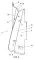
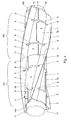
- a suppression element 1 has an envelope 2 with an exterior 21, which, in use, faces away from a tubular element, not shown, which, in use, is partly enveloped by the element 1.
- the element 1 On the exterior 21, the element 1 has a projection 3 pointing away from the envelopes, which reduces the formation of vortices on the downstream side of the tubular element.
- the projection is fin-shaped and has a triangular cross-section, the fin faces 31, 32 forming two sides of the triangle.
- the projection extends in the longitudinal direction A of the element 1 and lies at a non-right angle to the longitudinal direction, so that, as shown in Fig. 4 , the projections of several elements coupled to each other are together spirally or helically shaped.
- the suppression element according to the invention is modular.
- the shown example of a suppression element is, seen in the circumferential direction, not closed and can, together with other suppression elements, as shown in Fig. 4 , be composed to a tube, casing or shell closed in the circumferential direction, through which the tubular element can extend. Therefore, the envelope 2, transverse to the longitudinal direction, forms no closed, but an open contour, while several identical elements can be composed to a closed contour.
- the interior 22 and the exterior 21 of the element are unilaterally curved and not bent in the longitudinal direction.
- the envelope 2 occupies a circular arc of about 120 degrees, as indicated with B in the Figure.
- Three identical suppression elements according to the invention can thus completely envelop the circumference of the tube.
- the circular arc may also be slightly smaller or greater, such as between 120 and 117 degrees, and the circular arc may be, for instance, about 118.5 degrees.
- a damaged element can be readily replaced. For instance, in the example shown in Fig. 4 , a damaged element can be replaced by disconnecting the bands 9 in one of the segments 101, 102 and removing the damaged element. Subsequently, a new suppression element can be placed in the position of the damaged element, which placement can be accurately carried out with the aid of the directing means.
- the element can have a withdrawable form.
- the suppression element must be such that it has no undercuts in the mold.
- the faces 31, 32 of the projection 3 lie at an obtuse angle to an imaginary straight line C shown in Fig. 3 between the longitudinal sides of the suppression element.
- the straight line C is transverse to the longitudinal direction A and connects the ends of the circular arc with each other.
- the circular arc is smaller than 180 degrees.
- the example in Figs. 1-3 has a withdrawable form and can thus be manufactured with an appropriate mold, for instance in an injection molding process.
- the form of the example may be varied.
- the position and/or the form of the fin-shaped element and/or the curve of the envelope may be varied.
- the envelope may form a part of other tubular objects and, to this end, for instance, not be in the form of a circular arc transverse to the longitudinal direction, but, for instance, be a part of an ellipse, V-shaped or otherwise.
- Fig. 5 shows three elements 1a-1c according to the invention in a stacked condition.
- the volume is an important factor in the transport expenses, so that the shown example of an element according to the invention can be transported at low cost.
- the expenses are lower than with the known suppression elements, because the known suppression elements are circular in cross-section and, during transport thereof, a large empty volume is created, which is formed by the interior of the segment.
- the volume occupied during transport is further reduced because the interior 22 and the exterior 21 of the suppression elements 1a-1c have a corresponding form, so that the interior of one element can be placed close to the exterior of another element without much intermediate, wasted space.
- the suppression element 1 has spacers 4a-4d, which, in use, keep the tubular element and the envelope 2 at a distance from each other. It has been found that the known suppression systems accelerate the corrosion on the pipeline. Between the pipeline and the suppression element, in use, a film of still (sea)water is actually present, which accelerates this corrosion.
- the spacers 4a-4d in the shown example, a space is created between the tube and the envelope, through which water or another fluid can flow around or along the tube, as a result of which corrosion is inhibited.
- non-modular suppression elements may be provided with such spacers.
- the spacers form a recess of the surface of the interior 22 of the envelope 2, which interior, in mounted condition, is directed toward the tube.
- the spacers 4a, 4c and 4d form thickenings of the envelope 2 and are thus an integral part of the envelope 2.
- the spacer 4b also forms an integral part of the envelope 2. Consequently, the spacers can be manufactured already during the production of the envelope 2.
- the shown suppression element is at a distance from the tube which is smaller than 5 cm, such as smaller than 2 cm and may, for instance, range between 2 and 6 mm.
- spacers 4a and 4c are in an equal position as passages 5, which are described below in more detail.
- the spacer 4b is near a first end 10 of the element 1. Because of this placement of the spacers 4a-4c, the element, in use, is kept at a distance from the tube in a stable and safe manner.
- the spacer 4d Located on a longitudinal side of the element is the spacer 4d, the other longitudinal side has an identical spacer, not shown.
- the example of an element 1 according to the invention in Figs. 1-3 has passages 5, into and out of which the surrounding fluid, for instance water, can flow, so that the flow in the interspace between the tubular element and the suppression element is further increased.
- the passages 5 are at a transition of the envelope 2 in the projections 3.
- the form of the projection 3 is practically not disturbed by the location of the passages 5, so that optimum suppression of the vortex vibrations is obtained.
- the flow can also be strengthened by generating a flow with, for instance, a pumping device. For instance, at one of the ends 10, 11, water can be injected into the space between the tube and the suppression element 1, so that a flow is obtained in the longitudinal direction A.
- the passages 5 can also be used to provide fastening or connecting elements, such as, for instance, the bands 9 in Fig. 4 , which extend through the passages 5, and with which several elements can be composed to a segment, which completely surrounds the tubular element.
- the passages can of course also be used without the envelope being provided with spacers or with non-modular envelopes.
- the envelope 2 On the exterior 21, the envelope 2 has a recessed surface, which forms a nose 8 near the first end 10. At a second end 11, which, seen in the longitudinal direction A, is opposite the first end 10, the interior 22 of the element 1 has a recessed surface 6, which forms a shoulder being the negative of the nose 8.
- the ends 10, 11 of the element can thus connect to each other, so that the shown element 1 can be connected with a similar element.
- a suppression element without spacers or with a non-modular envelope can also be provided with such ends.
- the outer diameter of the envelope is diminished relative to the rest of the envelope 2.
- the inner diameter is enlarged relative to the rest of the envelope 2.
- the outer diameter of the element 1 is equal to the inner diameter at the second end 11.
- a similar suppression element can be placed with the first end on the second end of the shown example, a seal being obtained by the mutual overlap of the ends.
- the sealing effect can be further strengthened by, for instance, a glue or otherwise. The seal between the elements ensures that in case of damage to the tube the fluid transported through the tube, for instance oil or a gas, cannot freely spread.
- this preventive effect against soiling is further increased because the spacer 4b extends over the whole first end 10, as a result of which, in mounted condition, an assembly of such suppression elements is subdivided into compartments closed from each other.
- the passages 5 can be omitted, so that, in mounted condition, the envelope 2 of several elements can closedly envelop the tubular element.
- the nose 8 on the exterior 21 also extends over the fin-shaped projection 3, and near the second end 11 on the interior, this fin 3 has a form corresponding to the shoulder on the lower side.
- the interior 22 at the second end 11 in the fin 3 substantially has the same form as the exterior 21 at the first end 10 in the fin 3.
- the envelope 2 has a recess 7a on one of the longitudinal sides and a projection 7b corresponding to the recess on another longitudinal side opposing the one longitudinal side.
- the projection 7b projects in a direction transverse to the longitudinal direction. Because of the recess 7a and the projection 7b, several suppression elements, seen in the longitudinal direction, can be placed side by side, the elements not or at least hardly being able to move relative to each other when a force is exerted in the longitudinal direction. Also, the recess 7a and the projection 7b form directing means with which the suppression elements can be accurately placed relative to each other.
- the triangular cross-section of the projection 3 is an equilateral triangle, the mid-perpendicular H of which extends radially from the envelope 2 and has a height of a quarter of the diameter of the circular arc.
- the triangle may also have curved sides.
- the projection 3 is open toward the interior 22, which results in a good flow in the interspace. Also, the amount of material in the suppression element is thus reduced and hence the weight thereof.
- the example of an element according to the invention in Figs. 1-3 is provided with a marking 12, as a result of which the origin of the element can be determined. Also, the marking is provided with the manufacturer's address data, so that loosened elements can be taken in. The marking may be provided with a serial number, as a result of which it can be recorded with a database in a computer to which firm the element in question was delivered, so that, for instance, this firm can be automatically informed by the manufacturer that the element is lost.
- the shown suppression element has a specific density lower than the specific density of the surrounding fluid, so that the forces on the tube are reduced by the weight of the element and the tube.
- Such a measure can also be applied without the envelope being provided with spacers to maintain, in mounted condition, a space between the envelope and the tubular element.
- Buoyancy elements for tubular elements are known per se, for instance from International patent publication WO 99/05389 , US patent publication 6 048 136 . These have a density lower than that of water, but have the drawback that they occupy a large volume and thus disturb the flow around the tubular element. In particular, the large volume is often connected with a large approaching flow surface, as a result of which the water force on the upstream front side of the buoyancy element is great.
- the known buoyancy elements thus reduce the weight indeed, but simultaneously increase the flow forces. With a suppression element according to the invention having a specific density lower than water, the weight of the tubular element and envelope as well as the flow forces are reduced.
- the shown element is intended for use in water, in particular at sea, and has a specific density lower than that of water and more specifically a density between 0.8 and 0.9 kg per liter. Such a density has the advantage that the weight of the tubular element and the envelope is reduced, but not such that the whole is going to float.
- a suitable material for the manufacture of a suppression element is, for instance, a foamed plastic and, more in particular, a polyethylene (PE). Consequently, the element is not only light, but can also be manufactured from reused plastic, which is environmentally sound.
- Another suitable material is polypropylene (PP).
- Such a material has a good dimensional stability, also at higher temperatures, and can be used, for instance, for pipelines through which a fluid is transported at elevated temperature, for instance about 80°C.
- elevated temperature for instance about 80°C.
- the material may be designed completely or partly in a conspicuous color, such as, for instance, yellow.
- An element according to the invention may be elastically deformable, in particular by the use of PE or PP, but the elastic deformability may also be obtained in a different way. Because of the elastic deformability, little damage is caused to the element during placement. In fact, during placement the strake is often applied to the tube first, after which the tube is placed. The tube with the strake is often moved on rolls, a great force being locally exerted on the strake by the own weight of the strake as well as that of the tube. An elastically deformable element may thus deform elastically and will assume its original shape again when the pressure is removed. Such a measure can also be applied in suppression elements without spacers.
- a tubular element 100 is shown, such as, for instance, an oil pipeline, which is enveloped by a number of suppression elements 1, which are designed as the example of Figs. 1-3 .
- three suppression elements according to the invention each time form a cylindrical segment 101, 102 with three radial projections 3. Seen in a circumferential direction of the tubular element, the projections 3 are at an equal distance from each other, so that the vortex vibrations are suppressed independently of the approaching flow direction of the fluid.
- the projections 3 have a triangular cross-section and extend spirally in the longitudinal direction of the tubular element 100.
- the projections 3 have a rise between 5d and 20d, that is to say that it makes a revolution over a length of 5 to 20 times the diameter. Particularly suitable is a rise between 10d and 20d and more specifically between 12d and 18d, such as, for instance, 16d.
- the suppression elements 1 are connected with each other per segment 101, 102 by means of bands 9.
- the bands 9 extend through recesses, in the shown example passages 5, so that the bands cannot move relative to the suppression elements 1.
- the bands 9 lie against the envelopes 2, so that the bands do not appreciably disturb the flow around the segment. Such a measure can also be applied without the envelope being provided with spacers.
- each segment may have, for instance, a length of 1 m and a diameter of 33 cm. Seen in the radial direction, a space of about 2 to 6 mm may be present between the segments 101, 102 and the tube 100.
- the suppression elements may have a thickness ranging between 1.5 and 2.5 cm. At such a thickness, it has been found that the element can be readily manufactured and is sufficiently dimensionally stable.
- a suppression element in fields other than extraction of minerals, such as oil and gas.
- a suppression element may, for instance, also be applied to ship's masts, underwater cables, or otherwise.
- the projection or the fin differently and to provide, for instance, the faces 31, 32 with a curvature.
- the suppression element may also be multilaterally curved and, for instance, also be curved in the longitudinal direction, so that a bend in the pipeline can also be enveloped.
- the envelope may further not be curved at all and, for instance, be a flat plate which, together with other identical plates, can be composed to, for instance, a tube with a triangular, quadrangular, pentagonal, hexagonal or polygonal cross-section.
- the suppression element may be provided with one or more slots to reduce the force on the upstream surface.
- the word 'comprising' does not exclude that one or more elements other than those mentioned are present.
Landscapes
- Engineering & Computer Science (AREA)
- Mechanical Engineering (AREA)
- General Engineering & Computer Science (AREA)
- Geology (AREA)
- Mining & Mineral Resources (AREA)
- Physics & Mathematics (AREA)
- Fluid Mechanics (AREA)
- Combustion & Propulsion (AREA)
- Life Sciences & Earth Sciences (AREA)
- Ocean & Marine Engineering (AREA)
- Chemical & Material Sciences (AREA)
- General Life Sciences & Earth Sciences (AREA)
- Environmental & Geological Engineering (AREA)
- Geochemistry & Mineralogy (AREA)
- Pipe Accessories (AREA)
- Rigid Pipes And Flexible Pipes (AREA)
- Buildings Adapted To Withstand Abnormal External Influences (AREA)
- Respiratory Apparatuses And Protective Means (AREA)
- Vibration Prevention Devices (AREA)
- Percussion Or Vibration Massage (AREA)
- Physical Or Chemical Processes And Apparatus (AREA)
- Magnetic Ceramics (AREA)
- Orthopedics, Nursing, And Contraception (AREA)
Claims (25)
- Unterdrückungselement (1) für wirbelinduzierte Vibrationen, umfassend:- eine Hülle (2), die ein röhrenförmiges Element (100) zumindest teilweise umhüllt, wobei die Hülle ein Baustein ist, um in Umfangsrichtung des röhrenförmigen Elements (100) mit ähnlichen Unterdrückungselementen ein Rohr (101, 102) auszubilden, welches das röhrenförmigen Element im Betrieb zumindest teilweise umhüllt, und wobei das Unterdrückungselement (1) in einer Längsrichtung (A) des Unterdrückungselements (1) ein erstes Ende (10) in Längsrichtung (A) und ein entgegengesetztes Ende (11) in Längsrichtung (A) hat;- mindestens einen Vorsprung (3), der von der Hülle hinweg weist, um die Bildung von Wirbeln auf der stromabwärts gelegenen Seite des röhrenförmigen Elements (100) zu reduzieren, wobei sich der Vorsprung (3) in die Längsrichtung (A) erstreckt und in einem Winkel zu der Längsrichtung (A) liegt; und- ein Ausrichtungselement (6-8) zur Positionierung des Unterdrückungselements (1) relativ zu einem anderen ähnlichen Unterdrtickungselement, so dass das erste Ende (10) des Unterdrückungselements (1) an das zweite Ende (11) des anderen Unterdrückungselements angrenzt;wobei sich der Vorsprung (3) von einem ersten, in Längsrichtung (A) gelegenen Vorsprungsende des Vorsprungs (3) nahe dem ersten Ende (10) des Unterdrückungselements (1) zu einem zweiten, in Längsrichtung (A) gelegenen Vorsprungsende des Vorsprungs (3) nahe dem zweiten Ende (11) des Unterdrückungselements (1) erstreckt,
dadurch gekennzeichnet, dass das Ausrichtungselement (6-8) Mittel zur Positionierung des Vorsprungs (3) aufweist, derart dass sein erstes Vorsprungsende an ein zweites Vorsprungsende eines anderen ähnlichen Vorsprungs des anderen Unterdrückungselements angrenzt, wodurch ermöglicht wird, dass die Vorsprünge mehrerer Unterdrückungselemente miteinander in Verbindung gelangen, wodurch ein länglicher durchgehender Vorsprung erzielt werden kann, wobei sich längs angrenzende Unterdrückungselemente in Umfangsrichtung in versetzter Position relativ zueinander befinden. - Unterdrückungselement (1) nach Anspruch 1, das ferner mindestens einen Abstandhalter (4a-4d) aufweist, der im zusammengebauten Zustand einen Zwischenraum zwischen der Hülle (2) und dem röhrenförmigen Element (100) aufrechterhält.
- Unterdrückungselement (1) nach Anspruch 1 oder 2, das ferner mindestens einen Durchgang (5) in der Hülle (2) aufweist.
- Unterdrückungselement (1) nach Anspruch 3, bei welchem sich der Durchgang (5) mindestens teilweise durch den Vorsprung (3) erstreckt.
- Unterdrückungselement (1) nach Anspruch 3 oder 4, bei welchem der Durchgang (5) auch einen Durchgang für ein Verbindungselement (9) bildet.
- Unterdrückungselement (1) nach einem der Ansprüche 3-5, bei welchem der Durchgang (5) an einem Übergang zwischen der Hülle (2) und dem Vorsprung (3) ist.
- Unterdrückungselement (1) nach Anspruch 6, bei welchem die Oberfläche des Vorsprungs (3) in einem Winkel größer als oder gleich 90 Grad zu der Oberfläche der Hülle (2) liegt.
- Unterdrückungselement (1) nach Anspruch 6 oder 7, bei welchem die Hülle (2) unilateral gekrümmt um eine Längsrichtung (A) des Unterdrückungselements (1) ist.
- Unterdrückungselement (1) nach Anspruch 8, bei welchem die Hülle (2), quer zur Längsrichtung (A), im Wesentlichen die Form eines Kreisbogens hat.
- Unterdrückungselement (1) nach Anspruch 9, bei welchem die Hülle (2), in Längsrichtung (A) gesehen, einen Kreisbogen von 120 plus oder minus 3 Grad, wie z. B. 118,5 Grad, bildet.
- Unterdrückungselement (1) nach einem der vorhergehenden Ansprüche, bei welchem das Unterdrückungselement (1) einen Vorsprung (3) hat.
- Unterdrückungselement (1) nach einem der vorhergehenden Ansprüche, bei welchem der Vorsprung (3) einen dreieckigen Querschnitt hat.
- Unterdrückungselement (1) nach einem der vorhergehenden Ansprüche, bei welchem der Vorsprung (3) zu einer Seite in Richtung auf die Hülle (2) offen ist.
- Unterdrückungselement (1) nach einem der vorhergehenden Ansprüche, bei welchem das Innere (22) des Unterdrückungselements, welches im zusammengebauten Zustand auf das röhrenförmige Element (100) gerichtet ist, eine Form entsprechend einem Äußeren (21) des Unterdrückungselements hat, welches im zusammengebauten Zustand von dem röhrenförmigen Element (100) abgewandt ist.
- Unterdrückungselement (1) nach einem der vorhergehenden Ansprüche, welches aus einem Material hergestellt ist, das eine spezifische Dichte geringer als die von Wasser hat.
- Unterdrückungselement (1) nach Anspruch 15, bei welchem das Material eine spezifische Dichte zwischen 800 und 900 kg/cm3 hat.
- Unterdrückungselement (1) nach einem der vorhergehenden Ansprüche, das zumindest teilweise aus einem geschäumten Kunststoff hergestellt ist.
- Unterdrückungselement (1) nach einem der vorhergehenden Ansprüche, das zumindest teilweise aus wiederverwerteten Kunststoff hergestellt ist.
- Unterdrückungselement (1) nach einem der vorhergehenden Ansprüche, das zumindest teilweise aus Polyäthylen oder Polypropylen hergestellt ist.
- Unterdrückungselement (1) nach einem der vorhergehenden Ansprüche, das ferner eine Ursprungskennzeichnung (12) aufweist.
- Bausatz für ein Unterdrückungssystem, der mindestens zwei Unterdrückungselemente (1) nach einem der vorhergehenden Ansprüche aufweist.
- Unterdrückungssystem für wirbelinduzierte Vibrationen, das mindestens zwei Unterdrückungselemente (1) nach einem der vorhergehenden Ansprüche 1-20 aufweist, welche zusammen eine Röhre bilden, die im Betrieb zumindest teilweise ein röhrenförmige Element. (100) umhüllt.
- Unterdrückungssystem für wirbelinduzierte Vibrationen nach Anspruch 22, das ferner ein Strömungselement (5) aufweist, das eine Fluidströmung in den Raum zwischen dem röhrenförmigen Element (100) und den Unterdrückungselementen (1) vorsieht.
- Vorrichtung zur Extraktion von Mineralien, umfassen:eine Plattform, welche sich im oder am Wasser befindet,ein Unterdrückungselement (1) gemäß einem oder mehreren der Ansprüche 1-20, undmindestens eine Pipeline (100), die sich von der Plattform in das Wasser erstreckt, wobei ein Teil der im Wasser befindlichen Pipeline zumindest teilweise von dem Unterdrückungselement (1) umhüllt ist.
- Form zur Herstellung eines Unterdrückungselements (1) nach einem der Ansprüche 1-19.
Applications Claiming Priority (3)
| Application Number | Priority Date | Filing Date | Title |
|---|---|---|---|
| NL1021347A NL1021347C2 (nl) | 2002-08-28 | 2002-08-28 | Suppressie-element voor wervelvibraties, bouwpakket, suppressiestelsel, inrichting voor het winnen van delfstoffen en een matrijs. |
| NL1021347 | 2002-08-28 | ||
| PCT/NL2003/000599 WO2004020777A1 (en) | 2002-08-28 | 2003-08-26 | Suppression element for vortex-induced vibrations, construction kit, apparatus for extracting minerals, and mold |
Publications (2)
| Publication Number | Publication Date |
|---|---|
| EP1534919A1 EP1534919A1 (de) | 2005-06-01 |
| EP1534919B1 true EP1534919B1 (de) | 2010-03-31 |
Family
ID=31973729
Family Applications (1)
| Application Number | Title | Priority Date | Filing Date |
|---|---|---|---|
| EP03791490A Expired - Lifetime EP1534919B1 (de) | 2002-08-28 | 2003-08-26 | Unterdrückungselement für wirbelinduzierte vibrationen, konstruktionsausrüstung, vorrichtung zum extrahieren von mineralien und formwerkzeug |
Country Status (9)
| Country | Link |
|---|---|
| US (1) | US7458752B2 (de) |
| EP (1) | EP1534919B1 (de) |
| AT (1) | ATE462865T1 (de) |
| AU (1) | AU2003261018A1 (de) |
| BR (1) | BR0313929B1 (de) |
| DE (1) | DE60331924D1 (de) |
| NL (1) | NL1021347C2 (de) |
| NO (1) | NO333051B1 (de) |
| WO (1) | WO2004020777A1 (de) |
Families Citing this family (44)
| Publication number | Priority date | Publication date | Assignee | Title |
|---|---|---|---|---|
| US6953308B1 (en) * | 2004-05-12 | 2005-10-11 | Deepwater Technologies, Inc. | Offshore platform stabilizing strakes |
| NO321539B1 (no) * | 2005-03-15 | 2006-05-22 | Statoil Asa | Vibrasjonsdemper |
| BRPI0610116A2 (pt) * | 2005-05-24 | 2019-04-09 | Shell Int Research | aparelho, e, método para instalar elementos de tira |
| WO2007108693A1 (en) * | 2006-03-21 | 2007-09-27 | Statoil Asa | Vibration reducer for reducing flow induced vibrations in a pipe and method of reducing such vibrations |
| WO2007128029A1 (en) * | 2006-05-03 | 2007-11-15 | Barnacle Guard (Australia) Pty Ltd | Marine pile anti-fouling device |
| GB2445751B (en) * | 2007-01-17 | 2009-02-25 | Trelleborg Crp Ltd | Fairing |
| GB2458110A (en) * | 2008-03-03 | 2009-09-09 | Trelleborg Crp Ltd | Mould for forming vortex inducing suppression features on an elongate member |
| US8167514B2 (en) * | 2009-08-21 | 2012-05-01 | Seahorse Equipment Corporation | Strake system for submerged or partially submerged structures |
| WO2011041860A1 (pt) * | 2009-10-09 | 2011-04-14 | Petróleo Brasileiro S.A. - Petrobras | Amortecedor hidrodinâmico para tubo ascendente em catenária |
| NL2005866C2 (nl) | 2010-12-16 | 2012-06-19 | Lankhorst Mouldings B V | Omhullingselement voor een pijpleiding, alsmede matrijs voor vervaardiging daarvan. |
| US9511825B1 (en) * | 2011-01-05 | 2016-12-06 | VIV Solutions LLC | Apparatus for suppressing vortex-induced vibration of a structure with reduced coverage |
| US8511245B2 (en) * | 2011-05-16 | 2013-08-20 | VIV Solutions LLC | Helical strake systems |
| US8770894B1 (en) | 2011-12-27 | 2014-07-08 | VIV Solutions LLC | Helical strakes with molded in stand-offs |
| GB201205059D0 (en) * | 2012-03-22 | 2012-05-09 | Trelleborg Offshore U K Ltd | Cladding |
| US20140007523A1 (en) * | 2012-07-06 | 2014-01-09 | Thomas & Betts International, Inc. | Strakes for utility structures |
| US8944722B1 (en) | 2012-10-10 | 2015-02-03 | VIV Solutions, LLC | Spring systems for vortex suppression devices |
| US9869128B1 (en) | 2012-11-24 | 2018-01-16 | VIV Solutions LLC | Installation systems and methodology for helical strake fins |
| US9523247B1 (en) * | 2013-03-05 | 2016-12-20 | VIV Solutions LLC | Spaced VIV suppression system |
| EP2851490B1 (de) | 2013-09-20 | 2017-03-29 | Siemens Aktiengesellschaft | Transport eines Turms einer Windturbine |
| US9546523B1 (en) | 2014-06-06 | 2017-01-17 | VIV Solutions LLC | Collars for multiple tubulars |
| NL2013829B1 (en) * | 2014-11-19 | 2016-10-11 | Lankhorst Eng Products B V | Twin-fin fairing. |
| DK3029313T3 (en) * | 2014-12-04 | 2018-05-07 | Siemens Ag | Strake for a windmill tower |
| US10865910B1 (en) | 2015-04-17 | 2020-12-15 | VIV Solutions LLC | Coupled fairing systems |
| CN105134138A (zh) * | 2015-09-07 | 2015-12-09 | 中山乐满石油设备有限公司 | 一种用于井下涡流工具的密封机构 |
| US10337649B1 (en) | 2016-03-02 | 2019-07-02 | VIV Solutions LLC | Strake system |
| CN105604500A (zh) * | 2016-03-11 | 2016-05-25 | 青岛迪玛尔海洋工程有限公司 | 水下立管涡激振动抑制装置 |
| AU2017272811B2 (en) | 2016-06-02 | 2019-07-25 | Shell Internationale Research Maatschappij B.V. | Vortex induced suppression device |
| CN105927479B (zh) * | 2016-06-20 | 2019-05-07 | 新疆金风科技股份有限公司 | 风力发电机组的安装方法 |
| US10473131B1 (en) | 2016-07-10 | 2019-11-12 | VIV Solutions LLC | Helical strakes and collar |
| US10808683B2 (en) * | 2016-11-07 | 2020-10-20 | Siemens Gamesa Renewable Energy A/S | Vortex-shedding-arrangement |
| NL2019077B1 (en) * | 2017-06-15 | 2018-12-24 | Bluemarine Offshore Yard Service Bv | VIV suppression strake assembly |
| US10669785B1 (en) | 2017-08-30 | 2020-06-02 | VIV Solutions LLC | VIV suppression devices with buoyancy modules |
| US11261675B2 (en) | 2018-01-16 | 2022-03-01 | VIV Solutions LLC | Methods for constructing a helical strake segment using one or more shell sections and fins |
| US10900296B2 (en) * | 2018-04-11 | 2021-01-26 | CBM International, Inc. | Methods and systems for VIV suppression utilizing retractable fins |
| CN108799010B (zh) * | 2018-06-21 | 2020-10-09 | 北京金风科创风电设备有限公司 | 外表面设有混频吸收器的围护结构 |
| US11353153B2 (en) * | 2018-10-18 | 2022-06-07 | Meyer Utility Structures Llc | Helical strake attachment for tubular structural members |
| NL2023435B1 (nl) | 2019-07-04 | 2021-02-02 | Lankhorst Eng Products B V | Suppressie-element voor wervelvibraties. |
| US11261670B1 (en) * | 2019-07-08 | 2022-03-01 | VIV Solutions LLC | VIV suppression for retrofit with minimal tooling |
| CN111188815B (zh) * | 2020-02-08 | 2021-11-23 | 西南石油大学 | 一种大头鱼形开槽导流喷射与摆尾的抑振装置及方法 |
| GB2592072B (en) * | 2020-02-17 | 2024-07-17 | Trelleborg Offshore Uk Ltd | Cladding |
| US11585321B2 (en) * | 2020-10-28 | 2023-02-21 | General Electric Company | Method and system for attaching vortex suppression devices to a wind turbine tower |
| CN114482876A (zh) * | 2021-12-31 | 2022-05-13 | 海油发展珠海管道工程有限公司 | 一种用于深水立管的螺旋列板涡激振动抑制装置 |
| EP4283139A1 (de) * | 2022-05-24 | 2023-11-29 | Advanced Innergy Ltd | Rippenanordnungen gegen wirbel-induzierte schwingungen |
| EP4728163A2 (de) * | 2023-07-13 | 2026-04-22 | Oceaneering International, Inc. | Nachrüstbare vorrichtung zur unterdrückung von wirbelinduzierter vibration (viv) |
Family Cites Families (12)
| Publication number | Priority date | Publication date | Assignee | Title |
|---|---|---|---|---|
| GB2153962A (en) * | 1984-02-04 | 1985-08-29 | British Petroleum Co Plc | Riser shroud |
| US5421413A (en) | 1993-11-02 | 1995-06-06 | Shell Oil Company | Flexible fairings to reduce vortex-induced vibrations |
| US5984584A (en) * | 1996-05-10 | 1999-11-16 | Shell Oil Company | Fairings for drilling riser control pod hoses |
| US6347911B1 (en) | 1996-06-11 | 2002-02-19 | Slickbar Products Corp. | Vortex shedding strake wraps for submerged pilings and pipes |
| US6048136A (en) * | 1996-07-19 | 2000-04-11 | Shell Oil Company | Vortex induced vibration protection for deepwater drilling risers |
| WO1999005389A1 (en) * | 1997-07-23 | 1999-02-04 | Cuming Corporation | A floating system for a marine riser |
| GB2378493B (en) * | 1998-03-07 | 2003-04-09 | Crp Group Ltd | Protection of underwater elongate members |
| GB0008805D0 (en) * | 2000-04-10 | 2000-05-31 | Sugiyama Toru C O Smc K K Tsuk | Protection of underwater elongate members |
| US6401646B1 (en) * | 2000-09-14 | 2002-06-11 | Aims International, Inc. | Snap-on rotating reduction fairing |
| US6896447B1 (en) * | 2000-11-14 | 2005-05-24 | Weldon Taquino | Vortex induced vibration suppression device and method |
| NL1016610C2 (nl) * | 2000-11-15 | 2002-05-16 | Lankhorst Recycling Bv | Beschermelement voor een stijgbuissegment. |
| GB0321404D0 (en) * | 2003-09-12 | 2003-10-15 | Crp Group Ltd | Vacuum formed cladding |
-
2002
- 2002-08-28 NL NL1021347A patent/NL1021347C2/nl not_active IP Right Cessation
-
2003
- 2003-08-26 AT AT03791490T patent/ATE462865T1/de not_active IP Right Cessation
- 2003-08-26 EP EP03791490A patent/EP1534919B1/de not_active Expired - Lifetime
- 2003-08-26 WO PCT/NL2003/000599 patent/WO2004020777A1/en not_active Ceased
- 2003-08-26 DE DE60331924T patent/DE60331924D1/de not_active Expired - Lifetime
- 2003-08-26 US US10/526,142 patent/US7458752B2/en not_active Expired - Fee Related
- 2003-08-26 BR BRPI0313929-8B1A patent/BR0313929B1/pt not_active IP Right Cessation
- 2003-08-26 AU AU2003261018A patent/AU2003261018A1/en not_active Abandoned
-
2005
- 2005-03-23 NO NO20051554A patent/NO333051B1/no not_active IP Right Cessation
Also Published As
| Publication number | Publication date |
|---|---|
| US20060153642A1 (en) | 2006-07-13 |
| BR0313929A (pt) | 2005-07-12 |
| ATE462865T1 (de) | 2010-04-15 |
| NO333051B1 (no) | 2013-02-18 |
| BR0313929B1 (pt) | 2014-04-29 |
| NO20051554L (no) | 2005-05-20 |
| NL1021347C2 (nl) | 2004-03-02 |
| US7458752B2 (en) | 2008-12-02 |
| DE60331924D1 (de) | 2010-05-12 |
| AU2003261018A1 (en) | 2004-03-19 |
| EP1534919A1 (de) | 2005-06-01 |
| WO2004020777A1 (en) | 2004-03-11 |
Similar Documents
| Publication | Publication Date | Title |
|---|---|---|
| EP1534919B1 (de) | Unterdrückungselement für wirbelinduzierte vibrationen, konstruktionsausrüstung, vorrichtung zum extrahieren von mineralien und formwerkzeug | |
| US7600945B2 (en) | Vacuum formed cladding | |
| US6401646B1 (en) | Snap-on rotating reduction fairing | |
| CN101387188B (zh) | 海洋立管涡激振动的抑振方法及其抑振装置 | |
| US8579546B2 (en) | Apparatus and method for inhibiting vortex-induced vibration | |
| US6755595B2 (en) | Riser impact protection | |
| US20160230476A1 (en) | Riser floatation with anti-vibration strakes | |
| EP2379895B1 (de) | Unterdrückung vortexinduzierter vibrationen (viv) von hebevorrichtungen | |
| US20020168232A1 (en) | Vortex-induced vibration reduction device for fluid immersed cylinders | |
| US20040013473A1 (en) | Protection of underwater elongate members | |
| JPS58588A (ja) | 深水用ライザ− | |
| BR112014032660B1 (pt) | carcaça de tubo para controlar vibração induzida por fluxo em tubo ascendente | |
| US8152414B2 (en) | Device and method for suppressing vortex-induced vibrations | |
| JP7249329B2 (ja) | 渦励振(viv)および/または抗力を低減するようにプロファイルされた円筒形要素 | |
| BR112015002632B1 (pt) | corpo de tubo flexível e método de fornecimento do mesmo | |
| CN105378213A (zh) | 管部件及制造方法 | |
| BR112015002633B1 (pt) | corpo de tubo flexível e método de fornecimento do mesmo | |
| US10344785B1 (en) | Multiple component fairing | |
| CN114482876A (zh) | 一种用于深水立管的螺旋列板涡激振动抑制装置 | |
| GB2362444A (en) | Protection of underwater elongate members | |
| GB2378969A (en) | Vortex-induced vibration suppression | |
| US20080286052A1 (en) | Device for Maintaining Very Long Tubes or Pipelines in Position and Damping Same in Relation to Fixed Support Structures | |
| AU2017272811B2 (en) | Vortex induced suppression device | |
| KR20250166100A (ko) | 부력 모듈 | |
| JPS6223760Y2 (de) |
Legal Events
| Date | Code | Title | Description |
|---|---|---|---|
| PUAI | Public reference made under article 153(3) epc to a published international application that has entered the european phase |
Free format text: ORIGINAL CODE: 0009012 |
|
| 17P | Request for examination filed |
Effective date: 20050311 |
|
| AK | Designated contracting states |
Kind code of ref document: A1 Designated state(s): AT BE BG CH CY CZ DE DK EE ES FI FR GB GR HU IE IT LI LU MC NL PT RO SE SI SK TR |
|
| AX | Request for extension of the european patent |
Extension state: AL LT LV MK |
|
| DAX | Request for extension of the european patent (deleted) | ||
| GRAP | Despatch of communication of intention to grant a patent |
Free format text: ORIGINAL CODE: EPIDOSNIGR1 |
|
| GRAS | Grant fee paid |
Free format text: ORIGINAL CODE: EPIDOSNIGR3 |
|
| GRAA | (expected) grant |
Free format text: ORIGINAL CODE: 0009210 |
|
| AK | Designated contracting states |
Kind code of ref document: B1 Designated state(s): AT BE BG CH CY CZ DE DK EE ES FI FR GB GR HU IE IT LI LU MC NL PT RO SE SI SK TR |
|
| REG | Reference to a national code |
Ref country code: GB Ref legal event code: FG4D Ref country code: CH Ref legal event code: EP |
|
| REG | Reference to a national code |
Ref country code: IE Ref legal event code: FG4D |
|
| REF | Corresponds to: |
Ref document number: 60331924 Country of ref document: DE Date of ref document: 20100512 Kind code of ref document: P |
|
| REG | Reference to a national code |
Ref country code: NL Ref legal event code: T3 |
|
| PG25 | Lapsed in a contracting state [announced via postgrant information from national office to epo] |
Ref country code: AT Free format text: LAPSE BECAUSE OF FAILURE TO SUBMIT A TRANSLATION OF THE DESCRIPTION OR TO PAY THE FEE WITHIN THE PRESCRIBED TIME-LIMIT Effective date: 20100331 Ref country code: FI Free format text: LAPSE BECAUSE OF FAILURE TO SUBMIT A TRANSLATION OF THE DESCRIPTION OR TO PAY THE FEE WITHIN THE PRESCRIBED TIME-LIMIT Effective date: 20100331 Ref country code: SI Free format text: LAPSE BECAUSE OF FAILURE TO SUBMIT A TRANSLATION OF THE DESCRIPTION OR TO PAY THE FEE WITHIN THE PRESCRIBED TIME-LIMIT Effective date: 20100331 |
|
| PG25 | Lapsed in a contracting state [announced via postgrant information from national office to epo] |
Ref country code: RO Free format text: LAPSE BECAUSE OF FAILURE TO SUBMIT A TRANSLATION OF THE DESCRIPTION OR TO PAY THE FEE WITHIN THE PRESCRIBED TIME-LIMIT Effective date: 20100331 Ref country code: EE Free format text: LAPSE BECAUSE OF FAILURE TO SUBMIT A TRANSLATION OF THE DESCRIPTION OR TO PAY THE FEE WITHIN THE PRESCRIBED TIME-LIMIT Effective date: 20100331 Ref country code: SE Free format text: LAPSE BECAUSE OF FAILURE TO SUBMIT A TRANSLATION OF THE DESCRIPTION OR TO PAY THE FEE WITHIN THE PRESCRIBED TIME-LIMIT Effective date: 20100331 Ref country code: BE Free format text: LAPSE BECAUSE OF FAILURE TO SUBMIT A TRANSLATION OF THE DESCRIPTION OR TO PAY THE FEE WITHIN THE PRESCRIBED TIME-LIMIT Effective date: 20100331 Ref country code: CY Free format text: LAPSE BECAUSE OF FAILURE TO SUBMIT A TRANSLATION OF THE DESCRIPTION OR TO PAY THE FEE WITHIN THE PRESCRIBED TIME-LIMIT Effective date: 20100331 Ref country code: ES Free format text: LAPSE BECAUSE OF FAILURE TO SUBMIT A TRANSLATION OF THE DESCRIPTION OR TO PAY THE FEE WITHIN THE PRESCRIBED TIME-LIMIT Effective date: 20100712 |
|
| PG25 | Lapsed in a contracting state [announced via postgrant information from national office to epo] |
Ref country code: CZ Free format text: LAPSE BECAUSE OF FAILURE TO SUBMIT A TRANSLATION OF THE DESCRIPTION OR TO PAY THE FEE WITHIN THE PRESCRIBED TIME-LIMIT Effective date: 20100331 Ref country code: SK Free format text: LAPSE BECAUSE OF FAILURE TO SUBMIT A TRANSLATION OF THE DESCRIPTION OR TO PAY THE FEE WITHIN THE PRESCRIBED TIME-LIMIT Effective date: 20100331 |
|
| PG25 | Lapsed in a contracting state [announced via postgrant information from national office to epo] |
Ref country code: DK Free format text: LAPSE BECAUSE OF FAILURE TO SUBMIT A TRANSLATION OF THE DESCRIPTION OR TO PAY THE FEE WITHIN THE PRESCRIBED TIME-LIMIT Effective date: 20100331 Ref country code: PT Free format text: LAPSE BECAUSE OF FAILURE TO SUBMIT A TRANSLATION OF THE DESCRIPTION OR TO PAY THE FEE WITHIN THE PRESCRIBED TIME-LIMIT Effective date: 20100802 |
|
| PLBE | No opposition filed within time limit |
Free format text: ORIGINAL CODE: 0009261 |
|
| STAA | Information on the status of an ep patent application or granted ep patent |
Free format text: STATUS: NO OPPOSITION FILED WITHIN TIME LIMIT |
|
| 26N | No opposition filed |
Effective date: 20110104 |
|
| PG25 | Lapsed in a contracting state [announced via postgrant information from national office to epo] |
Ref country code: MC Free format text: LAPSE BECAUSE OF NON-PAYMENT OF DUE FEES Effective date: 20100831 |
|
| REG | Reference to a national code |
Ref country code: CH Ref legal event code: PL |
|
| PG25 | Lapsed in a contracting state [announced via postgrant information from national office to epo] |
Ref country code: LI Free format text: LAPSE BECAUSE OF NON-PAYMENT OF DUE FEES Effective date: 20100831 Ref country code: CH Free format text: LAPSE BECAUSE OF NON-PAYMENT OF DUE FEES Effective date: 20100831 |
|
| REG | Reference to a national code |
Ref country code: DE Ref legal event code: R119 Ref document number: 60331924 Country of ref document: DE Effective date: 20110301 |
|
| PG25 | Lapsed in a contracting state [announced via postgrant information from national office to epo] |
Ref country code: DE Free format text: LAPSE BECAUSE OF NON-PAYMENT OF DUE FEES Effective date: 20110301 Ref country code: IE Free format text: LAPSE BECAUSE OF NON-PAYMENT OF DUE FEES Effective date: 20100826 |
|
| PG25 | Lapsed in a contracting state [announced via postgrant information from national office to epo] |
Ref country code: HU Free format text: LAPSE BECAUSE OF FAILURE TO SUBMIT A TRANSLATION OF THE DESCRIPTION OR TO PAY THE FEE WITHIN THE PRESCRIBED TIME-LIMIT Effective date: 20101001 Ref country code: BG Free format text: LAPSE BECAUSE OF FAILURE TO SUBMIT A TRANSLATION OF THE DESCRIPTION OR TO PAY THE FEE WITHIN THE PRESCRIBED TIME-LIMIT Effective date: 20100331 Ref country code: LU Free format text: LAPSE BECAUSE OF NON-PAYMENT OF DUE FEES Effective date: 20100826 |
|
| PG25 | Lapsed in a contracting state [announced via postgrant information from national office to epo] |
Ref country code: TR Free format text: LAPSE BECAUSE OF FAILURE TO SUBMIT A TRANSLATION OF THE DESCRIPTION OR TO PAY THE FEE WITHIN THE PRESCRIBED TIME-LIMIT Effective date: 20100331 |
|
| PG25 | Lapsed in a contracting state [announced via postgrant information from national office to epo] |
Ref country code: BG Free format text: LAPSE BECAUSE OF FAILURE TO SUBMIT A TRANSLATION OF THE DESCRIPTION OR TO PAY THE FEE WITHIN THE PRESCRIBED TIME-LIMIT Effective date: 20100630 |
|
| PG25 | Lapsed in a contracting state [announced via postgrant information from national office to epo] |
Ref country code: GR Free format text: LAPSE BECAUSE OF FAILURE TO SUBMIT A TRANSLATION OF THE DESCRIPTION OR TO PAY THE FEE WITHIN THE PRESCRIBED TIME-LIMIT Effective date: 20100331 |
|
| REG | Reference to a national code |
Ref country code: FR Ref legal event code: PLFP Year of fee payment: 13 |
|
| REG | Reference to a national code |
Ref country code: FR Ref legal event code: PLFP Year of fee payment: 14 |
|
| REG | Reference to a national code |
Ref country code: FR Ref legal event code: PLFP Year of fee payment: 15 |
|
| PGFP | Annual fee paid to national office [announced via postgrant information from national office to epo] |
Ref country code: NL Payment date: 20170728 Year of fee payment: 15 |
|
| PGFP | Annual fee paid to national office [announced via postgrant information from national office to epo] |
Ref country code: GB Payment date: 20170822 Year of fee payment: 15 Ref country code: IT Payment date: 20170828 Year of fee payment: 15 Ref country code: FR Payment date: 20170822 Year of fee payment: 15 |
|
| REG | Reference to a national code |
Ref country code: NL Ref legal event code: MM Effective date: 20180901 |
|
| GBPC | Gb: european patent ceased through non-payment of renewal fee |
Effective date: 20180826 |
|
| PG25 | Lapsed in a contracting state [announced via postgrant information from national office to epo] |
Ref country code: NL Free format text: LAPSE BECAUSE OF NON-PAYMENT OF DUE FEES Effective date: 20180901 |
|
| PG25 | Lapsed in a contracting state [announced via postgrant information from national office to epo] |
Ref country code: IT Free format text: LAPSE BECAUSE OF NON-PAYMENT OF DUE FEES Effective date: 20180826 |
|
| PG25 | Lapsed in a contracting state [announced via postgrant information from national office to epo] |
Ref country code: FR Free format text: LAPSE BECAUSE OF NON-PAYMENT OF DUE FEES Effective date: 20180831 |
|
| PG25 | Lapsed in a contracting state [announced via postgrant information from national office to epo] |
Ref country code: GB Free format text: LAPSE BECAUSE OF NON-PAYMENT OF DUE FEES Effective date: 20180826 |