EP1534518B1 - Support system and method for a screen printing unit - Google Patents
Support system and method for a screen printing unit Download PDFInfo
- Publication number
- EP1534518B1 EP1534518B1 EP03760079.8A EP03760079A EP1534518B1 EP 1534518 B1 EP1534518 B1 EP 1534518B1 EP 03760079 A EP03760079 A EP 03760079A EP 1534518 B1 EP1534518 B1 EP 1534518B1
- Authority
- EP
- European Patent Office
- Prior art keywords
- printing
- screen
- printing screen
- tensioning
- support system
- Prior art date
- Legal status (The legal status is an assumption and is not a legal conclusion. Google has not performed a legal analysis and makes no representation as to the accuracy of the status listed.)
- Expired - Lifetime
Links
Images

















Classifications
-
- H—ELECTRICITY
- H05—ELECTRIC TECHNIQUES NOT OTHERWISE PROVIDED FOR
- H05K—PRINTED CIRCUITS; CASINGS OR CONSTRUCTIONAL DETAILS OF ELECTRIC APPARATUS; MANUFACTURE OF ASSEMBLAGES OF ELECTRICAL COMPONENTS
- H05K3/00—Apparatus or processes for manufacturing printed circuits
- H05K3/10—Apparatus or processes for manufacturing printed circuits in which conductive material is applied to the insulating support in such a manner as to form the desired conductive pattern
- H05K3/12—Apparatus or processes for manufacturing printed circuits in which conductive material is applied to the insulating support in such a manner as to form the desired conductive pattern using thick film techniques, e.g. printing techniques to apply the conductive material or similar techniques for applying conductive paste or ink patterns
- H05K3/1216—Apparatus or processes for manufacturing printed circuits in which conductive material is applied to the insulating support in such a manner as to form the desired conductive pattern using thick film techniques, e.g. printing techniques to apply the conductive material or similar techniques for applying conductive paste or ink patterns by screen printing or stencil printing
- H05K3/1225—Screens or stencils; Holders therefor
-
- B—PERFORMING OPERATIONS; TRANSPORTING
- B41—PRINTING; LINING MACHINES; TYPEWRITERS; STAMPS
- B41F—PRINTING MACHINES OR PRESSES
- B41F15/00—Screen printers
- B41F15/14—Details
- B41F15/34—Screens, Frames; Holders therefor
-
- B—PERFORMING OPERATIONS; TRANSPORTING
- B41—PRINTING; LINING MACHINES; TYPEWRITERS; STAMPS
- B41F—PRINTING MACHINES OR PRESSES
- B41F15/00—Screen printers
- B41F15/14—Details
- B41F15/34—Screens, Frames; Holders therefor
- B41F15/36—Screens, Frames; Holders therefor flat
-
- B—PERFORMING OPERATIONS; TRANSPORTING
- B41—PRINTING; LINING MACHINES; TYPEWRITERS; STAMPS
- B41P—INDEXING SCHEME RELATING TO PRINTING, LINING MACHINES, TYPEWRITERS, AND TO STAMPS
- B41P2215/00—Screen printing machines
- B41P2215/10—Screen printing machines characterised by their constructional features
- B41P2215/14—Devices or methods for reducing snap effect
Definitions
- the present invention relates to a support system for and a method of supporting a printing screen unit comprising a printing screen, often alternatively referred to as a printing stencil, in a screen printing operation.
- a printing screen includes a pattern of printing apertures which defines the pattern of deposits to be printed in a screen printing operation, with the printing screen being located over a workpiece to be printed and printing medium being forced through the printing apertures to provide the required print.
- the printing screen comprises a thin sheet, typically a metal or plastics sheet, which includes a plurality of printing apertures which define a pattern for the printing of deposits of a printing medium.
- the printing screens are tensioned to a very high tension to prevent lateral, that is, in-plane, movement during the printing phase of a screen printing operation.
- the printing screen is mounted to a rigid frame by a woven fabric which acts to tension the printing screen to the required high tension.
- a woven fabric is stretched to the required high tension over a rigid frame and bonded thereto, and the periphery of the printing screen is bonded to the stretched fabric which is then removed in the operative region of the printing screen to maintain the printing screen under the required tension.
- the printing screen is mounted to a rigid frame by mechanical tensioning mechanisms which engage fixing apertures at the periphery of the printing screen and act to tension the printing screen to the required high tension, with the tensioning force typically being provided by hydraulic, pneumatic or spring means.
- WO-A-93/25061 discloses one tensioning system in which the printing screen includes a plurality of elongate slots, as the fixing apertures, along each of opposite edges thereof, and the tensioning mechanisms each include a set of teeth which engage the slots at respective ones of the opposite edges of the printing screen to tension the printing screen to the required high tension, with the tensioning mechanisms being configured to draw respective ones of the opposite edges of the printing screen over respective supporting edges of the frame and thereby maintain the printing screen at the required high tension.
- GB-A-2364961 discloses another tensioning system in which the printing screen includes a plurality of first, fixing apertures along each of opposite edges thereof which are engaged by respective tensioning mechanisms, and a plurality of second, flexing apertures along each of the opposite edges thereof which extend inwardly of the respective fixing apertures and provide for regions of increased flexibility, with the tensioning mechanisms being configured to draw respective ones of the opposite edges of the printing screen over respective supporting edges of the frame and thereby maintain the printing screen at the required high tension.
- a high separation force is required to separate a printing screen from a workpiece because of the adhesive effect of the printing medium, with the printing medium in the printing apertures adhering both to the underlying workpiece and the edges of the printing apertures. This is particularly the case for printing screens which include increased numbers of printing apertures, and especially where the printing apertures are of smaller size and hence have an increased edge-to-area ratio, as is the current trend.
- the separation force required to separate a printing screen from a workpiece is so great as to cause the printing screen to flex, with the separation of the printing screen from the workpiece being effected in part as a peeling action from the periphery to the center of the printing screen.
- This out-of-plane deflection of the printing screen creates localized stresses in the printing screen at the peeling fronts. These stresses cause micro-displacement of the printing screen, which acts to cause deformation, notably shearing, of the printed deposits at the peeling fronts in separating the printing screen from the workpiece. In addition, these stresses can act to cause localized deformation of the printing screen, particularly the very thin printing screens as used in wafer bumping, with this deformation acting to wrinkle the printing screen. As will be understood, wrinkled printing screens cannot provide for high-quality prints; printing screens being required to present an essentially flat surface to workpieces.
- tensioning systems have been proposed which provide for an increased speed of separation. Such systems do provide for the instantaneous separation of a larger area of a printing screen, and thereby diminishes the out-of-plane effect, which causes shearing of the printed deposits, but such separation is even more uncontrolled.
- the present invention provides a support system for supporting a printing screen unit in a screen printing machine, the support system including: a support assembly comprising a support unit for supporting the printing screen unit comprising a printing screen including printing apertures through which printing medium is in use printed onto a workpiece; and a tensioning mechanism for tensioning the printing screen in a screen printing operation; and a control unit for controlling operation of the support assembly, wherein the control unit is configured to operate the tensioning mechanism to tension the printing screen to a first tension in a printing phase in printing printing medium onto the workpiece and a second tension, which is lower than the first tension, in a separation phase in separating the printing screen unit and the workpiece.
- the second tension is substantially a zero tension.
- the tensioning mechanism comprises at least first and second tensioning units for tensioning the printing screen.
- the tensioning units are configured to apply a tensioning force to opposite edges of the printing screen.
- tensioning units are configured to apply tensioning forces to adjacent corners of the printing screen.
- the tensioning units are configured to apply the tensioning forces along intersecting axes.
- the axes intersect at the center of the printing screen.
- the tensioning mechanism comprises four tensioning units each for applying a tensioning force to a respective corner of the printing screen.
- the tensioning units are configured to apply tensioning forces along intersecting axes.
- the axes intersect at the center of the printing screen.
- the support unit comprises first and second screen guiding units for guiding the printing screen which are disposed to opposite edges of the printing screen.
- the screen guiding units act to constrain deflection of the printing screen in the separation phase.
- the screen guiding units are disposed to ends of the printing screen in the direction of screen printing.
- the screen guiding units are disposed to sides of the printing screen in the direction of screen printing.
- the support assembly comprises a clamping mechanism for clamping the printing screen in the printing phase so as to fix the lateral, in-plane position of the printing screen.
- the clamping mechanism comprises first and second screen clamping units disposed to opposite edges of the printing screen.
- the screen clamping units are disposed to opposite ends of the printing screen in the direction of screen printing.
- the screen clamping units are disposed to opposite sides of the printing screen in the direction of screen printing.
- the screen clamping units comprise elongate units which extend along the respective ones of the edges of the printing screen.
- the screen clamping units comprise vacuum clamping units.
- control unit is configured to operate a lifting jack to raise one edge of the printing screen relative to the other edge of the printing screen in separating the printing screen unit and the workpiece, such as to peel the printing screen from the one edge thereof away from the workpiece, and thereby separate the printing screen unit from the workpiece.
- the support system further comprises: a printing screen unit, the printing screen unit comprising a printing screen including a pattern of apertures through which printing medium is in use printed onto the workpiece in the printing phase.
- the printing screen unit includes first and second attachment members attached to opposite edges of the printing screen.
- the attachment members each extend along a length of the respective edge of the printing screen.
- attachment members are attached to opposite ends of the printing screen in the direction of screen printing.
- attachment members are attached to opposite sides of the printing screen in the direction of screen printing.
- the printing screen unit includes first and second support elements disposed to one pair of opposite edges of the printing screen such as to constrain deflection of the printing screen in the separation phase.
- the support elements each extend along a length of a respective edge of the printing screen.
- the support elements are disposed to opposite ends of the printing screen in the direction of screen printing.
- the support elements are disposed to opposite sides of the printing screen in the direction of screen printing.
- the present invention provides a method of supporting a printing screen unit in a screen printing machine, the method comprising the steps of: providing the printing screen unit comprising a printing screen including a pattern of printing apertures through which printing medium is printed onto a workpiece; tensioning the printing screen to a first tension; printing printing medium onto the workpiece through the pattern of apertures in the printing screen; tensioning the printing screen to a second tension, which is lower than the first tension; and separating the printing screen unit from the workpiece.
- the second tension is substantially a zero tension.
- the tensioning forces are applied to opposite edges of the printing screen.
- tensioning forces are applied to adjacent corners of the printing screen.
- the tensioning forces are applied along intersecting axes.
- the axes intersect at the center of the printing screen.
- tensioning forces are applied to the respective corners of the printing screen.
- the tensioning forces are applied along intersecting axes.
- the axes intersect at the center of the printing screen.
- the method further comprises the step of: clamping the printing screen in the printing phase so as to fix the lateral, in-plane position of the printing screen.
- the printing screen is clamped at opposite edges thereof.
- the printing screen is clamped at opposite ends thereof in the direction of screen printing.
- the printing screen is clamped at opposite sides thereof in the direction of screen printing.
- the separating step comprises the step of: raising one edge of the printing screen relative to the other edge of the printing screen, such as to peel the printing screen from the one edge thereof away from the workpiece, and thereby separate the printing screen unit from the workpiece.
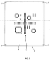
- Figures 1 to 6 illustrate a support system for supporting a printing screen unit 3 in a screen printing machine in accordance with a first embodiment of the present invention.
- the printing screen unit 3 comprises a printing screen 5, here rectangular in shape, which includes a pattern of printing apertures 6 which define the pattern of deposits to be printed, and attachment apertures 7 at the respective corners thereof to which attachment members 27 of a tensioning mechanism 18 are attached to provide for tensioning of the printing screen 5, as will be described in more detail hereinbelow.
- a pattern of printing apertures 6 is given only for the purposes of exemplification, and the pattern of printing apertures 6 could have any desired configuration.
- the pattern of printing apertures 6 can be formed, for example, by laser cutting or etching, as is well known in the art.
- the printing screen 5 comprises a sheet of a metal, such as stainless steel, or a plastic.
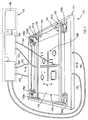
- the support system comprises a support assembly 15 in which the printing screen unit 3 is supported, and a control unit 16 for controlling the operation of the support assembly 15.
- the support assembly 15 comprises a support unit 17 in which the printing screen unit 3 is supported, and a tensioning mechanism 18 for tensioning the printing screen 5 of the printing screen unit 3.
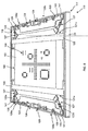
- the support unit 17 comprises a support frame 20, in this embodiment rectangular in shape, and first and second screen guiding units 21a, 21b which are disposed to one pair of opposite edges of the support frame 20 such as to define a pre-defined plane in which the printing screen 5 of the printing screen unit 3 is to be tensioned.
- the support assembly 15 is configured such that the screen guiding units 21a, 21b are disposed at positions corresponding to the respective ends of the printing screen unit 3 in the printing direction P.
- the support assembly 15 could be configured such that the screen guiding units 21a, 21b are disposed at positions corresponding to the respective sides of the printing screen unit 3 in the printing direction P.
- the support frame 20 includes referencing elements 22a, 22b at first and second adjacent corners thereof such as to allow for referencing of the position of the printing screen 5 of the printing screen unit 3, as will be described in more detail hereinbelow.
- the screen guiding units 21a, 21b each comprise a first, lower guide member 23, in this embodiment an elongate element having a downwardly and inwardly tapering upper surface at the inner edge thereof over which the printing screen 5 extends and a planar lower surface, and a second, upper guide member 24, in this embodiment an elongate roller rotatable about the longitudinal axis thereof, which is hinged such as to allow for fitting of the printing screen unit 3 in the support assembly 15 and, on fitting of the printing screen unit 3, is locked in juxtaposed relationship to the tapered, upper edge surface of the lower guide member 23 at such a height as to fix the lower surface of the printing screen 5 in the same plane as the lower surface of the lower guide member 23.
- the upper guide member 24 is hinged about pivots 25, 25 at the ends thereof.
- the screen guiding units 21a, 21b provide that the upper guide members 24 thereof can be locked at a varying height in dependence upon the thickness of the printing screen 5, thereby allowing for the use of printing screen units 3 having printing screens 5 of different thickness.
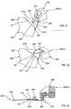
- the tensioning mechanism 18 comprises first to fourth tensioning units 26a-d for applying a tension to opposed corners of the printing screen 5 of the printing screen unit 3.
- the tensioning units 26a-d each comprise an attachment member 27 for attachment to a respective corner of the printing screen unit 3, an actuator 28, in this embodiment a pneumatic actuator, for generating a tensioning force, and a coupling assembly 29 for coupling the attachment member 27 and the actuator 28 such as to provide for tensioning of the attachment member 27 with the tensioning force.
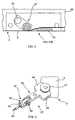
- the attachment member 27, in this embodiment a screw clamp comprises a first, clamp body 35 which is clamped to the respective corner of the printing screen unit 3 and includes a pivot 36 having an axis parallel to the plane of the printing screen 5, and a second, connector body 37 which is pivotally connected to the main clamp body 35 about the pivot 36 thereof and includes a pivot 39 having an axis orthogonal to the plane of the printing screen 5 to which the respective coupling assembly 29 is pivotally connected.
- the pivot 39 defines a referencing lug 40, which, where the attachment member 27 is of the first and second tensioning units 26a, 26b, provides for referencing of the attachment members 27 of the first and second tensioning units 26a, 26b to respective ones of the first and second referencing elements 22a, 22b of the support frame 20, as will be described in more detail hereinbelow.
- the coupling assembly 29 comprises a pulley 41 which is disposed at a respective corner of the support frame 20 and a cable 43 which is connected to the pivot 39 of the connector body 37 of the respective attachment member 27 and the respective actuator 28.
- the clamp body 35 comprises a first, upper clamping member 44 which is disposed to an upper surface of the printing screen 5, a second, lower clamping member 45 which is disposed to a lower surface of the printing screen 5, and a screw pin 47 which extends through the attachment aperture 7 in the respective corner of the printing screen 5 and is threadedly engaged with the upper and lower clamping members 44, 45 such as provide for clamping of the printing screen 5 therebetween.
- the control unit 16 comprises a tensioning unit actuator 49, in this embodiment a pneumatic supply, which is operable to operate the tensioning units 26a-d of the tensioning mechanism 18.
- the tensioning unit actuator 49 is connected to the actuator 28 of each of the respective tensioning units 26a-d, in this embodiment by respective pneumatic lines 53, such as to provide for actuation of the actuators 28 of the tensioning units 26a-d.
- the tensioning unit actuator 49 is configured such that the tensioning mechanism 18 applies a tension first to one, in this embodiment the first tensioning unit 26a such as to draw one corner of the printing screen unit 3 to a first reference position, as defined by the referencing lug 40 on the attachment member 27 of the first tensioning unit 26a abutting the first reference element 22a on the support frame 20, then a tension to the second tensioning unit 26b, which is adjacent the first tensioning unit 26a, such as to draw the adjacent corner of the printing screen unit 3 to a second reference position, as defined by the referencing lug 40 of the attachment member 27 of the second tensioning unit 26b abutting the second reference element 22b on the support frame 20, and subsequently to the pair of tensioning units 26c, 26d to the other, opposite side of the printing screen unit 3, thereby to achieve an even tension to the printing screen 5.
- the sequencing of the tensioning of the tensioning units 26a-d is provided by throttle valves, which act to throttle the rate of pressure increase to the actuators 28 of the tensioning
- the control unit 16 further comprises a controller 51 for controlling the tensioning unit actuator 49 in a screen printing operation.
- the support system provides for the application of differing tensions to the printing screen 5 of the printing screen unit 3.
- the controller 51 is configured to tension the printing screen 5 to one of a first, higher tension state during the printing phase such as to prevent lateral, in-plane movement of the printing screen 5, and a second, lower tension state during the separation phase in separating the printing screen 5 from a workpiece once printed.
- the present inventors have recognized that the application of different tensions to the printing screen 5 in the different phases of the screen printing operation, namely, the printing and separation phases, allows for the use of a high tension, such as currently used, during the printing phase in tensioning the printing screen 5 so as to fix the lateral, in-plane position of the printing screen 5, and yet advantageously allows for the application of a lower tension, in one embodiment no tension, of the printing screen 5 during the separation phase.
- the lower tensioning force enables the use of a lower separation force in separating the printing screen 5 from the workpiece.
- the use of a lower separation force is possible as the lower tensioning force provides for greater out-of plane deflection of the printing screen 5, which acts to promote the peeling action of the printing screen 5 in separating the printing screen 5 from a printed workpiece.
- a more regulated, progressive peeling action is achieved across the printing screen 5, with there being no high separation force acting to instantly separate the printing screen 5 from a printed workpiece, as would occur when such a high separation force exceeds the adhesive effect of the remaining printing medium in contact with both the printing screen 5 and the workpiece.
- the stresses caused by the out-of-plane deflection are so much lower than those created by the typical high tensioning force as not to cause any significant micro-displacement of the printing screen 5, and thereby provides for the printing of much improved deposits.
- the controller 51 acts to control the tensioning unit actuator 49 to tension the printing screen 5 to a first, high tension T 1 , as currently employed in existing tensioning systems, such as to fix the lateral, in-plane position of the printing screen 5.
- the printing head 61 comprises an elongate main body 62, and first and second wiper blades 63, 65, here elongate elements, which are attached to a lower surface of the main body 62.
- the wiper blades 63, 65 are inwardly and downwardly directed and define an outlet aperture 67 through which printing medium is delivered, and together with the main body 62 defines a chamber 69 which contains printing medium.
- the high tension T 1 as applied to the printing screen 5 acts to maintain the laterals in-plane position of the printing screen 5 during traversal of the printing head 61 thereover, with the printing head 61 acting to force printing medium into the printing apertures 6 in the printing screen 5.
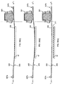
- the controller 51 acts to control the tensioning unit actuator 49 to tension the printing screen 5 to a second tension T 2 which is lower than the first, high tension T 1 as applied during the printing phase.
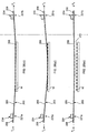
- the printing screen 5 is peeled away from the workpiece W in a controlled manner along advancing peeling fronts from opposite edges of the workpiece W to leave a pattern of printed deposits 71 having the same pattern as the pattern of printing apertures 6 in the printing screen 5.
- the screen guiding units 21a, 21b act to constrain the deflection of the printing screen 5 such that the deflection is uniform along the length of the advancing peeling fronts, thereby defining a flattened U-shape deflection profile.
- Figures 7 to 13 illustrate a support system for supporting a printing screen unit 103 in a screen printing operation in accordance with a second embodiment of the present invention.
- the printing screen unit 103 comprises a printing screen 105, here rectangular in shape, which includes a pattern of printing apertures 106 which define the pattern of deposits to be printed, attachment apertures 107 at the respective corners thereof to which attachment members 127 of a tensioning mechanism 118 are attached, as will be described in more detail hereinbelow, and first and second sets of clamping apertures 108a, 108b.
- the pattern of printing apertures 106 can be formed, for example, by laser cutting or etching, as is well known in the art.
- the attachment apertures 107 and the clamping apertures 108a, 108b can be formed, for example, by punching, laser cutting or etching, as is well known in the art.
- the printing screen 105 comprises a sheet of a metal, such as stainless steel, or a plastic.
- the support system comprises a support assembly 115 in which the printing screen unit 103 is supported, and a control unit 116 for controlling the operation of the support assembly 115.
- the support assembly 115 comprises a support unit 117 in which the printing screen unit 103 is supported, and a tensioning mechanism 118 for tensioning the printing screen 105 of the printing screen unit 103.
- the support unit 117 comprises a support frame 120, in this embodiment rectangular in shape, first and second screen clamping units 121a, 121b which are disposed to one pair of opposite edges of the support frame 120 and operable to clamp the printing screen 105, when tensioned, in a pre-defined plane, as will be described in more detail hereinbelow.
- the support assembly 115 is configured such that the screen clamping units 121a, 121b are disposed at positions corresponding to the respective ends of the printing screen unit 103 in the printing direction P.
- the support assembly 115 could be configured such that the screen clamping units 121a, 121b are disposed at positions corresponding to the respective sides of the printing screen unit 103 in the printing direction P.
- the support frame 120 includes referencing elements 122a, 122b at first and second adjacent corners thereof such as to allow for referencing of the position of the printing screen 105 of the printing screen unit 103, as will be described in more detail hereinbelow.
- the screen clamping units 121a, 121b each comprise a first, lower clamping member 123, in this embodiment an elongate member having a downwardly and inwardly tapering upper surface at the inner edge thereof over which the printing screen 105 extends and a planar lower surface, and a second, upper clamping member 124 which is operable such as to be clamped to the lower clamping member 123 and thereby clamp the printing screen 105 in a fixed lateral, in-plane position, with the lower surface of the printing screen 105 being in the same plane as the lower surface of the lower clamping member 123.
- the upper clamping member 124 comprises a hollow, elongate vacuum bar which includes vacuum apertures 125, here first and second slots, in the lower surface thereof which are configured such as to be in registration with a respective one of the sets of clamping apertures 108a, 108b in the printing screen 105, when tensioned.
- the upper clamping member 124 is clamped against the lower clamping member 123, thereby clamping the printing screen 105 therebetween by virtue of the applied vacuum acting on the upper surface of the lower clamping member 123 which is exposed at the respective set of clamping apertures 108a, 108b.
- the screen-clamping units 121a, 121b allow for the use of printing screens 105 of different thickness.
- the tensioning mechanism 118 comprises first to fourth tensioning units 126a-d for applying a tension to opposed corners of the printing screen 105.
- the tensioning units 126a-d each comprise an attachment member 127 for attachment to a respective corner of the printing screen unit 103, an actuator 128, in this embodiment a pneumatic actuator, for generating a tensioning force, and a coupling assembly 129 for coupling the attachment member 127 and the actuator 128 such as to provide for tensioning of the attachment member 127 with the tensioning force.
- the attachment member 127 in this embodiment a screw clamp, comprises a first, clamp body 135 which is clamped to the respective corner of the printing screen unit 103 and includes a pivot 136 having an axis parallel to the plane of the printing screen 105, and a second, connector body 137 which is pivotally connected to the clamp body 135 about the pivot 136 thereof and includes a pivot 139 having an axis orthogonal to the plane of the printing screen 105 to which the coupling assembly 129 is pivotally connected.
- the pivot 139 defines a referencing lug 140, which, where the attachment member 127 is of the first and second tensioning units 126a, 126b, provides for referencing of the attachment members 127 of the first and second tensioning units 126a, 126b to respective ones of the first and second referencing elements 122a, 122b of the support frame 120, as will be described in more detail hereinbelow.
- the coupling assembly 129 comprises a pulley 141 which is disposed at a respective corner of the support frame 120 and a cable 143 which is connected to the pivot 139 of the connector body 137 of the respective attachment member 127 and the respective actuator 128.
- the clamp body 135 comprises a first, upper clamping member 144 which is disposed to an upper surface of the printing screen 105, a second, lower clamping member 145 which is disposed to a lower surface of the printing screen 105, and a screw pin 147 which extends through the attachment aperture 107 in the respective corner of the printing screen 105 and is threadedly engaged with the upper and lower clamping members 144, 145 such as to provide for clamping of the printing screen 105 therebetween.
- the control unit 116 comprises a tensioning unit actuator 149, in this embodiment a pneumatic supply, which is operable to actuate the actuators 128 of the tensioning units 126a-d to apply predeterminable tensions to the printing screen 105 of the printing screen unit 103.
- the tensioning unit actuator 149 is connected to the actuator 128 of each of the respective tensioning units 126a-d, in this embodiment by respective pneumatic lines 153, such as to provide for actuation of the actuators 128 of the tensioning units 126a-d.
- the tensioning unit actuator 149 is configured such that the tensioning mechanism 118 applies a tension first to one, in this embodiment the first tensioning unit 126a such as to draw one corner of the printing screen unit 103 to a first reference position, as defined by the referencing lug 140 on the attachment member 127 of the first tensioning unit 126a abutting the first reference element 122a on the support frame 120, then a tension to the second tensioning unit 126b, which is adjacent the first tensioning unit 126a, such as to draw the adjacent corner of the printing screen unit 103 to a second reference position, as defined by the referencing lug 140 of the attachment member 127 of the second tensioning unit 126b abutting the second reference element 122b on the support frame 120, and subsequently to the pair of tensioning units 126c, 126d to the other, opposite side of the printing screen unit 103, thereby to achieve an even tension to the printing screen 105.
- the sequencing of the tensioning of the tensioning units 126a-d is provided by
- the control unit 116 further comprises a clamping unit actuator 155, in this embodiment a vacuum supply, which is operable to actuate the screen clamping units 121a, 121b to clamp the printing screen 105 in a fixed lateral position.
- the clamping unit actuator 155 is connected to each of the screen clamping units 121a, 121b, in this embodiment by respective vacuum lines 157, such as to provide for actuation of the screen clamping units 121a, 121b.
- the control unit 116 further comprises a controller 159 for controlling the tensioning unit actuator 149 and-the-clamping unit actuator 155 in a screen printing operation.
- the support system enables the application of differing tensions to the printing screen 105 in a screen printing operation, and also provides for the clamping of the printing screen 105 in a fixed lateral, in-plane position during the printing phase.
- the controller 159 is configured, in the printing phase in printing a workpiece, to control the tensioning unit actuator 149 to actuate the tensioning units 126a-d to tension the printing screen 105 to a first, high tension state and the clamping unit actuator 155 to actuate the screen clamping units 121a, 121b to clamp the printing screen 105 such as to prevent lateral, in-plane movement of the printing screen 105, and, in the separation phase in separating the printing screen 105 from a workpiece once printed, to control the tensioning unit actuator 149 to actuate the tensioning units 126a-d to tension the printing screen 105 to a second, lower tension state and, here subsequently, the clamping unit actuator 155 to de-actuate the screen clamping units 121a, 121b to release the printing screen 105 from the clamped state.
- the present inventors have recognized that the application of different tensions to the printing screen 105 in different phases of the screen printing operation, namely, the printing and separation phases, allows for the use of a high tension, such as currently used, during the printing phase in tensioning the printing screen 105 so as to fix the lateral, in-plane position of the printing screen 105, and yet advantageously allows for tensioning of the printing screen 105 to a lower tension in the separation phase.
- the lower tensioning force enables the use of a lower separation force in separating the printing screen 105 from the workpiece.
- the use of a lower separation force is possible as the lower tensioning force provides for greater out-of plane deflection of the printing screen 105, which acts to promote the peeling action of the printing screen 105 in separating the printing screen 105 from a printed workpiece.
- a more regulated, progressive peeling action is achieved across the printing screen 105, with there being no high separation force acting to instantly separate the printing screen 105 from a printed workpiece as would occur when such a high separation force exceeds the adhesive effect of the remaining printing medium in contact with both the printing screen 105 and the workpiece.
- the stresses caused by the out-of-plane deflection of the printing screen 105 are so much lower than those created by the typical high tensioning force as not to cause any significant micro-displacement of the printing screen 105, and thereby provides for the printing of much improved deposits.
- the present inventors have also recognized that, through clamping the printing screen 105 so as to prevent lateral, in-plane movement thereof during the printing phase, the tensioning force applied to the printing screen 105 during the printing phase can be reduced from that currently used in existing tensioning systems. Also, by maintaining the printing screen 105 in the clamped state when altering the tension thereof as applied by the tensioning units 126a-d, the tensioning force as applied by each of the tensioning units 126a-d can be allowed to equilibriate, thereby avoiding the possibility of different tensioning forces being applied by different ones of the tensioning units 126a-d, which could possibly lead to displacement of the printing screen 105.
- the controller 159 is configured to control the tensioning unit actuator 149 to actuate the tensioning units 126a-d to tension the printing screen 105 to one tension state during the screen printing operation, that is, both the printing and separation phases, and the clamping unit actuator 155 to actuate the screen clamping units 121a, 121b to clamp the printing screen 105 during the printing phase such as to prevent lateral movement of the printing screen and de-actuate the screen clamping units 121a, 121b prior to the separation phase to release the printing screen 105 from the clamped state.
- the present inventors have recognized that, through clamping the printing screen 105 so as to prevent lateral movement thereof during the printing phase, the tensioning force applied to the printing screen 105 during the printing phase can be reduced from the high tension as currently used in existing tensioning systems.
- the tensioning force applied to printing screen 105 during the printing phase need only be sufficient to render the printing screen 105 in the planar configuration as required for printing, and need not approach the high tensioning force employed by the current tensioning systems to fix the lateral, in-plane position of the printing screen 105 during printing.
- the printing head 161 comprises an elongate main body 162, and first and second wiper blades 163, 165, here elongate elements, which are attached to a lower surface of the main body 162.
- the wiper blades 163, 165 are inwardly and downwardly directed and define an outlet aperture 167 through which printing medium is delivered, and together with the main body 162 define a chamber 169 which contains printing medium.
- the controller 159 acts to control the tensioning unit actuator 149 to actuate the tensioning units 126a-d to tension the printing screen 105 to a first tension T 1 , where the first tension T 1 is such as at least to render the printing screen 105 in a planar configuration, and the clamping unit actuator 155 to actuate the screen clamping units 121a, 121b to clamp the printing screen 105 and thereby fix the lateral, in-plane position thereof.
- the screen clamping units 121a, 121b act to maintain the lateral, in-plane position of the printing screen 105 during traversal of the printing head 161 thereover, with the printing head 161 acting to force printing medium into the printing apertures 106 in the printing screen 105.
- the controller 159 acts to control the tensioning unit actuator 149 to actuate the tensioning units 126a-d to tension the printing screen 105 to a second tension T 2 which is lower than the first tension T 1 as applied during the printing phase, and the clamping unit actuator 155 to de-actuate the screen clamping units 121a, 121b, and thereby release the printing screen 105 from the clamped state.
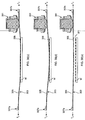
- the printing screen 105 is peeled away from the workpiece W in a controlled manner along advancing peeling fronts from opposite edges of the workpiece W to leave a pattern of printed deposits 171 having the same pattern as the pattern of printing apertures 106 in the printing screen 105.
- the screen clamping units 121a, 121b act to constrain the deflection of the printing screen 105 such that the deflection is uniform along the length of the advancing peeling fronts, thereby defining a flattened U-shape deflection profile.
- a more controlled peel is achieved as compared to arrangements where the peeling occurs along more than one axis and causes a "concave" deflection of the printing screen 105.
- the peeling effect in peeling the printing screen 105 from the workpiece W is promoted and provides for improved separation of the workpiece W from the printing screen 105, thereby providing printed deposits 171 of improved quality.
- the controller 159 acts to control the tensioning unit actuator 149 to actuate the tensioning units 126a-d to tension the printing screen 105 to a predeterminable tension T 1 , where the tension T 1 is such as at least to render the printing screen 105 in a planar configuration, and the clamping unit actuator 155 to actuate the screen clamping units 121a, 121b to clamp the printing screen 105 and thereby fix the lateral, in-plane position thereof.
- the screen clamping units 121a, 121b act to maintain the lateral, in-plane position of the printing screen 105 during traversal of the printing head 161 thereover, with the printing head 161 acting to force printing medium into the printing apertures 106 in the printing screen 105.
- the controller 159 acts to control the clamping unit actuator 155 to de-actuate the screen clamping units 121a, 121b, and thereby release the printing screen 105 from the clamped state.
- the printing screen 105 is peeled away from the workpiece W in a controlled manner along advancing peeling fronts from opposite edges of the workpiece W to leave a pattern of printed deposits 171 having the same pattern as the pattern of printing apertures 106 in the printing screen 105.
- the screen clamping units 121a, 121b act to constrain the deflection of the printing screen 105 such that the deflection is uniform along the length of the advancing peeling fronts, thereby defining a flattened U-shape deflection profile.
- a more controlled peel is achieved as compared to arrangements where the peeling occurs along more than one axis and causes a "concave" deflection of the printing screen 105.
- the screen clamping units 121a, 121b could comprise only one, upper clamping member 124 and the printing screen unit 103 modified such as to omit the sets of clamping apertures 108a, 108b from the printing screen 105.
- the printing screen 105 is clamped to the upper clamping members 124 of the screen clamping units 121a, 121b by the action of the vacuum on the exposed surfaces of the printing screen 105 at the vacuum apertures 125 in the respective upper clamping members 124, with the height of the printing screen 105 being fixed in a pre-defined plane by the planar lower surface of the upper clamping members 124.
- the clamping unit actuator 155 can be configured such as to apply a first vacuum to the upper clamping members 124 during the printing phase such as to clamp the printing screen 105 in a fixed lateral, in-plane position, and a second, lower vacuum to the upper clamping members 124 during the separation phase which is such as to allow for lateral movement of the printing screen 105 relative to the upper clamping members 124 and yet provide for the printing screen 105 at least initially to be drawn towards the respective upper clamping members 124 such as to allow for transmission of the separation force thereat.
- the screen clamping units 121a, 121b could comprise only one clamping member 124, where comprising the above-described upper clamping member 124 in an inverted orient, which is disposed to a lower surface of the printing screen 105, and the printing screen unit 103 modified such as to omit the sets of clamping apertures 108a, 108b from the printing screen 105.
- the printing screen 105 is clamped to the clamping members 124 of the screen clamping units 121a, 121b by the action of the vacuum on the exposed surfaces of the printing screen 105 at the vacuum apertures 125 in the clamping members 124, with the height of the printing screen 105 being fixed in a pre-defined plane as defined by the planar upper surface of the clamping members 124.
- Figures 16 to 18 illustrate a support system for supporting a printing screen unit 103 in a screen printing operation in accordance with a third embodiment of the present invention.
- the support system is very similar to the support system of the above-described second embodiment, and thus, in order to avoid unnecessary duplication of description, only the differences will be described in detail.
- the support system of this embodiment differs from that of the second-described embodiment in that the screen clamping units 121a, 121b are movable relative to one another in a vertical orient.
- first screen clamping unit 121a is mounted to the support frame 120 by lifting jacks 173, in this embodiment pneumatically-operated, at the respective ends thereof, which provide for the first screen clamping unit 121a to be raised relative to the second screen clamping unit 121b in the separation phase, as will be described in more detail hereinbelow.
- the control unit 116 further comprises a lifting jack actuator 175 which is operably connected to the controller 159 and is operable to actuate the lifting jacks 173 to raise the first screen clamping unit 121a relative to the second screen clamping unit 121b.
- the jack actuator 175 is connected to the lifting jacks 173, in this embodiment by respective pneumatic lines 177, such as to provide for actuation of the lifting jacks 173.
- the controller 159 is configured, in the printing phase, to control the tensioning unit actuator 149 to actuate the tensioning units 126a-d to tension the printing screen 105 to a first tension and the clamping unit actuator 155 to actuate the screen clamping units 121a, 121b to clamp the printing screen 105 such as to prevent lateral, in-plane movement of the printing screen 105, and, in the separation phase, to control the tensioning unit actuator 149 to actuate the tensioning units 126a-d to tension the printing screen 105 to a second tension lower than the first tension, the clamping unit actuator 155 to de-actuate the first clamping unit 121a to release the printing screen 105 from the clamped state thereat and the jack actuator 175 to raise the first screen clamping unit 121a to separate the printing screen 105 from a workpiece once printed.
- the present inventors have recognized that the application of different tensions to the printing screen 105 in different phases of the screen printing operation, namely, the printing and separation phases, allows for the use of a high tension, such as currently used, during the printing phase in tensioning the printing screen 105 so as to fix the lateral, in-plane position of the printing screen 105, and yet advantageously allows for tensioning of the printing screen 105 to a lower tension in the separation phase.
- the lower tensioning force enables the use of a lower separation force, as achieved by raising the first screen clamping unit 121a relative to the second screen clamping unit 121b in separating the printing screen 105 from a workpiece, which acts to promote the peeling action of the printing screen 105 in separating the printing screen 105 from a printed workpiece.
- a more regulated, progressive peeling action is achieved across the printing screen 105, with there being no high separation force acting to instantly separate the printing screen 105 from a printed workpiece as would occur when such a high separation force exceeds the adhesive effect of the remaining printing medium in contact with both the printing screen 105 and the workpiece.
- the stresses caused by the out-of-plane deflection of the printing screen 105 are so much lower than those created by the typical high tensioning force as not to cause any significant micro-displacement of the printing screen 105, and thereby provides for the printing of much improved deposits.
- the present inventors have also recognized that, through clamping the printing screen 105 so as to prevent lateral, in-plane movement thereof during the printing phase, the tensioning force applied to the printing screen 105 during the printing phase can be reduced from that currently used in existing tensioning systems. Also, by maintaining the printing screen 105 in the clamped state when altering the tension thereof as applied by the tensioning units 126a-d, the tensioning force as applied by each of the tensioning units 126a-d can be allowed to equilibriate, thereby avoiding the possibility of different tensioning forces being applied by different ones of the tensioning units 126a-d, which could possibly lead to displacement of the printing screen 105.
- the controller 159 is configured to control the tensioning unit actuator 149 to actuate the tensioning units 126a-d to tension the printing screen 105 to one predeterminable tension during the entire screen printing operation, that is, both the printing and separation phases, the clamping unit actuator 155 to actuate the screen clamping units 121a, 121b to clamp the printing screen 105 in the printing phase such as to prevent lateral, in-plane movement of the printing screen 105 and de-actuate the first screen clamping unit 121a prior to the separation phase such as to allow for separation of the printing screen 105 from the workpiece by raising the first screen clamping unit 121a relative to the second screen clamping unit 121b, and the lifting jack actuator 175 to actuate the lifting jacks 173 to raise the first screen clamping unit 121a relative to the second screen clamping unit 121b.
- the present inventors have recognized that, through clamping the printing screen 105 so as to prevent lateral, in-plane movement thereof during the printing phase, the tensioning force applied to printing screen 105 during the printing phase can be reduced from the high tensioning force as currently used in existing tensioning systems.
- the tensioning force applied to the printing screen 105 during the printing phase need only be sufficient to render the printing screen 105 in the planar configuration as required for printing, and need not approach the high tensioning force employed by the current tensioning systems to fix the lateral, in-plane position of the printing screen 105 during the printing phase.
- the lower tensioning force enables the use of a lower separation force, as achieved by raising the first screen clamping unit 121a relative to the second screen clamping unit 121b in separating the printing screen 105 from the workpiece, which acts to promote the peeling action of the printing screen 105 in separating the printing screen 105 from a printed workpiece.
- a more regulated, progressive peeling action is achieved across the printing screen 105, with there being no high separation force acting to instantly separate the printing screen 105 from a printed workpiece as would occur when such a high separation force exceeds the adhesive effect of the remaining printing medium in contact with both the printing screen 105 and the workpiece.
- the stresses caused by the out-of-plane deflection of the printing screen 105 are so much lower than those created by the typical high tensioning force as not to cause any significant micro-displacement of the printing screen 105, and thereby provides for the printing of much improved deposits.
- the other edge of the printing screen 105 remains stationary and can thus accommodate a printing head 161 following a screen printing operation.
- the controller 159 acts to control the tensioning unit actuator 149 to actuate the tensioning units 126a-d to tension the printing screen 105 to a first tension T 1 , where the first tension T 1 is such as at least to render the printing screen 105 in a planar configuration, and the clamping unit actuator 155 to actuate the screen clamping units 121a, 121b to clamp the printing screen 105 and thereby fix the lateral, in-plane position thereof.
- the screen clamping units 121a, 121b act to fix the lateral, in-plane position of the printing screen 105 during traversal of the printing head 161 thereover, with the printing head 161 acting to force printing medium into the printing apertures 106 in the printing screen 105.
- the controller 159 acts first to control the tensioning unit actuator 149 to actuate the tensioning units 126a-d to tension the printing screen 105 to a second tension T 2 which is lower than the first tension T 1 as applied during the printing phase, subsequently to control the clamping unit actuator 155 to de-actuate the first screen clamping unit 121a and thereby release the printing screen 105 from the clamped state thereat, and then control the lifting jack actuator 175 to actuate the lifting jacks 173 to raise the first screen clamping unit 121a to separate the printing screen 105 from the workpiece W.
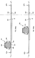
- the printing screen 105 is peeled away from the workpiece W in a controlled manner along an advancing peeling front from one edge of the workpiece W adjacent the first screen clamping unit 121a to leave a pattern of printed deposits 171 having the same pattern as the pattern of printing apertures 106 in the printing screen 105.
- the screen clamping units 121a, 121b act to constrain the deflection of the printing screen as such that the deflection is uniform along the length of the advancing peeling front, thereby defining a flattened and skewed U-shape deflection profile by constraining the axis of peeling, a more controlled peel is achieved as compared to arrangements where the peeling occurs along more than one axis and causes a "conclave" deflection of the printing screen 105.
- the peeling effect in peeling the printing screen 105 from the workpiece W is promoted and provides for improved separation of the workpiece W from the printing screen 105, thereby providing printed deposits 171 of improved quality.
- the controller 159 acts to control the tensioning unit actuator 149 to actuate the tensioning units 126a-d to tension the printing screen 105 to a predeterminable tension T 1 , where the tension T 1 is such as at least to render the printing screen 105 in a planar configuration, and the clamping unit actuator 155 to actuate the screen clamping units 121a, 121b to clamp the printing screen 105 and thereby fix the lateral, in-plane position thereof.
- the screen clamping units 121a, 121b act to maintain the lateral, in-plane position of the printing screen 105 during traversal of the printing head 161 thereover, with the printing head 161 acting to force printing medium into the printing apertures 106 in the printing screen 105.
- the controller 159 acts to control the clamping unit actuator 155 to de-actuate the first screen clamping unit 121a and thereby release the printing screen 105 from the clamped state thereat, and then control the jack actuator 175 to actuate the lifting jacks 173 to raise the first screen clamping unit 121a relative to the second screen clamping unit 121b and separate the printing screen 105 from the workpiece W.
- the printing screen 105 is peeled away from the workpiece W in a controlled manner along an advancing peeling front from one edge of the workpiece W to leave a pattern of printed deposits 171 having the same pattern as the pattern of printing apertures 106 in the printing screen 105.
- the screen clamping units 121a, 121b act to constrain the deflection of the printing screen 105 such that the deflection is uniform along the length of the advancing peeling front, thereby defining a flattened and skewed U-shape deflection profile.
- a more controlled peel is achieved as compared to arrangements where the peeling occurs along more than one axis and causes a "concave" deflection of the printing screen 105.
- the second screen clamping unit 121b could instead be configured to include lifting jacks 173 to provide for the second screen clamping unit 121b to be raised relative to the first screen clamping unit 121a where fixed to the support frame 120.
- both the first and second screen clamping units 121a, 121b could include lifting jacks 173 to provide for one of the screen clamping units 121a, 121b to be raised relative to the other of the screen clamping units 121a, 121b.
- the other of the screen clamping units 121a, 121b can be maintained at a fixed position while raising the one of the screen clamping units 121a, 121b.
- both the one and other of the screen clamping units 121a, 121b could be raised, where the one of the screen clamping units 121a, 121b is raised at a rate greater than the other of the screen clamping units 121a, 121b.
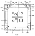
- Figures 19 to 27 illustrate a support system for supporting a printing screen unit 203 in a screen printing operation in accordance with a fourth embodiment of the present invention.
- the printing screen unit 203 comprises a printing screen 205, here rectangular in shape, which includes a pattern of printing apertures 206 which define the pattern of deposits to be printed, attachment members 207 at the respective corners thereof to which attachment members 227 of a tensioning mechanism 218 are attached, as will be described in more detail hereinbelow and support elements 208, which are attached to one pair of opposite edges of the printing screen 205 to constrain deflection thereof, as will be described in more detail hereinbelow.
- the pattern of printing apertures 206 can be formed, for example, by laser cutting or etching, as is well known in the art.
- the printing screen 205 comprises a sheet of a metal, such as stainless steel, or a respective plastic.
- the attachment members 207 each comprise a re-inforcing element 209 for re-inforcing the respective corner of the printing screen 205, and a connector element 210 to which a tensioning unit 226a-d is connected, as will be described in more detail hereinbelow.
- the reinforcing element 209 comprises a plate 211 which is attached, here bonded, to the upper surface of the printing screen 205 and includes first and second referencing surfaces 211a, 211b which provide for referencing of the position of the printing screen unit 203, as will be described in more detail hereinbelow.
- the connector element 210 comprises an elongate rod 212 which extends along an axis extending through the center of the printing screen 205 and includes an enlarged head 213 which defines an engagement surface 214, in this embodiment a part-spherical surface.
- the support elements 208 comprise elongate strips which extend along one pair of opposite edges of the printing screen 205, here the lateral edges of the printing screen 205 in the printing direction P.
- the support elements 208 act to constrain the deflection such that the deflection is uniform along the length of the advancing peeling fronts, thereby defining a flattened U-shape deflection profile.
- the support elements 208 are configured to transmit in-plane tensioning forces, but resist axial bending thereof.
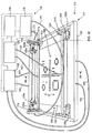
- the support system comprises a support assembly 215 in which the printing screen unit 203 is supported, and a control unit 216 for controlling the operation of the support assembly 215.
- the support assembly 215 comprises a support unit 217 in which the printing screen unit 203 is supported, and a tensioning mechanism 218 for tensioning the printing screen 205 of the printing screen unit 203.
- the support unit 217 comprises a support frame 220, in this embodiment rectangular in shape, and first and second screen clamping units 221a, 221b which are disposed to one pair of opposite edges of the support frame 220 and operable to clamp the printing screen 205, when tensioned, in a pre-defined plane, as will be described in more detail hereinbelow.
- the support assembly 215 is configured such that the screen clamping units 221a, 221b are disposed at positions corresponding to the respective sides of the printing screen unit 203 in the printing direction P.
- the support assembly 215 could be configured such that the screen clamping units 221a, 221b are disposed at positions corresponding to the respective ends of the printing screen unit 203 in the printing direction P.
- the support frame 220 includes first and second referencing elements 222, 223 at respective ones of first and second adjacent corners thereof such as to allow for referencing of the position of the printing screen 205 of the printing screen unit 203, as will be described in more detail hereinbelow.
- the first referencing element 222 comprises first and second projections 222a, 222b which each define a reference position and are configured to engage respective ones of the reference surfaces 211a, 211b of the respective attachment member 207 in referencing the position of the same
- the second referencing element 223 comprises a projection 223a which defines a reference position and is configured to engage one of the reference surfaces 211a, 211b, here the first reference surface 211a, of the attachment member 207 at the adjacent corner of the support frame 220.
- the screen clamping units 221a, 221b each comprise a screen clamping member 224, in this embodiment an elongate member having a planar lower surface which is operable to clamp the printing screen 205 in a fixed lateral, in-plane position, with the lower surface of the printing screen 205 being in the same plane as the lower edge of the support fame 220.
- the screen clamping member 224 comprises a hollow, elongate vacuum bar which includes vacuum apertures 225, here a plurality of elongate slots, in the lower surface thereof.
- the screen clamping members 224 On applying a vacuum to the screen clamping members 224, the screen clamping members 224 are clamped against the printing screen 205 by virtue of the applied vacuum acting on the surface of the printing screen 205 which is exposed at the vacuum apertures 225 in the respective screen clamping members 224.
- the tensioning mechanism 218 comprises first to fourth tensioning units 226a-d for applying a tensioning force to opposed corners of the printing screen 205.
- the tensioning units 226a-d each comprise an attachment member 227 which is attached to a respective one of the attachment members 207 of the printing screen unit 203, and an actuator 228, in this embodiment a pneumatic actuator, for generating a tensioning force which is connected to the attachment member 227, here fixedly, and a respective one of the corners of the support frame 220 about a pivot 230 to provide for tensioning of the respective attachment member 207 of the printing screen unit 203, and hence the printing screen 205, with the tensioning force.
- an actuator 228, in this embodiment a pneumatic actuator for generating a tensioning force which is connected to the attachment member 227, here fixedly, and a respective one of the corners of the support frame 220 about a pivot 230 to provide for tensioning of the respective attachment member 207 of the printing screen unit 203, and hence the printing screen 205, with the tensioning force.
- the attachment member 227 comprises a body 235 which includes a recess 236 for receiving the head 213 of the connector element 210 of a respective one of the attachment members 207 of the printing screen unit 203 and a slot 237 at the outer, forward edge thereof for receiving the elongate rod 212 of the connector element 210 of the respective attachment member 207.
- the recess 236 includes an engagement surface 238, here a part-cylindrical surface, at a forward, outer edge thereof which engages with the engagement surface 214, also here part-spherical, of the enlarged head 213 of the connector element 210 of the respective attachment member 207.
- each of the attachment members 207 of the printing screen unit 203 is pivotable relative to the respective attachment members 227 about axes parallel to the plane of the printing screen 205 such as to allow for free pivoting movement of the attachment members 207, and hence unrestrained deflection of the printing screen 205 when a central region of the printing screen 205 is deflected downwardly, as will be described in more detail hereinbelow.
- the control unit 216 comprises a tensioning unit actuator 249, in this embodiment a pneumatic supply, which is operable to actuate the actuators 228 of the tensioning units 226a-d to apply predeterminable tensions to the printing screen 205 of the printing screen unit 203.
- the tensioning unit actuator 249 is connected to the actuator 228 of each of the respective tensioning units 226a-d, in this embodiment by respective pneumatic lines 253, such as to provide for actuation of the actuators 228 of the tensioning units 226a-d.
- the tensioning unit actuator 249 is configured such that the tensioning mechanism 218 applies a tensioning force first to one, in this embodiment the first tensioning unit 226a such as to draw one corner of the printing screen unit 203 to a first reference position, as defined by the reference surfaces 211a, 211b of the attachment member 207 at the one corner of the printing screen unit 203 abutting the reference projections 222a, 222b at the one corner of the support frame 220, then a tensioning force to a second tensioning unit 226b which is adjacent the first tensioning unit 226a such as to draw the adjacent corner of the printing screen unit 203 to a second reference position, as defined by the one reference surface 211a of the adjacent attachment member 207 abutting the reference projection 223a at the adjacent corner of the support frame 220, and subsequently to the pair of tensioning units 226c, 226d to the other side of the printing screen unit 203, thereby to achieve an even tension to the printing screen 205.
- the sequencing of the tensioning applies a
- the control unit 216 further comprises a clamping unit actuator 255, in this embodiment a vacuum supply, which is operable to actuate the screen clamping units 221a, 221b to clamp the printing screen 205 in a fixed lateral, in-plane position.
- the clamping unit actuator 255 is connected to the screen clamping units 221a, 221b, in this embodiment by respective vacuum lines 257, such as to provide for actuation of the screen clamping units 221a, 221b.
- the control unit 216 further comprises a controller 259 for controlling the tensioning unit actuator 249 and the clamping unit actuator 255 in a screen printing operation.
- the support system enables for the application of differing tensions to the printing screen 205 of the printing screen unit 203.
- the controller 259 is configured to control the tensioning unit actuator 249 to actuate the tensioning units 226a-d to tension the printing screen 205 to one tension during the entire screen printing operation, that is, both the printing and separation phases, and the clamping unit actuator 255 to actuate the screen clamping units 221a, 221b to clamp the printing screen 205 during the printing phase such as to prevent lateral, in-plane movement of the printing screen 205 and de-actuate the screen clamping units 221a, 221b prior to the separation phase such as to release the printing screen 205 from the clamped state.
- the controller 259 is configured to tension the printing screen 205 to a first, high tension during the printing phase such as to prevent lateral, in-plane movement of the printing screen 205, and a second, lower tension during the separation phase in separating the printing screen 205 from a workpiece once printed, and the clamping unit actuator 255 to actuate the screen clamping units 221a, 221b to clamp the printing screen 205 during the printing phase such as to prevent lateral, in-plane movement of the printing screen 205 and de-actuate the screen clamping units 221a, 221b prior to the separation phase such as to release the printing screen 205 from the clamped state.
- the present inventors have recognized that, through clamping the printing screen 205 so as to prevent lateral, in-plane movement thereof during the printing phase, the tensioning force applied to printing screen 205 during the printing phase can be reduced from the high tension currently used in existing tensioning systems.
- the tensioning force applied to the printing screen 205 during the printing phase need only be sufficient to render the printing screen 205 in the planar configuration as required for printing, and need not approach the high tensioning force employed by the current tensioning systems to fix the lateral, in-plane position of the printing screen 205.
- the lower tensioning force In tensioning the printing screen 205 to a lower tension, the lower tensioning force enables the use of a lower separation force in separating the printing screen 205 from the workpiece.
- the use of a lower separation force is possible as the lower tensioning force provides for greater out-of plane deflection of the printing screen 205, which acts to promote the peeling action of the printing screen 205 in separating the printing screen 205 from a printed workpiece.
- the printing head 261 comprises an elongate main body 262, and first and second wiper blades 263, 265, here elongate elements, which are attached to a lower surface of the main body 262.
- the wiper blades 263, 265 are inwardly and downwardly directed and define an outlet aperture 267 through which printing material is delivered, and together with the main body 262 define a chamber 269 which contains printing medium.
- the controller 259 acts to control the tensioning unit actuator 249 to actuate the tensioning units 226a-d to tension the printing screen 205 to a first tension T 1 , where the first tension T 1 is such as at least to render the printing screen 205 in a planar configuration, and the clamping unit actuator 255 to actuate the screen clamping units 221a, 221b to clamp the printing screen 205 and thereby fix the lateral, in-plane position thereof.
- the screen clamping units 221a, 221b act to maintain the lateral, in-plane position of the printing screen 205 during traversal of the printing head 261 thereover, with the printing head 261 acting to force printing medium into the printing apertures 206 in the printing screen 205.
- the controller 259 acts to control the tensioning unit actuator 249 to actuate the tensioning units 226a-d to tension the printing screen 205 to a second tension T 2 which is lower than the first tension T 1 as applied during the printing phase, and the clamping unit actuator 255 to de-actuate the screen clamping units 221a, 221b, and thereby release the printing screen 205 from the clamped state.
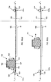
- the printing screen 205 is peeled away from the workpiece W in a controlled manner along advancing peeling fronts from opposite edges of the workpiece W to leave a pattern of printed deposits 271 having the same pattern as the pattern of printing apertures 206 in the printing screen 205.
- the peeling effect in peeling the printing screen 205 from the workpiece W is promoted and provides for improved separation of the workpiece W from the printing screen 205, thereby providing printed deposits 271 of improved quality.
- the workpiece W is separated from the printing screen unit 203, and the screen printing operation can be repeated in printing another workpiece W.
- the controller 259 acts to control the tensioning unit actuator 249 to actuate the tensioning units 226a-d to tension the printing screen 205 to a predeterminable tension T 1 , where the tension T 1 is such as at least to render the printing screen 205 in a planar configuration, and the clamping unit actuator 255 to actuate the screen clamping units 221a, 221b to clamp the printing screen 205 and thereby fix the lateral, in-plane position thereof.
- the screen clamping units 221a, 221b act to maintain the lateral, in-plane position of the printing screen 205 during traversal of the printing head 261 thereover, with the printing head 261 acting to force printing medium into the printing apertures 206 in the printing screen 205.
- the controller 259 acts to control the clamping unit actuator 255 to de-actuate the screen clamping units 221a, 221b, and thereby release the printing screen 205 from the clamped state.
- the printing screen 205 is peeled away from the workpiece W in a controlled manner along advancing peeling fronts from opposite edges of the workpiece W to leave a pattern of printed deposits 271 having the same pattern as the pattern of printing apertures 206 in the printing screen 205.
- the peeling effect in peeling the printing screen 205 from the workpiece W is promoted and provides for improved separation of the workpiece W from the printing screen 205, thereby providing printed deposits 271 of improved quality.
- the workpiece W is separated from the printing screen unit 203, and the screen printing operation can be repeated in printing another workpiece W.
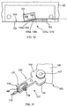
- Figures 28 to 30 illustrate one modified connection for the attachment members 207 of the printing screen unit 203 and the attachment members 227 of the tensioning units 226a-d of the support assembly 215 for the support system of Figure 19 .
- the attachment members 207 each similarly comprise a re-inforcing element 209 for re-inforcing the respective corner of the printing screen 205, and a connector element 210 to which a tensioning unit 226a-d is connected.
- the re-inforcing element 209 again similarly comprises a plate 211 which is attached, here bonded, to the upper surface of the printing screen 205 and includes first and second referencing surfaces 211a, 211b which provide for the referencing of the position of the printing screen unit 203.
- the connector element 210 comprises an arcuate, hook element 273, here formed from a rolled sheet, which defines a recess 275 for receiving the attachment member 227 of the respective tensioning unit 226a-d which defines an engagement surface 277, here a part-cylindrical surface, which is disposed in the plane of the printing screen 205 and extends orthogonally to a tensioning axis extending from the respective corner of the printing screen 205 and through the center of the printing screen 205, and includes a slot 278 located on the tensioning axis for receiving the respective attachment member 227.
- each tensioning unit 226a-d comprises an elongate rod 279 which extends along the tensioning axis and includes an enlarged head 281 which defines an engagement surface 283, in this embodiment a part-spherical surface, which engages the engagement surface 277 of the recess 275 in the hook element 273 of the connector element 210.
- each of the attachment members 207 of the printing screen 203 is pivotable relative to the respective attachment members 227 of the tensioning units 226a-d about axes parallel to the plane of the printing screen 205 such as to allow for free pivoting movement of the attachment members 207, and hence unrestrained deflection of the printing screen 205 when a central region of the printing screen 205 is deflected downwardly.
- Figures 31 to 33 illustrate another modified connection for the attachment members 207 of the printing screen unit 203 and the attachment members 227 of the tensioning units 226a-d of the support assembly 215 for the support system of Figure 19 .
- the attachment members 207 of the printing screen unit 203 each comprise a re-inforcing element 209 for re-inforcing the respective corner of the printing screen 205 which includes a connector aperture 284, here of key hole shape, to which the attachment member 227 of a respective one of the tensioning units 226a-d is connected.
- the re-inforcing element 209 comprises first and second plates 211', 211" between which the printing screen 205 is attached, here bonded, and define first and second referencing surfaces 211a, 211b which provide for the referencing of the position of the printing screen unit 203.
- the attachment member 227 comprises a body 285 which includes an upstanding lug 287 for engagement in the connector aperture 284 in the re-inforcing element 209 of the respective attachment member 207.
- the lug 287 extends along an axis orthogonal to the plane of the printing screen 205 and includes an enlarged head for captively retaining the respective attachment member 207 thereon.
- the attachment members 227 of the respective tensioning units 226a-d provide for some pivoting movement of the respective attachment members 207 of the printing screen unit 203 thereto, and hence accommodate deflection of the printing screen 205 when a central region of the printing screen 205 is deflected downwardly in the separation phase in separating the printing screen 205 from a workpiece.
- Figures 34 to 39 illustrate a support system for supporting a printing screen unit 303 in a screen printing operation in accordance with a fifth embodiment of the present invention.
- the printing screen unit 303 comprises a printing screen 305, here rectangular in shape, which includes a pattern of printing apertures 306 which define the pattern of deposits to be printed, and first and second attachment members 307a, 307b, here elongate elements, attached to one pair of opposite edges of the printing screen 305 to which attachment members 327 of a tensioning mechanism 318 are attached, as will be described in more detail hereinbelow.
- first and second attachment members 307a, 307b here elongate elements, attached to one pair of opposite edges of the printing screen 305 to which attachment members 327 of a tensioning mechanism 318 are attached, as will be described in more detail hereinbelow.
- the pattern of printing apertures 306 can be formed, for example, by laser cutting or etching, as is well known in the art.
- the printing screen 305 comprises a sheet of a metal, such as stainless steel, or a plastic.
- the support system comprises a support assembly 315 in which the printing screen unit 303 is supported, and a control unit 316 for controlling the operation of the support assembly 315.
- the support assembly 315 comprises a support unit 317 in which the printing screen unit 303 is supported, and a tensioning mechanism 318 for tensioning the printing screen 305 of the printing screen unit 303.
- the support unit 317 comprises a support frame 320, in this embodiment rectangular in shape, and first and second screen clamping units 321a, 321b which are disposed to one pair of opposite edges of the support frame 320 and operable to clamp the printing screen 305, when tensioned, in a pre-defined plane, as will be described in more detail hereinbelow.
- the support assembly 315 is configured such that the screen clamping units 321a, 321b are disposed at positions corresponding to the respective sides of the printing screen unit 303 in the printing direction P.
- the support assembly 315 could be configured such that the screen clamping units 321a, 321b are disposed at positions corresponding to the respective ends of the printing screen unit 303 in the printing direction P.
- the support frame 320 includes first and second referencing elements 322, 323 at respective ones of first and second adjacent corners thereof such as to allow for referencing of the position of the printing screen 305 of the printing screen unit 303, as will be described in more detail hereinbelow.
- the first referencing element 322 comprises a projection 322a which defines a reference position and is configured to engage one end of one
- the first attachment member 307a of the printing screen unit 303 in referencing the position of the same
- the second referencing element 323 comprises a projection 323a which defines a reference position and is configured to engage the other end of the one, that is, first, attachment member 307a of the printing screen unit 303 in referencing the position of the same.
- the screen clamping units 321a, 321b each comprise a screen clamping member 324, in this embodiment an elongate member having a planar lower surface which is operable to clamp the printing screen 305 in a fixed lateral, in-plane position, with the lower surface of the printing screen 305 being in the same plane as the lower edge of the support fame 320.
- the screen clamping member 324 comprises a hollow, elongate vacuum bar which includes vacuum apertures 325, here a plurality of elongate slots, in the lower surface thereof.
- the screen clamping members 324 On applying a vacuum to the screen clamping members 324, the screen clamping members 324 are clamped against the printing screen 305 by virtue of the applied vacuum acting on the surface of the printing screen 305 which is exposed at the vacuum apertures 325 in the respective screen clamping members 324.
- the tensioning mechanism 318 comprises first and second tensioning units 326a, 326b for applying a tensioning force to respective ones of the attachment members 307a, 307b of the printing screen unit 303, in this embodiment in the direction of printing.
- the tensioning units 326a, 326b each comprise an attachment member 327 which is attached to a respective one of the attachment members 307a; 307b of the printing screen unit 303, and an actuator 328, in this embodiment a pneumatic actuator, for generating a tensioning force which is connected to the attachment member 327, here fixedly, and to a respective one of opposing sides of the support frame 320 about a pivot 330 to provide for tensioning of the respective attachment member 307a, 307b of the printing screen unit 303, and hence the printing screen 305, with the tensioning force.
- an actuator 328 in this embodiment a pneumatic actuator, for generating a tensioning force which is connected to the attachment member 327, here fixedly, and to a respective one of opposing sides of the support frame 320 about a pivot 330 to provide for tensioning of the respective attachment member 307a, 307b of the printing screen unit 303, and hence the printing screen 305, with the tensioning force.
- the control unit 316 comprises a tensioning unit actuator 349, in this embodiment a pneumatic supply, which is operable to actuate the actuators 328 of the tensioning units 326a, 326b to apply predeterminable tensions to the printing screen 305 of the printing screen unit 303.
- the tensioning unit actuator 349 is connected to the actuator 328 of each of the respective tensioning units 326a, 326b, in this embodiment by respective pneumatic lines 353, such as to provide for actuation of the actuators 328 of the tensioning units 326a, 326b.
- the tensioning unit actuator 349 is configured such that the tensioning mechanism 318 applies a tensioning force first to one, in this embodiment the first tensioning unit 326a such as to draw one, in this embodiment the first attachment member 307a of the printing screen unit 303 to a reference position, as defined by one end of the first attachment member 307a of the printing screen unit 303 abutting the reference projection 322a at the one corner of the support frame 320 and the other end of the first attachment member 307a abutting the reference projection 323a at the other adjacent corner of the support frame 320, and then a tensioning force to the other, second tensioning unit 326b to the other side of the printing screen unit 303, thereby to achieve an even tension to the printing screen 305.
- the sequencing of the tensioning of the tensioning units 326a, 326b is provided by throttle valves, which act to throttle the rate of pressure increase to the actuators 328 of the tensioning units 326a, 326b.
- the control unit 316 further comprises a clamping unit actuator 355, in this embodiment a vacuum supply, which is operable to actuate the screen-clamping units 321a, 321b to clamp the printing screen 305 in a fixed lateral, in-plane position.
- the clamping unit actuator 355 is connected to the screen clamping units 321a, 321b, in this embodiment by respective vacuum lines 357, such as to provide for actuation of the screen clamping units 321a, 321b.
- the control unit 316 further comprises a controller 359 for controlling the tensioning unit actuator 349 and the clamping unit actuator 355 in a screen printing operation.
- the support system enables for the application of differing tensions to the printing screen 305 of the printing screen unit 303.
- the controller 359 is configured to control the tensioning unit actuator 349 to actuate the tensioning units 326a, 326b to tension the printing screen 305 to one pre-determinable tension during the entire screen printing operation, that is, both the printing and separation phases, and the clamping unit actuator 355 to actuate the screen clamping units 321a, 321b to clamp the printing screen 305 during the printing phase such as to prevent lateral, in-plane movement of the printing screen 305 and de-actuate the screen clamping units 321a, 321b prior to the separation phase such as to release the printing screen 305 from the clamped state.
- the controller 359 is configured to tension the printing screen 305 to a first tension during the printing phase such as to prevent lateral, in-plane movement of the printing screen 305, and a second tension lower than the first tension during the separation phase in separating the printing screen 305 from a workpiece once printed, and the clamping unit actuator 355 to actuate the screen clamping units 321a, 321b to clamp the printing screen 305 during the printing phase such as to prevent lateral, in-plane movement of the printing screen 305 and de-actuate the screen clamping units 321a, 321b prior to the separation phase such as to release the printing screen 305 from the clamped state.
- the present inventors have recognized that, through clamping the printing screen 305 so as to prevent lateral, in-plane movement thereof during the printing phase, the tensioning force applied to printing screen 305 during the printing phase can be reduced from the high tension currently used in existing tensioning systems.
- the tensioning force applied to the printing screen 305 during the printing phase need only be sufficient to render the printing screen 305 in the planar configuration as required for printing, and need not approach the high tensioning force employed by the current tensioning systems to fix the lateral, in-plane position of the printing screen 305.
- the lower tensioning force enables the use of a lower separation force in separating the printing screen 305 from the workpiece.
- the use of a lower separation force is possible as the lower tensioning force provides for greater out-of plane deflection of the printing screen 305, which acts to promote the peeling action of the printing screen 305 in separating the printing screen 305 from a printed workpiece.
- the printing head 361 comprises an elongate main body 362, and first and second wiper blades 363, 365, here elongate elements; which are attached to a lower surface of the main body 362.
- the wiper blades 363, 365 are inwardly and downwardly directed and define an outlet aperture 367 through which printing medium is delivered, and together with the main body 362 define a chamber 369 which contains printing medium.
- the controller 359 acts to control the tensioning unit actuator 349 to actuate the tensioning units 326a, 326b to tension the printing screen 305 to a first tension T 1 , where the first tension T 1 is such as at least to render the printing screen 305 in a planar configuration, and the clamping unit actuator 355 to actuate the screen clamping units 321a, 321b to clamp the printing screen 305 and thereby fix the lateral, in-plane position thereof.
- the screen clamping units 321a, 321b act to maintain the lateral, in-plane position of the printing screen 305 during traversal of the printing head 361 thereover, with the printing head 361 acting to force printing medium into the printing apertures 306 in the printing screen 305.
- the controller 359 acts to control the tensioning unit actuator 349 to actuate the tensioning units 326a, 326b to tension the printing screen 305 to a second tension T 2 which is lower than the first tension T 1 as applied during the printing phase, and the clamping unit actuator 355 to de-actuate the screen clamping units 321a, 321b, and thereby release the printing screen 305 from the clamped state.
- the printing screen 305 is peeled away from the workpiece W in a controlled manner along advancing peeling fronts from opposite edges of the workpiece W to leave a pattern of printed deposits 371 having the same pattern as the pattern of printing apertures 306 in the printing screen 305.
- the attachments members 307a, 307b of the printing screen unit 303 act to constrain the deflection of the printing screen 305 such that the deflection is uniform along the length of the advancing peeling fronts, thereby defining a flattened U-shape deflection profile.
- a more controlled peel is achieved as compared to arrangements where the peeling occurs along more than one axis and causes a "concave" deflection of the printing screen 305.
- the peeling effect in peeling the printing screen 305 from the workpiece W is promoted and provides for improved separation of the workpiece W from the printing screen 305, thereby providing printed deposits 371 of improved quality.
- the controller 359 acts to control the tensioning unit actuator 349 to actuate the tensioning units 326a, 326b to tension the printing screen 305 to a predeterminable tension T1, where the tension T 1 is such as at least to render the printing screen 305 in a planar configuration, and the clamping unit actuator 355 to actuate the screen clamping units 321a, 321b to clamp the printing screen 305 and thereby fix the lateral, in-plane position thereof.
- the screen clamping units 321a, 321b act to maintain the lateral, in-plane position of the printing screen 305 during traversal of the printing head 361 thereover, with the printing head 361 acting to force printing medium into the printing apertures 306 in the printing screen 305.
- the controller 359 acts to control the clamping unit actuator 355 to de-actuate the screen clamping units 321a, 321b, and thereby release the printing screen 305 from the clamped state.
- the printing screen 305 is peeled away from the workpiece W in a controlled manner along advancing peeling fronts from opposite edges of the workpiece W to leave a pattern of printed deposits 371 having the same pattern as the pattern of printing apertures 306 in the printing screen 305.
- the attachment members 307a, 307b of the printing screen unit 303 act to constrain the deflection of the printing screen 305 such that the deflection is uniform along the length of the advancing peeling fronts, thereby defining a flattened U-shape deflection profile.
- a more controlled peel is achieved as compared to arrangements where the peeling occurs along more than one axis and causes a "concave" deflection of the printing screen 305.
- the peeling effect in peeling the printing screen 305 from the workpiece W is promoted and provides for improved separation of the workpiece W from the printing screen 305, thereby providing printed deposits 371 of improved quality.
- the screen guiding units 21a, 21b could be omitted.
- the support assembly 15 still advantageously provides for improved peeling of the printing screen 5 through the reduced tensioning of the printing screen 5 in the separation phase.
- the printing head 61, 161, 261, 361 of the above-described embodiments could be replaced by any printing head which has a construction capable of forcing printing material into the printing apertures 6, 106, 206, 306 in the printing screens 5, 105, 205, 305 of the printing screen units 3, 103, 203, 303, and indeed could be a conventional squeegee.
- the screen clamping units 121a, b, 221a, b, 321a, b could be configured to provide for clamping of the lateral, in-plane position of the printing screen 105, 205, 305 by other means, such as mechanical or electromagnetic clamping.
- separation of a workpiece W from the printing screen 5, 105, 205, 305 is achieved by lowering the workpiece W from the printing screen 5, 105, 205, 305.
- separation of a workpiece W from the printing screen 5, 105, 205, 305 could be achieved by raising the printing screen 5, 105, 205, 305 from a workpiece W, or indeed raising the printing screen 5, 105, 205, 305 and lowering a workpiece W.
Landscapes
- Engineering & Computer Science (AREA)
- Mechanical Engineering (AREA)
- Manufacturing & Machinery (AREA)
- Microelectronics & Electronic Packaging (AREA)
- Screen Printers (AREA)
- Electric Connection Of Electric Components To Printed Circuits (AREA)
Description
- The present invention relates to a support system for and a method of supporting a printing screen unit comprising a printing screen, often alternatively referred to as a printing stencil, in a screen printing operation.
- A printing screen includes a pattern of printing apertures which defines the pattern of deposits to be printed in a screen printing operation, with the printing screen being located over a workpiece to be printed and printing medium being forced through the printing apertures to provide the required print.
- For many printing applications, typically in printing workpieces with viscous printing materials, such as electronic circuit boards with solder paste, the printing screen comprises a thin sheet, typically a metal or plastics sheet, which includes a plurality of printing apertures which define a pattern for the printing of deposits of a printing medium.
- In existing screen printing machines, the printing screens are tensioned to a very high tension to prevent lateral, that is, in-plane, movement during the printing phase of a screen printing operation.
- In one existing tensioning system, the printing screen is mounted to a rigid frame by a woven fabric which acts to tension the printing screen to the required high tension. In mounting the printing screen, a woven fabric is stretched to the required high tension over a rigid frame and bonded thereto, and the periphery of the printing screen is bonded to the stretched fabric which is then removed in the operative region of the printing screen to maintain the printing screen under the required tension.
- In another tensioning system, the printing screen is mounted to a rigid frame by mechanical tensioning mechanisms which engage fixing apertures at the periphery of the printing screen and act to tension the printing screen to the required high tension, with the tensioning force typically being provided by hydraulic, pneumatic or spring means.
-
WO-A-93/25061 -
GB-A-2364961 - The printing of workpieces using printing screens tensioned by the existing tensioning systems can, however, be problematic as a result of requiring a high separation force to separate a workpiece from a printing screen, and the consequential out-of-plane deflection of the printing screen.
- A high separation force is required to separate a printing screen from a workpiece because of the adhesive effect of the printing medium, with the printing medium in the printing apertures adhering both to the underlying workpiece and the edges of the printing apertures. This is particularly the case for printing screens which include increased numbers of printing apertures, and especially where the printing apertures are of smaller size and hence have an increased edge-to-area ratio, as is the current trend.
- Notwithstanding that the printing screens are very highly tensioned for the purpose of maintaining the printing screens in a planar configuration, the separation force required to separate a printing screen from a workpiece is so great as to cause the printing screen to flex, with the separation of the printing screen from the workpiece being effected in part as a peeling action from the periphery to the center of the printing screen.
- This out-of-plane deflection of the printing screen creates localized stresses in the printing screen at the peeling fronts. These stresses cause micro-displacement of the printing screen, which acts to cause deformation, notably shearing, of the printed deposits at the peeling fronts in separating the printing screen from the workpiece. In addition, these stresses can act to cause localized deformation of the printing screen, particularly the very thin printing screens as used in wafer bumping, with this deformation acting to wrinkle the printing screen. As will be understood, wrinkled printing screens cannot provide for high-quality prints; printing screens being required to present an essentially flat surface to workpieces.
- Furthermore, as a result of the very high tension applied to the printing screens, the separation of a printing screen from a workpiece is uncontrolled over the separation phase, and thereby does not provide for efficient transfer of printing medium from printing apertures over the entire area of the printing screen. Indeed, at the point where peeling of the printing screen has occurred to such an extent that the separation force, which is acting to separate the printing screen from the workpiece, exceeds the adhesive effect of the remaining printing medium in contact with both the printing screen and the workpiece, the central region of the printing screen, which is still in contact with the workpiece, is separated instantly and violently from the workpiece. Such uncontrolled, instant separation leads to poor transfer of printing medium from the printing apertures in the central region of the printing screen. In addition, such instantaneous separation can cause vibration of the printing screen, in the manner of a drumskin, which can cause the printing screen to contact ones of the printed deposits and damage the same.
- By way of attempting to overcome the problems associated with such out-of-plane deflection of highly-tensioned printing screens, tensioning systems have been proposed which provide for an increased speed of separation. Such systems do provide for the instantaneous separation of a larger area of a printing screen, and thereby diminishes the out-of-plane effect, which causes shearing of the printed deposits, but such separation is even more uncontrolled.
- It is thus an aim of the present invention to provide a support system for and a method of supporting a printing screen unit comprising a printing screen in a screen printing operation which provides for improved printing of a workpiece, in particular improved separation of a printing screen from a workpiece following the printing phase of a screen printing operation.
- In one aspect the present invention provides a support system for supporting a printing screen unit in a screen printing machine, the support system including: a support assembly comprising a support unit for supporting the printing screen unit comprising a printing screen including printing apertures through which printing medium is in use printed onto a workpiece; and a tensioning mechanism for tensioning the printing screen in a screen printing operation; and a control unit for controlling operation of the support assembly, wherein the control unit is configured to operate the tensioning mechanism to tension the printing screen to a first tension in a printing phase in printing printing medium onto the workpiece and a second tension, which is lower than the first tension, in a separation phase in separating the printing screen unit and the workpiece.
- In one embodiment the second tension is substantially a zero tension.
- Preferably, the tensioning mechanism comprises at least first and second tensioning units for tensioning the printing screen.
- In one embodiment the tensioning units are configured to apply a tensioning force to opposite edges of the printing screen.
- In another embodiment the tensioning units are configured to apply tensioning forces to adjacent corners of the printing screen.
- Preferably, the tensioning units are configured to apply the tensioning forces along intersecting axes.
- More preferably, the axes intersect at the center of the printing screen.
- Preferably, the tensioning mechanism comprises four tensioning units each for applying a tensioning force to a respective corner of the printing screen.
- More preferably, the tensioning units are configured to apply tensioning forces along intersecting axes.
- Yet more preferably, the axes intersect at the center of the printing screen.
- In one embodiment the support unit comprises first and second screen guiding units for guiding the printing screen which are disposed to opposite edges of the printing screen.
- Preferably, the screen guiding units act to constrain deflection of the printing screen in the separation phase.
- In one embodiment the screen guiding units are disposed to ends of the printing screen in the direction of screen printing.
- In another embodiment the screen guiding units are disposed to sides of the printing screen in the direction of screen printing.
- In one embodiment the support assembly comprises a clamping mechanism for clamping the printing screen in the printing phase so as to fix the lateral, in-plane position of the printing screen.
- Preferably, the clamping mechanism comprises first and second screen clamping units disposed to opposite edges of the printing screen.
- In one embodiment the screen clamping units are disposed to opposite ends of the printing screen in the direction of screen printing.
- In another embodiment the screen clamping units are disposed to opposite sides of the printing screen in the direction of screen printing.
- Preferably, the screen clamping units comprise elongate units which extend along the respective ones of the edges of the printing screen.
- Preferably, the screen clamping units comprise vacuum clamping units.
- Preferably, the control unit is configured to operate a lifting jack to raise one edge of the printing screen relative to the other edge of the printing screen in separating the printing screen unit and the workpiece, such as to peel the printing screen from the one edge thereof away from the workpiece, and thereby separate the printing screen unit from the workpiece.
- Preferably, the support system further comprises: a printing screen unit, the printing screen unit comprising a printing screen including a pattern of apertures through which printing medium is in use printed onto the workpiece in the printing phase.
- In one embodiment the printing screen unit includes first and second attachment members attached to opposite edges of the printing screen.
- Preferably, the attachment members each extend along a length of the respective edge of the printing screen.
- In one embodiment the attachment members are attached to opposite ends of the printing screen in the direction of screen printing.
- In another embodiment the attachment members are attached to opposite sides of the printing screen in the direction of screen printing.
- In one embodiment the printing screen unit includes first and second support elements disposed to one pair of opposite edges of the printing screen such as to constrain deflection of the printing screen in the separation phase.
- Preferably, the support elements each extend along a length of a respective edge of the printing screen.
- In one embodiment the support elements are disposed to opposite ends of the printing screen in the direction of screen printing.
- In another embodiment the support elements are disposed to opposite sides of the printing screen in the direction of screen printing.
- In a further aspect the present invention provides a method of supporting a printing screen unit in a screen printing machine, the method comprising the steps of: providing the printing screen unit comprising a printing screen including a pattern of printing apertures through which printing medium is printed onto a workpiece; tensioning the printing screen to a first tension; printing printing medium onto the workpiece through the pattern of apertures in the printing screen; tensioning the printing screen to a second tension, which is lower than the first tension; and separating the printing screen unit from the workpiece.
- In one embodiment the second tension is substantially a zero tension.
- In one embodiment the tensioning forces are applied to opposite edges of the printing screen.
- In another embodiment the tensioning forces are applied to adjacent corners of the printing screen.
- Preferably, the tensioning forces are applied along intersecting axes.
- More preferably, the axes intersect at the center of the printing screen.
- In a further embodiment the tensioning forces are applied to the respective corners of the printing screen.
- Preferably, the tensioning forces are applied along intersecting axes.
- More preferably, the axes intersect at the center of the printing screen.
- In one embodiment the method further comprises the step of: clamping the printing screen in the printing phase so as to fix the lateral, in-plane position of the printing screen.
- Preferably, the printing screen is clamped at opposite edges thereof.
- In one embodiment the printing screen is clamped at opposite ends thereof in the direction of screen printing.
- In another embodiment the printing screen is clamped at opposite sides thereof in the direction of screen printing.
- Preferably, the separating step comprises the step of: raising one edge of the printing screen relative to the other edge of the printing screen, such as to peel the printing screen from the one edge thereof away from the workpiece, and thereby separate the printing screen unit from the workpiece.
- Preferred embodiments of the present invention will now be described hereinbelow by way of example only with reference to the accompanying drawings, in which:
-
Figure 1 illustrates a support system in accordance with a first embodiment of the present invention; -
Figure 2 illustrates the underside of the support assembly of the support system ofFigure 1 ; -
Figure 3 illustrates the printing screen unit which is supported in the support assembly of the support system ofFigure 1 ; -
Figure 4 illustrates a vertical sectional view through one of the screen guiding units of the support assembly of the support system ofFigure 1 ; -
Figure 5 illustrates the attachment member of one of the tensioning units of the tensioning mechanism of the support system ofFigure 1 ; -
Figures 6(a) to (e) illustrate vertical sectional views (along section I-I inFigure 1 ) of the printing screen unit in the support system ofFigure 1 at respective stages in the printing and separation phases of a screen printing operation in operation of the support system ofFigure 1 ; -
Figure 7 illustrates a support system in accordance with a second embodiment of the present invention; -
Figure 8 illustrates the underside of the support assembly of the support system ofFigure 7 ; -
Figure 9 illustrates the printing screen unit which is supported in the support assembly of the support system ofFigure 7 ; -
Figure 10 illustrates a vertical sectional view through one of the screen clamping units of the support assembly of the support system ofFigure 7 ; -
Figure 11 illustrates the attachment member of one of the tensioning units of the tensioning mechanism of the support system ofFigure 7 ; -
Figures 12(a) to (e) illustrate vertical sectional views (along section II-II inFigure 7 ) of the printing screen unit in the support system ofFigure 7 at respective stages in the printing and separation phases of a screen printing operation in one mode of operation of the support system ofFigure 7 ; -
Figures 13(a) to (e) illustrate vertical sectional views (along section II-II inFigure 7 ) of the printing screen unit in the support system ofFigure 7 at respective stages in the printing and separation phases of a screen printing operation in another mode of operation (not part of the present invention) of the support system ofFigure 7 ; -
Figure 14 illustrates one modification of the screen clamping units of the support assembly of the support system ofFigure 7 ; -
Figure 15 illustrates another modification of the screen clamping units of the support assembly of the support system ofFigure 7 ; -
Figure 16 illustrates a support system in accordance with a third embodiment of the present invention; -
Figures 17(a) to (e) illustrate vertical sectional views (along section III-III inFigure 16 ) of the printing screen unit in the support system ofFigure 16 at respective stages in the printing and separation phases of a screen printing operation in one mode of operation of the support system ofFigure 16 ; -
Figures 18(a) to (e) illustrate vertical sectional views (along section III-III inFigure 16 ) of the printing screen unit in the support system ofFigure 16 at respective stages in the printing and separation phases of a screen printing operation in another mode of operation (not part of the present invention) of the support system ofFigure 16 ; -
Figure 19 illustrates a support system in accordance with a fourth embodiment of the present invention; -
Figure 20 illustrates the underside of the support assembly of the support system ofFigure 19 ; -
Figure 21 illustrates the printing screen unit which is supported in the support assembly of the support system ofFigure 19 ; -
Figure 22 illustrates a vertical sectional view through one of the screen clamping units of the support assembly of the support system ofFigure 19 ; -
Figure 23 illustrates an upper perspective view of the connection of one of the attachment members of the printing screen unit and the attachment member of a respective one of the tensioning units of the support assembly of the support system ofFigure 19 , where illustrated in the relaxed state; -
Figure 24 illustrates a lower perspective view of the connection ofFigure 23 , where illustrated in the relaxed state; -
Figure 25 illustrates a vertical sectional view through the connection ofFigure 23 , where illustrated in the tensioned state; -
Figures 26(a) and (b) illustrate vertical sectional views (along section IV-IV inFigure 19 ) of the printing screen unit in the support system ofFigure 19 at respective stages in the printing phase of a screen printing operation in one mode of operation of the support system ofFigure 19 ; -
Figures 26(c) to (e) illustrate vertical sectional views (along section V-V inFigure 19 ) of the printing screen unit in the support system ofFigure 19 at respective stages in the separation phase of a screen printing operation in the one mode of operation of the support system ofFigure 19 ; -
Figures 27(a) and (b) illustrate vertical sectional views (along section IV-IV inFigure 19 ) of the printing screen unit in the support system ofFigure 19 at respective stages in the printing phase of a screen printing operation in another mode of operation (not part of the present invention) of the support system ofFigure 19 ; -
Figures 27(c) to (e) illustrate vertical sectional views (along section V-V inFigure 19 ) of the printing screen unit in the support system ofFigure 19 at respective stages in the separation phase of a screen printing operation in the other mode of operation (not part of the present invention) of the support system ofFigure 19 ; -
Figure 28 illustrates an upper perspective view of the connection of one modified attachment member for the printing screen unit and one modified attachment member for the tensioning units of the support assembly of the support system ofFigure 19 , where illustrated in the relaxed state; -
Figure 29 illustrates a lower perspective view of the modified connection ofFigure 28 , where illustrated in the relaxed state; -
Figure 30 illustrates a vertical sectional view through the modified connection ofFigure 28 , where illustrated in the tensioned state; -
Figure 31 illustrates an upper perspective view of the connection of another modified attachment member for the printing screen unit and another modified attachment member for the tensioning units of the support assembly of the support system ofFigure 19 , where illustrated in the relaxed state; -
Figure 32 illustrates a lower perspective view of the modified connection ofFigure 31 , where illustrated in the relaxed state; -
Figure 33 illustrates a vertical sectional view through the modified connection ofFigure 31 , where illustrated in the tensioned state; -
Figure 34 illustrates a support system in accordance with a fifth embodiment of the present invention; -
Figure 35 illustrates the underside of the support assembly of the support system ofFigure 34 ; -
Figure 36 illustrates the printing screen unit which is supported in the support assembly of the support system ofFigure 34 ; -
Figure 37 illustrates a vertical sectional view through one of the screen clamping units of the support assembly of the support system ofFigure 34 ; -
Figures 38(a) to (e) illustrate vertical sectional views (along section VI-VI inFigure 34 ) of the printing screen unit in the support system ofFigure 34 at respective stages in the printing and separation phases of a screen printing operation in one mode of operation of the support system ofFigure 34 ; and -
Figures 39(a) to (e) illustrate vertical sectional views (along section VI-VI inFigure 34 ) of the printing screen unit in the support system ofFigure 34 at respective stages in the printing and separation phases of a screen printing operation in another mode of operation (not part of the present invention) of the support system ofFigure 34 . -
Figures 1 to 6 illustrate a support system for supporting aprinting screen unit 3 in a screen printing machine in accordance with a first embodiment of the present invention. - In this embodiment, as illustrated in
Figure 3 , theprinting screen unit 3 comprises aprinting screen 5, here rectangular in shape, which includes a pattern ofprinting apertures 6 which define the pattern of deposits to be printed, andattachment apertures 7 at the respective corners thereof to whichattachment members 27 of atensioning mechanism 18 are attached to provide for tensioning of theprinting screen 5, as will be described in more detail hereinbelow. It will be appreciated that the embodied pattern ofprinting apertures 6 is given only for the purposes of exemplification, and the pattern ofprinting apertures 6 could have any desired configuration. The pattern ofprinting apertures 6 can be formed, for example, by laser cutting or etching, as is well known in the art. In preferred embodiments theprinting screen 5 comprises a sheet of a metal, such as stainless steel, or a plastic. - The support system comprises a
support assembly 15 in which theprinting screen unit 3 is supported, and acontrol unit 16 for controlling the operation of thesupport assembly 15. - The
support assembly 15 comprises asupport unit 17 in which theprinting screen unit 3 is supported, and atensioning mechanism 18 for tensioning theprinting screen 5 of theprinting screen unit 3. - The
support unit 17 comprises asupport frame 20, in this embodiment rectangular in shape, and first and secondscreen guiding units support frame 20 such as to define a pre-defined plane in which theprinting screen 5 of theprinting screen unit 3 is to be tensioned. In this embodiment, as will be described in more detail hereinbelow, thesupport assembly 15 is configured such that thescreen guiding units printing screen unit 3 in the printing direction P. In an alternative embodiment thesupport assembly 15 could be configured such that thescreen guiding units printing screen unit 3 in the printing direction P. - In this embodiment the
support frame 20 includes referencingelements printing screen 5 of theprinting screen unit 3, as will be described in more detail hereinbelow. - Referring particularly to
Figure 4 , in this embodiment thescreen guiding units lower guide member 23, in this embodiment an elongate element having a downwardly and inwardly tapering upper surface at the inner edge thereof over which theprinting screen 5 extends and a planar lower surface, and a second,upper guide member 24, in this embodiment an elongate roller rotatable about the longitudinal axis thereof, which is hinged such as to allow for fitting of theprinting screen unit 3 in thesupport assembly 15 and, on fitting of theprinting screen unit 3, is locked in juxtaposed relationship to the tapered, upper edge surface of thelower guide member 23 at such a height as to fix the lower surface of theprinting screen 5 in the same plane as the lower surface of thelower guide member 23. In this embodiment theupper guide member 24 is hinged aboutpivots screen guiding units upper guide members 24 thereof can be locked at a varying height in dependence upon the thickness of theprinting screen 5, thereby allowing for the use ofprinting screen units 3 havingprinting screens 5 of different thickness. - The
tensioning mechanism 18 comprises first tofourth tensioning units 26a-d for applying a tension to opposed corners of theprinting screen 5 of theprinting screen unit 3. - The
tensioning units 26a-d each comprise anattachment member 27 for attachment to a respective corner of theprinting screen unit 3, anactuator 28, in this embodiment a pneumatic actuator, for generating a tensioning force, and acoupling assembly 29 for coupling theattachment member 27 and theactuator 28 such as to provide for tensioning of theattachment member 27 with the tensioning force. - Referring particularly to
Figure 5 , theattachment member 27, in this embodiment a screw clamp, comprises a first,clamp body 35 which is clamped to the respective corner of theprinting screen unit 3 and includes apivot 36 having an axis parallel to the plane of theprinting screen 5, and a second,connector body 37 which is pivotally connected to themain clamp body 35 about thepivot 36 thereof and includes apivot 39 having an axis orthogonal to the plane of theprinting screen 5 to which therespective coupling assembly 29 is pivotally connected. In this embodiment thepivot 39 defines a referencinglug 40, which, where theattachment member 27 is of the first andsecond tensioning units attachment members 27 of the first andsecond tensioning units elements support frame 20, as will be described in more detail hereinbelow. - In this embodiment the
coupling assembly 29 comprises apulley 41 which is disposed at a respective corner of thesupport frame 20 and acable 43 which is connected to thepivot 39 of theconnector body 37 of therespective attachment member 27 and therespective actuator 28. - In this embodiment the
clamp body 35 comprises a first, upper clampingmember 44 which is disposed to an upper surface of theprinting screen 5, a second, lower clampingmember 45 which is disposed to a lower surface of theprinting screen 5, and ascrew pin 47 which extends through theattachment aperture 7 in the respective corner of theprinting screen 5 and is threadedly engaged with the upper andlower clamping members printing screen 5 therebetween. - The
control unit 16 comprises atensioning unit actuator 49, in this embodiment a pneumatic supply, which is operable to operate thetensioning units 26a-d of thetensioning mechanism 18. Thetensioning unit actuator 49 is connected to theactuator 28 of each of therespective tensioning units 26a-d, in this embodiment by respectivepneumatic lines 53, such as to provide for actuation of theactuators 28 of thetensioning units 26a-d. - In this embodiment the
tensioning unit actuator 49 is configured such that thetensioning mechanism 18 applies a tension first to one, in this embodiment thefirst tensioning unit 26a such as to draw one corner of theprinting screen unit 3 to a first reference position, as defined by the referencinglug 40 on theattachment member 27 of thefirst tensioning unit 26a abutting thefirst reference element 22a on thesupport frame 20, then a tension to thesecond tensioning unit 26b, which is adjacent thefirst tensioning unit 26a, such as to draw the adjacent corner of theprinting screen unit 3 to a second reference position, as defined by the referencinglug 40 of theattachment member 27 of thesecond tensioning unit 26b abutting thesecond reference element 22b on thesupport frame 20, and subsequently to the pair oftensioning units printing screen unit 3, thereby to achieve an even tension to theprinting screen 5. In this embodiment the sequencing of the tensioning of thetensioning units 26a-d is provided by throttle valves, which act to throttle the rate of pressure increase to theactuators 28 of thetensioning units 26a-d. - The
control unit 16 further comprises acontroller 51 for controlling thetensioning unit actuator 49 in a screen printing operation. - With this configuration, the support system provides for the application of differing tensions to the
printing screen 5 of theprinting screen unit 3. - In this embodiment the
controller 51 is configured to tension theprinting screen 5 to one of a first, higher tension state during the printing phase such as to prevent lateral, in-plane movement of theprinting screen 5, and a second, lower tension state during the separation phase in separating theprinting screen 5 from a workpiece once printed. - The present inventors have recognized that the application of different tensions to the
printing screen 5 in the different phases of the screen printing operation, namely, the printing and separation phases, allows for the use of a high tension, such as currently used, during the printing phase in tensioning theprinting screen 5 so as to fix the lateral, in-plane position of theprinting screen 5, and yet advantageously allows for the application of a lower tension, in one embodiment no tension, of theprinting screen 5 during the separation phase. In tensioning theprinting screen 5 to a much lower tension during the separation phase, the lower tensioning force enables the use of a lower separation force in separating theprinting screen 5 from the workpiece. The use of a lower separation force is possible as the lower tensioning force provides for greater out-of plane deflection of theprinting screen 5, which acts to promote the peeling action of theprinting screen 5 in separating theprinting screen 5 from a printed workpiece. In addition, in promoting the peeling action of theprinting screen 5, a more regulated, progressive peeling action is achieved across theprinting screen 5, with there being no high separation force acting to instantly separate theprinting screen 5 from a printed workpiece, as would occur when such a high separation force exceeds the adhesive effect of the remaining printing medium in contact with both theprinting screen 5 and the workpiece. In addition, in providing for a much lower tensioning force during the separation phase, the stresses caused by the out-of-plane deflection are so much lower than those created by the typical high tensioning force as not to cause any significant micro-displacement of theprinting screen 5, and thereby provides for the printing of much improved deposits. - Operation of the support system will now be described hereinbelow with reference to
Figures 6(a) to (e) of the accompanying drawings. - Prior to printing a workpiece W using a
printing head 61, as illustrated inFigure 6(a) , thecontroller 51 acts to control thetensioning unit actuator 49 to tension theprinting screen 5 to a first, high tension T1, as currently employed in existing tensioning systems, such as to fix the lateral, in-plane position of theprinting screen 5. - In this embodiment the
printing head 61 comprises an elongatemain body 62, and first andsecond wiper blades main body 62. Thewiper blades outlet aperture 67 through which printing medium is delivered, and together with themain body 62 defines achamber 69 which contains printing medium. - In a printing phase, as illustrated in
Figure 6(b) , the high tension T1 as applied to theprinting screen 5 acts to maintain the laterals in-plane position of theprinting screen 5 during traversal of theprinting head 61 thereover, with theprinting head 61 acting to force printing medium into theprinting apertures 6 in theprinting screen 5. - Following printing, and prior to commencement of the separation phase, the
controller 51 acts to control thetensioning unit actuator 49 to tension theprinting screen 5 to a second tension T2 which is lower than the first, high tension T1 as applied during the printing phase. - In the separation phase, as illustrated in
Figures 6(c) and (d) , theprinting screen 5 is peeled away from the workpiece W in a controlled manner along advancing peeling fronts from opposite edges of the workpiece W to leave a pattern of printeddeposits 71 having the same pattern as the pattern ofprinting apertures 6 in theprinting screen 5. - In this embodiment, the
screen guiding units printing screen 5 such that the deflection is uniform along the length of the advancing peeling fronts, thereby defining a flattened U-shape deflection profile. By constraining the axis of peeling in this manner, a more controlled peel is achieved as compared to arrangements where the peeling occurs along more then one axis and causes a "concave" deflection of theprinting screen 5. - As described hereinabove, through tensioning the
printing screen 5 to the second, lower tension T2, the peeling effect in peeling theprinting screen 5 from the workpiece W is promoted and provides for improved separation of the workpiece W from theprinting screen 5, thereby providing printeddeposits 71 of improved quality. - On completion of the separation phase, as illustrated in
Figure 6(e) the workpiece W is separated from theprinting screen unit 3, and the above-described screen printing operation can be repeated in printing another workpiece W. -
Figures 7 to 13 illustrate a support system for supporting aprinting screen unit 103 in a screen printing operation in accordance with a second embodiment of the present invention. - Referring to
Figure 9 , in this embodiment theprinting screen unit 103 comprises aprinting screen 105, here rectangular in shape, which includes a pattern ofprinting apertures 106 which define the pattern of deposits to be printed,attachment apertures 107 at the respective corners thereof to whichattachment members 127 of atensioning mechanism 118 are attached, as will be described in more detail hereinbelow, and first and second sets of clampingapertures printing apertures 106 can be formed, for example, by laser cutting or etching, as is well known in the art. The attachment apertures 107 and theclamping apertures printing screen 105 comprises a sheet of a metal, such as stainless steel, or a plastic. - The support system comprises a
support assembly 115 in which theprinting screen unit 103 is supported, and acontrol unit 116 for controlling the operation of thesupport assembly 115. - The
support assembly 115 comprises asupport unit 117 in which theprinting screen unit 103 is supported, and atensioning mechanism 118 for tensioning theprinting screen 105 of theprinting screen unit 103. - The
support unit 117 comprises asupport frame 120, in this embodiment rectangular in shape, first and secondscreen clamping units support frame 120 and operable to clamp theprinting screen 105, when tensioned, in a pre-defined plane, as will be described in more detail hereinbelow. In this embodiment thesupport assembly 115 is configured such that thescreen clamping units printing screen unit 103 in the printing direction P. In an alternative embodiment thesupport assembly 115 could be configured such that thescreen clamping units printing screen unit 103 in the printing direction P. - In this embodiment the
support frame 120 includes referencingelements printing screen 105 of theprinting screen unit 103, as will be described in more detail hereinbelow. - Referring particularly to
Figure 10 , in this embodiment thescreen clamping units lower clamping member 123, in this embodiment an elongate member having a downwardly and inwardly tapering upper surface at the inner edge thereof over which theprinting screen 105 extends and a planar lower surface, and a second,upper clamping member 124 which is operable such as to be clamped to thelower clamping member 123 and thereby clamp theprinting screen 105 in a fixed lateral, in-plane position, with the lower surface of theprinting screen 105 being in the same plane as the lower surface of thelower clamping member 123. In this embodiment theupper clamping member 124 comprises a hollow, elongate vacuum bar which includesvacuum apertures 125, here first and second slots, in the lower surface thereof which are configured such as to be in registration with a respective one of the sets of clampingapertures printing screen 105, when tensioned. On applying a vacuum to theupper clamping member 124, theupper clamping member 124 is clamped against thelower clamping member 123, thereby clamping theprinting screen 105 therebetween by virtue of the applied vacuum acting on the upper surface of thelower clamping member 123 which is exposed at the respective set of clampingapertures units printing screens 105 of different thickness. - The
tensioning mechanism 118 comprises first tofourth tensioning units 126a-d for applying a tension to opposed corners of theprinting screen 105. - The
tensioning units 126a-d each comprise anattachment member 127 for attachment to a respective corner of theprinting screen unit 103, anactuator 128, in this embodiment a pneumatic actuator, for generating a tensioning force, and acoupling assembly 129 for coupling theattachment member 127 and theactuator 128 such as to provide for tensioning of theattachment member 127 with the tensioning force. - Referring particularly to
Figure 11 , theattachment member 127, in this embodiment a screw clamp, comprises a first,clamp body 135 which is clamped to the respective corner of theprinting screen unit 103 and includes apivot 136 having an axis parallel to the plane of theprinting screen 105, and a second,connector body 137 which is pivotally connected to theclamp body 135 about thepivot 136 thereof and includes apivot 139 having an axis orthogonal to the plane of theprinting screen 105 to which thecoupling assembly 129 is pivotally connected. In this embodiment thepivot 139 defines a referencinglug 140, which, where theattachment member 127 is of the first andsecond tensioning units attachment members 127 of the first andsecond tensioning units elements support frame 120, as will be described in more detail hereinbelow. - In this embodiment the
coupling assembly 129 comprises apulley 141 which is disposed at a respective corner of thesupport frame 120 and acable 143 which is connected to thepivot 139 of theconnector body 137 of therespective attachment member 127 and therespective actuator 128. - In this embodiment the
clamp body 135 comprises a first,upper clamping member 144 which is disposed to an upper surface of theprinting screen 105, a second,lower clamping member 145 which is disposed to a lower surface of theprinting screen 105, and ascrew pin 147 which extends through theattachment aperture 107 in the respective corner of theprinting screen 105 and is threadedly engaged with the upper andlower clamping members printing screen 105 therebetween. - The
control unit 116 comprises atensioning unit actuator 149, in this embodiment a pneumatic supply, which is operable to actuate theactuators 128 of thetensioning units 126a-d to apply predeterminable tensions to theprinting screen 105 of theprinting screen unit 103. Thetensioning unit actuator 149 is connected to theactuator 128 of each of therespective tensioning units 126a-d, in this embodiment by respectivepneumatic lines 153, such as to provide for actuation of theactuators 128 of thetensioning units 126a-d. - In this embodiment the
tensioning unit actuator 149 is configured such that thetensioning mechanism 118 applies a tension first to one, in this embodiment thefirst tensioning unit 126a such as to draw one corner of theprinting screen unit 103 to a first reference position, as defined by the referencinglug 140 on theattachment member 127 of thefirst tensioning unit 126a abutting thefirst reference element 122a on thesupport frame 120, then a tension to thesecond tensioning unit 126b, which is adjacent thefirst tensioning unit 126a, such as to draw the adjacent corner of theprinting screen unit 103 to a second reference position, as defined by the referencinglug 140 of theattachment member 127 of thesecond tensioning unit 126b abutting thesecond reference element 122b on thesupport frame 120, and subsequently to the pair of tensioningunits printing screen unit 103, thereby to achieve an even tension to theprinting screen 105. In this embodiment the sequencing of the tensioning of thetensioning units 126a-d is provided by throttle valves, which act to throttle the rate of pressure increase to theactuators 128 of thetensioning units 126a-d. - The
control unit 116 further comprises aclamping unit actuator 155, in this embodiment a vacuum supply, which is operable to actuate thescreen clamping units printing screen 105 in a fixed lateral position. Theclamping unit actuator 155 is connected to each of thescreen clamping units respective vacuum lines 157, such as to provide for actuation of thescreen clamping units - The
control unit 116 further comprises acontroller 159 for controlling thetensioning unit actuator 149 and-the-clampingunit actuator 155 in a screen printing operation. - With this configuration, the support system enables the application of differing tensions to the
printing screen 105 in a screen printing operation, and also provides for the clamping of theprinting screen 105 in a fixed lateral, in-plane position during the printing phase. - In this embodiment, in one mode of operation, the
controller 159 is configured, in the printing phase in printing a workpiece, to control thetensioning unit actuator 149 to actuate thetensioning units 126a-d to tension theprinting screen 105 to a first, high tension state and theclamping unit actuator 155 to actuate thescreen clamping units printing screen 105 such as to prevent lateral, in-plane movement of theprinting screen 105, and, in the separation phase in separating theprinting screen 105 from a workpiece once printed, to control thetensioning unit actuator 149 to actuate thetensioning units 126a-d to tension theprinting screen 105 to a second, lower tension state and, here subsequently, theclamping unit actuator 155 to de-actuate thescreen clamping units printing screen 105 from the clamped state. - The present inventors have recognized that the application of different tensions to the
printing screen 105 in different phases of the screen printing operation, namely, the printing and separation phases, allows for the use of a high tension, such as currently used, during the printing phase in tensioning theprinting screen 105 so as to fix the lateral, in-plane position of theprinting screen 105, and yet advantageously allows for tensioning of theprinting screen 105 to a lower tension in the separation phase. In tensioning theprinting screen 105 to a much lower tension during the separation phase, the lower tensioning force enables the use of a lower separation force in separating theprinting screen 105 from the workpiece. The use of a lower separation force is possible as the lower tensioning force provides for greater out-of plane deflection of theprinting screen 105, which acts to promote the peeling action of theprinting screen 105 in separating theprinting screen 105 from a printed workpiece. In addition, in promoting the peeling action of theprinting screen 105, a more regulated, progressive peeling action is achieved across theprinting screen 105, with there being no high separation force acting to instantly separate theprinting screen 105 from a printed workpiece as would occur when such a high separation force exceeds the adhesive effect of the remaining printing medium in contact with both theprinting screen 105 and the workpiece. In addition, in providing for a much lower tensioning force during the separation phase, the stresses caused by the out-of-plane deflection of theprinting screen 105 are so much lower than those created by the typical high tensioning force as not to cause any significant micro-displacement of theprinting screen 105, and thereby provides for the printing of much improved deposits. - The present inventors have also recognized that, through clamping the
printing screen 105 so as to prevent lateral, in-plane movement thereof during the printing phase, the tensioning force applied to theprinting screen 105 during the printing phase can be reduced from that currently used in existing tensioning systems. Also, by maintaining theprinting screen 105 in the clamped state when altering the tension thereof as applied by thetensioning units 126a-d, the tensioning force as applied by each of thetensioning units 126a-d can be allowed to equilibriate, thereby avoiding the possibility of different tensioning forces being applied by different ones of thetensioning units 126a-d, which could possibly lead to displacement of theprinting screen 105. - In this embodiment, in another mode of operation (not part of the present invention), the
controller 159 is configured to control thetensioning unit actuator 149 to actuate thetensioning units 126a-d to tension theprinting screen 105 to one tension state during the screen printing operation, that is, both the printing and separation phases, and theclamping unit actuator 155 to actuate thescreen clamping units printing screen 105 during the printing phase such as to prevent lateral movement of the printing screen and de-actuate thescreen clamping units printing screen 105 from the clamped state. - The present inventors have recognized that, through clamping the
printing screen 105 so as to prevent lateral movement thereof during the printing phase, the tensioning force applied to theprinting screen 105 during the printing phase can be reduced from the high tension as currently used in existing tensioning systems. The tensioning force applied toprinting screen 105 during the printing phase need only be sufficient to render theprinting screen 105 in the planar configuration as required for printing, and need not approach the high tensioning force employed by the current tensioning systems to fix the lateral, in-plane position of theprinting screen 105 during printing. - Operation of the support system will now be described hereinbelow.
- In this embodiment the
printing head 161 comprises an elongatemain body 162, and first andsecond wiper blades main body 162. Thewiper blades outlet aperture 167 through which printing medium is delivered, and together with themain body 162 define achamber 169 which contains printing medium. - One mode of operation of the support system will now be described hereinbelow with reference to
Figures 12(a) to (e) of the accompanying drawings. - Prior to printing a workpiece W using the
printing head 161, as illustrated inFigure 12(a) , thecontroller 159 acts to control thetensioning unit actuator 149 to actuate thetensioning units 126a-d to tension theprinting screen 105 to a first tension T1, where the first tension T1 is such as at least to render theprinting screen 105 in a planar configuration, and theclamping unit actuator 155 to actuate thescreen clamping units printing screen 105 and thereby fix the lateral, in-plane position thereof. - In a printing phase, as illustrated in
Figure 12(b) , thescreen clamping units printing screen 105 during traversal of theprinting head 161 thereover, with theprinting head 161 acting to force printing medium into theprinting apertures 106 in theprinting screen 105. - Following printing, and at the commencement of the separation phase, the
controller 159 acts to control thetensioning unit actuator 149 to actuate thetensioning units 126a-d to tension theprinting screen 105 to a second tension T2 which is lower than the first tension T1 as applied during the printing phase, and theclamping unit actuator 155 to de-actuate thescreen clamping units printing screen 105 from the clamped state. - In the separation phase, as illustrated in
Figures 12(c) and (d) , theprinting screen 105 is peeled away from the workpiece W in a controlled manner along advancing peeling fronts from opposite edges of the workpiece W to leave a pattern of printeddeposits 171 having the same pattern as the pattern ofprinting apertures 106 in theprinting screen 105. - In this embodiment, the
screen clamping units printing screen 105 such that the deflection is uniform along the length of the advancing peeling fronts, thereby defining a flattened U-shape deflection profile. By constraining the axis of peeling in this manner, a more controlled peel is achieved as compared to arrangements where the peeling occurs along more than one axis and causes a "concave" deflection of theprinting screen 105. - As described hereinabove, through tensioning the
printing screen 105 to the second, lower tension T2 during the separation phase, the peeling effect in peeling theprinting screen 105 from the workpiece W is promoted and provides for improved separation of the workpiece W from theprinting screen 105, thereby providing printeddeposits 171 of improved quality. - On completion of the separation phase, as illustrated in
Figure 12(e) , the workpiece W is separated from theprinting screen unit 103, and the above-described screen printing operation can be repeated in printing another workpiece W. - Another mode of operation (not part of the present invention) of the support system will now be described hereinbelow with reference to
Figures 13(a) to (e) of the accompanying drawings. - Prior to printing a workpiece W using the
printing head 161, as illustrated inFigure 13(a) , thecontroller 159 acts to control thetensioning unit actuator 149 to actuate thetensioning units 126a-d to tension theprinting screen 105 to a predeterminable tension T1, where the tension T1 is such as at least to render theprinting screen 105 in a planar configuration, and theclamping unit actuator 155 to actuate thescreen clamping units printing screen 105 and thereby fix the lateral, in-plane position thereof. - In a printing phase, as illustrated in
Figure 13(b) , thescreen clamping units printing screen 105 during traversal of theprinting head 161 thereover, with theprinting head 161 acting to force printing medium into theprinting apertures 106 in theprinting screen 105. - Following printing, and at the commencement of the separation phase, the
controller 159 acts to control theclamping unit actuator 155 to de-actuate thescreen clamping units printing screen 105 from the clamped state. - In the separation phase, as illustrated in
Figures 13(c) and (d) , theprinting screen 105 is peeled away from the workpiece W in a controlled manner along advancing peeling fronts from opposite edges of the workpiece W to leave a pattern of printeddeposits 171 having the same pattern as the pattern ofprinting apertures 106 in theprinting screen 105. - In this embodiment, the
screen clamping units printing screen 105 such that the deflection is uniform along the length of the advancing peeling fronts, thereby defining a flattened U-shape deflection profile. By constraining the axis of peeling in this manner, a more controlled peel is achieved as compared to arrangements where the peeling occurs along more than one axis and causes a "concave" deflection of theprinting screen 105. - As described hereinabove, through tensioning the
printing screen 105 to a tension T1 which is lower than that currently employed by existing tensioning systems, the peeling effect in peeling theprinting screen 105 from the workpiece W is promoted and provides for improved separation of the workpiece W from theprinting screen 105, thereby providing printeddeposits 171 of improved quality. - On completion of the separation phase, as illustrated in
Figure 13(e) , the workpiece W is separated from theprinting screen unit 103, and the above-described screen printing operation can be repeated in printing another workpiece W. - In one modification, as illustrated in
Figure 14 , thescreen clamping units upper clamping member 124 and theprinting screen unit 103 modified such as to omit the sets of clampingapertures printing screen 105. With this configuration, theprinting screen 105 is clamped to theupper clamping members 124 of thescreen clamping units printing screen 105 at thevacuum apertures 125 in the respectiveupper clamping members 124, with the height of theprinting screen 105 being fixed in a pre-defined plane by the planar lower surface of theupper clamping members 124. In one embodiment theclamping unit actuator 155 can be configured such as to apply a first vacuum to theupper clamping members 124 during the printing phase such as to clamp theprinting screen 105 in a fixed lateral, in-plane position, and a second, lower vacuum to theupper clamping members 124 during the separation phase which is such as to allow for lateral movement of theprinting screen 105 relative to theupper clamping members 124 and yet provide for theprinting screen 105 at least initially to be drawn towards the respectiveupper clamping members 124 such as to allow for transmission of the separation force thereat. - In another modification, as illustrated in
Figure 15 , thescreen clamping units member 124, where comprising the above-describedupper clamping member 124 in an inverted orient, which is disposed to a lower surface of theprinting screen 105, and theprinting screen unit 103 modified such as to omit the sets of clampingapertures printing screen 105. With this configuration, theprinting screen 105 is clamped to the clampingmembers 124 of thescreen clamping units printing screen 105 at thevacuum apertures 125 in the clampingmembers 124, with the height of theprinting screen 105 being fixed in a pre-defined plane as defined by the planar upper surface of the clampingmembers 124. -
Figures 16 to 18 illustrate a support system for supporting aprinting screen unit 103 in a screen printing operation in accordance with a third embodiment of the present invention. - The support system is very similar to the support system of the above-described second embodiment, and thus, in order to avoid unnecessary duplication of description, only the differences will be described in detail.
- The support system of this embodiment differs from that of the second-described embodiment in that the
screen clamping units - In this embodiment one, here the first
screen clamping unit 121a is mounted to thesupport frame 120 by liftingjacks 173, in this embodiment pneumatically-operated, at the respective ends thereof, which provide for the firstscreen clamping unit 121a to be raised relative to the secondscreen clamping unit 121b in the separation phase, as will be described in more detail hereinbelow. - The
control unit 116 further comprises a liftingjack actuator 175 which is operably connected to thecontroller 159 and is operable to actuate the lifting jacks 173 to raise the firstscreen clamping unit 121a relative to the secondscreen clamping unit 121b. Thejack actuator 175 is connected to the lifting jacks 173, in this embodiment by respectivepneumatic lines 177, such as to provide for actuation of the lifting jacks 173. - In this embodiment, in one mode of operation, the
controller 159 is configured, in the printing phase, to control thetensioning unit actuator 149 to actuate thetensioning units 126a-d to tension theprinting screen 105 to a first tension and theclamping unit actuator 155 to actuate thescreen clamping units printing screen 105 such as to prevent lateral, in-plane movement of theprinting screen 105, and, in the separation phase, to control thetensioning unit actuator 149 to actuate thetensioning units 126a-d to tension theprinting screen 105 to a second tension lower than the first tension, theclamping unit actuator 155 to de-actuate thefirst clamping unit 121a to release theprinting screen 105 from the clamped state thereat and thejack actuator 175 to raise the firstscreen clamping unit 121a to separate theprinting screen 105 from a workpiece once printed. - The present inventors have recognized that the application of different tensions to the
printing screen 105 in different phases of the screen printing operation, namely, the printing and separation phases, allows for the use of a high tension, such as currently used, during the printing phase in tensioning theprinting screen 105 so as to fix the lateral, in-plane position of theprinting screen 105, and yet advantageously allows for tensioning of theprinting screen 105 to a lower tension in the separation phase. In tensioning theprinting screen 105 to a much lower tension during the separation phase, the lower tensioning force enables the use of a lower separation force, as achieved by raising the firstscreen clamping unit 121a relative to the secondscreen clamping unit 121b in separating theprinting screen 105 from a workpiece, which acts to promote the peeling action of theprinting screen 105 in separating theprinting screen 105 from a printed workpiece. In promoting the peeling action of theprinting screen 105, a more regulated, progressive peeling action is achieved across theprinting screen 105, with there being no high separation force acting to instantly separate theprinting screen 105 from a printed workpiece as would occur when such a high separation force exceeds the adhesive effect of the remaining printing medium in contact with both theprinting screen 105 and the workpiece. In addition, in providing for a much lower tensioning force during the separation phase, the stresses caused by the out-of-plane deflection of theprinting screen 105 are so much lower than those created by the typical high tensioning force as not to cause any significant micro-displacement of theprinting screen 105, and thereby provides for the printing of much improved deposits. - The present inventors have also recognized that, through clamping the
printing screen 105 so as to prevent lateral, in-plane movement thereof during the printing phase, the tensioning force applied to theprinting screen 105 during the printing phase can be reduced from that currently used in existing tensioning systems. Also, by maintaining theprinting screen 105 in the clamped state when altering the tension thereof as applied by thetensioning units 126a-d, the tensioning force as applied by each of thetensioning units 126a-d can be allowed to equilibriate, thereby avoiding the possibility of different tensioning forces being applied by different ones of thetensioning units 126a-d, which could possibly lead to displacement of theprinting screen 105. - In this embodiment, in another mode of operation (not part of the present invention), the
controller 159 is configured to control thetensioning unit actuator 149 to actuate thetensioning units 126a-d to tension theprinting screen 105 to one predeterminable tension during the entire screen printing operation, that is, both the printing and separation phases, theclamping unit actuator 155 to actuate thescreen clamping units printing screen 105 in the printing phase such as to prevent lateral, in-plane movement of theprinting screen 105 and de-actuate the firstscreen clamping unit 121a prior to the separation phase such as to allow for separation of theprinting screen 105 from the workpiece by raising the firstscreen clamping unit 121a relative to the secondscreen clamping unit 121b, and the liftingjack actuator 175 to actuate the lifting jacks 173 to raise the firstscreen clamping unit 121a relative to the secondscreen clamping unit 121b. - The present inventors have recognized that, through clamping the
printing screen 105 so as to prevent lateral, in-plane movement thereof during the printing phase, the tensioning force applied toprinting screen 105 during the printing phase can be reduced from the high tensioning force as currently used in existing tensioning systems. The tensioning force applied to theprinting screen 105 during the printing phase need only be sufficient to render theprinting screen 105 in the planar configuration as required for printing, and need not approach the high tensioning force employed by the current tensioning systems to fix the lateral, in-plane position of theprinting screen 105 during the printing phase. In tensioning theprinting screen 105 to a much lower tension during the separation phase, the lower tensioning force enables the use of a lower separation force, as achieved by raising the firstscreen clamping unit 121a relative to the secondscreen clamping unit 121b in separating theprinting screen 105 from the workpiece, which acts to promote the peeling action of theprinting screen 105 in separating theprinting screen 105 from a printed workpiece. In promoting the peeling action of theprinting screen 105, a more regulated, progressive peeling action is achieved across theprinting screen 105, with there being no high separation force acting to instantly separate theprinting screen 105 from a printed workpiece as would occur when such a high separation force exceeds the adhesive effect of the remaining printing medium in contact with both theprinting screen 105 and the workpiece. In addition, in providing for a much lower tensioning force during the separation phase, the stresses caused by the out-of-plane deflection of theprinting screen 105 are so much lower than those created by the typical high tensioning force as not to cause any significant micro-displacement of theprinting screen 105, and thereby provides for the printing of much improved deposits. Furthermore, in peeling theprinting screen 105 from only one edge thereof, the other edge of theprinting screen 105 remains stationary and can thus accommodate aprinting head 161 following a screen printing operation. - Operation of the support system will now be described hereinbelow.
- One mode of operation of the support system will now be described hereinbelow with reference to
Figures 17(a) to (e) of the accompanying drawings. - Prior to printing a workpiece W using the
printing head 161, as illustrated inFigure 17(a) , thecontroller 159 acts to control thetensioning unit actuator 149 to actuate thetensioning units 126a-d to tension theprinting screen 105 to a first tension T1, where the first tension T1 is such as at least to render theprinting screen 105 in a planar configuration, and theclamping unit actuator 155 to actuate thescreen clamping units printing screen 105 and thereby fix the lateral, in-plane position thereof. - In a printing phase, as illustrated in
Figure 17(b) , thescreen clamping units printing screen 105 during traversal of theprinting head 161 thereover, with theprinting head 161 acting to force printing medium into theprinting apertures 106 in theprinting screen 105. - Following printing, and at the commencement of the separation phase, the
controller 159 acts first to control thetensioning unit actuator 149 to actuate thetensioning units 126a-d to tension theprinting screen 105 to a second tension T2 which is lower than the first tension T1 as applied during the printing phase, subsequently to control theclamping unit actuator 155 to de-actuate the firstscreen clamping unit 121a and thereby release theprinting screen 105 from the clamped state thereat, and then control the liftingjack actuator 175 to actuate the lifting jacks 173 to raise the firstscreen clamping unit 121a to separate theprinting screen 105 from the workpiece W. - In the separation phase, as illustrated in
Figures 17(c) and (d) , by raising the firstscreen clamping unit 121a relative to the secondscreen clamping unit 121b, theprinting screen 105 is peeled away from the workpiece W in a controlled manner along an advancing peeling front from one edge of the workpiece W adjacent the firstscreen clamping unit 121a to leave a pattern of printeddeposits 171 having the same pattern as the pattern ofprinting apertures 106 in theprinting screen 105. - In this embodiment the
screen clamping units printing screen 105. - As described hereinabove, through tensioning the
printing screen 105 to the second, lower tension T2 during the separation phase, the peeling effect in peeling theprinting screen 105 from the workpiece W is promoted and provides for improved separation of the workpiece W from theprinting screen 105, thereby providing printeddeposits 171 of improved quality. - On completion of the separation phase, as illustrated in
Figure 17(e) , the workpiece W is separated from theprinting screen unit 103, and the above-described screen printing operation can be repeated in printing another workpiece W. - Another mode of operation (not part of the present invention) of the support system will now be described hereinbelow with reference to
Figures 18(a) to (e) of the accompanying drawings. - Prior to printing a workpiece W using the
printing head 161, as illustrated inFigure 18(a) , thecontroller 159 acts to control thetensioning unit actuator 149 to actuate thetensioning units 126a-d to tension theprinting screen 105 to a predeterminable tension T1, where the tension T1 is such as at least to render theprinting screen 105 in a planar configuration, and theclamping unit actuator 155 to actuate thescreen clamping units printing screen 105 and thereby fix the lateral, in-plane position thereof. - In a printing phase, as illustrated in
Figure 18(b) , thescreen clamping units printing screen 105 during traversal of theprinting head 161 thereover, with theprinting head 161 acting to force printing medium into theprinting apertures 106 in theprinting screen 105. - Following printing, and at the commencement of the separation phase, the
controller 159 acts to control theclamping unit actuator 155 to de-actuate the firstscreen clamping unit 121a and thereby release theprinting screen 105 from the clamped state thereat, and then control thejack actuator 175 to actuate the lifting jacks 173 to raise the firstscreen clamping unit 121a relative to the secondscreen clamping unit 121b and separate theprinting screen 105 from the workpiece W. - In the separation phase, as illustrated in
Figures 18(c) and (d) , by raising the firstscreen clamping unit 121a relative to the secondscreen clamping unit 121b, theprinting screen 105 is peeled away from the workpiece W in a controlled manner along an advancing peeling front from one edge of the workpiece W to leave a pattern of printeddeposits 171 having the same pattern as the pattern ofprinting apertures 106 in theprinting screen 105. - In this embodiment the
screen clamping units printing screen 105 such that the deflection is uniform along the length of the advancing peeling front, thereby defining a flattened and skewed U-shape deflection profile. By constraining the axis of peeling in this manner, a more controlled peel is achieved as compared to arrangements where the peeling occurs along more than one axis and causes a "concave" deflection of theprinting screen 105. - As described hereinabove, through tensioning the
printing screen 105 to a tension T1 which is lower than the high tension as currently employed by existing tensioning systems, the peeling effect in peeling theprinting screen 105 from the workpiece W is promoted and provides for improved separation of the workpiece W from theprinting screen 105, thereby providing printeddeposits 171 of improved quality. - On completion of the separation phase, as illustrated in
Figure 18(e) , the workpiece W is separated from theprinting screen unit 103, and the above-described screen printing operation can be repeated in printing another workpiece W. - In one alternative embodiment the second
screen clamping unit 121b could instead be configured to include liftingjacks 173 to provide for the secondscreen clamping unit 121b to be raised relative to the firstscreen clamping unit 121a where fixed to thesupport frame 120. - In another alternative embodiment both the first and second
screen clamping units jacks 173 to provide for one of thescreen clamping units screen clamping units screen clamping units screen clamping units screen clamping units screen clamping units screen clamping units -
Figures 19 to 27 illustrate a support system for supporting aprinting screen unit 203 in a screen printing operation in accordance with a fourth embodiment of the present invention. - Referring to
Figure 21 , in this embodiment theprinting screen unit 203 comprises aprinting screen 205, here rectangular in shape, which includes a pattern ofprinting apertures 206 which define the pattern of deposits to be printed,attachment members 207 at the respective corners thereof to whichattachment members 227 of a tensioning mechanism 218 are attached, as will be described in more detail hereinbelow and supportelements 208, which are attached to one pair of opposite edges of theprinting screen 205 to constrain deflection thereof, as will be described in more detail hereinbelow. It will be appreciated that the embodied pattern ofprinting apertures 206 is given only for the purposes of exemplification, and the pattern ofprinting apertures 206 could have any desired configuration. The pattern ofprinting apertures 206 can be formed, for example, by laser cutting or etching, as is well known in the art. In preferred embodiments theprinting screen 205 comprises a sheet of a metal, such as stainless steel, or a respective plastic. - Referring to
Figures 23 to 25 , in this embodiment theattachment members 207 each comprise are-inforcing element 209 for re-inforcing the respective corner of theprinting screen 205, and aconnector element 210 to which atensioning unit 226a-d is connected, as will be described in more detail hereinbelow. - In this embodiment the reinforcing
element 209 comprises aplate 211 which is attached, here bonded, to the upper surface of theprinting screen 205 and includes first and second referencingsurfaces printing screen unit 203, as will be described in more detail hereinbelow. - In this embodiment the
connector element 210 comprises anelongate rod 212 which extends along an axis extending through the center of theprinting screen 205 and includes anenlarged head 213 which defines anengagement surface 214, in this embodiment a part-spherical surface. - In this embodiment the
support elements 208 comprise elongate strips which extend along one pair of opposite edges of theprinting screen 205, here the lateral edges of theprinting screen 205 in the printing direction P. Thesupport elements 208 act to constrain the deflection such that the deflection is uniform along the length of the advancing peeling fronts, thereby defining a flattened U-shape deflection profile. In a preferred embodiment thesupport elements 208 are configured to transmit in-plane tensioning forces, but resist axial bending thereof. - The support system comprises a
support assembly 215 in which theprinting screen unit 203 is supported, and acontrol unit 216 for controlling the operation of thesupport assembly 215. - The
support assembly 215 comprises asupport unit 217 in which theprinting screen unit 203 is supported, and a tensioning mechanism 218 for tensioning theprinting screen 205 of theprinting screen unit 203. - The
support unit 217 comprises asupport frame 220, in this embodiment rectangular in shape, and first and secondscreen clamping units support frame 220 and operable to clamp theprinting screen 205, when tensioned, in a pre-defined plane, as will be described in more detail hereinbelow. In this embodiment thesupport assembly 215 is configured such that thescreen clamping units printing screen unit 203 in the printing direction P. In an alternative embodiment thesupport assembly 215 could be configured such that thescreen clamping units printing screen unit 203 in the printing direction P. - In this embodiment the
support frame 220 includes first and second referencingelements printing screen 205 of theprinting screen unit 203, as will be described in more detail hereinbelow. In this embodiment the first referencingelement 222 comprises first andsecond projections reference surfaces respective attachment member 207 in referencing the position of the same, and the second referencingelement 223 comprises aprojection 223a which defines a reference position and is configured to engage one of thereference surfaces first reference surface 211a, of theattachment member 207 at the adjacent corner of thesupport frame 220. - Referring particularly to
Figure 22 , in this embodiment thescreen clamping units screen clamping member 224, in this embodiment an elongate member having a planar lower surface which is operable to clamp theprinting screen 205 in a fixed lateral, in-plane position, with the lower surface of theprinting screen 205 being in the same plane as the lower edge of thesupport fame 220. In this embodiment thescreen clamping member 224 comprises a hollow, elongate vacuum bar which includesvacuum apertures 225, here a plurality of elongate slots, in the lower surface thereof. On applying a vacuum to thescreen clamping members 224, thescreen clamping members 224 are clamped against theprinting screen 205 by virtue of the applied vacuum acting on the surface of theprinting screen 205 which is exposed at thevacuum apertures 225 in the respectivescreen clamping members 224. - The tensioning mechanism 218 comprises first to
fourth tensioning units 226a-d for applying a tensioning force to opposed corners of theprinting screen 205. - The
tensioning units 226a-d each comprise anattachment member 227 which is attached to a respective one of theattachment members 207 of theprinting screen unit 203, and anactuator 228, in this embodiment a pneumatic actuator, for generating a tensioning force which is connected to theattachment member 227, here fixedly, and a respective one of the corners of thesupport frame 220 about apivot 230 to provide for tensioning of therespective attachment member 207 of theprinting screen unit 203, and hence theprinting screen 205, with the tensioning force. - Referring particularly to
Figures 23 to 25 , theattachment member 227 comprises abody 235 which includes arecess 236 for receiving thehead 213 of theconnector element 210 of a respective one of theattachment members 207 of theprinting screen unit 203 and aslot 237 at the outer, forward edge thereof for receiving theelongate rod 212 of theconnector element 210 of therespective attachment member 207. In this embodiment therecess 236 includes anengagement surface 238, here a part-cylindrical surface, at a forward, outer edge thereof which engages with theengagement surface 214, also here part-spherical, of theenlarged head 213 of theconnector element 210 of therespective attachment member 207. With this configuration, each of theattachment members 207 of theprinting screen unit 203 is pivotable relative to therespective attachment members 227 about axes parallel to the plane of theprinting screen 205 such as to allow for free pivoting movement of theattachment members 207, and hence unrestrained deflection of theprinting screen 205 when a central region of theprinting screen 205 is deflected downwardly, as will be described in more detail hereinbelow. - The
control unit 216 comprises atensioning unit actuator 249, in this embodiment a pneumatic supply, which is operable to actuate theactuators 228 of thetensioning units 226a-d to apply predeterminable tensions to theprinting screen 205 of theprinting screen unit 203. Thetensioning unit actuator 249 is connected to theactuator 228 of each of therespective tensioning units 226a-d, in this embodiment by respectivepneumatic lines 253, such as to provide for actuation of theactuators 228 of thetensioning units 226a-d. - In this embodiment the
tensioning unit actuator 249 is configured such that the tensioning mechanism 218 applies a tensioning force first to one, in this embodiment thefirst tensioning unit 226a such as to draw one corner of theprinting screen unit 203 to a first reference position, as defined by thereference surfaces attachment member 207 at the one corner of theprinting screen unit 203 abutting thereference projections support frame 220, then a tensioning force to asecond tensioning unit 226b which is adjacent thefirst tensioning unit 226a such as to draw the adjacent corner of theprinting screen unit 203 to a second reference position, as defined by the onereference surface 211a of theadjacent attachment member 207 abutting thereference projection 223a at the adjacent corner of thesupport frame 220, and subsequently to the pair of tensioningunits printing screen unit 203, thereby to achieve an even tension to theprinting screen 205. In this embodiment the sequencing of the tensioning of thetensioning units 226a-d is provided by throttle valves, which act to throttle the rate of pressure increase to theactuators 228 of thetensioning units 226a-d. - The
control unit 216 further comprises aclamping unit actuator 255, in this embodiment a vacuum supply, which is operable to actuate thescreen clamping units printing screen 205 in a fixed lateral, in-plane position. Theclamping unit actuator 255 is connected to thescreen clamping units respective vacuum lines 257, such as to provide for actuation of thescreen clamping units - The
control unit 216 further comprises acontroller 259 for controlling thetensioning unit actuator 249 and theclamping unit actuator 255 in a screen printing operation. - With this configuration, the support system enables for the application of differing tensions to the
printing screen 205 of theprinting screen unit 203. - In this embodiment, in one mode of operation (not part of the present invention), the
controller 259 is configured to control thetensioning unit actuator 249 to actuate thetensioning units 226a-d to tension theprinting screen 205 to one tension during the entire screen printing operation, that is, both the printing and separation phases, and theclamping unit actuator 255 to actuate thescreen clamping units printing screen 205 during the printing phase such as to prevent lateral, in-plane movement of theprinting screen 205 and de-actuate thescreen clamping units printing screen 205 from the clamped state. - In this embodiment, in another mode of operation, the
controller 259 is configured to tension theprinting screen 205 to a first, high tension during the printing phase such as to prevent lateral, in-plane movement of theprinting screen 205, and a second, lower tension during the separation phase in separating theprinting screen 205 from a workpiece once printed, and theclamping unit actuator 255 to actuate thescreen clamping units printing screen 205 during the printing phase such as to prevent lateral, in-plane movement of theprinting screen 205 and de-actuate thescreen clamping units printing screen 205 from the clamped state. - The present inventors have recognized that, through clamping the
printing screen 205 so as to prevent lateral, in-plane movement thereof during the printing phase, the tensioning force applied toprinting screen 205 during the printing phase can be reduced from the high tension currently used in existing tensioning systems. The tensioning force applied to theprinting screen 205 during the printing phase need only be sufficient to render theprinting screen 205 in the planar configuration as required for printing, and need not approach the high tensioning force employed by the current tensioning systems to fix the lateral, in-plane position of theprinting screen 205. - In tensioning the
printing screen 205 to a lower tension, the lower tensioning force enables the use of a lower separation force in separating theprinting screen 205 from the workpiece. The use of a lower separation force is possible as the lower tensioning force provides for greater out-of plane deflection of theprinting screen 205, which acts to promote the peeling action of theprinting screen 205 in separating theprinting screen 205 from a printed workpiece. In addition, in promoting the peeling action of theprinting screen 205, a more regulated, progressive peeling action is achieved across theprinting screen 205, with there being no high separation force acting to instantly separate theprinting screen 205 from a printed workpiece as would occur when such a high separation force exceeds the adhesive effect of the remaining printing medium in contact with both theprinting screen 205 and the workpiece. In addition, in providing for a much lower tensioning force during the separation phase, the stresses caused by the out-of-plane deflection of theprinting screen 205 are so much lower than those created by the typical high tensioning force as not to cause any significant micro-displacement of theprinting screen 205, and thereby provides for the printing of much improved deposits. - Operation of the support system will now be described hereinbelow.
- In this embodiment the
printing head 261 comprises an elongatemain body 262, and first andsecond wiper blades main body 262. Thewiper blades outlet aperture 267 through which printing material is delivered, and together with themain body 262 define achamber 269 which contains printing medium. - One mode of operation of the support system will now be described hereinbelow with reference to
Figures 26(a) to (e) of the accompanying drawings. - Prior to printing a workpiece W using the
printing head 261, as illustrated inFigure 26(a) , thecontroller 259 acts to control thetensioning unit actuator 249 to actuate thetensioning units 226a-d to tension theprinting screen 205 to a first tension T1, where the first tension T1 is such as at least to render theprinting screen 205 in a planar configuration, and theclamping unit actuator 255 to actuate thescreen clamping units printing screen 205 and thereby fix the lateral, in-plane position thereof. - In the printing phase, as illustrated in
Figure 26(b) , thescreen clamping units printing screen 205 during traversal of theprinting head 261 thereover, with theprinting head 261 acting to force printing medium into theprinting apertures 206 in theprinting screen 205. - Following printing, and at the commencement of the separation phase, the
controller 259 acts to control thetensioning unit actuator 249 to actuate thetensioning units 226a-d to tension theprinting screen 205 to a second tension T2 which is lower than the first tension T1 as applied during the printing phase, and theclamping unit actuator 255 to de-actuate thescreen clamping units printing screen 205 from the clamped state. - In the separation phase, as illustrated in
Figures 26(c) and (d) , theprinting screen 205 is peeled away from the workpiece W in a controlled manner along advancing peeling fronts from opposite edges of the workpiece W to leave a pattern of printeddeposits 271 having the same pattern as the pattern ofprinting apertures 206 in theprinting screen 205. - As described hereinabove, through tensioning the
printing screen 205 to the second, lower tension T2 during the separation phase, the peeling effect in peeling theprinting screen 205 from the workpiece W is promoted and provides for improved separation of the workpiece W from theprinting screen 205, thereby providing printeddeposits 271 of improved quality. - On completion of the separation phase, as illustrated in
Figure 26(e) , the workpiece W is separated from theprinting screen unit 203, and the screen printing operation can be repeated in printing another workpiece W. - Another mode of operation (not part of the present invention) of the support system will now be described hereinbelow with reference to
Figures 27(a) to (e) of the accompanying drawings. - Prior to printing a workpiece W using the
printing head 261, as illustrated inFigure 27(a) , thecontroller 259 acts to control thetensioning unit actuator 249 to actuate thetensioning units 226a-d to tension theprinting screen 205 to a predeterminable tension T1, where the tension T1 is such as at least to render theprinting screen 205 in a planar configuration, and theclamping unit actuator 255 to actuate thescreen clamping units printing screen 205 and thereby fix the lateral, in-plane position thereof. - In the printing phase, as illustrated in
Figure 27(b) , thescreen clamping units printing screen 205 during traversal of theprinting head 261 thereover, with theprinting head 261 acting to force printing medium into theprinting apertures 206 in theprinting screen 205. - Following printing, and at the commencement of the separation phase, the
controller 259 acts to control theclamping unit actuator 255 to de-actuate thescreen clamping units printing screen 205 from the clamped state. - In the separation phase, as illustrated in
Figures 27(c) and (d) , theprinting screen 205 is peeled away from the workpiece W in a controlled manner along advancing peeling fronts from opposite edges of the workpiece W to leave a pattern of printeddeposits 271 having the same pattern as the pattern ofprinting apertures 206 in theprinting screen 205. - As described hereinabove, through tensioning the
printing screen 205 to a tension T1 which is lower than the high tension currently employed by existing tensioning systems, the peeling effect in peeling theprinting screen 205 from the workpiece W is promoted and provides for improved separation of the workpiece W from theprinting screen 205, thereby providing printeddeposits 271 of improved quality. - On completion of the separation phase, as illustrated in
Figure 27(e) , the workpiece W is separated from theprinting screen unit 203, and the screen printing operation can be repeated in printing another workpiece W. -
Figures 28 to 30 illustrate one modified connection for theattachment members 207 of theprinting screen unit 203 and theattachment members 227 of thetensioning units 226a-d of thesupport assembly 215 for the support system ofFigure 19 . - In this embodiment the
attachment members 207 each similarly comprise are-inforcing element 209 for re-inforcing the respective corner of theprinting screen 205, and aconnector element 210 to which atensioning unit 226a-d is connected. - In this embodiment the
re-inforcing element 209 again similarly comprises aplate 211 which is attached, here bonded, to the upper surface of theprinting screen 205 and includes first and second referencingsurfaces printing screen unit 203. - In this embodiment the
connector element 210 comprises an arcuate,hook element 273, here formed from a rolled sheet, which defines arecess 275 for receiving theattachment member 227 of therespective tensioning unit 226a-d which defines anengagement surface 277, here a part-cylindrical surface, which is disposed in the plane of theprinting screen 205 and extends orthogonally to a tensioning axis extending from the respective corner of theprinting screen 205 and through the center of theprinting screen 205, and includes a slot 278 located on the tensioning axis for receiving therespective attachment member 227. - The
attachment member 227 of eachtensioning unit 226a-d comprises anelongate rod 279 which extends along the tensioning axis and includes anenlarged head 281 which defines anengagement surface 283, in this embodiment a part-spherical surface, which engages theengagement surface 277 of therecess 275 in thehook element 273 of theconnector element 210. - With this configuration, each of the
attachment members 207 of theprinting screen 203 is pivotable relative to therespective attachment members 227 of thetensioning units 226a-d about axes parallel to the plane of theprinting screen 205 such as to allow for free pivoting movement of theattachment members 207, and hence unrestrained deflection of theprinting screen 205 when a central region of theprinting screen 205 is deflected downwardly. -
Figures 31 to 33 illustrate another modified connection for theattachment members 207 of theprinting screen unit 203 and theattachment members 227 of thetensioning units 226a-d of thesupport assembly 215 for the support system ofFigure 19 . - In this embodiment the
attachment members 207 of theprinting screen unit 203 each comprise are-inforcing element 209 for re-inforcing the respective corner of theprinting screen 205 which includes aconnector aperture 284, here of key hole shape, to which theattachment member 227 of a respective one of thetensioning units 226a-d is connected. - In this embodiment the
re-inforcing element 209 comprises first andsecond plates 211', 211" between which theprinting screen 205 is attached, here bonded, and define first and second referencingsurfaces printing screen unit 203. - In this embodiment the
attachment member 227 comprises abody 285 which includes anupstanding lug 287 for engagement in theconnector aperture 284 in there-inforcing element 209 of therespective attachment member 207. In this embodiment thelug 287 extends along an axis orthogonal to the plane of theprinting screen 205 and includes an enlarged head for captively retaining therespective attachment member 207 thereon. - With this configuration, the
attachment members 227 of therespective tensioning units 226a-d provide for some pivoting movement of therespective attachment members 207 of theprinting screen unit 203 thereto, and hence accommodate deflection of theprinting screen 205 when a central region of theprinting screen 205 is deflected downwardly in the separation phase in separating theprinting screen 205 from a workpiece. -
Figures 34 to 39 illustrate a support system for supporting aprinting screen unit 303 in a screen printing operation in accordance with a fifth embodiment of the present invention. - Referring to
Figure 36 , in this embodiment theprinting screen unit 303 comprises aprinting screen 305, here rectangular in shape, which includes a pattern ofprinting apertures 306 which define the pattern of deposits to be printed, and first andsecond attachment members printing screen 305 to whichattachment members 327 of atensioning mechanism 318 are attached, as will be described in more detail hereinbelow. It will be appreciated that the embodied pattern ofprinting apertures 306 is given only for the purposes of exemplification, and the pattern ofprinting apertures 306 could have any desired configuration. The pattern ofprinting apertures 306 can be formed, for example, by laser cutting or etching, as is well known in the art. In preferred embodiments theprinting screen 305 comprises a sheet of a metal, such as stainless steel, or a plastic. - The support system comprises a
support assembly 315 in which theprinting screen unit 303 is supported, and acontrol unit 316 for controlling the operation of thesupport assembly 315. - The
support assembly 315 comprises asupport unit 317 in which theprinting screen unit 303 is supported, and atensioning mechanism 318 for tensioning theprinting screen 305 of theprinting screen unit 303. - The
support unit 317 comprises asupport frame 320, in this embodiment rectangular in shape, and first and secondscreen clamping units support frame 320 and operable to clamp theprinting screen 305, when tensioned, in a pre-defined plane, as will be described in more detail hereinbelow. In this embodiment thesupport assembly 315 is configured such that thescreen clamping units printing screen unit 303 in the printing direction P. In an alternative embodiment thesupport assembly 315 could be configured such that thescreen clamping units printing screen unit 303 in the printing direction P. - In this embodiment the
support frame 320 includes first and second referencingelements printing screen 305 of theprinting screen unit 303, as will be described in more detail hereinbelow. In this embodiment the first referencingelement 322 comprises aprojection 322a which defines a reference position and is configured to engage one end of one, in this embodiment thefirst attachment member 307a of theprinting screen unit 303 in referencing the position of the same, and the second referencingelement 323 comprises aprojection 323a which defines a reference position and is configured to engage the other end of the one, that is, first,attachment member 307a of theprinting screen unit 303 in referencing the position of the same. - Referring particularly to
Figure 37 , in this embodiment thescreen clamping units screen clamping member 324, in this embodiment an elongate member having a planar lower surface which is operable to clamp theprinting screen 305 in a fixed lateral, in-plane position, with the lower surface of theprinting screen 305 being in the same plane as the lower edge of thesupport fame 320. In this embodiment thescreen clamping member 324 comprises a hollow, elongate vacuum bar which includesvacuum apertures 325, here a plurality of elongate slots, in the lower surface thereof. On applying a vacuum to thescreen clamping members 324, thescreen clamping members 324 are clamped against theprinting screen 305 by virtue of the applied vacuum acting on the surface of theprinting screen 305 which is exposed at thevacuum apertures 325 in the respectivescreen clamping members 324. - The
tensioning mechanism 318 comprises first andsecond tensioning units attachment members printing screen unit 303, in this embodiment in the direction of printing. - The
tensioning units attachment member 327 which is attached to a respective one of theattachment members 307a; 307b of theprinting screen unit 303, and anactuator 328, in this embodiment a pneumatic actuator, for generating a tensioning force which is connected to theattachment member 327, here fixedly, and to a respective one of opposing sides of thesupport frame 320 about apivot 330 to provide for tensioning of therespective attachment member printing screen unit 303, and hence theprinting screen 305, with the tensioning force. - The
control unit 316 comprises atensioning unit actuator 349, in this embodiment a pneumatic supply, which is operable to actuate theactuators 328 of thetensioning units printing screen 305 of theprinting screen unit 303. Thetensioning unit actuator 349 is connected to theactuator 328 of each of therespective tensioning units pneumatic lines 353, such as to provide for actuation of theactuators 328 of thetensioning units - In this embodiment the
tensioning unit actuator 349 is configured such that thetensioning mechanism 318 applies a tensioning force first to one, in this embodiment thefirst tensioning unit 326a such as to draw one, in this embodiment thefirst attachment member 307a of theprinting screen unit 303 to a reference position, as defined by one end of thefirst attachment member 307a of theprinting screen unit 303 abutting thereference projection 322a at the one corner of thesupport frame 320 and the other end of thefirst attachment member 307a abutting thereference projection 323a at the other adjacent corner of thesupport frame 320, and then a tensioning force to the other,second tensioning unit 326b to the other side of theprinting screen unit 303, thereby to achieve an even tension to theprinting screen 305. In this embodiment the sequencing of the tensioning of thetensioning units actuators 328 of thetensioning units - The
control unit 316 further comprises aclamping unit actuator 355, in this embodiment a vacuum supply, which is operable to actuate the screen-clampingunits printing screen 305 in a fixed lateral, in-plane position. Theclamping unit actuator 355 is connected to thescreen clamping units respective vacuum lines 357, such as to provide for actuation of thescreen clamping units - The
control unit 316 further comprises acontroller 359 for controlling thetensioning unit actuator 349 and theclamping unit actuator 355 in a screen printing operation. - With this configuration, the support system enables for the application of differing tensions to the
printing screen 305 of theprinting screen unit 303. - In this embodiment, in one mode of operation (not part of the present invention), the
controller 359 is configured to control thetensioning unit actuator 349 to actuate thetensioning units printing screen 305 to one pre-determinable tension during the entire screen printing operation, that is, both the printing and separation phases, and theclamping unit actuator 355 to actuate thescreen clamping units printing screen 305 during the printing phase such as to prevent lateral, in-plane movement of theprinting screen 305 and de-actuate thescreen clamping units printing screen 305 from the clamped state. - In this embodiment, in another mode of operation, the
controller 359 is configured to tension theprinting screen 305 to a first tension during the printing phase such as to prevent lateral, in-plane movement of theprinting screen 305, and a second tension lower than the first tension during the separation phase in separating theprinting screen 305 from a workpiece once printed, and theclamping unit actuator 355 to actuate thescreen clamping units printing screen 305 during the printing phase such as to prevent lateral, in-plane movement of theprinting screen 305 and de-actuate thescreen clamping units printing screen 305 from the clamped state. - The present inventors have recognized that, through clamping the
printing screen 305 so as to prevent lateral, in-plane movement thereof during the printing phase, the tensioning force applied toprinting screen 305 during the printing phase can be reduced from the high tension currently used in existing tensioning systems. The tensioning force applied to theprinting screen 305 during the printing phase need only be sufficient to render theprinting screen 305 in the planar configuration as required for printing, and need not approach the high tensioning force employed by the current tensioning systems to fix the lateral, in-plane position of theprinting screen 305. - In tensioning the
printing screen 305 to a much lower tension, the lower tensioning force enables the use of a lower separation force in separating theprinting screen 305 from the workpiece. The use of a lower separation force is possible as the lower tensioning force provides for greater out-of plane deflection of theprinting screen 305, which acts to promote the peeling action of theprinting screen 305 in separating theprinting screen 305 from a printed workpiece. In addition, in promoting the peeling action of theprinting screen 305, a more regulated, progressive peeling action is achieved across theprinting screen 305, with there being no high separation force acting to instantly separate theprinting screen 305 from a printed workpiece as would occur when such a high separation force exceeds the adhesive effect of the remaining printing medium in contact with both theprinting screen 305 and the workpiece. In addition, in providing for a much lower tensioning force during the separation phase, the stresses caused by the out-of-plane deflection of theprinting screen 305 are so much lower than those created by the typical high tensioning force as not to cause any significant micro-displacement of theprinting screen 305, and thereby provides for the printing of much improved deposits. - Operation of the support system will now be described hereinbelow.
- In this embodiment the
printing head 361 comprises an elongatemain body 362, and first andsecond wiper blades main body 362. Thewiper blades outlet aperture 367 through which printing medium is delivered, and together with themain body 362 define achamber 369 which contains printing medium. - One mode of operation of the support system will now be described hereinbelow with reference to
Figures 38(a) to (e) of the accompanying drawings. - Prior to printing a workpiece W using the
printing head 361, as illustrated inFigure 38(a) , thecontroller 359 acts to control thetensioning unit actuator 349 to actuate thetensioning units printing screen 305 to a first tension T1, where the first tension T1 is such as at least to render theprinting screen 305 in a planar configuration, and theclamping unit actuator 355 to actuate thescreen clamping units printing screen 305 and thereby fix the lateral, in-plane position thereof. - In the printing phase, as illustrated in
Figure 38(b) , thescreen clamping units printing screen 305 during traversal of theprinting head 361 thereover, with theprinting head 361 acting to force printing medium into theprinting apertures 306 in theprinting screen 305. - Following printing, and at the commencement of the separation phase, the
controller 359 acts to control thetensioning unit actuator 349 to actuate thetensioning units printing screen 305 to a second tension T2 which is lower than the first tension T1 as applied during the printing phase, and theclamping unit actuator 355 to de-actuate thescreen clamping units printing screen 305 from the clamped state. - In the separation phase, as illustrated in
Figures 38(c) and (d) , theprinting screen 305 is peeled away from the workpiece W in a controlled manner along advancing peeling fronts from opposite edges of the workpiece W to leave a pattern of printeddeposits 371 having the same pattern as the pattern ofprinting apertures 306 in theprinting screen 305. - In this embodiment, the
attachments members printing screen unit 303 act to constrain the deflection of theprinting screen 305 such that the deflection is uniform along the length of the advancing peeling fronts, thereby defining a flattened U-shape deflection profile. By constraining the axis of peeling in this manner, a more controlled peel is achieved as compared to arrangements where the peeling occurs along more than one axis and causes a "concave" deflection of theprinting screen 305. - As described hereinabove, through tensioning the
printing screen 305 to the second, lower tension T2 during the separation phase, the peeling effect in peeling theprinting screen 305 from the workpiece W is promoted and provides for improved separation of the workpiece W from theprinting screen 305, thereby providing printeddeposits 371 of improved quality. - On completion of the separation phase, as illustrated in
Figure 38(e) , the workpiece W is separated from theprinting screen unit 303, and the above-described screen printing operation can be repeated in printing another workpiece W. - Another mode of operation (not part of the present invention) of the support system will now be described hereinbelow with reference to
Figures 39(a) to (e) of the accompanying drawings. - Prior to printing a workpiece W using the
printing head 361, as illustrated inFigure 39(a) , thecontroller 359 acts to control thetensioning unit actuator 349 to actuate thetensioning units printing screen 305 to a predeterminable tension T1, where the tension T1 is such as at least to render theprinting screen 305 in a planar configuration, and theclamping unit actuator 355 to actuate thescreen clamping units printing screen 305 and thereby fix the lateral, in-plane position thereof. - In the printing phase, as illustrated in
Figure 39(b) , thescreen clamping units printing screen 305 during traversal of theprinting head 361 thereover, with theprinting head 361 acting to force printing medium into theprinting apertures 306 in theprinting screen 305. - Following printing, and at the commencement of the separation phase, the
controller 359 acts to control theclamping unit actuator 355 to de-actuate thescreen clamping units printing screen 305 from the clamped state. - In the separation phase, as illustrated in
Figures 39(c) and (d) , theprinting screen 305 is peeled away from the workpiece W in a controlled manner along advancing peeling fronts from opposite edges of the workpiece W to leave a pattern of printeddeposits 371 having the same pattern as the pattern ofprinting apertures 306 in theprinting screen 305. - In this embodiment, the
attachment members printing screen unit 303 act to constrain the deflection of theprinting screen 305 such that the deflection is uniform along the length of the advancing peeling fronts, thereby defining a flattened U-shape deflection profile. By constraining the axis of peeling in this manner, a more controlled peel is achieved as compared to arrangements where the peeling occurs along more than one axis and causes a "concave" deflection of theprinting screen 305. - As described hereinabove, through tensioning the
printing screen 305 to a tension T1 which is lower than the high tension currently employed by existing tensioning systems, the peeling effect in peeling theprinting screen 305 from the workpiece W is promoted and provides for improved separation of the workpiece W from theprinting screen 305, thereby providing printeddeposits 371 of improved quality. - On completion of the separation phase, as illustrated in
Figure 39(e) , the workpiece W is separated from theprinting screen unit 303, and the above-described screen printing operation can be repeated in printing another workpiece W. - Finally, it will be understood that the present invention has been described in its preferred embodiments and can be modified in many different ways without departing from the scope of the invention as defined by the appended claims.
- For example, in the first-described embodiment the
screen guiding units printing screen 5 of theprinting screen unit 3 is peeled from the workpiece W is not constrained, thesupport assembly 15 still advantageously provides for improved peeling of theprinting screen 5 through the reduced tensioning of theprinting screen 5 in the separation phase. - Also, the
printing head printing apertures printing screen units - Further, in other embodiments the
screen clamping units 121a, b, 221a, b, 321a, b could be configured to provide for clamping of the lateral, in-plane position of theprinting screen - In the above-described embodiments separation of a workpiece W from the
printing screen printing screen printing screen printing screen printing screen
Claims (40)
- A support system for supporting a printing screen unit (3; 103; 203; 303) in a screen printing machine, the support system including:a support assembly (15; 115; 215; 315) comprising a support unit (17; 117; 217; 317) for supporting the printing screen unit (3; 103; 203; 303) comprising a printing screen (5; 105; 205; 305) including printing apertures (6; 106; 206; 306) through which printing medium is printed onto a workpiece (W), and a tensioning mechanism (18; 118; 218; 318) for tensioning the printing screen (5; 105; 205; 305) in a screen printing operation;characterized in that the support system further includes:a control unit (16; 116; 216; 316) for controlling operation of the support assembly (15; 115; 215; 315), wherein the control unit (16; 116; 216; 316) is configured to operate the tensioning mechanism (18; 118; 218; 318) to tension the printing screen (5; 105; 205; 305) to a first tension (T1) in a printing phase in printing printing medium onto the workpiece (W) and a second tension (T2), which is lower than the first tension, in a separation phase in separating the printing screen unit (3; 103; 203; 303) and the workpiece (W).
- The support system of claim 1, wherein the second tension (T2) is substantially a zero tension.
- The support system of claim 1 or 2, wherein the tensioning mechanism (18; 118; 218; 318) comprises at least first and second tensioning units for tensioning the printing screen (5; 105; 205; 305).
- The support system of claim 3, wherein the tensioning units are configured to apply a tensioning force to opposite edges of the printing screen (305).
- The support system of claim 3, wherein the tensioning units are configured to apply tensioning forces to adjacent corners of the printing screen (5; 105; 205).
- The support system of claim 5, wherein the tensioning units are configured to apply the tensioning forces along intersecting axes, preferably axes intersecting at the center of the printing screen (5; 105; 205).
- The support system of claim 3, wherein the tensioning mechanism (18; 118; 218) comprises four tensioning units each for applying a tensioning force to a respective corner of the printing screen (5; 105; 205).
- The support system of claim 7, wherein the tensioning units are configured to apply tensioning forces along intersecting axes, preferably axes intersecting at the center of the printing screen (5; 105; 205).
- The support system of any of claims 1 to 8, wherein the support unit (17) further comprises first and second screen guiding units for guiding the printing screen (5) which are disposed to opposite edges of the printing screen (5).
- The support system of claim 9, wherein the screen guiding units act to constrain deflection of the printing screen (5).
- The support system of claim 9 or 10, wherein the screen guiding units are disposed to ends of the printing screen (5) in the direction of screen printing.
- The support system of claim 9 or 10, wherein the screen guiding units are disposed to sides of the printing screen (5) in the direction of screen printing.
- The support system of any of claims 1 to 12, wherein the support assembly (115; 215; 315) further comprises a clamping mechanism for clamping the printing screen (105; 205; 305) in the printing phase so as to fix the lateral, in-plane position of the printing screen (105; 205; 305).
- The support system of claim 13, wherein the clamping mechanism comprises first and second screen clamping units disposed to opposite edges of the printing screen (105; 205; 305).
- The support system of claim 14, wherein the screen clamping units are disposed to opposite ends of the printing screen (105; 205; 305) in the direction of screen printing.
- The support system of claim 14, wherein the screen clamping units are disposed to opposite sides of the printing screen (105; 205; 305) in the direction of screen printing.
- The support system of any of claims 14 to 16, wherein the screen clamping units comprise elongate units which extend along the respective ones of the edges of the printing screen (105; 205; 305).
- The support system of any of claims 14 to 17, wherein the screen clamping units comprise vacuum clamping units.
- The support system of any of claims 1 to 3, 5 to 8 and 13 to 18, wherein the control unit (116) is configured to operate a lifting jack (173) to raise one edge of the printing screen (105) relative to the other edge of the printing screen (105) in separating the printing screen unit (103) and the workpiece (W), such as to peel the printing screen (105) from the one edge thereof away from the workpiece (W), and thereby separate the printing screen unit (103) from the workpiece (W).
- The support system of any of claims 1 to 19, further comprising:a printing screen unit (3; 103; 203; 303), the printing screen unit (3; 103; 203; 303) comprising a printing screen (5; 105; 205; 305) including a pattern of apertures (6; 106; 206; 306) through which printing medium is printed onto the workpiece (W) in the printing phase.
- The support system of claim 20, wherein the printing screen unit includes first and second attachment members attached to opposite edges of the printing screen.
- The support system of claim 21, wherein the attachment members each extend along a length of the respective edge of the printing screen.
- The support system of claim 21 or 22, wherein the attachment members are attached to opposite ends of the printing screen in the direction of screen printing.
- The support system of claim 21 or 22, wherein the attachment members are attached to opposite sides of the printing screen in the direction of screen printing.
- The support system of any of claims 20 to 24, wherein the printing screen unit includes first and second support elements disposed to opposed edges of the printing screen such as to constrain deflection of the printing screen.
- The support system of claim 25, wherein the support elements each extend along a length of a respective edge of the printing screen.
- The support system of claim 25 or 26, wherein the support elements are disposed to opposite ends of the printing screen in the direction of screen printing.
- The support system of claim 25 or 26, wherein the support elements are disposed to opposite sides of the printing screen in the direction of screen printing.
- A method of supporting a printing screen unit (3; 103; 203; 303) in a screen printing machine, the method comprising the steps of:providing the printing screen unit (3; 103; 203; 303) comprising a printing screen (5; 105; 205; 305) including a pattern of printing apertures (6; 106; 206; 306) through which printing medium is printed onto a workpiece (W);characterized in that the method further comprises the steps of:tensioning the printing screen (5; 105; 205; 305) to a first tension (T1);printing printing medium onto the workpiece (W) through the pattern of apertures (6; 106; 206; 306) in the printing screen (5; 105; 205; 305);tensioning the printing screen (5; 105; 205; 305) to a second tension (T2), which is lower than the first tension; andseparating the printing screen unit (3; 103; 203; 303) from the workpiece (W).
- The method of claim 29, wherein the second tension (T2) is substantially a zero tension.
- The method of claim 29 or 30, wherein the tensioning forces are applied to opposite edges of the printing screen (305).
- The method of claim 29 or 30, wherein the tensioning forces are applied to adjacent corners of the printing screen (5; 105; 205).
- The method of claim 32, wherein the tensioning forces are applied along intersecting axes, preferably axes intersecting at the center of the printing screen (5; 105; 205).
- The method of claim 29 or 30, wherein the tensioning forces are applied to the respective corners of the printing screen (5; 105; 205).
- The method of claim 34, wherein the tensioning forces are applied along intersecting axes, preferably axes intersecting at the center of the printing screen (5; 105; 205).
- The method of any of claims 29 to 35, further comprising the step of:clamping the printing screen (105; 205; 305) in the printing step so as to fix the lateral, in plane position of the printing screen (105; 205; 305).
- The method of claim 36, wherein the printing screen (105; 205; 305) is clamped at opposite edges thereof.
- The method of claim 37, wherein the printing screen (105; 205; 305) is clamped at opposite ends thereof in the direction of screen printing.
- The method of claim 37, wherein the printing screen (105; 205; 305) is clamped at opposite sides thereof in the direction of screen printing.
- The method of any of claims 29, 30 and 32 to 39, wherein the separating step comprises the step of:raising one edge of the printing screen (105) relative to the other edge of the printing screen (105), such as to peel the printing screen (105) from the one edge thereof away from the workpiece (W), and thereby separate the printing screen unit (103) from the workpiece (W).
Priority Applications (1)
| Application Number | Priority Date | Filing Date | Title |
|---|---|---|---|
| EP13152826.7A EP2591916B1 (en) | 2002-06-13 | 2003-06-13 | Support system and method for a screen printing unit |
Applications Claiming Priority (5)
| Application Number | Priority Date | Filing Date | Title |
|---|---|---|---|
| FR0207241 | 2002-06-13 | ||
| FR0207241A FR2840850B1 (en) | 2002-06-13 | 2002-06-13 | METHOD FOR IMPLEMENTING A SCREEN STENCIL FOR DISSOCIATING THE PROCESSING OF FILLING AND DEMOLDING PHASES |
| FR0209354A FR2840851B1 (en) | 2002-06-13 | 2002-07-24 | METHOD FOR IMPLEMENTING AN ADAPTED SCREEN STENCIL FOR DISSOCIATING THE TREATMENT OF FILLING AND MOLDING PHASES |
| FR0209354 | 2002-07-24 | ||
| PCT/GB2003/002561 WO2003106175A1 (en) | 2002-06-13 | 2003-06-13 | Support system and method for a screen printing unit |
Related Child Applications (2)
| Application Number | Title | Priority Date | Filing Date |
|---|---|---|---|
| EP13152826.7A Division EP2591916B1 (en) | 2002-06-13 | 2003-06-13 | Support system and method for a screen printing unit |
| EP13152826.7A Division-Into EP2591916B1 (en) | 2002-06-13 | 2003-06-13 | Support system and method for a screen printing unit |
Publications (2)
| Publication Number | Publication Date |
|---|---|
| EP1534518A1 EP1534518A1 (en) | 2005-06-01 |
| EP1534518B1 true EP1534518B1 (en) | 2016-08-10 |
Family
ID=29713357
Family Applications (2)
| Application Number | Title | Priority Date | Filing Date |
|---|---|---|---|
| EP13152826.7A Expired - Lifetime EP2591916B1 (en) | 2002-06-13 | 2003-06-13 | Support system and method for a screen printing unit |
| EP03760079.8A Expired - Lifetime EP1534518B1 (en) | 2002-06-13 | 2003-06-13 | Support system and method for a screen printing unit |
Family Applications Before (1)
| Application Number | Title | Priority Date | Filing Date |
|---|---|---|---|
| EP13152826.7A Expired - Lifetime EP2591916B1 (en) | 2002-06-13 | 2003-06-13 | Support system and method for a screen printing unit |
Country Status (7)
| Country | Link |
|---|---|
| US (2) | US7509909B2 (en) |
| EP (2) | EP2591916B1 (en) |
| JP (1) | JP4390700B2 (en) |
| CN (1) | CN100333904C (en) |
| AU (1) | AU2003260673A1 (en) |
| FR (1) | FR2840851B1 (en) |
| WO (1) | WO2003106175A1 (en) |
Families Citing this family (21)
| Publication number | Priority date | Publication date | Assignee | Title |
|---|---|---|---|---|
| AU2003239661A1 (en) | 2002-05-02 | 2003-11-17 | Tannlin Limited | Printing screens, frames therefor and printing screen units |
| RU2269423C2 (en) * | 2004-05-07 | 2006-02-10 | Государственное Образовательное Учреждение Высшего Профессионального Образования "Омский Государственный Технический Университет" | Apparatus for pulling of netted base for screen stencil |
| GB2423283B (en) * | 2005-02-18 | 2009-09-02 | Dek Int Gmbh | Printing screens |
| CN100402286C (en) * | 2005-09-08 | 2008-07-16 | 东莞市凯格精密机械有限公司 | clamping system |
| JP2009101514A (en) * | 2006-02-08 | 2009-05-14 | Hirotake Kasuya | Stretching implement of sheet-shaped material |
| GB2435011B (en) | 2006-02-08 | 2010-06-02 | Dek Int Gmbh | Printing screens, frames therefor and printing screen units |
| KR100801623B1 (en) * | 2006-06-23 | 2008-02-11 | 삼성전자주식회사 | Method for manufacturing display device, apparatus for manufacturing display device used therefor, and display device manufactured thereby |
| JP4926567B2 (en) | 2006-06-29 | 2012-05-09 | ヤマハ発動機株式会社 | Printing apparatus and printing method |
| US8490271B2 (en) * | 2007-12-10 | 2013-07-23 | Universal Instruments Corporation | Flexible substrate tensioner |
| CN102092178B (en) * | 2010-12-22 | 2012-05-30 | 常州聚诚科技有限公司 | Screen printing device for television panel |
| TW201315322A (en) * | 2011-09-16 | 2013-04-01 | Askey Technology Jiangsu Ltd | Fixing frame and assembled fixing device for coating solder paste on printed circuit board |
| CN102615946B (en) * | 2012-04-16 | 2013-07-10 | 邱德强 | Digitally-positioned mobile printing machine |
| CN104249406B (en) * | 2013-06-26 | 2017-04-12 | 珠海格力电器股份有限公司 | Positioning block and positioning device for panel of manual operator |
| JP6114922B2 (en) * | 2013-12-27 | 2017-04-19 | パナソニックIpマネジメント株式会社 | Screen printing machine |
| GB2526536A (en) * | 2014-05-19 | 2015-12-02 | Dtg Int Gmbh | Printing screen units and methods of fabricating the same |
| CN104401113A (en) * | 2014-11-04 | 2015-03-11 | 苏州精创光学仪器有限公司 | Improved screen printer tool clamping plate |
| CN105058959A (en) * | 2015-07-20 | 2015-11-18 | 谢俊磊 | Automatic printing device for shell marks |
| CN108237765A (en) * | 2016-12-23 | 2018-07-03 | 常州三立精图光电有限公司 | It is a kind of to tie stencil positioning arrangement and localization method without net |
| CN107787124B (en) * | 2017-11-10 | 2019-12-10 | 中国电子科技集团公司第四十一研究所 | A special-shaped flexible dielectric microstrip circuit conductive layer coating tool and using method thereof |
| CN112776461A (en) * | 2021-01-06 | 2021-05-11 | 南京云中雨科技有限公司 | Method for manufacturing silk screen printing plate |
| CN115071256B (en) * | 2022-05-17 | 2025-10-21 | 上海新倬壮印刷科技有限公司 | A highly stable changing device for screen tension and a changing method thereof |
Family Cites Families (33)
| Publication number | Priority date | Publication date | Assignee | Title |
|---|---|---|---|---|
| US2818803A (en) * | 1954-06-30 | 1958-01-07 | Alvin K Levorson | Silk screen stencil and holder |
| US3381820A (en) * | 1966-03-07 | 1968-05-07 | Screen Tec Inc | Screening frames and screen-tensioning means therefor |
| JPS4874313A (en) * | 1971-12-31 | 1973-10-06 | ||
| US4267773A (en) * | 1979-01-31 | 1981-05-19 | Svecia Silkscreen Maskiner Ab | Silkscreen printing machine |
| US4254707A (en) * | 1979-05-02 | 1981-03-10 | Itron, Inc. | Screen printing apparatus with screen peel-off from work |
| JPH0684068B2 (en) | 1988-04-30 | 1994-10-26 | 大日本スクリーン製造株式会社 | Screen frame and screen printing machine using the screen frame |
| JPH0219532A (en) | 1988-07-04 | 1990-01-23 | Kazuo Yamazaki | Composite yarn |
| JPH0737868Y2 (en) * | 1988-07-27 | 1995-08-30 | 富士通株式会社 | Fixed structure of metal mask for printing |
| JPH0737134B2 (en) * | 1988-10-11 | 1995-04-26 | 大日本スクリーン製造株式会社 | Screen printing machine |
| JPH0736748Y2 (en) | 1989-05-29 | 1995-08-23 | 大日本スクリーン製造株式会社 | Screen printing plate |
| US4957044A (en) * | 1989-06-19 | 1990-09-18 | Cronin John V | Double sided screener for printed circuit boards |
| JP2587110B2 (en) | 1989-08-17 | 1997-03-05 | 三菱電機株式会社 | Screen printing method |
| US5174201A (en) * | 1991-06-07 | 1992-12-29 | International Business Machines Corporation | Thick film mask separation detection system |
| US5271171A (en) * | 1992-02-10 | 1993-12-21 | Smith David C | Compressible and expandable stretching frame with adjustable corner brackets |
| GB2264460B (en) * | 1992-06-03 | 1994-02-16 | David Godfrey Williams | Improved stencil or mask for applying solder to circuit boards and support frame |
| US5463948A (en) * | 1993-10-26 | 1995-11-07 | Stretch Devices, Inc. | Mug imprinting roller frame |
| JP3139259B2 (en) | 1994-02-07 | 2001-02-26 | 松下電器産業株式会社 | Screen printing method of cream solder |
| JPH07242076A (en) * | 1994-03-01 | 1995-09-19 | Tokyo Process Service Kk | Metal printing block |
| CN1094420C (en) * | 1994-04-14 | 2002-11-20 | 松下电器产业株式会社 | Net plate printing apparatus and method |
| GB2303333B (en) | 1995-07-20 | 1998-09-23 | David Godfrey Williams | Improved apparatus for supporting and tensioning a stencil or mask for use in applying solder paste to circuit boards and a mounting support means therefor |
| JPH09314802A (en) * | 1996-05-23 | 1997-12-09 | Sony Corp | Screen printing method and screen printing device |
| JPH10193560A (en) | 1997-01-17 | 1998-07-28 | Furukawa Electric Co Ltd:The | Printer |
| JPH10284829A (en) * | 1997-04-08 | 1998-10-23 | Fujitsu Ltd | Solder paste printing method and apparatus |
| JP4059305B2 (en) * | 1997-07-04 | 2008-03-12 | 株式会社日立プラズマパテントライセンシング | Screen printing device |
| JP3909387B2 (en) * | 1998-01-21 | 2007-04-25 | 谷電機工業株式会社 | Paste screen printing method and apparatus |
| JP4547050B2 (en) | 1998-03-05 | 2010-09-22 | 谷電機工業株式会社 | Plate separation control method in screen printing |
| US6053101A (en) * | 1998-04-30 | 2000-04-25 | Hix; Clifford A. | Transfer printing press |
| JPH11320821A (en) * | 1998-05-19 | 1999-11-24 | Matsushita Electric Ind Co Ltd | Printing apparatus and method for printing paste |
| JP2000037847A (en) * | 1998-07-21 | 2000-02-08 | Yamaha Motor Co Ltd | Screen printing equipment |
| JP2000168042A (en) * | 1998-12-02 | 2000-06-20 | Three D:Kk | Screen printing plate frame |
| JP2001018358A (en) * | 1999-07-07 | 2001-01-23 | Ricoh Microelectronics Co Ltd | Printing plate material, printing plate, and printing method and printing press using the printing plate |
| JP2002120351A (en) * | 2000-10-12 | 2002-04-23 | Hitachi Ltd | Screen printing method |
| GB2364961B (en) * | 2001-08-10 | 2002-06-26 | Tecan Components Ltd | Stencil for use with stencil mounting frame |
-
2002
- 2002-07-24 FR FR0209354A patent/FR2840851B1/en not_active Expired - Fee Related
-
2003
- 2003-06-13 WO PCT/GB2003/002561 patent/WO2003106175A1/en not_active Ceased
- 2003-06-13 CN CNB038188686A patent/CN100333904C/en not_active Expired - Fee Related
- 2003-06-13 EP EP13152826.7A patent/EP2591916B1/en not_active Expired - Lifetime
- 2003-06-13 US US10/517,550 patent/US7509909B2/en not_active Expired - Fee Related
- 2003-06-13 AU AU2003260673A patent/AU2003260673A1/en not_active Abandoned
- 2003-06-13 JP JP2004513036A patent/JP4390700B2/en not_active Expired - Fee Related
- 2003-06-13 EP EP03760079.8A patent/EP1534518B1/en not_active Expired - Lifetime
-
2009
- 2009-02-17 US US12/371,949 patent/US8051772B2/en not_active Expired - Fee Related
Also Published As
| Publication number | Publication date |
|---|---|
| CN1675065A (en) | 2005-09-28 |
| CN100333904C (en) | 2007-08-29 |
| US8051772B2 (en) | 2011-11-08 |
| EP2591916A2 (en) | 2013-05-15 |
| AU2003260673A1 (en) | 2003-12-31 |
| EP1534518A1 (en) | 2005-06-01 |
| US20060090657A1 (en) | 2006-05-04 |
| EP2591916B1 (en) | 2019-08-07 |
| EP2591916A3 (en) | 2016-02-24 |
| WO2003106175A1 (en) | 2003-12-24 |
| US7509909B2 (en) | 2009-03-31 |
| US20090211471A1 (en) | 2009-08-27 |
| JP4390700B2 (en) | 2009-12-24 |
| JP2005529010A (en) | 2005-09-29 |
| FR2840851A1 (en) | 2003-12-19 |
| FR2840851B1 (en) | 2004-09-03 |
Similar Documents
| Publication | Publication Date | Title |
|---|---|---|
| US8051772B2 (en) | Support system and method for a screen printing unit | |
| US7802516B2 (en) | Screen printing method and apparatus including two squeegees with different lengths and pressures | |
| CN102026810B (en) | Print head assembly, screen printing system and method | |
| JP5710971B2 (en) | Frame assembly for supporting printing screen, frame supporting mechanism for supporting the same, and method for attaching printing screen to screen printing machine | |
| US6715415B2 (en) | Screen printing apparatus having rotatable united squeegee pair, and method of screen printing using said apparatus | |
| JP6767181B2 (en) | Screen printing machine | |
| US20120042795A1 (en) | Method and apparatus for printing on a substrate | |
| EP1197132A1 (en) | Method and device for supporting substrates in automated machines implanting components, base plate and support rod | |
| CN113226772B (en) | Solder paste recovery unit and screen printing unit | |
| KR940010353B1 (en) | Screen process printing device using screens reinforced by strips | |
| KR20180009314A (en) | Screen printing apparatus and method | |
| EP0154198B1 (en) | A method and an apparatus for applying an emulsion onto a screen-printing plate | |
| HK1185314A (en) | Support system and method for a screen printing unit | |
| US5606912A (en) | Screen printing tensioning device | |
| CN114206619A (en) | Screen printing apparatus and screen printing method | |
| JP2017226182A (en) | Screen printer and screen printing method | |
| KR101350992B1 (en) | Apparatus of supporting a printed circuit board of a screen printer, screen printer having the same and method of driving the same | |
| JP3177585B2 (en) | Screen printing machine | |
| JP2000037847A (en) | Screen printing equipment | |
| US5680814A (en) | Squeegee device for screen printing processes | |
| DE19615058A1 (en) | Tensioning device for screen printing | |
| TWI818675B (en) | Cone shaping machine | |
| CN113085350B (en) | Vacuum printing device | |
| JPH04341846A (en) | Ink return for screen printing machine | |
| JP4621031B2 (en) | Screen printer and squeegee device for screen printer |
Legal Events
| Date | Code | Title | Description |
|---|---|---|---|
| PUAI | Public reference made under article 153(3) epc to a published international application that has entered the european phase |
Free format text: ORIGINAL CODE: 0009012 |
|
| 17P | Request for examination filed |
Effective date: 20050113 |
|
| AK | Designated contracting states |
Kind code of ref document: A1 Designated state(s): AT BE BG CH CY CZ DE DK EE ES FI FR GB GR HU IE IT LI LU MC NL PT RO SE SI SK TR |
|
| AX | Request for extension of the european patent |
Extension state: AL LT LV MK |
|
| DAX | Request for extension of the european patent (deleted) | ||
| 17Q | First examination report despatched |
Effective date: 20120419 |
|
| REG | Reference to a national code |
Ref country code: DE Ref legal event code: R079 Ref document number: 60349236 Country of ref document: DE Free format text: PREVIOUS MAIN CLASS: B41F0015340000 Ipc: B41F0015080000 |
|
| RIC1 | Information provided on ipc code assigned before grant |
Ipc: B41F 15/08 20060101AFI20130516BHEP Ipc: H05K 3/12 20060101ALI20130516BHEP Ipc: B41F 15/36 20060101ALI20130516BHEP |
|
| GRAJ | Information related to disapproval of communication of intention to grant by the applicant or resumption of examination proceedings by the epo deleted |
Free format text: ORIGINAL CODE: EPIDOSDIGR1 |
|
| GRAP | Despatch of communication of intention to grant a patent |
Free format text: ORIGINAL CODE: EPIDOSNIGR1 |
|
| INTG | Intention to grant announced |
Effective date: 20130712 |
|
| GRAS | Grant fee paid |
Free format text: ORIGINAL CODE: EPIDOSNIGR3 |
|
| GRAP | Despatch of communication of intention to grant a patent |
Free format text: ORIGINAL CODE: EPIDOSNIGR1 |
|
| INTG | Intention to grant announced |
Effective date: 20150715 |
|
| INTG | Intention to grant announced |
Effective date: 20160121 |
|
| GRAA | (expected) grant |
Free format text: ORIGINAL CODE: 0009210 |
|
| AK | Designated contracting states |
Kind code of ref document: B1 Designated state(s): AT BE BG CH CY CZ DE DK EE ES FI FR GB GR HU IE IT LI LU MC NL PT RO SE SI SK TR |
|
| REG | Reference to a national code |
Ref country code: GB Ref legal event code: FG4D |
|
| REG | Reference to a national code |
Ref country code: CH Ref legal event code: EP Ref country code: AT Ref legal event code: REF Ref document number: 818602 Country of ref document: AT Kind code of ref document: T Effective date: 20160815 |
|
| REG | Reference to a national code |
Ref country code: IE Ref legal event code: FG4D |
|
| REG | Reference to a national code |
Ref country code: DE Ref legal event code: R096 Ref document number: 60349236 Country of ref document: DE |
|
| REG | Reference to a national code |
Ref country code: NL Ref legal event code: FP |
|
| REG | Reference to a national code |
Ref country code: AT Ref legal event code: MK05 Ref document number: 818602 Country of ref document: AT Kind code of ref document: T Effective date: 20160810 |
|
| PG25 | Lapsed in a contracting state [announced via postgrant information from national office to epo] |
Ref country code: FI Free format text: LAPSE BECAUSE OF FAILURE TO SUBMIT A TRANSLATION OF THE DESCRIPTION OR TO PAY THE FEE WITHIN THE PRESCRIBED TIME-LIMIT Effective date: 20160810 |
|
| PG25 | Lapsed in a contracting state [announced via postgrant information from national office to epo] |
Ref country code: PT Free format text: LAPSE BECAUSE OF FAILURE TO SUBMIT A TRANSLATION OF THE DESCRIPTION OR TO PAY THE FEE WITHIN THE PRESCRIBED TIME-LIMIT Effective date: 20161212 Ref country code: GR Free format text: LAPSE BECAUSE OF FAILURE TO SUBMIT A TRANSLATION OF THE DESCRIPTION OR TO PAY THE FEE WITHIN THE PRESCRIBED TIME-LIMIT Effective date: 20161111 Ref country code: AT Free format text: LAPSE BECAUSE OF FAILURE TO SUBMIT A TRANSLATION OF THE DESCRIPTION OR TO PAY THE FEE WITHIN THE PRESCRIBED TIME-LIMIT Effective date: 20160810 Ref country code: SE Free format text: LAPSE BECAUSE OF FAILURE TO SUBMIT A TRANSLATION OF THE DESCRIPTION OR TO PAY THE FEE WITHIN THE PRESCRIBED TIME-LIMIT Effective date: 20160810 Ref country code: ES Free format text: LAPSE BECAUSE OF FAILURE TO SUBMIT A TRANSLATION OF THE DESCRIPTION OR TO PAY THE FEE WITHIN THE PRESCRIBED TIME-LIMIT Effective date: 20160810 |
|
| PG25 | Lapsed in a contracting state [announced via postgrant information from national office to epo] |
Ref country code: EE Free format text: LAPSE BECAUSE OF FAILURE TO SUBMIT A TRANSLATION OF THE DESCRIPTION OR TO PAY THE FEE WITHIN THE PRESCRIBED TIME-LIMIT Effective date: 20160810 Ref country code: RO Free format text: LAPSE BECAUSE OF FAILURE TO SUBMIT A TRANSLATION OF THE DESCRIPTION OR TO PAY THE FEE WITHIN THE PRESCRIBED TIME-LIMIT Effective date: 20160810 |
|
| REG | Reference to a national code |
Ref country code: DE Ref legal event code: R097 Ref document number: 60349236 Country of ref document: DE |
|
| PG25 | Lapsed in a contracting state [announced via postgrant information from national office to epo] |
Ref country code: DK Free format text: LAPSE BECAUSE OF FAILURE TO SUBMIT A TRANSLATION OF THE DESCRIPTION OR TO PAY THE FEE WITHIN THE PRESCRIBED TIME-LIMIT Effective date: 20160810 Ref country code: CZ Free format text: LAPSE BECAUSE OF FAILURE TO SUBMIT A TRANSLATION OF THE DESCRIPTION OR TO PAY THE FEE WITHIN THE PRESCRIBED TIME-LIMIT Effective date: 20160810 Ref country code: SK Free format text: LAPSE BECAUSE OF FAILURE TO SUBMIT A TRANSLATION OF THE DESCRIPTION OR TO PAY THE FEE WITHIN THE PRESCRIBED TIME-LIMIT Effective date: 20160810 Ref country code: BE Free format text: LAPSE BECAUSE OF FAILURE TO SUBMIT A TRANSLATION OF THE DESCRIPTION OR TO PAY THE FEE WITHIN THE PRESCRIBED TIME-LIMIT Effective date: 20160810 Ref country code: BG Free format text: LAPSE BECAUSE OF FAILURE TO SUBMIT A TRANSLATION OF THE DESCRIPTION OR TO PAY THE FEE WITHIN THE PRESCRIBED TIME-LIMIT Effective date: 20161110 |
|
| PLBE | No opposition filed within time limit |
Free format text: ORIGINAL CODE: 0009261 |
|
| STAA | Information on the status of an ep patent application or granted ep patent |
Free format text: STATUS: NO OPPOSITION FILED WITHIN TIME LIMIT |
|
| REG | Reference to a national code |
Ref country code: FR Ref legal event code: PLFP Year of fee payment: 15 |
|
| 26N | No opposition filed |
Effective date: 20170511 |
|
| PG25 | Lapsed in a contracting state [announced via postgrant information from national office to epo] |
Ref country code: SI Free format text: LAPSE BECAUSE OF FAILURE TO SUBMIT A TRANSLATION OF THE DESCRIPTION OR TO PAY THE FEE WITHIN THE PRESCRIBED TIME-LIMIT Effective date: 20160810 |
|
| PG25 | Lapsed in a contracting state [announced via postgrant information from national office to epo] |
Ref country code: MC Free format text: LAPSE BECAUSE OF FAILURE TO SUBMIT A TRANSLATION OF THE DESCRIPTION OR TO PAY THE FEE WITHIN THE PRESCRIBED TIME-LIMIT Effective date: 20160810 |
|
| REG | Reference to a national code |
Ref country code: CH Ref legal event code: PL |
|
| REG | Reference to a national code |
Ref country code: IE Ref legal event code: MM4A |
|
| PG25 | Lapsed in a contracting state [announced via postgrant information from national office to epo] |
Ref country code: LI Free format text: LAPSE BECAUSE OF NON-PAYMENT OF DUE FEES Effective date: 20170630 Ref country code: LU Free format text: LAPSE BECAUSE OF NON-PAYMENT OF DUE FEES Effective date: 20170613 Ref country code: CH Free format text: LAPSE BECAUSE OF NON-PAYMENT OF DUE FEES Effective date: 20170630 Ref country code: IE Free format text: LAPSE BECAUSE OF NON-PAYMENT OF DUE FEES Effective date: 20170613 |
|
| REG | Reference to a national code |
Ref country code: FR Ref legal event code: PLFP Year of fee payment: 16 |
|
| PG25 | Lapsed in a contracting state [announced via postgrant information from national office to epo] |
Ref country code: HU Free format text: LAPSE BECAUSE OF FAILURE TO SUBMIT A TRANSLATION OF THE DESCRIPTION OR TO PAY THE FEE WITHIN THE PRESCRIBED TIME-LIMIT; INVALID AB INITIO Effective date: 20030613 |
|
| PG25 | Lapsed in a contracting state [announced via postgrant information from national office to epo] |
Ref country code: CY Free format text: LAPSE BECAUSE OF NON-PAYMENT OF DUE FEES Effective date: 20160810 |
|
| REG | Reference to a national code |
Ref country code: DE Ref legal event code: R082 Ref document number: 60349236 Country of ref document: DE Representative=s name: 2K PATENT- UND RECHTSANWAELTE PARTNERSCHAFT MB, DE |
|
| PG25 | Lapsed in a contracting state [announced via postgrant information from national office to epo] |
Ref country code: TR Free format text: LAPSE BECAUSE OF FAILURE TO SUBMIT A TRANSLATION OF THE DESCRIPTION OR TO PAY THE FEE WITHIN THE PRESCRIBED TIME-LIMIT Effective date: 20160810 |
|
| PGFP | Annual fee paid to national office [announced via postgrant information from national office to epo] |
Ref country code: FR Payment date: 20200619 Year of fee payment: 18 Ref country code: DE Payment date: 20200618 Year of fee payment: 18 |
|
| PGFP | Annual fee paid to national office [announced via postgrant information from national office to epo] |
Ref country code: NL Payment date: 20200625 Year of fee payment: 18 Ref country code: GB Payment date: 20200625 Year of fee payment: 18 |
|
| PGFP | Annual fee paid to national office [announced via postgrant information from national office to epo] |
Ref country code: IT Payment date: 20200625 Year of fee payment: 18 |
|
| REG | Reference to a national code |
Ref country code: DE Ref legal event code: R119 Ref document number: 60349236 Country of ref document: DE |
|
| REG | Reference to a national code |
Ref country code: NL Ref legal event code: MM Effective date: 20210701 |
|
| GBPC | Gb: european patent ceased through non-payment of renewal fee |
Effective date: 20210613 |
|
| PG25 | Lapsed in a contracting state [announced via postgrant information from national office to epo] |
Ref country code: GB Free format text: LAPSE BECAUSE OF NON-PAYMENT OF DUE FEES Effective date: 20210613 Ref country code: DE Free format text: LAPSE BECAUSE OF NON-PAYMENT OF DUE FEES Effective date: 20220101 |
|
| PG25 | Lapsed in a contracting state [announced via postgrant information from national office to epo] |
Ref country code: NL Free format text: LAPSE BECAUSE OF NON-PAYMENT OF DUE FEES Effective date: 20210701 Ref country code: FR Free format text: LAPSE BECAUSE OF NON-PAYMENT OF DUE FEES Effective date: 20210630 |
|
| PG25 | Lapsed in a contracting state [announced via postgrant information from national office to epo] |
Ref country code: IT Free format text: LAPSE BECAUSE OF NON-PAYMENT OF DUE FEES Effective date: 20210613 |