EP1533907A1 - Methode und Vorrichtung zur Dekodierung von asynchronen biphasen-kodierten Datenblöcken variabler Länge - Google Patents
Methode und Vorrichtung zur Dekodierung von asynchronen biphasen-kodierten Datenblöcken variabler Länge Download PDFInfo
- Publication number
- EP1533907A1 EP1533907A1 EP04364070A EP04364070A EP1533907A1 EP 1533907 A1 EP1533907 A1 EP 1533907A1 EP 04364070 A EP04364070 A EP 04364070A EP 04364070 A EP04364070 A EP 04364070A EP 1533907 A1 EP1533907 A1 EP 1533907A1
- Authority
- EP
- European Patent Office
- Prior art keywords
- frame
- bit
- max
- length
- bits
- Prior art date
- Legal status (The legal status is an assumption and is not a legal conclusion. Google has not performed a legal analysis and makes no representation as to the accuracy of the status listed.)
- Withdrawn
Links
- 238000000034 method Methods 0.000 title claims abstract description 44
- 238000012360 testing method Methods 0.000 claims abstract description 16
- 230000008569 process Effects 0.000 claims abstract description 8
- 238000004590 computer program Methods 0.000 claims abstract description 3
- 230000007704 transition Effects 0.000 claims description 44
- 238000001514 detection method Methods 0.000 claims description 22
- 230000005540 biological transmission Effects 0.000 claims description 14
- 238000012545 processing Methods 0.000 claims description 11
- 238000012546 transfer Methods 0.000 claims description 4
- 238000012795 verification Methods 0.000 claims description 2
- 230000001419 dependent effect Effects 0.000 claims 1
- 238000010586 diagram Methods 0.000 description 6
- 230000000630 rising effect Effects 0.000 description 4
- 241001644893 Entandrophragma utile Species 0.000 description 3
- 244000045947 parasite Species 0.000 description 3
- 230000009471 action Effects 0.000 description 2
- 238000004891 communication Methods 0.000 description 2
- 235000021183 entrée Nutrition 0.000 description 2
- 230000001174 ascending effect Effects 0.000 description 1
- 230000008859 change Effects 0.000 description 1
Images


Classifications
-
- H—ELECTRICITY
- H03—ELECTRONIC CIRCUITRY
- H03M—CODING; DECODING; CODE CONVERSION IN GENERAL
- H03M5/00—Conversion of the form of the representation of individual digits
- H03M5/02—Conversion to or from representation by pulses
- H03M5/04—Conversion to or from representation by pulses the pulses having two levels
- H03M5/06—Code representation, e.g. transition, for a given bit cell depending only on the information in that bit cell
- H03M5/12—Biphase level code, e.g. split phase code, Manchester code; Biphase space or mark code, e.g. double frequency code
Definitions
- the field of the invention is that of the decoding of digital data organized into frames.
- the invention relates to decoders of data frames Asynchronous biphases, in particular coded according to the Manchester code.
- the invention can find applications in all fields using Manchester type transmissions, such as industrial control or telecommunications, particularly where it is desirable to have decoders simple and low cost.
- the invention can be applied to communication in the field lighting, and in particular the decoding of asynchronous two-phase asynchronous frames in accordance DALI protocol ("Digital Adressable Lighting Interface” or “Lighting Interface Addressable Digital ").
- DALI protocol Digital Adressable Lighting Interface
- the latter is a standard protocol (IEC 60929) for bus communication for communicating light fixtures with a controller, with simplicity (two-wire link), reliability (digital signals, coding Manchester) and interoperability (appliances of different manufacturers).
- asynchronous frame decoding methods typically “Manchester frames”
- the length L in useful bits of the frames is imperatively fixed and known in advance of the circuit of decoding.
- a biphase asynchronous frame comprises L bits useful, preceded by at least one start bit and followed by at least one stop bit.
- the DALI protocol provides that each frame is composed of 1 bit starting point, 16 useful bits (data bits) and 2 stop bits.
- the Manchester coding is a technique known for a long time and applied in many areas.
- PLL Phase Locked Loop
- PLL Phase Locked Loop
- phase locked loop With a phase locked loop, the phase of the output signal is locked on that of the input signal, which forces the frequency of the output signal to lock on the frequency of the input signal, allowing a servo-control of frequency, so a synchronization.
- a major disadvantage of this technique is that during the phase lock step that will allow synchronization, the first transmitted data is lost.
- Another disadvantage of this technique is it is expensive and relatively complex to implement, in particular because of the presence of a phase locked loop.
- the purpose of the invention is notably to overcome these various disadvantages of the state of the art.
- one of the objectives of the present invention is to provide a technique of decoding a biphase asynchronous data signal into the new aforementioned context where the length L in useful bits may vary from one frame to another and is not not known in advance of the decoding circuit.
- the invention also aims to provide such a technique that is simple and inexpensive.
- Another object of the invention is to provide such a technique that does not require neither phase locked loop nor accurate clock.
- the general principle of the invention therefore consists in placing oneself in a new context where frames sent successively do not all have the same length in bits useful and where the decoder does not receive information informing it in advance of the number exact bits of useful information included in each transmitted frame, and to allow the decoder automatically detect the length L of each frame. This avoids sending to the information decoder on the length L of each frame.
- the invention turns out particularly simple and effective.
- said method comprises in addition, a step of selecting an operating mode of the electronic circuit among at least two possible modes of operation, depending on the length L detected.
- said at least two possible modes of operation are a normal mode and a test mode.
- said selection step is such that: if the detected length L is equal to L min , the normal mode is selected; if the detected length L is equal to L max , the test mode is selected.
- the electronic circuit treats as a test frame at least one frame received after the frame whose length L has been detected.
- step a) itself comprises a windowing step, limiting to a determined time window the detection of a possible transition in the portion of the signal bearing the rank bit (L min + p).
- the windowing step a counter powered by an internal clock to said circuit, and which is incremented from zero to a specified maximum value, then decremented from the maximum value determined to zero.
- said time window determined is defined as a time interval during which the current value counter is greater than or equal to a predetermined threshold.
- said determined maximum value of counter is a predetermined value depending on a transmission frequency and a rate transfer of the data signal.
- said determined maximum value of the counter is read in a register having previously memorized the contents of the counter during the detection of a transition in the portion of the data signal carrying the bit of rank L min .
- said predetermined threshold is equal to half of said determined maximum value of the counter, so that said time window covers about 50% of a bit time.
- the step of automatically detecting the length of said frame further comprises a first step of verifying the decision, taken in step b), processing the frame as a frame of (L min + (p-1)) useful bits, said first verifying step of verifying that the rank bit (L min + (p + 1) )) is a second stop bit.
- the step of automatically detecting the length of the frame further comprises a second step of verifying the decision, taken during step c-1), of treating the frame as a frame of (L min + p ) useful bits, said second verification step of verifying that the rank bit (L min + (p + 1)) is a stop bit.
- said data signal is encoded according to a Manchester encoding.
- the invention also relates to a computer program product comprising program code instructions for performing the steps of the method of decoding according to the invention, when said program is executed on a computer.
- the invention also relates to a storage means, possibly totally or partially removable, readable by a computer, storing a set of instructions executable by said computer to implement the decoding method according to the invention.
- said circuit further comprises means for selecting a mode of operation of the electronic circuit among at least two modes of possible operation, depending on the length L detected.
- the invention also relates to a device for controlling at least one equipment, this device comprising an electronic decoding circuit according to the invention.
- the controlled equipment is a lighting equipment.
- the general principle of the invention is based on an electronic decoding circuit two-phase asynchronous frame for retrieving the transmitted data and their transmission clock, regardless of the length in useful bits of each frame.
- the invention uses a simple counter and does not require an internal clock precise or phase locked loop.
- This electronic circuit can in particular automatically adapt to any transmission speed and variable, even if he does not know precisely the internal clock. It suffices to implement a counter deep enough to accommodate a transmission speed relatively low, and a local clock fast enough compared to a speed of higher transmission.
- the data frame received at the level of the decoder is of asynchronous type because it consists of a series of bits asynchronous receiver. It is also of two-phase type because the data bits do not are not encoded by states but by transition bits. This coding is known as the Manchester encoding name.
- This decoder 14 has two inputs, the first 11 on which are sent asynchronous two-phase frames (denoted RxD in the figure) and the second 12 corresponding to the input of the local clock (L_CLK in the figure), still called internal clock.
- the local clock may be frequency imprecise, but greater than 16 times the rate of the data to be decoded.
- This decoder 14 also has an output 13 which makes it possible to retrieve the decoded data DATA, put in parallel over a width of n bits, the number n varying according to the application.
- the transmitted signal is organized into frames.
- Asynchronous two-phase frames received on the RxD input 11 of the decoder 14 consist of a start bit (also called “start” bit), continue with useful bits (also called data bits) and terminate with one or more stop bits (also called stop bits).
- the bit of start and useful bits are not encoded by states but by transitions, as shown in FIGS. 5 and 6.
- the stop bits are encoded by states (that is, levels).
- the useful bits equal to '1' are coded by rising edges and useful bits equal to '0' are encoded by falling edges.
- the start bit is also encoded according to the Manchester principle.
- the decoder is first initialized in a normal operating mode (step 21). Then, the decoder automatically detects the length L in useful bits of the current frame and decodes the whole of this current frame (step 22). If the length L detected takes a first value (for example 16, corresponding to a "classical DALI frame" that is to say in accordance with the DALI protocol) (first case output of step 23), the decoder maintains its normal operating mode for processing one or more subsequent frames (step 24).
- a first value for example 16, corresponding to a "classical DALI frame” that is to say in accordance with the DALI protocol
- the decoder switches from the normal operating mode to a test mode for processing one or more subsequent frames (step 25).
- the invention makes it possible to extend the current DALI protocol by introducing the use of a second type of frame, comprising 17 useful bits instead of 16.
- This allows the DALI bus to transmit specific information. different from a standard DALI transmission, such as specific test data. If a transmitted frame comprises 16 useful bits, then the decoder will detect a standard DALI frame, and treat it as it is. On the other hand, if a transmitted frame comprises 17 useful bits, the first 16 useful bits will be treated as standard information and the 17 th bit will make it possible to indicate to the decoder that the following frames will not be standard DALI frames but frames of test. These test frames can be processed accordingly.
- the width of the counter 31 and that of the register 32 are given by the ratio between the "baud rate" of the data signal and the value of the local clock.
- the counting capacity must be greater than 10 6/2400, or 416, which defines a 9-bit counter.
- the use of a counter of at least 10 bits is recommended. .
- the digital filter 37 at the input of the assembly aims at improving the decoding by allowing the rejection of the parasites, thus preventing the decoder 14 from confusing a parasite with a transition. For this, we can take into account several samples successive signals, for example three. Depending on the level of these three samples successively, we will be able to decide if they correspond to a transition (front rising or front descendant) or to a parasite.
- the parallelizer 38 makes it possible to reconstruct the decoded data signal 13 DATA, consisting of data decoded in parallel over an n- bit width, where the number n depends on the application.
- the decoder receives frames each comprising a start bit, 16 or 17 useful bits and one or two stop bits.
- the The decoder receives two types of frames: "classical DALI frames” (16 useful bits) and "modified DALI frames” (17 useful bits).
- stop bit number included in a given frame is done by example depending on the transfer rate, that is, the processing speed of the frame with respect to the time of the one or more stop bits.
- the two phases of processing of a frame by the decoder are presented successively in the normal operating mode (see discussion above).
- the decoder processes the start bit and the first 16 useful bits.
- the decoder processes the following bits (possible 17 th useful bit, and stop bit (s)).
- the counter 31 receives a command 311 (called “up") from the block "Logic and state machine” 36, launching an incrementation of the counter until the detection of a new transition in the data signal (encoding the start bit).
- the current value K of counter 31 is then stored in register 32 (the value N of the register is equal to K).
- the "Logic and State Machine” block 36 sends a decrement command 312 (called “down"), so that counter 31 leaves again in the other direction.
- the circuit also includes two other comparators 34 and 35 to improve the performance of decoding.
- the first comparator 34 makes it possible to compare the value K of the counter 31 with the N value of the register 32 divided by two (K> N / 2?). When the value K of the meter 31 is greater than N / 2, a detection window is created, allowing the detection of transition in this window. Such a window covers about 50% of a bit time and is focused on the transition. This first comparator 34 therefore makes it possible to improve the robustness of the system since it reduces the probability of false detection and detection on the inter-bit edges when the consecutive bits are of the same value.
- the second comparator 35 makes it possible to compare the value K of the counter 31 with the value N of the register 32 multiplied by two (K> 2 * N?). This comparison allows detect if we always receive transitions, and therefore if the transmission is not interrupted. The robustness of the decoder is thus again improved.
- the block "Logic and Machine 36 will allow to recover two signals, a decoding clock signal 361 and an intermediate decoded data signal 362, called S_Clock and S_Data on the block diagram.
- This block “logic and state machine” 36 intervenes at different stages in during decoding: its role is to detect the changes of fronts on the signal of two-phase asynchronous data to decode, to count the number of bits received next the application and manage the counter 31 and the register 32 taking into account the output of the three comparators 33, 34 and 35.
- the processing of the following bits corresponds to the step of automatic detection of the length of a frame (referenced 22 on the flowchart of Figure 2).
- the decoder In the "X” state, the decoder detects the 16 th useful bit (end of the first treatment phase described above) and then goes into the "A" state.
- the value cnt of the counter 31 becomes greater than N / 2, it goes into the state "B" where a detection window is opened and the incrementation of the counter is continues.
- N is equal to the maximum value of the counter, at the moment when the transition encoding the 16th useful bit was detected.
- N is replaced by a predetermined maximum value according to a transmission frequency and a data signal transfer rate.
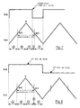
- Figure 7 shows in detail an example of detection of a 17th data bit.
- the signal received on the input RxD (top line), the value cnt of the counter (middle line), as well as the successive states of the state machine (bottom line) are represented.
- a transition is detected while the counter value is between N and N / 2.
- the 17th bit is useful here taken into account before the descent of the counter to N / 2.
- the successive states are therefore: "A", "B", “C”, "D” and "F".
- Figure 8 shows in detail the detection of a first and a second stop bit.
- the signal received on the input RxD (top line), the value cnt of the counter (middle line), as well as the successive states of the state machine (bottom line) are represented.
- no transition is detected during the nature detection window of the bit following the 16 th useful bit (ie, during the ascending phase of the counter, from N / 2 to N, neither during the downward phase, from N to N / 2).
- the first stop bit is taken into account here when the counter reaches N / 2.
- the successive states are therefore: "A", "B", “C”, “E” and "F”. Detection of the second stop bit is performed in the same way as that of the first stop bit.
- FIGS. 5 and 6 make it easier to visualize the operation of the decoder 14, each presenting a chronogram of the various input / output signals and intermediate signals to the decoder (see FIG. 3).
- FIG. 5 corresponds to the case of a frame comprising 17 useful bits and two stop bits.
- FIG. 6 corresponds to the case of a frame comprising 16 useful bits and a stop bit.
- the clock signal used to perform the coding (tclkmanchester), and which one seeks to reconstitute in the decoder.
Landscapes
- Engineering & Computer Science (AREA)
- Theoretical Computer Science (AREA)
- Synchronisation In Digital Transmission Systems (AREA)
- Dc Digital Transmission (AREA)
Applications Claiming Priority (4)
| Application Number | Priority Date | Filing Date | Title |
|---|---|---|---|
| FR0313689 | 2003-11-21 | ||
| FR0313689A FR2862820B1 (fr) | 2003-11-21 | 2003-11-21 | Circuit electronique de decodage d'un signal de donnees asynchrone biphase et procede de decodage correspondant, dispositif de controle d'un equipement |
| FR0406746 | 2004-06-21 | ||
| FR0406746A FR2862821B1 (fr) | 2003-11-21 | 2004-06-21 | Procede et circuit electronique de decodage d'une trame asynchrone biphase dont la longueur n'est pas connue a l'avance, application, programme d'ordinateur et moyen de stockage correspondants |
Publications (1)
| Publication Number | Publication Date |
|---|---|
| EP1533907A1 true EP1533907A1 (de) | 2005-05-25 |
Family
ID=34436810
Family Applications (1)
| Application Number | Title | Priority Date | Filing Date |
|---|---|---|---|
| EP04364070A Withdrawn EP1533907A1 (de) | 2003-11-21 | 2004-11-19 | Methode und Vorrichtung zur Dekodierung von asynchronen biphasen-kodierten Datenblöcken variabler Länge |
Country Status (3)
| Country | Link |
|---|---|
| US (1) | US7564936B2 (de) |
| EP (1) | EP1533907A1 (de) |
| FR (1) | FR2862821B1 (de) |
Families Citing this family (2)
| Publication number | Priority date | Publication date | Assignee | Title |
|---|---|---|---|---|
| US8680969B2 (en) * | 2009-03-20 | 2014-03-25 | Lutron Electronics Co., Inc. | Method of confirming that a control device complies with a predefined protocol standard |
| US9686742B1 (en) * | 2015-09-10 | 2017-06-20 | Mbit Wireless, Inc. | Method and apparatus to reduce power consumption in standby mode for wireless communication systems |
Citations (4)
| Publication number | Priority date | Publication date | Assignee | Title |
|---|---|---|---|---|
| US4241398A (en) * | 1978-09-29 | 1980-12-23 | United Technologies Corporation | Computer network, line protocol system |
| EP0245972A2 (de) * | 1986-04-29 | 1987-11-19 | AT&T Corp. | Übertragungskanal-Sendeempfänger |
| US5754764A (en) * | 1994-02-22 | 1998-05-19 | National Semiconductor Corp. | Combination of input output circuitry and local area network systems |
| EP1347609A1 (de) * | 2002-03-22 | 2003-09-24 | STMicroelectronics S.r.l. | Verfahren und vorrichtung zur Decodierung Manchesterkodiertesignalen |
Family Cites Families (5)
| Publication number | Priority date | Publication date | Assignee | Title |
|---|---|---|---|---|
| US6573948B1 (en) * | 1999-06-25 | 2003-06-03 | Samsung Electronics Co., Ltd. | Equalizing intermediate-frequency signals before demodulating them in a digital television receiver |
| US7050491B2 (en) * | 2001-10-15 | 2006-05-23 | Mcdonald James Douglas | Adaptive equalization of digital modulating signal recovered from amplitude-modulated signal subject to multipath |
| US6512944B1 (en) * | 2000-07-20 | 2003-01-28 | Cardiac Pacemakers, Inc. | Low distortion ECG filter |
| US20040225811A1 (en) * | 2001-04-04 | 2004-11-11 | Fosler Ross M. | Digital addressable lighting interface bridge |
| US20040268190A1 (en) * | 2003-05-19 | 2004-12-30 | International Business Machines Corporation | Adjusting parameters of a serial link |
-
2004
- 2004-06-21 FR FR0406746A patent/FR2862821B1/fr not_active Expired - Fee Related
- 2004-11-19 US US10/993,690 patent/US7564936B2/en not_active Expired - Fee Related
- 2004-11-19 EP EP04364070A patent/EP1533907A1/de not_active Withdrawn
Patent Citations (4)
| Publication number | Priority date | Publication date | Assignee | Title |
|---|---|---|---|---|
| US4241398A (en) * | 1978-09-29 | 1980-12-23 | United Technologies Corporation | Computer network, line protocol system |
| EP0245972A2 (de) * | 1986-04-29 | 1987-11-19 | AT&T Corp. | Übertragungskanal-Sendeempfänger |
| US5754764A (en) * | 1994-02-22 | 1998-05-19 | National Semiconductor Corp. | Combination of input output circuitry and local area network systems |
| EP1347609A1 (de) * | 2002-03-22 | 2003-09-24 | STMicroelectronics S.r.l. | Verfahren und vorrichtung zur Decodierung Manchesterkodiertesignalen |
Non-Patent Citations (1)
| Title |
|---|
| SASTRY R ET AL: "A low cost optical slotted ring network for RS-232C based communications", TENCON 1989, FOURTH IEEE REGION 10 INTERNATIONAL CONFERENCE, 22 November 1989 (1989-11-22), pages 646 - 649, XP010087882 * |
Also Published As
| Publication number | Publication date |
|---|---|
| FR2862821B1 (fr) | 2006-04-07 |
| FR2862821A1 (fr) | 2005-05-27 |
| US20050175134A1 (en) | 2005-08-11 |
| US7564936B2 (en) | 2009-07-21 |
Similar Documents
| Publication | Publication Date | Title |
|---|---|---|
| EP0881804B1 (de) | Verfahren und System zur Bestimmung des Symbolübertragungsformats in einem Übertragungssystem | |
| CA2889926C (fr) | Procede et dispositif de demodulation de signaux modules gfsk sur q etats | |
| EP1774458B1 (de) | Ladungsmodulation bei einem elektromagnetischen Transponder | |
| CH619330A5 (de) | ||
| EP3104569A1 (de) | Verfahren zur auswahl eines filters, der beim empfang eines rasters zu verwenden ist | |
| FR2818784A1 (fr) | Recepteur radiofrequence pour la telereleve de compteurs et methode de telereleve de compteurs comprenant un tel recepteur | |
| EP0727879A1 (de) | Vorrichtung zur Initialisierung eines Viterbi-Dekoders in einem Paketempfänger, entsprechender Empfänger und Verfahren zur Initialisierung | |
| FR3025923A1 (fr) | Discrimination et attenuation de pre-echos dans un signal audionumerique | |
| EP1533907A1 (de) | Methode und Vorrichtung zur Dekodierung von asynchronen biphasen-kodierten Datenblöcken variabler Länge | |
| EP2728821B1 (de) | Verfahren und Vorrichtung zur Entzerrung eines nicht-linearen Übertragungskanals | |
| EP1163771B1 (de) | Synchroner bpsk dekodierer | |
| EP0012880A1 (de) | Verfahren zum Dekodieren phasenkodierter, frequenzmoduliert kodierter oder in modifizierter Frequenzmodulation kodierter Binärdaten | |
| EP1536566B1 (de) | Elektronische Schaltung zur Dekodierung eines asynchronen Biphasensignals mit entsprechenden Verfahren und Steuerungsvorrichtung. | |
| EP0635184B1 (de) | Einrichtung zur datenuebertragung fuer netzwerken mit vielfachzugriff und verbesserter kollisionsaufloesung und verfahren dafuer | |
| CA2715810C (fr) | Procede et dispositif de delineation d'un flux de donnees et systeme de communication comprenant ledit dispositif. | |
| FR2707128A1 (fr) | Dispositif de détection de mot unique modulé en BPSK adapté à un modem analogique fonctionnant en mode TMDA et procédé de détection mis en Óoeuvre dans un tel dispositif. | |
| EP1720263B1 (de) | An ein Direct Sequence Spread Spectrum DSSS Übertragungssystem angepasstes Empfangsgerät mit Mechanismus zur Datenwiederherstellung | |
| EP0905946B1 (de) | Reglung der Abtastung von Biphasensignalen | |
| EP0648037A1 (de) | Phasenabgleich im Basisband | |
| CA3110838A1 (fr) | Procede de datation de signaux de telemesure | |
| EP0517556B1 (de) | Verfahren zur Demodulation von RDS-Signalen auf numerische Weise, und Demodulator zur Durchführung dieses Verfahrens | |
| FR2736478A1 (fr) | Procedes et dispositifs de codage et de decodage d'informations binaires en impulsions de durees variables | |
| EP0353109A1 (de) | Verfahren zur Demodulation und Demodulator für mit Hilfe eines Trägers konstanter Umhüllungsamplitude modulierte digitale Signale, die in Phase und/oder Frequenz kontinuierlich moduliert werden | |
| FR2725096A1 (fr) | Procede d'acquisition et de decodage de donnees numeriques et telecommande radiofrequence le mettant en oeuvre | |
| FR3022712A1 (fr) | Procede de demodulation auto-adaptative de signaux quasi-orthogonaux, unite de demodulation et recepteur de signaux radio |
Legal Events
| Date | Code | Title | Description |
|---|---|---|---|
| PUAI | Public reference made under article 153(3) epc to a published international application that has entered the european phase |
Free format text: ORIGINAL CODE: 0009012 |
|
| AK | Designated contracting states |
Kind code of ref document: A1 Designated state(s): AT BE BG CH CY CZ DE DK EE ES FI FR GB GR HU IE IS IT LI LU MC NL PL PT RO SE SI SK TR |
|
| AX | Request for extension of the european patent |
Extension state: AL HR LT LV MK YU |
|
| 17P | Request for examination filed |
Effective date: 20050629 |
|
| AKX | Designation fees paid |
Designated state(s): DE ES GB IT NL |
|
| 17Q | First examination report despatched |
Effective date: 20070924 |
|
| STAA | Information on the status of an ep patent application or granted ep patent |
Free format text: STATUS: THE APPLICATION IS DEEMED TO BE WITHDRAWN |
|
| 18D | Application deemed to be withdrawn |
Effective date: 20110601 |