EP1533874A2 - Laserdioden-Anordnung mit externem Resonator - Google Patents
Laserdioden-Anordnung mit externem Resonator Download PDFInfo
- Publication number
- EP1533874A2 EP1533874A2 EP04027585A EP04027585A EP1533874A2 EP 1533874 A2 EP1533874 A2 EP 1533874A2 EP 04027585 A EP04027585 A EP 04027585A EP 04027585 A EP04027585 A EP 04027585A EP 1533874 A2 EP1533874 A2 EP 1533874A2
- Authority
- EP
- European Patent Office
- Prior art keywords
- laser diode
- arrangement according
- laser
- resonator
- wavelength
- Prior art date
- Legal status (The legal status is an assumption and is not a legal conclusion. Google has not performed a legal analysis and makes no representation as to the accuracy of the status listed.)
- Withdrawn
Links
Images

Classifications
-
- H—ELECTRICITY
- H01—ELECTRIC ELEMENTS
- H01S—DEVICES USING THE PROCESS OF LIGHT AMPLIFICATION BY STIMULATED EMISSION OF RADIATION [LASER] TO AMPLIFY OR GENERATE LIGHT; DEVICES USING STIMULATED EMISSION OF ELECTROMAGNETIC RADIATION IN WAVE RANGES OTHER THAN OPTICAL
- H01S5/00—Semiconductor lasers
- H01S5/10—Construction or shape of the optical resonator, e.g. extended or external cavity, coupled cavities, bent-guide, varying width, thickness or composition of the active region
- H01S5/14—External cavity lasers
- H01S5/141—External cavity lasers using a wavelength selective device, e.g. a grating or etalon
-
- H—ELECTRICITY
- H01—ELECTRIC ELEMENTS
- H01S—DEVICES USING THE PROCESS OF LIGHT AMPLIFICATION BY STIMULATED EMISSION OF RADIATION [LASER] TO AMPLIFY OR GENERATE LIGHT; DEVICES USING STIMULATED EMISSION OF ELECTROMAGNETIC RADIATION IN WAVE RANGES OTHER THAN OPTICAL
- H01S5/00—Semiconductor lasers
- H01S5/06—Arrangements for controlling the laser output parameters, e.g. by operating on the active medium
- H01S5/062—Arrangements for controlling the laser output parameters, e.g. by operating on the active medium by varying the potential of the electrodes
- H01S5/0625—Arrangements for controlling the laser output parameters, e.g. by operating on the active medium by varying the potential of the electrodes in multi-section lasers
- H01S5/06255—Controlling the frequency of the radiation
-
- H—ELECTRICITY
- H01—ELECTRIC ELEMENTS
- H01S—DEVICES USING THE PROCESS OF LIGHT AMPLIFICATION BY STIMULATED EMISSION OF RADIATION [LASER] TO AMPLIFY OR GENERATE LIGHT; DEVICES USING STIMULATED EMISSION OF ELECTROMAGNETIC RADIATION IN WAVE RANGES OTHER THAN OPTICAL
- H01S5/00—Semiconductor lasers
- H01S5/06—Arrangements for controlling the laser output parameters, e.g. by operating on the active medium
- H01S5/068—Stabilisation of laser output parameters
- H01S5/0683—Stabilisation of laser output parameters by monitoring the optical output parameters
-
- H—ELECTRICITY
- H01—ELECTRIC ELEMENTS
- H01S—DEVICES USING THE PROCESS OF LIGHT AMPLIFICATION BY STIMULATED EMISSION OF RADIATION [LASER] TO AMPLIFY OR GENERATE LIGHT; DEVICES USING STIMULATED EMISSION OF ELECTROMAGNETIC RADIATION IN WAVE RANGES OTHER THAN OPTICAL
- H01S5/00—Semiconductor lasers
- H01S5/10—Construction or shape of the optical resonator, e.g. extended or external cavity, coupled cavities, bent-guide, varying width, thickness or composition of the active region
- H01S5/14—External cavity lasers
- H01S5/141—External cavity lasers using a wavelength selective device, e.g. a grating or etalon
- H01S5/143—Littman-Metcalf configuration, e.g. laser - grating - mirror
Definitions
- the invention relates to a laser diode arrangement with an external resonator according to the preamble of claim 1.
- semiconductor laser diode By operated in the flow direction semiconductor laser diode can be stimulated by means of Emission to generate coherent light. Due to the goodness of between the End surfaces of the semiconductor crystal formed resonator and due to the spontaneous However, emission within the laser diode usually has the emitted laser light relatively large line width. To reduce these, one usually uses one external resonator, which has wavelength-selective elements such as gratings and filters only Light of certain wavelengths - the resonator modes - fed back into the laser diode. This leads to an amplification of the stimulated emission on the respective selected wavelength. At the same time can be about the wavelength selective Element the emission wavelength over the gain range of the laser diode by vote.
- the Wavelength-selective elements include, for example, the Littrow- and the Littman arrangement.
- the Resonator length kept constant, so the number of nodes of the standing changes Light wave in the resonator, which is referred to as a mode jump.
- Another The reason for this lies in the non-vanishing reflectivity of the external Resonator facing antireflection-coated laser diode facet.
- the resonances The laser diode interfere with those of the external resonator, resulting in The result is that the wavelength is not continuously variable, but in discrete Steps jumps. Likewise, fluctuations in the output power of the laser diode occur which, for example, interferes with spectroscopic investigations effect.
- DE-U1-296 06 494 therefore discloses a tuning device for a semiconductor laser diode in Littman arrangement with a rotatably mounted about a fixed axis Low-tuning arm, on which a Resonatorendspiegel is attached, and with an optical Diffraction grating, the angle variable and with respect to the axis of rotation of the Abstimmarms is arranged variable in length.
- a adjusting device For the 1st to 3rd order, there is one adjusting device each, which is separate to be adjusted from each other.
- WO-A1-91 / 03848 is limited to the specification of a complex method for Determination of the fulcrum of a diffraction grating in a resonator in Littrow arrangement on a rotatably mounted about an axis or pivotally mounted Support arm is attached. More adjusting or adjusting means are not provided, so that Contributions of second and higher order of chromatic dispersion only conditionally be compensated. Furthermore, the non-vanishing reflectivity of the remains disregarded external cavity facing Laserdiodenfacette, so that when Tuning the wavelength continues power fluctuations and mode hops may occur.
- the aim of the invention is to overcome these and other disadvantages of the prior art and to provide a laser diode array with an external resonator, with the single-mode laser light can be generated, the wavelength of which is continuous and is tunable free of fashion jumps.
- the construction should be simple be economically feasible and easy to handle.
- Another object of the invention This is a significantly higher output power of the laser diode array to be able to achieve as well as an adjustment-invariant training of the external To create resonator.
- a laser diode arrangement for generating single-mode, tunable Laser radiation, with a laser diode, a back facet and a front facet and forms a first resonator, and with an external coupled thereto Resonator, the at least one optical transmission component and at least has a wavelength selective optical reflection element and of the Laser diode emitted laser light in the first resonator fed back, sees the Invention according to claim 1, that a means for varying the coupling quality of the first resonator is provided to the external resonator.
- the optical length of the first formed by the laser diode Resonators targeted to change so that both resonators on almost the entire wavelength range are always optimally coupled together.
- the means for varying the coupling quality on or in formed the first resonator which allows a compact structure.
- the device for varying the coupling quality is formed on or in the laser diode.
- the means for varying the coupling quality on the laser diode applied electrical terminal contact comprises, in each other independently controllable terminal segments is divided.
- the terminal contact according to claim 5 vertically is divided to the longitudinal axis of the laser diode, wherein the front facet facing first terminal segment has a length which is greater than the length of the other Terminal segment.
- the latter one can quickly and precisely the goodness of the first Resonators change, without affecting the main function of the laser diode.
- each terminal segment is via a control circuit acted upon by a control current, wherein the first terminal segment supplied control current according to claim 7 is constant.
- the other one Terminal segment supplied control current can, however, according to claim 8 in Dependence on the position of the wavelength-selective optical reflection elements relative to the laser diode via the control circuit change, whereby the of the laser coupled back to the external resonator from the laser diode in the area
- the second segment is more or less reinforced before it enters the main area the laser diode that is defined by the first terminal segment passes.
- the variation of the quality of the first resonator can be done passively according to claim 9, by the further terminal segment supplied control current and the position of the wavelength-selective optical reflection element in one over the Control circuit predeterminable relationship to each other. So if the reflection element, e.g. a grid that occupies a certain angular position, is at the another control segment of the control circuit a corresponding assigned Power applied. If one changes the angular position of the grating, e.g. in tuning of the laser, the control current from the control circuit is automatic tracked so that a always mode jump-free and power constant laser radiation is decoupled.
- the reflection element e.g. a grid that occupies a certain angular position
- the rear facet of the laser diode according to claim 11 mirrored and facing the external resonator front facet of the laser diode according to claim 12 is provided with an antireflection coating, wherein the Reflectivity of the back facet in accordance with claim 13 preferably less than 0.1% is.
- the laser diode according to claim 14 an active zone, which is a rectangular or trapezoidal shape.
- the latter prevents the oscillation of spatial modes, whereby the beam quality is further improved.
- Claim 15 also provides that the optical transmission component a Collimator is. This ensures that the exiting from the laser diode divergent Laser light as a parallel beam on the wavelength-selective reflection element falls.
- the latter is according to claim 16 preferably an optical diffraction grating and / or according to claim 17, a mirror. Accordingly forms the laser diode and the External resonator according to claim 18, a Littman or a Littrow arrangement.
- the laser diode is a quantum cascade laser, a quantum dot laser or a dilute nitride arsenide laser, which allows the use of larger or otherwise stored wavelength ranges.
- an important feature of the invention according to claim 20 is that the laser radiation can be decoupled via the rear facet of the laser diode, wherein the ratio the reflectivity of the rear facet to the reflectivity of the optical reflection element very much less than 1. This makes it possible, from the laser diode array a output much higher power, while at the same time fluctuations in light output and mode jumps in the spectral tuning curve of the laser system effectively avoided.
- the Ratio of the reflectivity of the back facet to the reflectivity of the optical reflection element is less than 0.1.
- the reflectivity of the rear facet preferably less than or equal to 1% and the reflectivity of the optical reflection element greater than or equal to 95%.
- Claim 23 provides that the laser diode has a length in the axial direction, the greater than or equal to 500 microns, which also leads to a significant increase in decoupled power contributes. At the same time, the line width of the emitted laser radiation.
- an optical Transmittance component arranged, e.g. a collimation lens. This ensures in that the divergent parallelizes laser light emerging from the back facet of the laser diode becomes. But you can also - depending on the use of the laser light - another Use the optics and / or add additional optical elements to the collimator.
- a laser diode array for generating single-mode, tunable laser radiation with a laser diode, which has a rear facet and a front facet and forms a first resonator, and with an external resonator coupled thereto, the at least one optical Transmission component and at least one wavelength-selective optical Reflecting element and emitted by the laser diode laser light in the first Resonator fed back, according to the invention provided that the transmission component associated with a condenser lens and a dispersive cylindrical lens, wherein the axis of the cylindrical lens is substantially parallel to the optical Reflection elements is arranged.
- EP-A2-0 347 213 proposes a laser diode system with an external resonator in Littrow arrangement, which in addition to a Kollimationsoptik and a Diffraction grating has an anamorphic transmission region, the Laser beam is formed such that it forms a line focus on the diffraction grating.
- a cylindrical converging lens is arranged behind the collimating lens, whose optical axis is perpendicular to the grid lines of the resonator grid.
- additional Prisms serve as beam expander to further increase the width of the laser beam.
- the optical system according to the invention overcomes such disadvantages. She lets herself form extremely compact and robust, whereby the entire laser array itself mechanical shocks and vibrations easily withstand. Even the use in usually harsh industrial environments or in space is possible. That of the wavelength-selective element feedback light is always accurate to the light-emitting Focused laser facet, so that in the long run neither mode jumps still power losses occur. Elaborate compensation mechanisms are not required.
- a further embodiment of the invention provides that the optical reflection element is formed by two partial lattices, which are at an angle of 90 ° to each other are arranged.
- the laser arrangement is opposite to the adjustment Tilting of a hat grid forming sub-grid perpendicular to the grid lines.
- the generally designated 10 in Fig. 1 laser diode array for generating single-mode, tunable laser radiation 15 is formed as a Littman arrangement.
- a semiconductor laser diode 11 mounted on a support 12, e.g. a base plate or a mounting block is attached.
- the rear facet 16 of the laser diode 11 is provided with a reflective coating whose reflectivity is preferably close to 100%.
- the front facet 17, however, is provided with an antireflection coating whose Reflectivity is less than 0.1%. Both facets 16, 17 form the end surfaces a first resonator R1 whose length is of the length D of the semiconductor crystal of the Laser diode 11 is determined.
- the laser light 13 emitted by the laser facet 17 is of an optical transmission component 30 in the form of a rotationally symmetrical converging lens 32 on the Surface of a diffraction optical grating 40 focused as wavelength-selective Reflection element together with a mirror 50 part of a external resonator R2.
- the reflectivity of the planar grid 40 is preferably about 5%, so that a large part of the laser light zeroth order than useful beam 15th is decoupled.
- Light 14 of the first diffraction order is of the Grid 40 is directed to the mirror 50, reflected by this and - after it has been removed from the Grating 40 was diffracted a second time - fed back into the laser diode 11.
- the grid 40 is preferably mounted on a support 44 which by means of adjustment or Adjusting means 46, e.g. a translation table to at least one axis 43 parallel to the grid lines 42 pivoted and / or linear in different directions can be moved.
- the grid lines 42 of the grid 40 are perpendicular to Longitudinal axis A of the laser diode 11.
- the mirror 50 is mounted on a support arm 52 which is pivotable about an axis 54 is stored. The latter runs parallel to the mirror plane. If the support arm 52 to the Axis 54 pivots, changes from the grid 40 into the laser diode eleventh fed back wavelength. The laser 10 is detuned. At the same time changes however, the wavelength determined by the length of the external resonator R2 by a corresponding displacement of the grating 40 relative to the mirror 50 or relative to its axis of rotation 54 involving multiple dispersion orders can be compensated.
- a dispersing cylindrical lens 34 is arranged, the axis Z parallel to the grid lines 42 of the grid 40 runs. Position and focus of the cylindrical lens 34 are chosen that a line focus is produced on the grating 40, i. that of the laser facet 17 emitted laser light 13 is transmitted by the transmission component 30 as (not shown) narrow line shown on the grid 40, the height of the line is much smaller is as its width. The latter determines the selectivity of the grating 40.
- the laser 10 becomes altogether adjustment-invariant against tilting of the grid 40 about an axis perpendicular to the Grid lines 42, for example, when pivoting the grid 40 about the axis 43rd or caused by shocks.
- the first resonator R1 formed by the laser diode 11 is with a device 60, with which one the coupling quality of the first resonator R1 can specifically vary to the external resonator R2.
- the device 60 essentially comprises an applied on the laser diode 11 electrical Terminal contact 61, which is perpendicular to the longitudinal axis A in two separate terminal segments 62, 63, and a control circuit 66. Each terminal segment 62, 63 is connected via a connecting line 64, 65 to the control circuit 66. With this you can the terminal segments 62, 63 independently with a Apply control or segment current. It can be seen in Fig.
- the segment current is held at the first connection segment 62 constant, so you can by changing the second terminal segment 63rd supplied segment current fed back from the external resonator R2 Laser light in the control segment S amplify more or less before entering the Main segment H of the laser diode 11 passes.
- the current change at the second Terminal segment 63 leads to a change in temperature in the control segment S and thus causing a temperature change in the active region of the laser diode 11.
- changes the optical length of the laser diode 11 and the resonator R1 therefore always optimally coupled to the external resonator R2.
- Due to the separately controllable currents at the terminal segments 62, 63 is also a targeted variation of the capacity of the first resonator R1 for the of reaches the external resonator R2 fed back laser light, resulting in a significant increase in the laser light output leads. For example, you can at a deteriorating coupling the power supply to the second terminal segment 63 increase. Improves the coupling, the segment current at the other Tuning the wavelength down again.
- the control of the segment currents at the terminal segments 62, 63 assumes the Control circuit 66, which for this purpose with a (not shown) electronic control is provided.
- the Control circuit 66 which for this purpose with a (not shown) electronic control is provided.
- the current and the position of the grid 40 and the mirror 50 are in a predeterminable via the control circuit 66 relationship to each other. This ensures that when tuning the laser 10, the coupling quality always correctly tracked.
- the power of the decoupled laser radiation 15th measured and the second terminal segment 63 supplied current in dependence from the detected power and depending on the angular position of the grid 40 and / or the Mirror 50 tracked.
- the laser diode array 10 thus always emits one single-mode laser radiation 15, which is tunable free of mode jumps. costly mathematical calculations to determine the axis of rotation 54 for the mirror or a costly tracking of the grid 40 is no longer required.
- the entire assembly 10 can be extremely compact and inexpensive to implement and just as easy to handle.
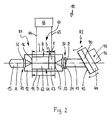
- the laser diode assembly 10 forms a Littrow arrangement.
- This consists essentially of the laser diode 11 and the external Resonator R2, which consists of the optical transmission component 30, consisting of Converging lens 32 and dispersive cylindrical lens 34, and the wavelength-selective optical reflection element 40 in the form of a plane diffraction grating as Resonatorendspiegel is formed.
- the coupling of the laser light 15 can - as well as in the Littman arrangement of Fig. 1 - via the diffraction grating 40 done (not ) Shown.
- the laser radiation 15 via the rear facet 16 of the laser diode 11 is decoupled.
- the ratio of the reflectivity of the back facet is 16 to the reflectivity of the optical grating 40 is much smaller than 1, preferably very much smaller than 0.1. Specifically, this relationship is achieved by the fact that the Reflectance of the rear facet 16 is less than or equal to 1% and the reflectivity of the grid 40 is greater than or equal to 95%.
- much of the external resonator R2 becomes fed back more light into the laser diode 11, thereby laser light 13 with a emitted much higher power.
- a further increase in performance is achieved when the laser diode 11 in the axial direction A has a length D which is greater than or equal to 500 microns.
- laser radiation 15 is in the region of the rear facet 16 an optical transmission component 70, e.g. a collimating lens 72.
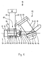
- Fig. 3 shows another variant for the realization of Justageinvarianz.
- the plane diffraction grating 40 of the Littrow arrangement of Fig. 2 replaced by a hat rail, which is formed by two partial gratings 47, 48, in are arranged at an angle of 90 ° to each other.
- Incident collimated monochromatic Light is offset in parallel and reflected back in the direction of the it came.
- the laser 10 is invariant against tilting of the Hutgitters 40 perpendicular to the grid lines 42, while the tuning behavior at Pivoting the grid 40 around an axis parallel to the grid lines 42 obtained remains.
- the invention is not limited to one of the above-described embodiments, but changeable in many ways.
- This is the embodiment of FIG. 1 in that the preferably rotationally symmetrical converging lens 32 between the laser diode 11 and the cylindrical lens 34 is arranged. But it can also be cheap when the cylindrical lens 34 between the laser diode 11 and the converging lens 32nd arranges.
- it is expedient to use the lens 32 as form aspherical lens.
- the laser diode 11 preferably has an active region of a rectangular shape. Around To prevent the oscillation of spatial modes, one can see the active zone form trapezoidal. This also results in improved performance.
- the Laser diode 11 is a quantum cascade laser. With this can be wavelength ranges from 4 ⁇ m to 12 ⁇ m, which is not the case with conventional laser diodes is possible.
- the modification of the laser diode 11 according to the invention provides for an always mode-jump-free tunability.
- a laser diode 11 also use a quantum dot laser or a dilute nitride arsenide laser. This may also result in further application-specific advantages.
- a laser diode arrangement 10 for generating single-mode, tunable laser radiation 15 has a laser diode 11 having a scrubfacette 16th and a front facet 17 and forms a first resonator R1. Further, a provided thereon external resonator R2, which is at least one optical Transmission component 30 and at least one wavelength-selective optical Reflecting element 40, 50 and emitted from the laser diode 11 laser light 13th fed back into the first resonator R1.
- a device 60 for varying the Coupling quality of the first resonator R1 to the external resonator R2 is provided.
- the device 60 is preferably one on the laser diode 11 applied electrical terminal contact 61, which is independent of each other controllable terminal segments 62, 63 is divided.
- Each terminal segment 62, 63 is acted upon via a control circuit 66 with a control current, wherein the the first terminal segment 62 supplied control current is constant and the the another terminal segment 63 supplied control current in dependence on the Position of the wavelength-selective optical reflection elements 40, 50 with respect to Laser diode 11 of the control circuit 66 is variable.
Landscapes
- Physics & Mathematics (AREA)
- Condensed Matter Physics & Semiconductors (AREA)
- General Physics & Mathematics (AREA)
- Electromagnetism (AREA)
- Optics & Photonics (AREA)
- Semiconductor Lasers (AREA)
Abstract
Description
- Fig. 1
- eine schematische Darstellung einer Laserdioden-Anordnung in Littman-Anordnung,
- Fig. 2
- eine schematische Darstellung einer Laserdioden-Anordnung in Littrow-Anordnung,
- Fig. 3
- eine schematische Darstellung eines Hutgitters für eine Laserdioden-Anordnung in Littrow-Anordnung und
- Fig. 4
- das Hutgitter von Fig. 3 in einer Draufsicht.
- A
- Längsachse (Laserdiode)
- D
- Länge (Laserdiode)
- H
- Hauptsegment
- I
- Länge (Anschlußsegment)
- L
- Länge (Anschlußsegment)
- R1
- Resonator
- R2
- externer Resonator
- S
- Steuersegment
- Z
- Linsenachse
- 10
- Laserdioden-Anordnung
- 11
- Laserdiode
- 12
- Träger
- 13
- Laserstrahlung
- 14
- Laserstrahlung
- 15
- Laserlicht / Nutzstrahl
- 16
- Rückfacette
- 17
- Frontfacette
- 30
- optische Transmissionskomponente
- 32
- Kollimator / asphärische Linse
- 34
- Zylinderlinse
- 40
- optisches Reflexionselement /Gitter
- 42
- Gitterlinien
- 43
- Drehachse
- 44
- Träger
- 46
- Justiermittel
- 47
- Teilgitter
- 48
- Teilgitter
- 50
- Spiegel
- 52
- Tragarm
- 54
- Drehachse
- 60
- Einrichtung zur Variation der Ankopplungsgüte
- 61
- elektrische Anschlußkontakte
- 62
- Anschlußsegment
- 63
- Anschlußsegment
- 64
- Anschlußleitung
- 65
- Anschlußleitung
- 66
- Steuerung/Regler
- 70
- optische Transmissionskomponente
- 72
- Kollimator / asphärische Linse
Claims (28)
- Laserdioden-Anordnung (10) zur Erzeugung von einmodiger, durchstimmbarer Laserstrahlung (15), mit einer Laserdiode (11), die eine Rückfacette (16) und eine Frontfacette (17) aufweist und einen ersten Resonator (R1) bildet, und mit einem daran angekoppelten externen Resonator (R2), der wenigstens eine optische Transmissionskomponente (30) und wenigstens ein wellenlängenselektives optisches Reflexionselement (40, 50) aufweist und von der Laserdiode (11) emittiertes Laserlicht (13) in den ersten Resonator (R1) zurückkoppelt, dadurch gekennzeichnet, daß eine Einrichtung (60) zur Variation der Ankopplungsgüte des ersten Resonators (R1) an den externen Resonator (R2) vorgesehen ist.
- Anordnung nach Anspruch 1, dadurch gekennzeichnet, daß die Einrichtung (60) zur Variation der Ankopplungsgüte an oder in dem ersten Resonator (R1) ausgebildet ist.
- Anordnung nach Anspruch 1 oder 2, dadurch gekennzeichnet, daß die Einrichtung (60) zur Variation der Ankopplungsgüte an oder in der Laserdiode (11) ausgebildet ist.
- Anordnung nach Anspruch 3, dadurch gekennzeichnet, daß die Einrichtung (60) zur Variation der Ankopplungsgüte einen auf der Laserdiode (11) aufgebrachten elektrischen Anschlußkontakt (61) umfaßt, der in voneinander unabhängig ansteuerbare Anschlußsegmente (62, 63) unterteilt ist.
- Anordnung nach Anspruch 4, dadurch gekennzeichnet, daß der Anschlußkontakt (61) senkrecht zur Längsachse (A) der Laserdiode (11) unterteilt ist, wobei das der Rückfacette (16) zugewandte erste Anschlußsegment (62) eine Länge (L) aufweist, die größer ist als die Länge (I) des weiteren Anschlußsegments (63).
- Anordnung nach Anspruch 4 oder 5, dadurch gekennzeichnet, daß jedes Anschlußsegment (62, 63) über eine Regelschaltung (66) mit einem Steuerstrom beaufschlagbar ist.
- Anordnung nach einem der Ansprüche 4 bis 6, dadurch gekennzeichnet, daß der dem ersten Anschlußsegment (62) zugeführte Steuerstrom konstant ist.
- Anordnung nach einem der Ansprüche 4 bis 7, dadurch gekennzeichnet, daß der dem weiteren Anschlußsegment (63) zugeführte Steuerstrom in Abhängigkeit von der Position der wellenlängenselektiven optischen Reflexionselemente (40, 50) in Bezug zur Laserdiode (11) von der Regelschaltung (66) veränderbar ist.
- Anordnung nach Anspruch 8, dadurch gekennzeichnet, daß der dem weiteren Anschlußsegment (63) zugeführte Steuerstrom und die Position der bzw. des wellenlängenselektiven optischen Reflexionselements (40, 50) in einer über die Regelschaltung (66) vorgebbaren Beziehung zueinander stehen.
- Anordnung nach einem der Ansprüche 4 bis 9, dadurch gekennzeichnet, daß der dem weiteren Anschlußsegment (63) zugeführte Steuerstrom in Abhängigkeit von der Leistung der aus der Laserdioden-Anordnung (10) ausgekoppelten Laserstrahlung (15) von der Regelschaltung (66) veränderbar ist.
- Anordnung nach einem der Ansprüche 1 bis 10, dadurch gekennzeichnet, daß die Rückfacette (16) der Laserdiode (11) verspiegelt ist.
- Anordnung nach einem der Ansprüche 1 bis 11, dadurch gekennzeichnet, daß die dem externen Resonator (R2) zugewandte Frontfacette (17) der Laserdiode (11) mit einer Antireflexionsbeschichtung versehen ist.
- Anordnung nach Anspruch 12, dadurch gekennzeichnet, daß die Reflektivität der antireflexionsbeschichteten Frontfacette (17) kleiner als 0,001 beträgt.
- Anordnung nach einem der Ansprüche 1 bis 13, dadurch gekennzeichnet, daß die Laserdiode (11) eine aktive Zone aufweist, die eine rechteckige oder trapezförmige Form hat.
- Anordnung nach einem der Ansprüche 1 bis 14, dadurch gekennzeichnet, daß die optische Transmissionskomponente (30) einen Kollimator (32) aufweist.
- Anordnung nach einem der Ansprüche 1 bis 15, dadurch gekennzeichnet, daß das wellenlängenselektive Reflexionselement (40) ein optisches Beugungsgitter ist.
- Anordnung nach einem der Ansprüche 1 bis 16, dadurch gekennzeichnet, daß das wellenlängenselektive Reflexionselement (50) ein Spiegel ist.
- Anordnung nach einem der Ansprüche 1 bis 17, dadurch gekennzeichnet, daß die Laserdiode (11) und der externe Resonator (R2) eine Littman- oder eine Littrow-Anordnung bilden.
- Anordnung nach einem der Ansprüche 1 bis 18, dadurch gekennzeichnet, daß die Laserdiode (11) ein Quantenkaskadenlaser, ein Quantenpunktlaser oder ein Dilute-Nitrid-Arsenid-Laser ist.
- Anordnung nach einem der Ansprüche 1 bis 19, dadurch gekennzeichnet, daß die Laserstrahlung (15) über die Rückfacette (16) der Laserdiode (11) auskoppelbar ist, wobei das Verhältnis der Reflektivität der Rückfacette (16) zur Reflektivität des optischen Reflexionselements (40) sehr viel kleiner als 1 ist.
- Anordnung nach Anspruch 1, dadurch gekennzeichnet, daß das Verhältnis der Reflektivität der Rückfacette (16) zur Reflektivität des optischen Reflexionselements (40) kleiner als 0,1 ist.
- Anordnung nach Anspruch 1 oder 2, dadurch gekennzeichnet, daß die Reflektivität der Rückfacette (16) kleiner oder gleich 0,01 und die Reflektivität des optischen Reflexionselements (40) größer oder gleich 0,95 ist.
- Anordnung nach einem der Ansprüche 1 bis 3, dadurch gekennzeichnet, daß die Laserdiode (11) in Axialrichtung (A) eine Länge (D) aufweist, die größer oder gleich 500 µm ist.
- Anordnung nach einem der Ansprüche 1 bis 4, dadurch gekennzeichnet, daß im Bereich der Rückfacette (16) eine optische Transmissionskomponente (70) angeordnet ist, z.B. eine Kollimationslinse (72).
- Laserdioden-Anordnung (10) zur Erzeugung von einmodiger, durchstimmbarer Laserstrahlung (15), mit einer Laserdiode (11), die eine Rückfacette (16) und eine Frontfacette (17) aufweist und einen ersten Resonator (R1) bildet, und mit einem daran angekoppelten externen Resonator (R2), der wenigstens eine optische Transmissionskomponente (30) und wenigstens ein wellenlängenselektives optisches Reflexionselement (40, 50) aufweist und von der Laserdiode (11) emittiertes Laserlicht (13) in den ersten Resonator (R1) zurückkoppelt, insbesondere nach einem Ansprüche 1 bis 25, dadurch gekennzeichnet, daß der Transmissionskomponente (30) eine Sammellinse (32) und eine zerstreuende Zylinderlinse (34) zugeordnet ist, wobei die Achse (Z) der Zylinderlinse (34) im wesentlichen parallel zu den optischen Reflexionselementen (40, 50) angeordnet ist.
- Anordnung nach Anspruch 25, dadurch gekennzeichnet, daß die Zylinderlinse (34) zwischen der Laserdiode (11) und der Sammellinse (32) angeordnet ist.
- Anordnung nach Anspruch 25, dadurch gekennzeichnet, daß die Sammellinse (32) zwischen der Laserdiode (11) und der Zylinderlinse (34) angeordnet ist.
- Anordnung nach wenigstens einem der Ansprüche 1 bis 27, dadurch gekennzeichnet, daß das optische Reflexionselement (40) von zwei Teilgittern (47, 48) gebildet wird, die in einem Winkel von 90° zueinander angeordnet sind.
Applications Claiming Priority (2)
| Application Number | Priority Date | Filing Date | Title |
|---|---|---|---|
| DE20317904U | 2003-11-19 | ||
| DE20317904U DE20317904U1 (de) | 2003-11-19 | 2003-11-19 | Laserdioden-Anordnung mit externem Resonator |
Publications (2)
| Publication Number | Publication Date |
|---|---|
| EP1533874A2 true EP1533874A2 (de) | 2005-05-25 |
| EP1533874A3 EP1533874A3 (de) | 2005-09-07 |
Family
ID=34399765
Family Applications (1)
| Application Number | Title | Priority Date | Filing Date |
|---|---|---|---|
| EP04027585A Withdrawn EP1533874A3 (de) | 2003-11-19 | 2004-11-19 | Laserdioden-Anordnung mit externem Resonator |
Country Status (3)
| Country | Link |
|---|---|
| US (2) | US20050105566A1 (de) |
| EP (1) | EP1533874A3 (de) |
| DE (1) | DE20317904U1 (de) |
Families Citing this family (28)
| Publication number | Priority date | Publication date | Assignee | Title |
|---|---|---|---|---|
| US20050163172A1 (en) * | 2004-01-27 | 2005-07-28 | Joachim Sacher | High-power laser diode arrangement with external resonator |
| JP2005243756A (ja) * | 2004-02-25 | 2005-09-08 | Mitsubishi Electric Corp | 外部共振器型波長可変半導体レーザ装置 |
| WO2006113398A2 (en) * | 2005-04-19 | 2006-10-26 | Bookham Technology Plc | Electronic wavelength marker system and method |
| US7767444B2 (en) * | 2005-05-31 | 2010-08-03 | Nanyang Technological University | Cell analysis using laser with external cavity |
| US7466734B1 (en) * | 2005-06-15 | 2008-12-16 | Daylight Solutions, Inc. | Compact external cavity mid-IR optical lasers |
| US7492806B2 (en) * | 2005-06-15 | 2009-02-17 | Daylight Solutions, Inc. | Compact mid-IR laser |
| US7535656B2 (en) | 2005-06-15 | 2009-05-19 | Daylight Solutions, Inc. | Lenses, optical sources, and their couplings |
| US7733924B2 (en) * | 2005-08-15 | 2010-06-08 | William Marsh Rice University | Piezo activated mode tracking system for widely tunable mode-hop-free external cavity mid-IR semiconductor lasers |
| US20090201967A1 (en) * | 2006-05-24 | 2009-08-13 | Leibniz Universitat Hannover | Laser device comprising a diffraction grating and coupled laser resonators |
| US7903704B2 (en) * | 2006-06-23 | 2011-03-08 | Pranalytica, Inc. | Tunable quantum cascade lasers and photoacoustic detection of trace gases, TNT, TATP and precursors acetone and hydrogen peroxide |
| DE102007013173A1 (de) | 2007-03-20 | 2008-09-25 | Rottenkolber, Matthias, Dr. | Durchstimmbarer Halbleiterlaser |
| DE102007013470A1 (de) | 2007-03-21 | 2008-09-25 | Rottenkolber, Matthias, Dr. | Direkt durchstimmbarer Halbleiterlaser mit Piezotranslator |
| US7869474B2 (en) * | 2008-01-10 | 2011-01-11 | William Marsh Rice University | Fast wavelength tuning techniques for external cavity lasers |
| US7848382B2 (en) * | 2008-01-17 | 2010-12-07 | Daylight Solutions, Inc. | Laser source that generates a plurality of alternative wavelength output beams |
| US8774244B2 (en) | 2009-04-21 | 2014-07-08 | Daylight Solutions, Inc. | Thermal pointer |
| WO2011000153A1 (zh) * | 2009-06-30 | 2011-01-06 | 山东远普光学股份有限公司 | 连续无跳模可调谐光栅外腔半导体激光器 |
| US8718105B2 (en) * | 2010-03-15 | 2014-05-06 | Daylight Solutions, Inc. | Laser source that generates a rapidly changing output beam |
| JP5463473B2 (ja) * | 2010-03-18 | 2014-04-09 | サンテック株式会社 | 光断層画像表示システム |
| CN101826701A (zh) * | 2010-05-06 | 2010-09-08 | 山东远普光学股份有限公司 | 一种无跳模连续调谐半导体激光器 |
| US8335413B2 (en) | 2010-05-14 | 2012-12-18 | Daylight Solutions, Inc. | Optical switch |
| WO2012006346A1 (en) | 2010-07-07 | 2012-01-12 | Daylight Solutions, Inc. | Multi-wavelength high output laser source assembly with precision output beam |
| CN102340098A (zh) * | 2010-07-21 | 2012-02-01 | 北京优立光太科技有限公司 | 半导体激光放大器 |
| US9225148B2 (en) | 2010-09-23 | 2015-12-29 | Daylight Solutions, Inc. | Laser source assembly with thermal control and mechanically stable mounting |
| US8467430B2 (en) | 2010-09-23 | 2013-06-18 | Daylight Solutions, Inc. | Continuous wavelength tunable laser source with optimum orientation of grating and gain medium |
| US9042688B2 (en) | 2011-01-26 | 2015-05-26 | Daylight Solutions, Inc. | Multiple port, multiple state optical switch |
| DE102018112561A1 (de) * | 2018-05-25 | 2019-11-28 | Sacher Lasertechnik Gmbh | Laserdioden-Anordnung mit einem externen Resonator |
| IT201900002013A1 (it) * | 2019-02-12 | 2020-08-12 | Laboratorio Europeo Di Spettroscopie Non Lineari Lens | Dispositivo laser a cavita' esterna, sistema e procedimento corrispondenti |
| CN109950784B (zh) * | 2019-04-10 | 2021-05-28 | 上海禾赛科技股份有限公司 | 激光器和激光雷达 |
Family Cites Families (6)
| Publication number | Priority date | Publication date | Assignee | Title |
|---|---|---|---|---|
| US5392308A (en) * | 1993-01-07 | 1995-02-21 | Sdl, Inc. | Semiconductor laser with integral spatial mode filter |
| US5537432A (en) * | 1993-01-07 | 1996-07-16 | Sdl, Inc. | Wavelength-stabilized, high power semiconductor laser |
| DE69521157T2 (de) * | 1994-02-18 | 2001-11-08 | Canon K.K., Tokio/Tokyo | Polarisationsselektiver Halbleiterlaser, Lichtsender und optisches Kommunikationssystem unter Verwendung dieses Lasers |
| US5579327A (en) * | 1994-06-06 | 1996-11-26 | Anritsu Corporation | External-cavity tunable wavelength light source using semiconductor laser having phase adjustment area |
| US5867512A (en) * | 1997-02-10 | 1999-02-02 | Sacher; Joachim | Tuning arrangement for a semiconductor diode laser with an external resonator |
| JP3197869B2 (ja) * | 1998-03-31 | 2001-08-13 | アンリツ株式会社 | 波長可変レーザ光源装置 |
-
2003
- 2003-11-19 DE DE20317904U patent/DE20317904U1/de not_active Expired - Lifetime
-
2004
- 2004-02-20 US US10/783,879 patent/US20050105566A1/en not_active Abandoned
- 2004-02-20 US US10/784,029 patent/US20050105567A1/en not_active Abandoned
- 2004-11-19 EP EP04027585A patent/EP1533874A3/de not_active Withdrawn
Also Published As
| Publication number | Publication date |
|---|---|
| EP1533874A3 (de) | 2005-09-07 |
| DE20317904U1 (de) | 2005-03-31 |
| US20050105567A1 (en) | 2005-05-19 |
| US20050105566A1 (en) | 2005-05-19 |
Similar Documents
| Publication | Publication Date | Title |
|---|---|---|
| EP1533874A2 (de) | Laserdioden-Anordnung mit externem Resonator | |
| DE69510420T2 (de) | Wellenlängenabstimmbare Monomodlaserquelle mit selbstausrichtendem externen Resonator | |
| EP0829120B1 (de) | Durchstimmbare, justierstabile laserlichtquelle mit spektral gefiltertem ausgang | |
| DE69514042T2 (de) | Wellenlängenabstimmbare Lichtquelle mit externem Resonator unter Verwendung eines Halbleiterlasers mit einer Region zur Einstellung der Phase | |
| EP2973899B1 (de) | Vorrichtung zur wellenlängenkopplung von laserstrahlen | |
| DE69902963T2 (de) | Abstimmbare Laserquelle mit breitbandiger und kontinuierlicher Variation der Oszillationswellenlänge | |
| DE68912656T2 (de) | Durch Beugungsgitter abgestimmter Laser. | |
| DE69620386T2 (de) | Laser mit einem passiven optischen resonator | |
| DE60020069T2 (de) | Verstimmbare Laserquelle | |
| DE69610417T2 (de) | Technik zur kopplung einer grossflächigen laserdiode mit externem resonator an einen passiven optischen resonator | |
| EP3804054A1 (de) | Laserdioden-anordnung mit einem externen resonator | |
| DE112018006226T5 (de) | Optischer Frequenzkamm-Aufbau und Verwendung eines externen Hohlraums zur Dispersionskompensation und Frequenzeinstellung | |
| DE102011085614B4 (de) | Lasersystem mit Resonator | |
| EP2006964B1 (de) | Abstimmbares Diodenlasersystem mit externem Resonator | |
| EP0801451B1 (de) | Abstimmvorrichtung | |
| DE19548647C2 (de) | Durchstimmbare, justierstabile Halbleiterlaserlichtquelle sowie ein Verfahren zur optisch stabilen, weitgehend kontinuierlichen Durchstimmung von Halbleiterlasern | |
| EP1533875B1 (de) | Laserdioden-Anordnung mit externem Resonator | |
| DE19509922C2 (de) | Abstimmvorrichtung für einen Halbleiterlaser mit externem Resonator | |
| DE112005002283T5 (de) | Modenselektives Frequenzabstimmungssystem | |
| DE60216158T2 (de) | Bezüglich wellenlänge abstimmbarer resonator mit einem prisma | |
| DE102008036254A1 (de) | Halbleiterlaser | |
| DE19860895B4 (de) | Modensprungfreie durchstimmbare und spektral reine Laserlichtquelle | |
| WO2008074452A2 (de) | Laserlichtquelle | |
| DE29606494U1 (de) | Abstimmvorrichtung | |
| DE202004001230U1 (de) | Laserdioden-Anordnung mit externem Resonator |
Legal Events
| Date | Code | Title | Description |
|---|---|---|---|
| PUAI | Public reference made under article 153(3) epc to a published international application that has entered the european phase |
Free format text: ORIGINAL CODE: 0009012 |
|
| AK | Designated contracting states |
Kind code of ref document: A2 Designated state(s): AT BE BG CH CY CZ DE DK EE ES FI FR GB GR HU IE IS IT LI LU MC NL PL PT RO SE SI SK TR |
|
| AX | Request for extension of the european patent |
Extension state: AL HR LT LV MK YU |
|
| PUAL | Search report despatched |
Free format text: ORIGINAL CODE: 0009013 |
|
| AK | Designated contracting states |
Kind code of ref document: A3 Designated state(s): AT BE BG CH CY CZ DE DK EE ES FI FR GB GR HU IE IS IT LI LU MC NL PL PT RO SE SI SK TR |
|
| AX | Request for extension of the european patent |
Extension state: AL HR LT LV MK YU |
|
| AKX | Designation fees paid | ||
| STAA | Information on the status of an ep patent application or granted ep patent |
Free format text: STATUS: THE APPLICATION IS DEEMED TO BE WITHDRAWN |
|
| 18D | Application deemed to be withdrawn |
Effective date: 20060308 |
|
| REG | Reference to a national code |
Ref country code: DE Ref legal event code: 8566 |