EP1533766A1 - Signalgerät - Google Patents
Signalgerät Download PDFInfo
- Publication number
- EP1533766A1 EP1533766A1 EP04026044A EP04026044A EP1533766A1 EP 1533766 A1 EP1533766 A1 EP 1533766A1 EP 04026044 A EP04026044 A EP 04026044A EP 04026044 A EP04026044 A EP 04026044A EP 1533766 A1 EP1533766 A1 EP 1533766A1
- Authority
- EP
- European Patent Office
- Prior art keywords
- signal
- sensor
- generator
- signal device
- control
- Prior art date
- Legal status (The legal status is an assumption and is not a legal conclusion. Google has not performed a legal analysis and makes no representation as to the accuracy of the status listed.)
- Granted
Links
Images
Classifications
-
- G—PHYSICS
- G08—SIGNALLING
- G08B—SIGNALLING SYSTEMS, e.g. PERSONAL CALLING SYSTEMS; ORDER TELEGRAPHS; ALARM SYSTEMS
- G08B7/00—Signalling systems according to two or more of groups G08B3/00 - G08B6/00
- G08B7/06—Signalling systems according to two or more of groups G08B3/00 - G08B6/00 using electric transmission, e.g. involving audible and visible signalling through the use of sound and light sources
-
- G—PHYSICS
- G07—CHECKING-DEVICES
- G07C—TIME OR ATTENDANCE REGISTERS; REGISTERING OR INDICATING THE WORKING OF MACHINES; GENERATING RANDOM NUMBERS; VOTING OR LOTTERY APPARATUS; ARRANGEMENTS, SYSTEMS OR APPARATUS FOR CHECKING NOT PROVIDED FOR ELSEWHERE
- G07C3/00—Registering or indicating the condition or the working of machines or other apparatus, other than vehicles
Definitions
- the invention relates to a signaling device according to the preamble of claim 1.
- Signal devices in particular for displaying operating states in machines and plants with at least two different ones Signal generators for at least two different ones Signals are already commercially available.
- a so-called signal tower for modular construction with the Publication EP 0 755 494 B1 has become known in the various segments to a signal light with socket and lid can be combined.
- Signal devices also include acoustic signal generators, such as For example, piezo buzzer or the like to find.
- Such signaling devices are u.a. used to at Machines and installations the operating conditions or defects to indicate to certain operators and, where appropriate, To generate warning signals.
- the object of the invention is therefore a signal device to propose, in which the signal function also at Interference from the environment, such as ambient light or Environmental noise is guaranteed.
- This task is based on a signaling device of initially mentioned type by the characterizing features of claim 1.
- an inventive Signal device characterized in that at least one environmental sensor to detect the perception of the signal interfering disturbance from the environment of Signaling device is present and a control unit for a disturbance variable-dependent signal control is provided.
- control unit designed so that the Signaling and sensor intermittent interrogation occur.
- an intermittent sequence becomes Make sure that the environmental sensor is the appropriate one Interference from the environment regardless of the Functional signal of the signaling device detected.
- Conceivable would be the simultaneous Disturbance measurement via the sensor and signal generation via the signaling device or a signal generator of the signaling device, with appropriate measures for the detection or separation of Disturbance from the signal generated by the signal generator to be provided.
- measures can, for example include a filter or the like.
- the Sensor function as well as the function of the signal generator of the same unit. It is for example possible, with a so-called bidirectional transducer on the one hand from an electrical signal, a signal noise to generate and on the other from sound waves, which on the Sound transducers meet to form electrical signals that be electronically evaluated.
- An appropriate type is also conceivable with optical components. So can For example, with one or more LED on the one hand Signal light generated and on the other hand from incoming light a voltage or current signal are obtained by the an LED and sensor element can be used.
- a visual signal generator e.g. one or more LED as well a corresponding photo sensor for detecting ambient light intended.
- the inventive forms Signal device a flare, as for example, based the light columns described above is known.
- an inventive signal device can be in in the same way also in the form of an acoustic signal generator with a sound generator and a sound sensor as Realize environmental sensor. Also sound signals can According to the invention to the corresponding disturbance of the Ambient sound are adjusted.
- a intensity-sensitive environmental sensor provided.
- One such sensor detects the brightness or volume in the appropriate environment and is suitable for Intensity of the corresponding signal, i. the volume or adjust the brightness to the environment so that the Signal is sufficiently perceptible.
- Another embodiment provides a sensor that is on another property of the disturbance variable, for example the Frequency or direction, is sensitive. This is it for example, the frequency of the signal, i. For example, the color of a bulb or the sound or the pitch of a sound generator, to the corresponding Adjust disturbance to the environment.
- the frequency of the signal i. For example, the color of a bulb or the sound or the pitch of a sound generator
- the combination of the aforementioned embodiments i.e. the detection and control or regulation of various Parameters of the disturbances from the environment, for example Intensity, frequency and / or direction is within the framework of Invention in a signaling device conceivable.
- two or more controllable signal generators provided. This can for example, two different colored bulbs or also be two sound sources of different pitch. Also the combination of a sound source with a light source comes into question for this embodiment.
- two or more are preferred Sensors provided to the disturbances of the environments, adapted to detect the respective signal generator. So is an advantage if for a red Illuminant also a sensor is provided, at least sensitive in this frequency range. Likewise is for example, in a sound generator in a particular Frequency range the combination with a corresponding one Sensor makes sense.
- At least one signal sensor for detecting one of the or provided signal generated signal generator.
- a feedback in the control unit possible, so that ultimately a regulation of the signal, for example in In terms of intensity or frequency, it is possible the one sufficient contrast to disturbances of the environment ensures. For example, a specific Intensity difference between disturbance and signal regulated be set.
- the required control unit is separate or as a unit with the control unit executed.
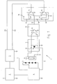
- the signal device 1 comprises a power supply unit 2 for Provision of the power supply, a control unit 3 and a pulse generator 4.
- a pulse generator 4 At the pulse generator 4 are Light emitting diodes 5 connected. For example, here are four LEDs available.
- the pulse generator 4 is connected both to the power supply 2 and connected to the control unit 3. He gets over that Power supply 2 its supply voltage and is over the Control unit 3 controlled.
- a photosensor 6 is connected to a switching stage 7, which a switch, in the present case in the form of the transistor 8, includes.
- the transistor 8 via the line. 9 switched by means of the pulse generator 4, which in turn via the control unit 3 is controlled.
- the transistor 8 could but also directly from the control unit 3 be switched.
- a capacity 10 is also located in the circuit of the Photosensor 6.
- the capacitance smoothes the sensor signal of the Photosensor 6 and prevents u.a. an undesirable DC component in this circuit.
- An amplification unit 11 amplifies by means of a Amplifier 12, the sensor signal of the photosensor 6. Der Output 13 of the amplifier 12 is at the negative input a first comparator 14 and the positive input a second comparator 15 connected.
- a Reference voltage 16 defined by means of a series circuit of three resistors 17, 18, 19 two different ones Potentials 20, 21, which are not yet due to the Sensor occupied input of the comparators 14, 15 are laid.
- the two comparators 14, 15 deliver in this way each one exceeding the potentials 20, 21 defined threshold signal via the signal lines 22, 23 to the control unit 3.
- a device with a circuit according to FIG. 1 is capable of perform a power control of the LED 5, the dependent is the brightness or intensity of the ambient light.
- the ambient light is detected by the photosensor 6 as well via the amplifier unit and the comparators 14, 15 evaluated. In this case, the power control in three stages.
- the LED 5 Without sensor signal from the comparators 14, 15, the LED 5 operated with normal standard performance. When crossing a threshold, the comparator 15 provides a signal whereby in a first stage the achievement over the Control unit 3 and the pulse generator 4 is increased. To Exceeding a second threshold with corresponding Signal via the comparator 14, the control unit. 3 by means of the pulse generator 4, the LED 5 in another operate at a higher power level.
- the switching stage 7 downstream electronic Components can be switched by switching over the transistor 8 of FIG the environment sensor 6 are turned off.
- the LEDs 5 is located.
- an intermittent operation may take place, i. the Amplifier unit 11 and the following electronics will only when the LED 5 is turned off by means of the transistor 8 switched on. This way, regardless of the Emission of the LEDs 5 detects the ambient light and evaluated.
- the device according to FIG. 1 represents a particularly simple one Variant is in the frequency independent of the intensity of the Ambient light detected and dependent on thresholds the Light intensity of the LED controlled in three power levels becomes. Basically is with correspondingly more complex Electronics also a continuous control possible. A such control can also take into account other parameters, such as the frequency of the ambient light, the Time of day, etc .. Furthermore are also several Environmental sensors 6 for detection and evaluation different disturbances or different properties of Disturbances conceivable.
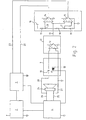
- the device according to FIG. 2 essentially corresponds to FIG aforementioned embodiment, wherein now instead of the LED 5 and the photosensor 6 a bidirectional, electroacoustic transducer 24 is provided.
- This Sound transducer 24 serves as a signal or Sound generator to the desired signal at appropriate Control via the control unit 3 and the pulse generator 4 to produce.
- the transducer 24 is on the above Lines 25, 26 connected to the pulse generator 4.
- the sound transducer 24 operates bidirectionally, i. at the Impact of sound waves is the sound transducer 24 in the Able, an output signal on lines 25, 26 too generate, tapped via the sensor lines 27, 28 and as evaluated in the above embodiment.
- the sound transducer 24 also serves as a sound generator and sound sensor. This is in intermittent operation possible, because on the one hand in sound generation the Sensor electronics is turned off via the transistor 8 and on the other hand, the sound transducer 24 without control over the Pulse generator 4 is available as a sensor.
- the Lines 25, 26 are for this purpose preferably in the phase without Sound generation completed with high impedance.
- the embodiment according to FIG. 2 can also be used as optical Signal device are designed.
- bidirectional Sound transducer 24 are here one or more bidirectional optical elements, for example one or several LEDs used.
- LEDs are LED not only capable, with appropriate current supply Light can radiate, but it can with incident light LED also a current or voltage signal won become. An LED is therefore at the same time as a signal generator and usable as a sensor.
- Essential in the invention is a consideration of Environmental disturbances in the generation of the corresponding signal. Also combinations of acoustic and visual signal generators with appropriate control are conceivable within the scope of the invention.
Landscapes
- Physics & Mathematics (AREA)
- General Physics & Mathematics (AREA)
- Circuit Arrangement For Electric Light Sources In General (AREA)
Abstract
Description
- Figur 1
- ein Blockdiagramm eines erfindungsgemäßen Signalgeräts mit Leuchtmitteln und
- Figur 2
- ein Blockdiagramm eines erfindungsgemäßen Signalgeräts mit Schallquelle.
- 1
- Signalgerät
- 2
- Netzteil
- 3
- Steuereinheit
- 4
- Impulsgenerator
- 5
- Leuchtdioden
- 6
- Fotosensor
- 7
- Schaltstufe
- 8
- Transistor
- 9
- Leitung
- 10
- Kapazität
- 11
- Verstärkungseinheit
- 12
- Verstärker
- 13
- Ausgang
- 14
- Komparator
- 15
- Komparator
- 16
- Referenzspannung
- 17
- Widerstand
- 18
- Widerstand
- 19
- Widerstand
- 20
- Potential
- 21
- Potential
- 22
- Signalleitung
- 23
- Signalleitung
- 24
- Schallwandler
- 25
- Leitung
- 26
- Leitung
- 27
- Sensorleitung
- 28
- Sensorleitung
Claims (13)
- Signalgerät, insbesondere zur Anzeige von Betriebszuständen von Maschinen und Anlagen mit wenigstens zwei verschiedenen Signalgeneratoren für wenigstens zwei unterschiedliche Signale, wobei wenigstens ein Signalgenerator über eine Steuereinheit elektrisch bzw. elektronisch ansteuerbar ist, dadurch gekennzeichnet, dass wenigstens ein Umgebungssensor (6) zur Erfassung einer die Wahrnehmung des Signals beeinträchtigenden Störgröße aus der Umgebung des Signalsgeräts (1) vorhanden ist und die Steuereinheit (3) für eine störgrößenabhängige Signalsteuerung ausgebildet ist.
- Signalgerät nach Anspruch 1, dadurch gekennzeichnet, dass ein intermittierender Betrieb der Signalerzeugung und der Signalerfassung vorgesehen ist.
- Signalgerät nach einem der vorgenannten Ansprüche, dadurch gekennzeichnet, dass das gleiche Bauelement (24) zur Signalerzeugung und zur Signalerfassung vorgesehen ist.
- Signalgerät nach einem der vorgenannten Ansprüche, dadurch gekennzeichnet, dass ein visueller Signalgenerator (5) und ein visueller Umgebungssensor (6) zur Erfassung von Umgebungslicht vorgesehen ist.
- Signalgerät nach einem der vorgenannten Ansprüche, dadurch gekennzeichnet, dass ein akustischer Signalgenerator (24) und ein akustischer Sensor (24) für die Erfassung von Umgebungsschall vorgesehen ist.
- Signalgerät nach einem der vorgenannten Ansprüche, dadurch gekennzeichnet, dass der Umgebungssensor (6, 24) intensitätsempfindlich ist.
- Signalgerät nach einem der vorgenannten Ansprüche, dadurch gekennzeichnet, dass der Umgebungssensor (6, 24) frequenzabhängig und/oder richtungsabhängig ist.
- Signalgerät nach einem der vorgenannten Ansprüche, dadurch gekennzeichnet, dass eine Steuerung der Intensität des Signalgenerators (5, 24) vorgesehen ist.
- Signalgerät nach einem der vorgenannten Ansprüche, dadurch gekennzeichnet, dass eine Steuerung der Frequenz des Signalgenerators (5, 24) vorgesehen ist.
- Signalgerät nach einem der vorgenannten Ansprüche, dadurch gekennzeichnet, dass zwei oder mehrere steuerbare Signalgeneratoren vorgesehen sind.
- Signalgerät nach einem der vorgenannten Ansprüche, dadurch gekennzeichnet, dass zwei oder mehrere Umgebungssensoren zur Erfassung und Auswertung unterschiedlicher Störgrößen vorhanden sind.
- Signalgerät nach einem der vorgenannten Ansprüche, dadurch gekennzeichnet, dass wenigstens ein Signalsensor zur Erfassung von Signaleigenschaften wie der Intensität, der Frequenz, der Richtung usw. des vom Signalgenerators erzeugten Signals vorhanden ist.
- Signalgerät nach einem der vorgenannten Ansprüche, dadurch gekennzeichnet, dass eine Regelung des vom Signalgenerator erzeugten Signals unter Berücksichtigung der Auswertung der vom Signalsensor sowie vom Umgebungssensor erfassten Messwerte vorgesehen ist.
Applications Claiming Priority (4)
| Application Number | Priority Date | Filing Date | Title |
|---|---|---|---|
| DE10354363 | 2003-11-20 | ||
| DE10354363 | 2003-11-20 | ||
| DE10361758A DE10361758B4 (de) | 2003-11-20 | 2003-12-29 | Signalgerät |
| DE10361758 | 2003-12-29 |
Publications (2)
| Publication Number | Publication Date |
|---|---|
| EP1533766A1 true EP1533766A1 (de) | 2005-05-25 |
| EP1533766B1 EP1533766B1 (de) | 2006-06-14 |
Family
ID=34436338
Family Applications (1)
| Application Number | Title | Priority Date | Filing Date |
|---|---|---|---|
| EP20040026044 Expired - Lifetime EP1533766B1 (de) | 2003-11-20 | 2004-11-03 | Signalgerät |
Country Status (2)
| Country | Link |
|---|---|
| EP (1) | EP1533766B1 (de) |
| DE (1) | DE502004000762D1 (de) |
Citations (2)
| Publication number | Priority date | Publication date | Assignee | Title |
|---|---|---|---|---|
| EP0518267A2 (de) * | 1991-06-13 | 1992-12-16 | KONE Elevator GmbH | Verfahren zur automatischen, örtlichen Steuerung der Helligkeit und Lautstärke für Aufzugsignale |
| US5576685A (en) * | 1992-01-29 | 1996-11-19 | Kabushiki Kaisha Kawai Gakki Seisakusho | Sound generation apparatus responsive to environmental conditions for use in a public space |
-
2004
- 2004-11-03 EP EP20040026044 patent/EP1533766B1/de not_active Expired - Lifetime
- 2004-11-03 DE DE200450000762 patent/DE502004000762D1/de not_active Expired - Lifetime
Patent Citations (2)
| Publication number | Priority date | Publication date | Assignee | Title |
|---|---|---|---|---|
| EP0518267A2 (de) * | 1991-06-13 | 1992-12-16 | KONE Elevator GmbH | Verfahren zur automatischen, örtlichen Steuerung der Helligkeit und Lautstärke für Aufzugsignale |
| US5576685A (en) * | 1992-01-29 | 1996-11-19 | Kabushiki Kaisha Kawai Gakki Seisakusho | Sound generation apparatus responsive to environmental conditions for use in a public space |
Also Published As
| Publication number | Publication date |
|---|---|
| DE502004000762D1 (de) | 2006-07-27 |
| EP1533766B1 (de) | 2006-06-14 |
Similar Documents
| Publication | Publication Date | Title |
|---|---|---|
| EP2786596B1 (de) | Verfahren und vorrichtung zur überprüfung einer lautsprecheranordnung | |
| DE2903041C2 (de) | Meldevorrichtung zur Überwachung des Auftretens von zu meldenden Ereignissen | |
| DE2823542A1 (de) | Detektor zum erfassen und anzeigen eines elektrostatischen feldes | |
| DE69733955T2 (de) | Steuersystem für akustischen melder | |
| DE2627119B2 (de) | Fahrzeugalarmanlage | |
| DE112018005238T5 (de) | Schaltung und verfahren zum detektieren eines ausfalls einer led-lampe | |
| DE2137893C3 (de) | Annäherungs-Signalgeber | |
| DE3931038C2 (de) | ||
| EP3719465B1 (de) | Elektrisches installationsmodul | |
| CH691787A5 (de) | Klirrunterdruckung bei Hörgeräten mit AGC. | |
| DE2704565C3 (de) | ||
| EP3123608B1 (de) | Eingangsstufe für eine motorsteuerung sowie motorsteuerung, insbesondere für einen elektromotor | |
| DE10361758B4 (de) | Signalgerät | |
| EP1533766B1 (de) | Signalgerät | |
| EP2553811A1 (de) | Detektionsschaltung und verfahren zum betreiben einer detektionsschaltung | |
| EP2401514B1 (de) | Proportionalregelventil für pneumatische anwendungen | |
| DE3131490C2 (de) | ||
| DE102011055594A1 (de) | Leuchte, insbesondere LED-Scheinwerfer, für ein Kraftfahrzeug. Steuergerät für die Leuchte und Anordnung aus der Leuchte und dem Steuergerät | |
| DE4422308A1 (de) | Automatisches Rottenwarngerät | |
| DE2751917A1 (de) | Elektronische schaltung zur helligkeitssteuerung von leuchtquellen | |
| EP1256815B1 (de) | Abstandswarngerät für Kraftfahrzeuge und Betriebsverfahren | |
| EP1719090B1 (de) | Einrichtung zur detektion von stromgeprägten signalen in sicherheitstechnischen systemen | |
| DE19623481A1 (de) | Automatische Leuchtensteuerungsvorrichtung | |
| EP3253181B1 (de) | Verfahren zur datenkommunikation zwischen einem sende-/empfangsmodul und einem led-modul aufweisend zumindest eine led oder zwischen einem sende-/empfangsmodul und led-modulen in einer reihenschaltung mehrerer led-module, aufweisend jeweils zumindest eine led | |
| DE102014202869A1 (de) | Vorrichtung zur Umfeldsensorik mit verbesserter Dynamikanpassung |
Legal Events
| Date | Code | Title | Description |
|---|---|---|---|
| PUAI | Public reference made under article 153(3) epc to a published international application that has entered the european phase |
Free format text: ORIGINAL CODE: 0009012 |
|
| AK | Designated contracting states |
Kind code of ref document: A1 Designated state(s): AT BE BG CH CY CZ DE DK EE ES FI FR GB GR HU IE IS IT LI LU MC NL PL PT RO SE SI SK TR |
|
| AX | Request for extension of the european patent |
Extension state: AL HR LT LV MK YU |
|
| 17P | Request for examination filed |
Effective date: 20050715 |
|
| GRAP | Despatch of communication of intention to grant a patent |
Free format text: ORIGINAL CODE: EPIDOSNIGR1 |
|
| AKX | Designation fees paid |
Designated state(s): CH DE FR GB IT LI |
|
| GRAS | Grant fee paid |
Free format text: ORIGINAL CODE: EPIDOSNIGR3 |
|
| GRAA | (expected) grant |
Free format text: ORIGINAL CODE: 0009210 |
|
| AK | Designated contracting states |
Kind code of ref document: B1 Designated state(s): CH DE FR GB IT LI |
|
| PG25 | Lapsed in a contracting state [announced via postgrant information from national office to epo] |
Ref country code: IT Free format text: LAPSE BECAUSE OF FAILURE TO SUBMIT A TRANSLATION OF THE DESCRIPTION OR TO PAY THE FEE WITHIN THE PRESCRIBED TIME-LIMIT;WARNING: LAPSES OF ITALIAN PATENTS WITH EFFECTIVE DATE BEFORE 2007 MAY HAVE OCCURRED AT ANY TIME BEFORE 2007. THE CORRECT EFFECTIVE DATE MAY BE DIFFERENT FROM THE ONE RECORDED. Effective date: 20060614 |
|
| REG | Reference to a national code |
Ref country code: GB Ref legal event code: FG4D Free format text: NOT ENGLISH |
|
| REG | Reference to a national code |
Ref country code: CH Ref legal event code: EP |
|
| REF | Corresponds to: |
Ref document number: 502004000762 Country of ref document: DE Date of ref document: 20060727 Kind code of ref document: P |
|
| GBT | Gb: translation of ep patent filed (gb section 77(6)(a)/1977) | ||
| REG | Reference to a national code |
Ref country code: CH Ref legal event code: NV Representative=s name: KELLER & PARTNER PATENTANWAELTE AG |
|
| ET | Fr: translation filed | ||
| PLBE | No opposition filed within time limit |
Free format text: ORIGINAL CODE: 0009261 |
|
| STAA | Information on the status of an ep patent application or granted ep patent |
Free format text: STATUS: NO OPPOSITION FILED WITHIN TIME LIMIT |
|
| 26N | No opposition filed |
Effective date: 20070315 |
|
| REG | Reference to a national code |
Ref country code: CH Ref legal event code: PFA Owner name: WERMA HOLDING GMBH + CO. KG Free format text: WERMA SIGNALTECHNIK GMBH & CO.KG#DUERBHEIMER STRASSE 15#78604 RIETHEIM-WEILHEIM (DE) -TRANSFER TO- WERMA HOLDING GMBH + CO. KG#DUERBHEIMER STRASSE 15#78604 RIETHEIM-WEILHEIM (DE) |
|
| REG | Reference to a national code |
Ref country code: FR Ref legal event code: CD |
|
| REG | Reference to a national code |
Ref country code: CH Ref legal event code: PCAR Free format text: NEW ADDRESS: EIGERSTRASSE 2 POSTFACH, 3000 BERN 14 (CH) |
|
| REG | Reference to a national code |
Ref country code: FR Ref legal event code: PLFP Year of fee payment: 12 |
|
| REG | Reference to a national code |
Ref country code: FR Ref legal event code: PLFP Year of fee payment: 13 |
|
| REG | Reference to a national code |
Ref country code: FR Ref legal event code: PLFP Year of fee payment: 14 |
|
| REG | Reference to a national code |
Ref country code: CH Ref legal event code: PFA Owner name: WERMA HOLDING GMBH + CO. KG, DE Free format text: FORMER OWNER: WERMA HOLDING GMBH + CO. KG, DE |
|
| PGFP | Annual fee paid to national office [announced via postgrant information from national office to epo] |
Ref country code: GB Payment date: 20231123 Year of fee payment: 20 |
|
| PGFP | Annual fee paid to national office [announced via postgrant information from national office to epo] |
Ref country code: IT Payment date: 20231130 Year of fee payment: 20 Ref country code: FR Payment date: 20231124 Year of fee payment: 20 Ref country code: DE Payment date: 20231120 Year of fee payment: 20 Ref country code: CH Payment date: 20231202 Year of fee payment: 20 |
|
| REG | Reference to a national code |
Ref country code: DE Ref legal event code: R071 Ref document number: 502004000762 Country of ref document: DE |
|
| REG | Reference to a national code |
Ref country code: CH Ref legal event code: PL |
|
| REG | Reference to a national code |
Ref country code: GB Ref legal event code: PE20 Expiry date: 20241102 |
|
| PG25 | Lapsed in a contracting state [announced via postgrant information from national office to epo] |
Ref country code: GB Free format text: LAPSE BECAUSE OF EXPIRATION OF PROTECTION Effective date: 20241102 |
|
| PG25 | Lapsed in a contracting state [announced via postgrant information from national office to epo] |
Ref country code: GB Free format text: LAPSE BECAUSE OF EXPIRATION OF PROTECTION Effective date: 20241102 |