EP1533591B1 - Electronic apparatus, signal compensation device, and signal compensation method - Google Patents
Electronic apparatus, signal compensation device, and signal compensation method Download PDFInfo
- Publication number
- EP1533591B1 EP1533591B1 EP03791251.6A EP03791251A EP1533591B1 EP 1533591 B1 EP1533591 B1 EP 1533591B1 EP 03791251 A EP03791251 A EP 03791251A EP 1533591 B1 EP1533591 B1 EP 1533591B1
- Authority
- EP
- European Patent Office
- Prior art keywords
- signal
- angular velocity
- velocity sensor
- output
- stationary state
- Prior art date
- Legal status (The legal status is an assumption and is not a legal conclusion. Google has not performed a legal analysis and makes no representation as to the accuracy of the status listed.)
- Expired - Fee Related
Links
Images


Classifications
-
- G—PHYSICS
- G01—MEASURING; TESTING
- G01C—MEASURING DISTANCES, LEVELS OR BEARINGS; SURVEYING; NAVIGATION; GYROSCOPIC INSTRUMENTS; PHOTOGRAMMETRY OR VIDEOGRAMMETRY
- G01C19/00—Gyroscopes; Turn-sensitive devices using vibrating masses; Turn-sensitive devices without moving masses; Measuring angular rate using gyroscopic effects
- G01C19/56—Turn-sensitive devices using vibrating masses, e.g. vibratory angular rate sensors based on Coriolis forces
-
- G—PHYSICS
- G01—MEASURING; TESTING
- G01P—MEASURING LINEAR OR ANGULAR SPEED, ACCELERATION, DECELERATION, OR SHOCK; INDICATING PRESENCE, ABSENCE, OR DIRECTION, OF MOVEMENT
- G01P13/00—Indicating or recording presence, absence, or direction, of movement
-
- G—PHYSICS
- G01—MEASURING; TESTING
- G01P—MEASURING LINEAR OR ANGULAR SPEED, ACCELERATION, DECELERATION, OR SHOCK; INDICATING PRESENCE, ABSENCE, OR DIRECTION, OF MOVEMENT
- G01P21/00—Testing or calibrating of apparatus or devices covered by the preceding groups
Definitions
- the present invention relates to a signal compensation device and a signal compensation method used for such a device.
- Japanese Unexamined Patent Application Publication No. 2002-7027 discloses a technique for scrolling an image displayed on a display unit in response to movement of a housing of a portable device such as a portable terminal or a cellular phone. For example, when a user who holds such a device in his/her hand moves the device to the right, the image is also scrolled to the right.
- An angular velocity sensor is used as equipment for sensing movement of the housing. For example, a reference value of the angular velocity sensor is determined, and the change from the reference value is output as an electrical signal. Then, a screen is scrolled according to the output result.
- an angular velocity sensor for use in such a device changes the reference value upon a change in the ambient temperature, that is, a so-called temperature drift occurs.
- the temperature drift is output as low-frequency variations, and affects image scrolling. This can cause, for example, a failure that the image displayed on a display unit is automatically scrolled even when a user does not move the device or the screen is scrolled in the direction different from the direction in which the user moves the device.
- the present invention has been made in view of such situations, and it is an object of the present invention to provide a signal compensation device, and a signal compensation method that prevent a failure caused by a temperature drift of an angular velocity sensor.
- US 6,361,507 B1 describes an inertial orientation tracker having gradual automatic drift compensation for tracking human head and other similar sized body.
- JP 10 124245 describes a pen-type input device.
- JP 10122865 describes a detecting and measuring method for rotational angular velocity and gyro for execution of the method.
- the human arm moves around a pivot point at the elbow or shoulder.
- the motion of a user who moves a housing in a space is close to a spherical motion.
- it is only required to detect the velocity of spherical motion, i.e., the angular velocity, of the arm.
- acceleration ⁇ velocityV d t
- an acceleration sensor can determine the velocity by integrating the data obtained at a given time width t. Once the velocity of a moving object for a constant period of time is determined, the moving distance is further determined by integrating the value of the determined velocity. The amount of scrolling is therefore determined.
- the acceleration sensor is more susceptible to the acceleration of gravity than the angular velocity sensor, and this can cause an error.
- the angular velocity sensor is used as means for detecting the amount of movement.
- the angular velocity sensor is primarily used to detect vibration caused by the shaking of the hand holding electronic equipment.
- the vibration caused by shaking exhibits short-wavelength high-frequency variations.
- a high-pass filter or the like is used to remove the low-frequency variations to output only the high-frequency variations.
- the temperature drift outputs low-frequency variations, and such variations are thus removed. Therefore, in detecting the vibration caused by shaking, the failure issue due to the temperature drift does not occur.
- the detection operation of the angular velocity sensor according to the present invention corresponds to the user operation of moving the device while visually monitoring the display unit, and exhibits low-frequency variations of long wavelength.
- the operation of moving the device is correlated to low-frequency variations due to the temperature drift.
- comparison to the output of the angular velocity sensor when the device is in a stationary state allows for extraction of the value of the temperature drift. Based on this value, the output of the angular velocity sensor can be compensated for.
- the output of the angular velocity sensor of the device in the stationary state at a given temperature is stored in advance.
- the output of the angular velocity sensor of the device in the stationary state at a different temperature is detected.
- the detected output is compared to the previously stored output of the angular velocity sensor, and the difference in the reference value that changes due to the temperature drift is extracted.
- the output of the angular velocity sensor in a moving state of the device equals the sum of the output as a result of the movement and the output as a result of the temperature drift.
- the extracted difference in the reference value is equivalent to the output as a result of the temperature drift.
- the angular velocity sensor is not sufficiently sensitive to linear motion.
- the acceleration sensor is capable of detecting the acceleration of movement during linear motion. Due to the suitability for detection of the absolute movement, the acceleration sensor is able to detect linear movement of the device and is also able to detect the stationary state in which the device does not move. Thus, no additional sensor is required for detecting the stationary state, and the complexity of a processing system does not increase, resulting in efficient processing.
- the angular velocity sensor is suitable for detection of the relative movement, and is thus able to detect the amount of hand and arm movement.
- the acceleration sensor is mainly used, the response is low and the accumulated error in the integration is large, compared to a case where the angular velocity sensor is mainly used.
- the acceleration sensor is used as an auxiliary sensor to the angular velocity sensor.
- a signal compensation device includes an angular velocity sensor that outputs a first signal in accordance with a rotational angular velocity, means for storing in advance a second signal normally output by the angular velocity sensor that is in a stationary state, means for detecting a stationary state, means for extracting the difference between the first signal and the second signal when the stationary state is detected, and means for compensating for the first signal based on the extracted difference signal.
- a signal compensation device includes an angular velocity sensor that outputs a first signal in accordance with a rotational angular velocity, means for storing in advance data of a second signal normally output by the angular velocity sensor that is in a stationary state, a button, means for extracting the difference between the first signal and the second signal when the button is pressed, and means for compensating for the first signal based on the extracted difference signal.
- a signal compensation method includes a step of detecting a stationary state, a step of reading a first signal output from an angular velocity sensor, a step of reading data of a second signal from a storage medium, the data of the second signal being normally output by the angular velocity sensor that is in a stationary state, a step of extracting the difference between the read first signal and second signal when the stationary state is detected, and a step of compensating for the first signal based on the extracted difference signal.
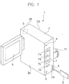
- Fig. 1 is a perspective view of an electronic device.
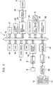
- Fig. 2 is a block diagram showing hardware configuration of the display device.
- a display device 1 has a housing 2 that is sized, for example, so as to be held by a user in his/her hand.
- a speaker 4, a microphone 5, and a reset button 10 are disposed on a front surface 2a of the housing 2.
- An operation unit 7 having an OK button 7a, an undo button 7b, and a camera capture button 7c, and a mounting unit 9 to which, for example, a stick-type storage medium 8 is removably inserted are further disposed on the front surface 2a.
- a camera 3 is disposed on a back surface 2b of the housing 2.
- the camera 3 is, for example, a CCD camera.
- a display unit 6 is disposed on a side surface 2c of the housing 2.
- the display unit 6 is, for example, a color liquid crystal display device.
- a handle 11 is disposed on a side surface 2d of the housing 2.
- the display device 1 is configured such that a CPU 15, a ROM 16, a flash memory 17, a RAM 18, a storage medium interface 19, a sensor interface 20, and other various interfaces including, for example, a TTY (Tele Typewriter) 21, an NIC (network interface card), for example, an Ethernet (registered trademark) board 22, an image processing unit 23, a Visca interface 24, a VGA board 25, and an audio & video interface 26 are connected to a main bus 14.
- the CPU 15 collectively controls the overall display device 1.
- the ROM 16 is used to store programs necessary for the operation of the CPU 15.
- the necessary programs include, for example, a program for a changeover switch, as described below.
- the flash memory 17 is used to store necessary data.
- the necessary data includes output data of an angular velocity sensor at a given temperature, as described below.
- the RAM 18 is used as a work space for processing.
- the storage medium interface 19 is connected with the mounting unit 9. Data is communicated with the storage medium 8 inserted in the mounting unit 9.
- the sensor interface 20 is connected in parallel to an angular velocity sensor 12 and an acceleration sensor 13 via an A/D converter 27 and a low-pass filter 29.
- the TTY (Tele Typewriter) 21 is connected with the various buttons in the operation area described above.
- the Ethernet board 22 allows for connection to the Ethernet. This allows for connection to, for example, a server via the Ethernet, and further allows for connection to the Internet via this server.
- the image processing unit 23 is connected with a camera interface 28.
- the camera interface 28 is connected with the CCD camera 3 described above.
- An image connected by the CCD camera 3 can be captured in the display device 1, and can also be displayed on the display unit 6.
- the Visca interface 24 is connected with an external personal computer, and so forth. Various control operations of the display device 1 can be performed via this interface.
- the VGA board 25 is connected with a liquid crystal display device serving as the display unit 6.
- the audio & video interface 26 is connected with audio and video equipment. Via the audio & video interface 26, a signal from such audio and video equipment can be captured in the display device 1, or, conversely, an audio signal or a video signal can be output.
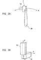
- Figs. 3A and 3B illustrate the angular velocity sensor.
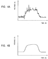
- Figs. 4A and 4B are graphs that plot the results output from the angular velocity sensor.
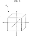
- Fig. 5 illustrates the acceleration sensor.
- Fig. 6 shows the position at which the angular velocity sensor and the acceleration sensor are to be mounted.
- the angular velocity sensor 12 is a device that detects the rotational angular velocity of the display device 1, and that outputs the result as a voltage.
- the angular velocity sensor 12 is shaped into, for example, a rectangular cylinder whose length parallel to the movement detection direction is 1 cm and whose lengths perpendicular thereto are 0.5 cm and 0.3 cm.
- the motion of human arm is close to a spherical motion around the elbow or shoulder.
- the display device 1 moves in the direction ⁇ along a sphere around a pivot point at, for example, an elbow 28.
- the velocity of the arm movement it is only required to detect the velocity of spherical motion, i.e., the angular velocity, of the arm.
- acceleration ⁇ velocityV d t
- an acceleration detecting device for example, an acceleration sensor or the like, described below, can determine the velocity by integrating the data obtained at a given time width t. Once the movement velocity of the display device 1 for a constant period of time is determined, the moving distance is further determined by integrating the value of the determined velocity. The amount of scrolling on the screen is therefore determined.
- the angular velocity sensor 12 is used as means for detecting the amount of movement.
- the angular velocity sensor 12 is primarily used to detect vibration caused by the shaking of the hand holding electronic equipment.
- the vibration caused by shaking exhibits short-wavelength high-frequency variations.
- a high-pass filter or the like is used to remove the low-frequency variations to output only the high-frequency variations.
- the temperature drift outputs low-frequency variations, and such variations are thus removed. Therefore, in detecting the vibration caused by shaking, the failure issue due to the temperature drift does not occur.
- the detection operation of the angular velocity sensor 12 corresponds to the user operation of moving the display device 1 while visually monitoring the displaying unit 6, and exhibits low-frequency variations of long wavelength.
- the operation of moving the display device 1 is correlated to low-frequency variations due to the temperature drift.
- the output of the angular velocity sensor 12 of the display device 1 in the stationary state at a given temperature is stored in advance. For example, the output of the angular velocity sensor 12 of the display device 1 in the stationary state at a different temperature is detected. The detected output is compared to the previously stored output of the angular velocity sensor 12, and the difference in the reference value that changes due to the temperature drift is extracted.
- the output of the angular velocity sensor 12 in a moving state of the device equals the sum of the output as a result of the movement and the output as a result of the temperature drift.
- the extracted difference in the reference value is equivalent to the output as a result of the temperature drift.
- the angular velocity sensor 12 detects the rotational angular velocity in the direction ⁇ , and outputs the result as a voltage.
- the output is represented by a change from a reference voltage.
- a reference voltage For example, when a user whose arm is 45 cm long rotates the display device 1 at a rotational angle of 5° for 0.2 seconds, the displacement voltage of the angular velocity sensor 12 is about 10 mV.
- the reference voltage of the angular velocity sensor 12 is about 1.5 V.
- the output angular velocity value passes through, for example, a low-pass filter (not shown) to remove the high-frequency components.
- the output with the high-frequency components removed undergoes time integration using numerical integration by the CPU 15 to determine the displacement component of the display device 1.
- the angular velocity sensor 12 detects the angular velocity in only one rotation direction.
- the angular velocity sensor 12 in order to detect the motion across more than one rotation direction, for example, two directions shown in Fig. 3B , i.e., the directions ⁇ and ⁇ , the angular velocity sensor 12 must be positioned in conformity to each rotational axis.
- the angular velocity sensor 12 outputs the ⁇ -direction component and the ⁇ -direction component of the angular velocity applied to the display device 1.
- the output results pass through the low-pass filter 29, and then undergo time integration using numerical integration by the CPU 15 to determine the displacement components of the display device 1, respectively.
- the result of detection by the angular velocity sensor 12 is shown in, for example, Fig. 4A .
- the y-axis designates the output voltage (V) of the angular velocity sensor 12
- the x-axis designates time (second).
- This output waveform includes a component related to the movement of the display device, which is detected by the angular velocity sensor 12, a component related to vibration caused by shaking or the like, and a component related to the temperature drift of the angular velocity sensor 12.
- the result whose high-frequency component, which is a shaking component, has been removed by the low-pass filter 29 is shown in Fig. 4B .
- This waveform includes only the component related to the movement of the display device, which is detected by the angular velocity sensor 12, and the component related to the temperature drift of the angular velocity sensor 12.
- the display device 1 causes the image to be scrolled according to the output voltage value of the angular velocity sensor 12.
- the output voltage exhibits the low-frequency variations, and therefore a small change of the voltage due to shaking or the like shown in Fig. 4A , i.e., high-frequency variations, need not be detected. If such a small change is processed as it is, the image can blur during scrolling, thus making a user very difficult to view. This is the reason why the unwanted high-frequency variations are removed using the low-pass filter 29.
- the acceleration sensor 13 is a device that detects the acceleration in two or three axial directions when a user moves the display device 1 in a space while holding it in his/her hand, and that outputs the result as a voltage.
- Fig. 5 shows that the acceleration sensor is used as, for example, a sensor for detecting the acceleration in three axial directions.
- the vertical component, horizontal component, and forward-backward component of the acceleration applied to the display device 1 are detected, and time integration is performed for each component to determine the velocity component and the displacement component.
- the display device 1 When the display device 1 is in the stationary state, no acceleration is applied to the display device 1, and the output voltage of the acceleration sensor 13 becomes the voltage under no acceleration. In other words, the displacement of the output voltage of the acceleration sensor 13 per unit of time is zero. Thus, by determining that the output from the acceleration sensor 13 becomes the voltage under no acceleration (the displacement of the output voltage per unit of time is zero), the stationary state of the display device 1 can be detected. Thus, no additional sensor is required for detecting the stationary state, and the complexity of a processing system does not increase, resulting in efficient processing.
- the calculation results of the angular velocity sensor 12 and the acceleration sensor 13 are used for compensation for the temperature drift and are also used for image scrolling, as described below.
- the display unit 6 includes a rear cover 6a, a frame 6b, a front cover 6c, a liquid crystal device 6d, the angular velocity sensor 12, and the acceleration sensor 13.
- the angular velocity sensor 12 includes three angular velocity sensors, that is, an angular velocity sensor 12a for detecting the movement in the X-direction, an angular velocity sensor 12b for detecting the movement in the Y-direction, and an angular velocity sensor 12c for detecting the movement in the Z-direction.
- the angular velocity sensors 12a and 12b are bonded to the inside of the rear cover 6a.
- the angular velocity sensor 12c is bonded to the outside of the frame 6b.
- the angular velocity sensor 12 is shaped into a rectangular cylinder whose longitudinal length is 1 cm.
- the angular velocity sensor 12c is disposed so that the longitudinal direction thereof is in parallel to the thickness direction of the display unit 6. If the angular velocity sensor 12c is disposed inside the display unit 6, the thickness of the display unit 6 can increase. The angular velocity sensor 12c is thus disposed outside the frame 6b.
- a single acceleration sensor 13 is disposed.
- the single acceleration sensor 13 is sufficient to detect the movement in the X, Y, and Z axial directions.
- the acceleration sensor 13 is preferably close to the angular velocity sensor 12a and the angular velocity sensor 12b, but may be spaced apart therefrom.
- the angular velocity sensor 12 and the acceleration sensor 13 are connected with the CPU 15 via the low-pass filter 29 and the A/D converter 27.
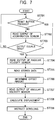
- Fig. 7 shows processing steps of the CPU 15 until the screen is scrolled after the display device 1 moves.
- Fig. 8 shows the temperature drift of the angular velocity sensor 12, where the y-axis designates the voltage (V) and the x-axis designates the temperature (°C).
- the CPU 15 determines whether or not the reset button 10 has been pressed by a user (step 701). If the reset button 10 has been pressed, then, the process proceeds to step 704 with steps 702 and 703 omitted. If the reset button 10 has not been pressed, the output voltage of the acceleration sensor 13 is read (step 702). Then, the acceleration sensor 12 detects the acceleration in order to determine whether or not the display device 1 is in the stationary state. If the output of the acceleration sensor 13 is zero, then the process proceeds to the next step, and, if the output is not zero, the processing of steps 701 and 2 is repeated (step 703).
- the CPU 15 reads the output voltage of the angular velocity sensor 12 (step 704). Then, the CPU 15 reads the output voltage of the angular velocity sensor 12 in the stationary state at a given temperature, which has been stored in the flash memory 17 (step 705), and the value obtained by subtracting the value of the output voltage of the angular velocity sensor 12, which is read in step 705, from the value of the output voltage of the angular velocity sensor 12, which is read in step 704, is extracted as the amount of offset due to the temperature drift (step 706).
- step 707 the value output from the angular velocity sensor 12 when the user moves the display device 1 is read (step 707).
- the amount of offset extracted in step 706 By subtracting the amount of offset extracted in step 706 from this output value, the change of the voltage caused by the temperature drift is removed, and the displacement as a result of the movement is thus determined (step 708).
- An image scrolling instruction based on this value is sent (step 709).
- the angular velocity sensor 12 exhibits an output indicated by a curve ⁇ shown in Fig. 8 when the temperature changes in the stationary state.
- a curve ⁇ represents the output value when the angular velocity sensor 12 is moved a certain amount.
- the curve ⁇ is shifted in parallel from the curve ⁇ in the forward direction of the voltage axis. For example, an output value ⁇ at 20°C is stored in the flash memory 17 or the like.
- the case at 40°C is taken as example.
- the output of the angular velocity sensor 12 in the stationary state at 40°C is ⁇ 1.
- the calculation of step 706 is performed.
- the value ⁇ stored in the flash memory 17 is read, and the difference between ⁇ 1 and ⁇ is determined to extract the amount of offset due to the temperature drift.
- the output value at 40°C when the user moves the display device 1 a certain amount is ⁇ 1.
- the calculation of step 707 is performed, and ⁇ is added to ⁇ 1 to determine the compensated output.
- the compensated output ⁇ is constant irrespective of the temperature.
- the value of ⁇ stored in the flash memory 17 is subtracted from ⁇ , thereby determining ( ⁇ 1 - ⁇ 1). This is the displacement caused by the actual movement. Therefore, the image is scrolled based on the value of ( ⁇ 1 - ⁇ 1).
- the difference between the output voltage at a given temperature when the display device 1 is moved a certain amount (the output voltage in the curve ⁇ 1 at a given temperature) and the output voltage in the curve ⁇ 1 at this temperature is determined to detect the displacement as a result of only the movement of the display device 1.
- the curve ⁇ 1 may be stored by default at the shipping time of the display device 1.
- Fig. 9 is a flowchart showing this operation.
- the display device 1 shows the initial screen on the display unit 6 upon power on (step 901).
- Fig. 10 is an illustration of an example of the initial screen.
- On the screen of the display unit 6 shown in Fig. 10 for example, "menu”, “restaurant”, “department store”, “cinema”, “food shop”, “map”, “picture”, “text input”, and so on are shown.
- a currently selectable item on the screen is highlighted (indicated by reference numeral 37 shown in Fig. 10 ), and the highlighted item 37 is selected when the OK button 7a is pressed.
- Such highlight is, for example, fixed on the screen.
- the screen is scrolled to move the items in the manner described above, thereby selecting the item 37 to be highlighted.
- step 1102 When the display device 1 is moved up and down (step 1102), in response to this movement, the display device 1 scrolls, for example, up and down the screen of the display unit 6 (step 1103).
- a desired item for example, "picture”
- the OK button 7a is pressed (step 904), the selection screen for "picture” is displayed on the display unit 6 (step 905).
- the display device 1 scrolls the screen of the display unit 6, for example, up, down, right, and left (step 907).
- the display device 1 shows an amount-presentation screen 38 on the display unit 6 (step 909).
- the screen 38 contains, for example, an amount display section 39 for displaying the fee of the content, a purchase confirmation button 40, and multiple-content purchase button 41.
- the multiple-content purchase button 41 is pressed, the user returns to the initial screen to add the content to be further purchased.
- the largest image of the four images A1, A2, B1, and B2 on the display screen may be highlighted, and an appropriate highlight screen may be selected by scrolling, thereby selecting content using the OK button 7a.
- the selected content is provided to the display device 1, for example, from a server via the Internet (step 910) .
- the display device 1 displays content 44 on the display unit 6 in the manner shown in, for example, Fig. 12 (step 911), and stores the content 44 in the storage medium (step 912) .
- the user moves the display device 1 as desired, and is thus allowed to view an image 45 of the content 44 displayed on the display unit 6, while scrolling the image 45.
- Fig. 13 illustrates an example image that is to be displayed on the display unit 6 when "map" is selected from the items on the initial screen shown in Fig. 10 .
- the display device 1 is moved (step 906) to scroll the screen, for example, up, down, right, and left (step 907), and a predetermined image on the map is selected (step 908), for example, more detailed map in this area is shown as the selected content on the display unit 6, and is stored in the storage medium 8.
- a user can press the reset button 10 to compensate for the temperature drift of the angular velocity sensor 12. This prevents a failure.
- the angular velocity sensor detects the amount of movement of the device. This allows for detection of the amount of movement of the device without an influence of the acceleration of gravity.
- the present invention is not limited to the foregoing embodiment.
- the content is an image, by way of example; however, the content may be music, etc.
- a stop button (not shown) may be disposed for preventing image scrolling when a user does not desire to scroll the image displayed on the display unit 6 while he/she moves the display device 1.
- an angular velocity sensor is used to detect the amount of movement of a device, and an acceleration sensor is used to detect a stationary state of the device. This allows for detection of the amount of movement of the device without an influence of the acceleration of gravity. Moreover, this prevents a failure caused by the temperature drift of the angular velocity sensor.
Description
- The present invention relates to a signal compensation device and a signal compensation method used for such a device.
- Japanese Unexamined Patent Application Publication No.
2002-7027 - However, an angular velocity sensor for use in such a device changes the reference value upon a change in the ambient temperature, that is, a so-called temperature drift occurs. The temperature drift is output as low-frequency variations, and affects image scrolling. This can cause, for example, a failure that the image displayed on a display unit is automatically scrolled even when a user does not move the device or the screen is scrolled in the direction different from the direction in which the user moves the device.
- The present invention has been made in view of such situations, and it is an object of the present invention to provide a signal compensation device, and a signal compensation method that prevent a failure caused by a temperature drift of an angular velocity sensor.
-
US 6,361,507 B1 describes an inertial orientation tracker having gradual automatic drift compensation for tracking human head and other similar sized body. -
JP 10 124245 -
JP 10122865 - Aspects of the invention are set out in the appended claims. In order to overcome the foregoing problem, the present invention provides a signal compensation device according to
claim claim - The human arm moves around a pivot point at the elbow or shoulder. The motion of a user who moves a housing in a space is close to a spherical motion. In order to detect the velocity of the arm movement, it is only required to detect the velocity of spherical motion, i.e., the angular velocity, of the arm.
- In general, the relation between acceleration and velocity is given by Eq. 1 as follows:

- As is found from Eq. 1, an acceleration sensor can determine the velocity by integrating the data obtained at a given time width t. Once the velocity of a moving object for a constant period of time is determined, the moving distance is further determined by integrating the value of the determined velocity. The amount of scrolling is therefore determined.
- However, a double integral by means of time needs to be calculated in order to determine the moving distance of the moving object from the acceleration, possibly resulting in response delay or accumulated error. Moreover, the acceleration sensor is more susceptible to the acceleration of gravity than the angular velocity sensor, and this can cause an error. As described above, it is only required to detect the angular velocity in order to detect the arm movement. In the present invention, therefore, the angular velocity sensor is used as means for detecting the amount of movement.
- The amount of scrolling is given by Eq. 2 using the angular velocity:

- The angular velocity sensor is primarily used to detect vibration caused by the shaking of the hand holding electronic equipment. The vibration caused by shaking exhibits short-wavelength high-frequency variations. When the vibration caused by shaking is to be detected, for example, a high-pass filter or the like is used to remove the low-frequency variations to output only the high-frequency variations. The temperature drift outputs low-frequency variations, and such variations are thus removed. Therefore, in detecting the vibration caused by shaking, the failure issue due to the temperature drift does not occur.
- The detection operation of the angular velocity sensor according to the present invention corresponds to the user operation of moving the device while visually monitoring the display unit, and exhibits low-frequency variations of long wavelength. The operation of moving the device is correlated to low-frequency variations due to the temperature drift.
- According to the present invention, comparison to the output of the angular velocity sensor when the device is in a stationary state allows for extraction of the value of the temperature drift. Based on this value, the output of the angular velocity sensor can be compensated for.
- In the present invention, the output of the angular velocity sensor of the device in the stationary state at a given temperature is stored in advance. For example, the output of the angular velocity sensor of the device in the stationary state at a different temperature is detected. The detected output is compared to the previously stored output of the angular velocity sensor, and the difference in the reference value that changes due to the temperature drift is extracted. The output of the angular velocity sensor in a moving state of the device equals the sum of the output as a result of the movement and the output as a result of the temperature drift. The extracted difference in the reference value is equivalent to the output as a result of the temperature drift. Therefore, by removing the extracted difference in the reference value from the output of the angular velocity sensor in the moving state of the device, only the output as a result of the movement can be determined. Where the angular velocity for the drift is indicated by Δωk, the amount of scrolling after the correction is given by Eq. 3:

- Therefore, a failure that the image displayed on the display unit is automatically scrolled due to the temperature drift of the angular velocity sensor does not occur.
- Generally, the angular velocity sensor is not sufficiently sensitive to linear motion. On the other hand, the acceleration sensor is capable of detecting the acceleration of movement during linear motion. Due to the suitability for detection of the absolute movement, the acceleration sensor is able to detect linear movement of the device and is also able to detect the stationary state in which the device does not move. Thus, no additional sensor is required for detecting the stationary state, and the complexity of a processing system does not increase, resulting in efficient processing.
- On the other hand, the angular velocity sensor is suitable for detection of the relative movement, and is thus able to detect the amount of hand and arm movement. In a case where the acceleration sensor is mainly used, the response is low and the accumulated error in the integration is large, compared to a case where the angular velocity sensor is mainly used. However, only the linear motion, which is not sufficiently detected by the angular velocity sensor, is detected by the acceleration sensor, thus preventing such a low response and low scrolling response. In the present invention, the acceleration sensor is used as an auxiliary sensor to the angular velocity sensor. Thus, sufficient sensitivity to linear motion is achievable, and movement of the device is more reliably detectable.
- Specifically, a signal compensation device includes an angular velocity sensor that outputs a first signal in accordance with a rotational angular velocity, means for storing in advance a second signal normally output by the angular velocity sensor that is in a stationary state, means for detecting a stationary state, means for extracting the difference between the first signal and the second signal when the stationary state is detected, and means for compensating for the first signal based on the extracted difference signal.
- A signal compensation device includes an angular velocity sensor that outputs a first signal in accordance with a rotational angular velocity, means for storing in advance data of a second signal normally output by the angular velocity sensor that is in a stationary state, a button, means for extracting the difference between the first signal and the second signal when the button is pressed, and means for compensating for the first signal based on the extracted difference signal.
- A signal compensation method includes a step of detecting a stationary state, a step of reading a first signal output from an angular velocity sensor, a step of reading data of a second signal from a storage medium, the data of the second signal being normally output by the angular velocity sensor that is in a stationary state, a step of extracting the difference between the read first signal and second signal when the stationary state is detected, and a step of compensating for the first signal based on the extracted difference signal.
-
-
Fig. 1 is a perspective view showing the appearance of a display device according to an embodiment of the present invention. -
Fig. 2 is a block diagram showing hardware configuration of the display device according to the embodiment. -
Figs. 3A and 3B are perspective views of an angular velocity sensor for use in the display device according to the embodiment. -
Figs. 4A and 4B are output graphs of the angular velocity sensor for use in the display device according to the embodiment. -
Fig. 5 is a perspective view of an acceleration sensor for use in the display device according to the embodiment. -
Fig. 6 is a perspective view showing a portion of the display device according to the embodiment. -
Fig. 7 is a flowchart showing the operation of temperature-drift compensation. -
Fig. 8 is a diagram showing the principle of temperature-drift compensation. -
Fig. 9 is a flowchart showing the operation of the display device. -
Fig. 10 is a view showing an example initial screen displayed on the display device. -
Fig. 11 is a view showing an example amount-presentation screen displayed on the display device. -
Fig. 12 is a view showing an example content image displayed on the display device. -
Fig. 13 is a view showing another example content image displayed on the display device. - An embodiment of the present invention will be described hereinbelow with reference to the drawings.
- An electronic device will be described with reference to
Figs. 1 and2 in the context of a display device, by way of example. -
Fig. 1 is a perspective view of an electronic device.Fig. 2 is a block diagram showing hardware configuration of the display device. - As shown in
Fig. 1 , adisplay device 1 has ahousing 2 that is sized, for example, so as to be held by a user in his/her hand. - A speaker 4, a
microphone 5, and areset button 10 are disposed on afront surface 2a of thehousing 2. Anoperation unit 7 having an OK button 7a, an undo button 7b, and acamera capture button 7c, and a mounting unit 9 to which, for example, a stick-type storage medium 8 is removably inserted are further disposed on thefront surface 2a. - A
camera 3 is disposed on aback surface 2b of thehousing 2. Thecamera 3 is, for example, a CCD camera. - A
display unit 6 is disposed on aside surface 2c of thehousing 2. Thedisplay unit 6 is, for example, a color liquid crystal display device. Ahandle 11 is disposed on aside surface 2d of thehousing 2. - As shown in
Fig. 2 , thedisplay device 1 is configured such that aCPU 15, aROM 16, aflash memory 17, aRAM 18, astorage medium interface 19, asensor interface 20, and other various interfaces including, for example, a TTY (Tele Typewriter) 21, an NIC (network interface card), for example, an Ethernet (registered trademark)board 22, animage processing unit 23, aVisca interface 24, aVGA board 25, and an audio &video interface 26 are connected to amain bus 14. TheCPU 15 collectively controls theoverall display device 1. TheROM 16 is used to store programs necessary for the operation of theCPU 15. The necessary programs include, for example, a program for a changeover switch, as described below. Theflash memory 17 is used to store necessary data. The necessary data includes output data of an angular velocity sensor at a given temperature, as described below. TheRAM 18 is used as a work space for processing. - The
storage medium interface 19 is connected with the mounting unit 9. Data is communicated with thestorage medium 8 inserted in the mounting unit 9. - The
sensor interface 20 is connected in parallel to anangular velocity sensor 12 and anacceleration sensor 13 via an A/D converter 27 and a low-pass filter 29. - The TTY (Tele Typewriter) 21 is connected with the various buttons in the operation area described above.
- The
Ethernet board 22 allows for connection to the Ethernet. This allows for connection to, for example, a server via the Ethernet, and further allows for connection to the Internet via this server. - The
image processing unit 23 is connected with acamera interface 28. Thecamera interface 28 is connected with theCCD camera 3 described above. An image connected by theCCD camera 3 can be captured in thedisplay device 1, and can also be displayed on thedisplay unit 6. - The
Visca interface 24 is connected with an external personal computer, and so forth. Various control operations of thedisplay device 1 can be performed via this interface. - The
VGA board 25 is connected with a liquid crystal display device serving as thedisplay unit 6. - The audio &
video interface 26 is connected with audio and video equipment. Via the audio &video interface 26, a signal from such audio and video equipment can be captured in thedisplay device 1, or, conversely, an audio signal or a video signal can be output. - The angular velocity sensor and acceleration sensor disposed in the
display device 1 will now be described with reference toFigs. 3A through 6 . -
Figs. 3A and 3B illustrate the angular velocity sensor.Figs. 4A and 4B are graphs that plot the results output from the angular velocity sensor.Fig. 5 illustrates the acceleration sensor.Fig. 6 shows the position at which the angular velocity sensor and the acceleration sensor are to be mounted. - The
angular velocity sensor 12 is a device that detects the rotational angular velocity of thedisplay device 1, and that outputs the result as a voltage. Theangular velocity sensor 12 is shaped into, for example, a rectangular cylinder whose length parallel to the movement detection direction is 1 cm and whose lengths perpendicular thereto are 0.5 cm and 0.3 cm. - The motion of human arm is close to a spherical motion around the elbow or shoulder. As shown in
Fig. 3A , when a user moves thedisplay device 1, thedisplay device 1 moves in the direction α along a sphere around a pivot point at, for example, anelbow 28. In order to detect the velocity of the arm movement, it is only required to detect the velocity of spherical motion, i.e., the angular velocity, of the arm. In general, the relation between acceleration and velocity is given by Eq. 1 as follows:
- As is found from Eq. 1, an acceleration detecting device, for example, an acceleration sensor or the like, described below, can determine the velocity by integrating the data obtained at a given time width t. Once the movement velocity of the
display device 1 for a constant period of time is determined, the moving distance is further determined by integrating the value of the determined velocity. The amount of scrolling on the screen is therefore determined. - However, a double integral by means of time needs to be calculated in order to determine the moving distance of the
display device 1 from the acceleration, possibly resulting in response delay or accumulated error. As described above, it is only required to detect the angular velocity in order to detect the arm movement. In the present invention, therefore, theangular velocity sensor 12 is used as means for detecting the amount of movement. - The amount of scrolling on the screen is given by Eq. 2 using the angular velocity:

- The
angular velocity sensor 12 is primarily used to detect vibration caused by the shaking of the hand holding electronic equipment. The vibration caused by shaking exhibits short-wavelength high-frequency variations. When the vibration caused by shaking is to be detected, for example, a high-pass filter or the like is used to remove the low-frequency variations to output only the high-frequency variations. The temperature drift outputs low-frequency variations, and such variations are thus removed. Therefore, in detecting the vibration caused by shaking, the failure issue due to the temperature drift does not occur. - The detection operation of the
angular velocity sensor 12 corresponds to the user operation of moving thedisplay device 1 while visually monitoring the displayingunit 6, and exhibits low-frequency variations of long wavelength. The operation of moving thedisplay device 1 is correlated to low-frequency variations due to the temperature drift. - The output of the
angular velocity sensor 12 of thedisplay device 1 in the stationary state at a given temperature is stored in advance. For example, the output of theangular velocity sensor 12 of thedisplay device 1 in the stationary state at a different temperature is detected. The detected output is compared to the previously stored output of theangular velocity sensor 12, and the difference in the reference value that changes due to the temperature drift is extracted. The output of theangular velocity sensor 12 in a moving state of the device equals the sum of the output as a result of the movement and the output as a result of the temperature drift. The extracted difference in the reference value is equivalent to the output as a result of the temperature drift. Therefore, by removing the extracted difference in the reference value from the output of theangular velocity sensor 12 in the moving state of thedisplay device 1, only the output as a result of the movement can be determined. Where the angular velocity for the drift is indicated by Δωk, the amount of scrolling after the correction is given by Eq. 3 as follows:
- The
angular velocity sensor 12 detects the rotational angular velocity in the direction α, and outputs the result as a voltage. The output is represented by a change from a reference voltage. For example, when a user whose arm is 45 cm long rotates thedisplay device 1 at a rotational angle of 5° for 0.2 seconds, the displacement voltage of theangular velocity sensor 12 is about 10 mV. The reference voltage of theangular velocity sensor 12 is about 1.5 V. The output angular velocity value passes through, for example, a low-pass filter (not shown) to remove the high-frequency components. The output with the high-frequency components removed undergoes time integration using numerical integration by theCPU 15 to determine the displacement component of thedisplay device 1. - The
angular velocity sensor 12 detects the angular velocity in only one rotation direction. Thus, in order to detect the motion across more than one rotation direction, for example, two directions shown inFig. 3B , i.e., the directions α and β, theangular velocity sensor 12 must be positioned in conformity to each rotational axis. In this case, theangular velocity sensor 12 outputs the α-direction component and the β-direction component of the angular velocity applied to thedisplay device 1. The output results pass through the low-pass filter 29, and then undergo time integration using numerical integration by theCPU 15 to determine the displacement components of thedisplay device 1, respectively. - The result of detection by the
angular velocity sensor 12 is shown in, for example,Fig. 4A . In the graph shown inFig. 4A , the y-axis designates the output voltage (V) of theangular velocity sensor 12, and the x-axis designates time (second). This output waveform includes a component related to the movement of the display device, which is detected by theangular velocity sensor 12, a component related to vibration caused by shaking or the like, and a component related to the temperature drift of theangular velocity sensor 12. The result whose high-frequency component, which is a shaking component, has been removed by the low-pass filter 29 is shown inFig. 4B . This waveform includes only the component related to the movement of the display device, which is detected by theangular velocity sensor 12, and the component related to the temperature drift of theangular velocity sensor 12. Thedisplay device 1 causes the image to be scrolled according to the output voltage value of theangular velocity sensor 12. The output voltage exhibits the low-frequency variations, and therefore a small change of the voltage due to shaking or the like shown inFig. 4A , i.e., high-frequency variations, need not be detected. If such a small change is processed as it is, the image can blur during scrolling, thus making a user very difficult to view. This is the reason why the unwanted high-frequency variations are removed using the low-pass filter 29. - The
acceleration sensor 13 is a device that detects the acceleration in two or three axial directions when a user moves thedisplay device 1 in a space while holding it in his/her hand, and that outputs the result as a voltage. -
Fig. 5 shows that the acceleration sensor is used as, for example, a sensor for detecting the acceleration in three axial directions. The vertical component, horizontal component, and forward-backward component of the acceleration applied to thedisplay device 1 are detected, and time integration is performed for each component to determine the velocity component and the displacement component. - When the
display device 1 is in the stationary state, no acceleration is applied to thedisplay device 1, and the output voltage of theacceleration sensor 13 becomes the voltage under no acceleration. In other words, the displacement of the output voltage of theacceleration sensor 13 per unit of time is zero. Thus, by determining that the output from theacceleration sensor 13 becomes the voltage under no acceleration (the displacement of the output voltage per unit of time is zero), the stationary state of thedisplay device 1 can be detected. Thus, no additional sensor is required for detecting the stationary state, and the complexity of a processing system does not increase, resulting in efficient processing. - The calculation results of the
angular velocity sensor 12 and theacceleration sensor 13 are used for compensation for the temperature drift and are also used for image scrolling, as described below. - As shown in
Fig. 6 , thedisplay unit 6 includes arear cover 6a, aframe 6b, afront cover 6c, a liquid crystal device 6d, theangular velocity sensor 12, and theacceleration sensor 13. Theangular velocity sensor 12 includes three angular velocity sensors, that is, an angular velocity sensor 12a for detecting the movement in the X-direction, an angular velocity sensor 12b for detecting the movement in the Y-direction, and an angular velocity sensor 12c for detecting the movement in the Z-direction. The angular velocity sensors 12a and 12b are bonded to the inside of therear cover 6a. The angular velocity sensor 12c is bonded to the outside of theframe 6b. Theangular velocity sensor 12 is shaped into a rectangular cylinder whose longitudinal length is 1 cm. The angular velocity sensor 12c is disposed so that the longitudinal direction thereof is in parallel to the thickness direction of thedisplay unit 6. If the angular velocity sensor 12c is disposed inside thedisplay unit 6, the thickness of thedisplay unit 6 can increase. The angular velocity sensor 12c is thus disposed outside theframe 6b. - A
single acceleration sensor 13 is disposed. Thesingle acceleration sensor 13 is sufficient to detect the movement in the X, Y, and Z axial directions. Theacceleration sensor 13 is preferably close to the angular velocity sensor 12a and the angular velocity sensor 12b, but may be spaced apart therefrom. Theangular velocity sensor 12 and theacceleration sensor 13 are connected with theCPU 15 via the low-pass filter 29 and the A/D converter 27. - A process for scrolling the screen will now be described with reference to
Figs. 7 and8 . -
Fig. 7 shows processing steps of theCPU 15 until the screen is scrolled after thedisplay device 1 moves.Fig. 8 shows the temperature drift of theangular velocity sensor 12, where the y-axis designates the voltage (V) and the x-axis designates the temperature (°C). - As shown in
Fig. 7 , first, theCPU 15 determines whether or not thereset button 10 has been pressed by a user (step 701). If thereset button 10 has been pressed, then, the process proceeds to step 704 with steps 702 and 703 omitted. If thereset button 10 has not been pressed, the output voltage of theacceleration sensor 13 is read (step 702). Then, theacceleration sensor 12 detects the acceleration in order to determine whether or not thedisplay device 1 is in the stationary state. If the output of theacceleration sensor 13 is zero, then the process proceeds to the next step, and, if the output is not zero, the processing ofsteps 701 and 2 is repeated (step 703). - If the reset button has been pressed by the user, or if the displacement of the output voltage of the
acceleration sensor 13 is zero, theCPU 15 reads the output voltage of the angular velocity sensor 12 (step 704). Then, theCPU 15 reads the output voltage of theangular velocity sensor 12 in the stationary state at a given temperature, which has been stored in the flash memory 17 (step 705), and the value obtained by subtracting the value of the output voltage of theangular velocity sensor 12, which is read in step 705, from the value of the output voltage of theangular velocity sensor 12, which is read in step 704, is extracted as the amount of offset due to the temperature drift (step 706). - Then, for example, the value output from the
angular velocity sensor 12 when the user moves thedisplay device 1 is read (step 707). By subtracting the amount of offset extracted in step 706 from this output value, the change of the voltage caused by the temperature drift is removed, and the displacement as a result of the movement is thus determined (step 708). An image scrolling instruction based on this value is sent (step 709). - With such processing, a failure due to the temperature drift is overcome.
- The principle of the processing steps described above will be described in the context of movement in one direction, by way of example.
- The
angular velocity sensor 12 exhibits an output indicated by a curve β shown inFig. 8 when the temperature changes in the stationary state. A curve α represents the output value when theangular velocity sensor 12 is moved a certain amount. The curve α is shifted in parallel from the curve β in the forward direction of the voltage axis. For example, an output value θ at 20°C is stored in theflash memory 17 or the like. - For example, the case at 40°C is taken as example. The output of the
angular velocity sensor 12 in the stationary state at 40°C is β1. The calculation of step 706 is performed. The value θ stored in theflash memory 17 is read, and the difference between β1 and θ is determined to extract the amount of offset due to the temperature drift. Where the amount of offset is indicated by Δ, the following equation is given:
- The output value at 40°C when the user moves the display device 1 a certain amount is α1. The calculation of step 707 is performed, and Δ is added to α1 to determine the compensated output. Where the compensated output is indicated by ω, the following equation is given:

flash memory 17 is subtracted from ω, thereby determining (α1 - β1). This is the displacement caused by the actual movement. Therefore, the image is scrolled based on the value of (α1 - β1). - That is, actually, once the
display device 1 stores the curve β1 for the stationary state, when the user actually uses thedisplay device 1, the difference between the output voltage at a given temperature when thedisplay device 1 is moved a certain amount (the output voltage in the curve α1 at a given temperature) and the output voltage in the curve β1 at this temperature is determined to detect the displacement as a result of only the movement of thedisplay device 1. The curve α1 may be stored by default at the shipping time of thedisplay device 1. - The operation for purchasing content using the
display device 1 will now be described. -
Fig. 9 is a flowchart showing this operation. - The
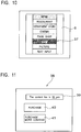
display device 1 shows the initial screen on thedisplay unit 6 upon power on (step 901).Fig. 10 is an illustration of an example of the initial screen. On the screen of thedisplay unit 6 shown inFig. 10 , for example, "menu", "restaurant", "department store", "cinema", "food shop", "map", "picture", "text input", and so on are shown. Although not shown on this screen, other items underlie them, and the hidden items are to be viewed by moving down thedisplay device 1 to scroll down the screen. A currently selectable item on the screen is highlighted (indicated byreference numeral 37 shown inFig. 10 ), and the highlighteditem 37 is selected when the OK button 7a is pressed. Such highlight is, for example, fixed on the screen. The screen is scrolled to move the items in the manner described above, thereby selecting theitem 37 to be highlighted. - When the
display device 1 is moved up and down (step 1102), in response to this movement, thedisplay device 1 scrolls, for example, up and down the screen of the display unit 6 (step 1103). When a desired item, for example, "picture", is highlighted by the user and the OK button 7a is pressed (step 904), the selection screen for "picture" is displayed on the display unit 6 (step 905). - Also, when the
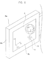
display device 1 is moved up, down, right, and left (step 906), in response to this movement, thedisplay device 1 scrolls the screen of thedisplay unit 6, for example, up, down, right, and left (step 907). When the user selects one image from four divided content images available A1, A2, B1, and B2 (step 908), as shown inFig. 11 , thedisplay device 1 shows an amount-presentation screen 38 on the display unit 6 (step 909). Thescreen 38 contains, for example, anamount display section 39 for displaying the fee of the content, apurchase confirmation button 40, and multiple-content purchase button 41. When the multiple-content purchase button 41 is pressed, the user returns to the initial screen to add the content to be further purchased. - In the selection described above, for example, the largest image of the four images A1, A2, B1, and B2 on the display screen may be highlighted, and an appropriate highlight screen may be selected by scrolling, thereby selecting content using the OK button 7a.
- When the user selects content upon presentation of the content fee, the selected content is provided to the
display device 1, for example, from a server via the Internet (step 910) . - The
display device 1displays content 44 on thedisplay unit 6 in the manner shown in, for example,Fig. 12 (step 911), and stores thecontent 44 in the storage medium (step 912) . - The user moves the
display device 1 as desired, and is thus allowed to view animage 45 of thecontent 44 displayed on thedisplay unit 6, while scrolling theimage 45. -
Fig. 13 illustrates an example image that is to be displayed on thedisplay unit 6 when "map" is selected from the items on the initial screen shown inFig. 10 . In this state, when thedisplay device 1 is moved (step 906) to scroll the screen, for example, up, down, right, and left (step 907), and a predetermined image on the map is selected (step 908), for example, more detailed map in this area is shown as the selected content on thedisplay unit 6, and is stored in thestorage medium 8. - During this operation, the failure issue that an image is scrolled due to the temperature drift of the
angular velocity sensor 12 even when thedisplay device 1 is in the stationary state does not occur. - Also, a user can press the
reset button 10 to compensate for the temperature drift of theangular velocity sensor 12. This prevents a failure. - The angular velocity sensor detects the amount of movement of the device. This allows for detection of the amount of movement of the device without an influence of the acceleration of gravity.
- The present invention is not limited to the foregoing embodiment.
- In the foregoing embodiment, the content is an image, by way of example; however, the content may be music, etc.
- For example, a stop button (not shown) may be disposed for preventing image scrolling when a user does not desire to scroll the image displayed on the
display unit 6 while he/she moves thedisplay device 1. - While the embodiment has been described in the context of a display device, by way of example, the present invention is applicable to any device using an angular velocity sensor.
- As described above, according to the present invention, an angular velocity sensor is used to detect the amount of movement of a device, and an acceleration sensor is used to detect a stationary state of the device. This allows for detection of the amount of movement of the device without an influence of the acceleration of gravity. Moreover, this prevents a failure caused by the temperature drift of the angular velocity sensor.
Claims (6)
- A signal compensation device comprising:an angular velocity sensor (12) that outputs a first signal (α1, β1) in accordance with a rotational angular velocity;means (17) for storing in advance a second signal (θ) output by said angular velocity sensor (12) when in a stationary state at a given temperature;an acceleration sensor (13) for detecting a stationary state;a processor (15) configured forreading the first signal (β1) output by said angular velocity sensor (12) when the stationary state is detected;extracting the difference (Δ) between the first signal (β1) read when the stationary state is detected and the second signal (θ);reading the first signal (α1) output by said angular velocity sensor (12) when in a non-stationary state; andcompensating for the first signal (α1) read when in the non-stationary state based on the extracted difference signal (Δ).
- A signal compensation device comprising:an angular velocity sensor (12) that outputs a first signal (α1, β1) in accordance with a rotational angular velocity;means (17) for storing in advance data of a second signal (θ) output by said angular velocity sensor (12) when in a stationary state at a given temperature;a button (10) configured to indicate, when pressed, a stationary state;a processor (15) configured forreading the first signal (β1) output by said angular velocity sensor (12) when the button (10) is pressed;extracting the difference (Δ) between the first signal (β1) read when the button is pressed and the second signal (θ);reading the first signal (α1) output by said angular velocity sensor (12) when in a non-stationary state; andcompensating for the first signal (α1) read when in the non-stationary state based on the extracted difference signal (Δ).
- An electronic device comprising:a signal compensation device according to claim 1;and a display unit (6) that scrolls and displays an image based on the compensated signal.
- An electronic device comprising:a signal compensation device according to claim 2; anda display unit (6) that scrolls and displays an image based on the compensated signal.
- A signal compensation method comprising:a step (ST702, ST703) of detecting a stationary state based on the output of an acceleration sensor (13);a step (ST704) of reading a first signal (β1) output from an angular velocity sensor (12) when the stationary state is detected;a step (ST705) of reading data of a second signal (θ) from a storage device (17), the data of the second signal being output by said angular velocity sensor (12) when the angular velocity sensor is in a stationary state at a given temperature;a step (ST706) of extracting the difference (Δ) between the first signal (β1) read when the stationary state is detected and the second signal (θ);a step (ST707) of reading the first signal (α1) output from said angular velocity sensor (12) when in a non-stationary state; anda step (ST708) of compensating for the first signal (α1) read when in the non-stationary state based on the extracted difference signal (Δ).
- A signal compensation method comprising:a step (ST701) of detecting a button (10) being pressed, the button being configured to indicate, when pressed, a stationary state;a step (ST704) of reading a first signal (β1) output from an angular velocity sensor (12) when the button (10) is pressed;a step (ST705) of reading data of a second signal (θ) from a storage device (17), the data of the second signal being output by said angular velocity sensor (12) when the angular velocity sensor is in a stationary state at a given temperature;a step (ST706) of extracting the difference (Δ) between the first signal (β1) read when the button (10) is pressed and the second signal (θ);a step (ST707) of reading the first signal (α1) output from said angular velocity sensor (12) when in a non-stationary state;a step (ST708) of compensating for the first signal (α1) read when in the non-stationary state based on the extracted difference signal (Δ).
Applications Claiming Priority (5)
| Application Number | Priority Date | Filing Date | Title |
|---|---|---|---|
| JP2002249795 | 2002-08-28 | ||
| JP2002249795 | 2002-08-28 | ||
| JP2002274156 | 2002-09-19 | ||
| JP2002274156A JP4482269B2 (en) | 2002-08-28 | 2002-09-19 | Electronic device apparatus, signal compensation apparatus, and signal compensation method |
| PCT/JP2003/010633 WO2004020945A1 (en) | 2002-08-28 | 2003-08-22 | Electronic apparatus, signal compensation device, and signal compensation method |
Publications (3)
| Publication Number | Publication Date |
|---|---|
| EP1533591A1 EP1533591A1 (en) | 2005-05-25 |
| EP1533591A4 EP1533591A4 (en) | 2009-01-07 |
| EP1533591B1 true EP1533591B1 (en) | 2019-05-01 |
Family
ID=31980508
Family Applications (1)
| Application Number | Title | Priority Date | Filing Date |
|---|---|---|---|
| EP03791251.6A Expired - Fee Related EP1533591B1 (en) | 2002-08-28 | 2003-08-22 | Electronic apparatus, signal compensation device, and signal compensation method |
Country Status (6)
| Country | Link |
|---|---|
| US (2) | US7225101B2 (en) |
| EP (1) | EP1533591B1 (en) |
| JP (1) | JP4482269B2 (en) |
| KR (1) | KR101028202B1 (en) |
| CN (1) | CN100392352C (en) |
| WO (1) | WO2004020945A1 (en) |
Families Citing this family (49)
| Publication number | Priority date | Publication date | Assignee | Title |
|---|---|---|---|---|
| US7749089B1 (en) | 1999-02-26 | 2010-07-06 | Creative Kingdoms, Llc | Multi-media interactive play system |
| US6761637B2 (en) | 2000-02-22 | 2004-07-13 | Creative Kingdoms, Llc | Method of game play using RFID tracking device |
| US7878905B2 (en) | 2000-02-22 | 2011-02-01 | Creative Kingdoms, Llc | Multi-layered interactive play experience |
| US7445550B2 (en) | 2000-02-22 | 2008-11-04 | Creative Kingdoms, Llc | Magical wand and interactive play experience |
| US7066781B2 (en) | 2000-10-20 | 2006-06-27 | Denise Chapman Weston | Children's toy with wireless tag/transponder |
| US6967566B2 (en) | 2002-04-05 | 2005-11-22 | Creative Kingdoms, Llc | Live-action interactive adventure game |
| US20070066396A1 (en) | 2002-04-05 | 2007-03-22 | Denise Chapman Weston | Retail methods for providing an interactive product to a consumer |
| US9446319B2 (en) | 2003-03-25 | 2016-09-20 | Mq Gaming, Llc | Interactive gaming toy |
| JP4779299B2 (en) * | 2004-01-27 | 2011-09-28 | ソニー株式会社 | Display device, display control method, recording medium, and program |
| US7927216B2 (en) * | 2005-09-15 | 2011-04-19 | Nintendo Co., Ltd. | Video game system with wireless modular handheld controller |
| JP4805633B2 (en) | 2005-08-22 | 2011-11-02 | 任天堂株式会社 | Game operation device |
| US8313379B2 (en) | 2005-08-22 | 2012-11-20 | Nintendo Co., Ltd. | Video game system with wireless modular handheld controller |
| JP4262726B2 (en) | 2005-08-24 | 2009-05-13 | 任天堂株式会社 | Game controller and game system |
| US8870655B2 (en) | 2005-08-24 | 2014-10-28 | Nintendo Co., Ltd. | Wireless game controllers |
| US8308563B2 (en) | 2005-08-30 | 2012-11-13 | Nintendo Co., Ltd. | Game system and storage medium having game program stored thereon |
| US8157651B2 (en) | 2005-09-12 | 2012-04-17 | Nintendo Co., Ltd. | Information processing program |
| JP2008003002A (en) * | 2006-06-23 | 2008-01-10 | Asahi Kasei Electronics Co Ltd | Angular velocity measuring device |
| JP4509988B2 (en) | 2006-09-21 | 2010-07-21 | 株式会社ソニー・コンピュータエンタテインメント | Operation device control apparatus, operation device control method, program, and operation device |
| JP2009207009A (en) * | 2008-02-28 | 2009-09-10 | Sharp Corp | Mobile information terminal |
| JP5173854B2 (en) * | 2008-04-21 | 2013-04-03 | 株式会社豊田中央研究所 | Sensor drift estimation device |
| JP4626671B2 (en) * | 2008-04-24 | 2011-02-09 | ソニー株式会社 | Input device and control system |
| JP2010015535A (en) * | 2008-06-02 | 2010-01-21 | Sony Corp | Input device, control system, handheld device, and calibration method |
| DE102008052485A1 (en) | 2008-10-21 | 2010-04-22 | Volkswagen Ag | Method and device for displaying list-ordered information |
| JP5532865B2 (en) | 2008-12-04 | 2014-06-25 | セイコーエプソン株式会社 | Data processing apparatus and data processing system |
| JP5023111B2 (en) * | 2009-07-28 | 2012-09-12 | 日本電信電話株式会社 | Information processing apparatus, input information determination method, input information determination program, and recording medium recording the input information determination program |
| CN101729665B (en) * | 2009-12-11 | 2013-10-02 | 惠州Tcl移动通信有限公司 | Camera cellphone with tremble prevention function and tremble prevention method in photographing process thereof |
| JP5454133B2 (en) | 2009-12-25 | 2014-03-26 | 富士通株式会社 | Detection information correction device, portable device, detection information correction method, and computer program |
| US8913009B2 (en) | 2010-02-03 | 2014-12-16 | Nintendo Co., Ltd. | Spatially-correlated multi-display human-machine interface |
| US8814686B2 (en) | 2010-02-03 | 2014-08-26 | Nintendo Co., Ltd. | Display device, game system, and game method |
| US8961305B2 (en) | 2010-02-03 | 2015-02-24 | Nintendo Co., Ltd. | Game system, controller device and game method |
| US8339364B2 (en) | 2010-02-03 | 2012-12-25 | Nintendo Co., Ltd. | Spatially-correlated multi-display human-machine interface |
| CN102338634A (en) * | 2010-07-23 | 2012-02-01 | 鸿富锦精密工业(深圳)有限公司 | Mobile electronic device having vibration compensation function and vibration compensation method thereof |
| JP6243586B2 (en) | 2010-08-06 | 2017-12-06 | 任天堂株式会社 | GAME SYSTEM, GAME DEVICE, GAME PROGRAM, AND GAME PROCESSING METHOD |
| US10150033B2 (en) | 2010-08-20 | 2018-12-11 | Nintendo Co., Ltd. | Position calculation system, position calculation device, storage medium storing position calculation program, and position calculation method |
| JP5840385B2 (en) | 2010-08-30 | 2016-01-06 | 任天堂株式会社 | GAME SYSTEM, GAME DEVICE, GAME PROGRAM, AND GAME PROCESSING METHOD |
| JP5840386B2 (en) | 2010-08-30 | 2016-01-06 | 任天堂株式会社 | GAME SYSTEM, GAME DEVICE, GAME PROGRAM, AND GAME PROCESSING METHOD |
| CN101943958B (en) * | 2010-09-29 | 2012-03-07 | 宇龙计算机通信科技(深圳)有限公司 | Method for avoiding faulty operation of track ball and terminal equipment |
| KR101492310B1 (en) | 2010-11-01 | 2015-02-11 | 닌텐도가부시키가이샤 | Operating apparatus and information processing apparatus |
| JP5689014B2 (en) | 2011-04-07 | 2015-03-25 | 任天堂株式会社 | Input system, information processing apparatus, information processing program, and three-dimensional position calculation method |
| CN102230806B (en) * | 2011-04-26 | 2012-11-28 | 中国科学院软件研究所 | Temperature drift compensation method for gyroscope |
| CN102323450B (en) * | 2011-05-19 | 2012-10-24 | 中国科学院测量与地球物理研究所 | Satellite-borne accelerometer data calibrating method based on dual-satellite adjacent energy difference principle |
| CN103336725A (en) * | 2012-12-03 | 2013-10-02 | 顾红波 | System and method for selecting measuring basis correction dynamic state intelligently |
| CN103076639B (en) * | 2012-12-28 | 2015-05-13 | 中国科学院测量与地球物理研究所 | Method for inverting earth gravity field of residual inter-star velocity |
| CN103091721B (en) * | 2013-01-10 | 2015-03-25 | 中国科学院测量与地球物理研究所 | Satellite joint inversion earth gravitational field method using different orbit inclination angles |
| CN103091723B (en) * | 2013-02-06 | 2015-05-13 | 中国科学院测量与地球物理研究所 | Method of reducing influences of gravity satellite centroid adjustment errors to earth gravitational field accuracy |
| JP6337540B2 (en) * | 2014-03-18 | 2018-06-06 | リコーイメージング株式会社 | Temperature compensation device for sensor output |
| US20160095539A1 (en) * | 2014-10-02 | 2016-04-07 | Zikto | Smart band, body balance measuring method of the smart band and computer-readable recording medium comprising program for performing the same |
| JP2018189413A (en) | 2017-04-28 | 2018-11-29 | セイコーエプソン株式会社 | Inertia sensor element control device, inertia sensor, electronic apparatus, moving body and temperature compensation information update method for inertial sensor element control device |
| US11119112B2 (en) * | 2017-08-02 | 2021-09-14 | Samsung Electronics Co., Ltd. | Method for compensating gyroscope drift on an electronic device |
Family Cites Families (23)
| Publication number | Priority date | Publication date | Assignee | Title |
|---|---|---|---|---|
| JPH0694734A (en) | 1992-03-23 | 1994-04-08 | Taya Eng Kk | Drift cancel system and apparatus for angular velocity detecting sensor |
| JPH0666568A (en) * | 1992-08-19 | 1994-03-08 | Sumitomo Electric Ind Ltd | Angular velocity detector, orientation detector and position detector |
| JPH0728591A (en) | 1993-05-13 | 1995-01-31 | Toshiba Corp | Space manipulation mouse system and space operation pattern input method |
| JPH0744315A (en) | 1993-05-21 | 1995-02-14 | Sony Corp | Input device |
| US5645077A (en) * | 1994-06-16 | 1997-07-08 | Massachusetts Institute Of Technology | Inertial orientation tracker apparatus having automatic drift compensation for tracking human head and other similarly sized body |
| JPH0821732A (en) | 1994-07-05 | 1996-01-23 | Data Tec:Kk | Attitude, azimuth, and position measuring apparatus |
| JPH09282086A (en) | 1996-04-16 | 1997-10-31 | Mitsumi Electric Co Ltd | Position information input device |
| JP3560418B2 (en) | 1996-07-15 | 2004-09-02 | 株式会社リコー | Pen-type input device |
| JPH10124245A (en) * | 1996-10-18 | 1998-05-15 | Ricoh Co Ltd | Pen-type input device |
| JPH10122865A (en) * | 1996-10-22 | 1998-05-15 | Japan Aviation Electron Ind Ltd | Detecting and measuring method for rotational angular velocity and gyro for execution of the method |
| JP3776206B2 (en) | 1997-05-07 | 2006-05-17 | 株式会社リコー | Pen-type input device |
| JP3712835B2 (en) | 1997-06-13 | 2005-11-02 | 株式会社リコー | Pen-type input device |
| CN1206110A (en) * | 1997-07-14 | 1999-01-27 | 利顿系统有限公司 | Signal processing system for inertial sensor |
| JPH1144539A (en) | 1997-07-24 | 1999-02-16 | Murata Mfg Co Ltd | Signal processor for inertia sensor |
| US5953683A (en) * | 1997-10-09 | 1999-09-14 | Ascension Technology Corporation | Sourceless orientation sensor |
| JP3780673B2 (en) * | 1997-12-11 | 2006-05-31 | 株式会社日本自動車部品総合研究所 | Angular velocity sensor |
| JPH11345078A (en) | 1998-06-01 | 1999-12-14 | Brother Ind Ltd | Selection and input device for data |
| JP2000065576A (en) | 1998-08-21 | 2000-03-03 | Olympus Optical Co Ltd | Graphic display device |
| JP2000221040A (en) | 1999-02-03 | 2000-08-11 | Murata Mfg Co Ltd | Oscillation gyro |
| JP2000258162A (en) * | 1999-03-04 | 2000-09-22 | Alps Electric Co Ltd | Temperature compensator piezoelectric oscillator |
| JP2001100908A (en) | 1999-09-28 | 2001-04-13 | Fujitsu Ltd | Pen tip trace generating method, pen type input device, and pen mounting unit |
| JP2001153745A (en) * | 1999-11-30 | 2001-06-08 | Hokuriku Electric Ind Co Ltd | Temperature conpensation method and device for sensor output |
| JP2002007027A (en) * | 2000-06-27 | 2002-01-11 | Masanori Idesawa | Image information display device |
-
2002
- 2002-09-19 JP JP2002274156A patent/JP4482269B2/en not_active Expired - Fee Related
-
2003
- 2003-08-22 US US10/493,403 patent/US7225101B2/en not_active Expired - Lifetime
- 2003-08-22 KR KR1020047005603A patent/KR101028202B1/en active IP Right Grant
- 2003-08-22 CN CNB038014211A patent/CN100392352C/en not_active Expired - Fee Related
- 2003-08-22 WO PCT/JP2003/010633 patent/WO2004020945A1/en active Application Filing
- 2003-08-22 EP EP03791251.6A patent/EP1533591B1/en not_active Expired - Fee Related
-
2009
- 2009-05-29 US US12/455,319 patent/USRE43657E1/en not_active Expired - Lifetime
Non-Patent Citations (1)
| Title |
|---|
| None * |
Also Published As
| Publication number | Publication date |
|---|---|
| KR20050042206A (en) | 2005-05-06 |
| EP1533591A1 (en) | 2005-05-25 |
| JP4482269B2 (en) | 2010-06-16 |
| CN100392352C (en) | 2008-06-04 |
| EP1533591A4 (en) | 2009-01-07 |
| WO2004020945A1 (en) | 2004-03-11 |
| USRE43657E1 (en) | 2012-09-11 |
| CN1578899A (en) | 2005-02-09 |
| KR101028202B1 (en) | 2011-04-11 |
| US7225101B2 (en) | 2007-05-29 |
| JP2004145378A (en) | 2004-05-20 |
| US20050071118A1 (en) | 2005-03-31 |
Similar Documents
| Publication | Publication Date | Title |
|---|---|---|
| EP1533591B1 (en) | Electronic apparatus, signal compensation device, and signal compensation method | |
| US8351910B2 (en) | Method and apparatus for determining a user input from inertial sensors | |
| US8922487B2 (en) | Switching between a first operational mode and a second operational mode using a natural motion gesture | |
| EP3407157B1 (en) | Computing system implementing an algorithm for fusing data from inertial sensors, and method | |
| US20090207138A1 (en) | Selecting a layout | |
| JP6098874B2 (en) | Imaging apparatus and image processing apparatus | |
| KR100667853B1 (en) | Apparatus and method for scrolling screen in portable device and recording medium storing program for performing the method thereof | |
| US20090089705A1 (en) | Virtual object navigation | |
| JP4730464B2 (en) | Electronic device apparatus, signal compensation apparatus, and signal compensation method | |
| JP2008135075A (en) | Electronic apparatus, spatial displacement computing device, and spatial displacement computation method | |
| CN110180185B (en) | Time delay measurement method, device, system and storage medium | |
| EP1533685A1 (en) | Handheld device for navigating and displaying data | |
| US20210247884A1 (en) | Display method and display device in portable terminal | |
| JP2019200801A (en) | Terminal device, electronic apparatus, display method, and program | |
| JP2004102736A (en) | Electronic equipment | |
| JP2004102738A (en) | Electronic equipment |
Legal Events
| Date | Code | Title | Description |
|---|---|---|---|
| PUAI | Public reference made under article 153(3) epc to a published international application that has entered the european phase |
Free format text: ORIGINAL CODE: 0009012 |
|
| 17P | Request for examination filed |
Effective date: 20040414 |
|
| AK | Designated contracting states |
Kind code of ref document: A1 Designated state(s): AT BE BG CH CY CZ DE DK EE ES FI FR GB GR HU IE IT LI LU MC NL PT RO SE SI SK TR |
|
| RBV | Designated contracting states (corrected) |
Designated state(s): DE FR GB |
|
| A4 | Supplementary search report drawn up and despatched |
Effective date: 20081209 |
|
| 17Q | First examination report despatched |
Effective date: 20100715 |
|
| RIC1 | Information provided on ipc code assigned before grant |
Ipc: G01C 19/00 19680901AFI20180910BHEP Ipc: G01P 21/00 19680901ALI20180910BHEP |
|
| GRAP | Despatch of communication of intention to grant a patent |
Free format text: ORIGINAL CODE: EPIDOSNIGR1 |
|
| INTG | Intention to grant announced |
Effective date: 20181113 |
|
| RIC1 | Information provided on ipc code assigned before grant |
Ipc: G01C 19/00 20130101AFI20180910BHEP Ipc: G01P 21/00 20060101ALI20180910BHEP |
|
| GRAS | Grant fee paid |
Free format text: ORIGINAL CODE: EPIDOSNIGR3 |
|
| GRAA | (expected) grant |
Free format text: ORIGINAL CODE: 0009210 |
|
| AK | Designated contracting states |
Kind code of ref document: B1 Designated state(s): DE FR GB |
|
| REG | Reference to a national code |
Ref country code: GB Ref legal event code: FG4D |
|
| REG | Reference to a national code |
Ref country code: DE Ref legal event code: R096 Ref document number: 60351982 Country of ref document: DE |
|
| PGFP | Annual fee paid to national office [announced via postgrant information from national office to epo] |
Ref country code: FR Payment date: 20190822 Year of fee payment: 17 Ref country code: DE Payment date: 20190822 Year of fee payment: 17 |
|
| PGFP | Annual fee paid to national office [announced via postgrant information from national office to epo] |
Ref country code: GB Payment date: 20190821 Year of fee payment: 17 |
|
| REG | Reference to a national code |
Ref country code: DE Ref legal event code: R097 Ref document number: 60351982 Country of ref document: DE |
|
| PLBE | No opposition filed within time limit |
Free format text: ORIGINAL CODE: 0009261 |
|
| STAA | Information on the status of an ep patent application or granted ep patent |
Free format text: STATUS: NO OPPOSITION FILED WITHIN TIME LIMIT |
|
| 26N | No opposition filed |
Effective date: 20200204 |
|
| REG | Reference to a national code |
Ref country code: DE Ref legal event code: R119 Ref document number: 60351982 Country of ref document: DE |
|
| GBPC | Gb: european patent ceased through non-payment of renewal fee |
Effective date: 20200822 |
|
| PG25 | Lapsed in a contracting state [announced via postgrant information from national office to epo] |
Ref country code: DE Free format text: LAPSE BECAUSE OF NON-PAYMENT OF DUE FEES Effective date: 20210302 Ref country code: FR Free format text: LAPSE BECAUSE OF NON-PAYMENT OF DUE FEES Effective date: 20200831 |
|
| PG25 | Lapsed in a contracting state [announced via postgrant information from national office to epo] |
Ref country code: GB Free format text: LAPSE BECAUSE OF NON-PAYMENT OF DUE FEES Effective date: 20200822 |