EP1533548B1 - Side rail for combination oil ring and method of nitriding the same - Google Patents
Side rail for combination oil ring and method of nitriding the same Download PDFInfo
- Publication number
- EP1533548B1 EP1533548B1 EP03791310A EP03791310A EP1533548B1 EP 1533548 B1 EP1533548 B1 EP 1533548B1 EP 03791310 A EP03791310 A EP 03791310A EP 03791310 A EP03791310 A EP 03791310A EP 1533548 B1 EP1533548 B1 EP 1533548B1
- Authority
- EP
- European Patent Office
- Prior art keywords
- nitriding
- layer
- coil
- side rails
- temperature
- Prior art date
- Legal status (The legal status is an assumption and is not a legal conclusion. Google has not performed a legal analysis and makes no representation as to the accuracy of the status listed.)
- Expired - Lifetime
Links
- 238000005121 nitriding Methods 0.000 title claims description 174
- 238000000034 method Methods 0.000 title claims description 27
- 239000010410 layer Substances 0.000 claims description 91
- IJGRMHOSHXDMSA-UHFFFAOYSA-N Atomic nitrogen Chemical compound N#N IJGRMHOSHXDMSA-UHFFFAOYSA-N 0.000 claims description 63
- 239000000463 material Substances 0.000 claims description 36
- 229910052757 nitrogen Inorganic materials 0.000 claims description 33
- 230000002093 peripheral effect Effects 0.000 claims description 32
- 238000009792 diffusion process Methods 0.000 claims description 23
- 150000001875 compounds Chemical class 0.000 claims description 22
- 239000002344 surface layer Substances 0.000 claims description 20
- 238000004544 sputter deposition Methods 0.000 claims description 15
- 229910000831 Steel Inorganic materials 0.000 claims description 14
- 238000003825 pressing Methods 0.000 claims description 14
- 239000010959 steel Substances 0.000 claims description 14
- 230000003028 elevating effect Effects 0.000 claims description 8
- 125000006850 spacer group Chemical group 0.000 claims description 8
- 238000007493 shaping process Methods 0.000 claims description 2
- 230000000052 comparative effect Effects 0.000 description 37
- 239000007789 gas Substances 0.000 description 31
- 150000002500 ions Chemical class 0.000 description 15
- 230000015572 biosynthetic process Effects 0.000 description 12
- 230000036632 reaction speed Effects 0.000 description 6
- 238000012360 testing method Methods 0.000 description 6
- 230000007423 decrease Effects 0.000 description 4
- 239000002244 precipitate Substances 0.000 description 4
- 239000011651 chromium Substances 0.000 description 3
- 239000013078 crystal Substances 0.000 description 3
- 230000003247 decreasing effect Effects 0.000 description 3
- 230000005684 electric field Effects 0.000 description 3
- 238000005259 measurement Methods 0.000 description 3
- 239000000203 mixture Substances 0.000 description 3
- 150000004767 nitrides Chemical class 0.000 description 3
- 239000000126 substance Substances 0.000 description 3
- BIIBYWQGRFWQKM-JVVROLKMSA-N (2S)-N-[4-(cyclopropylamino)-3,4-dioxo-1-[(3S)-2-oxopyrrolidin-3-yl]butan-2-yl]-2-[[(E)-3-(2,4-dichlorophenyl)prop-2-enoyl]amino]-4,4-dimethylpentanamide Chemical compound CC(C)(C)C[C@@H](C(NC(C[C@H](CCN1)C1=O)C(C(NC1CC1)=O)=O)=O)NC(/C=C/C(C=CC(Cl)=C1)=C1Cl)=O BIIBYWQGRFWQKM-JVVROLKMSA-N 0.000 description 2
- QIVUCLWGARAQIO-OLIXTKCUSA-N (3s)-n-[(3s,5s,6r)-6-methyl-2-oxo-1-(2,2,2-trifluoroethyl)-5-(2,3,6-trifluorophenyl)piperidin-3-yl]-2-oxospiro[1h-pyrrolo[2,3-b]pyridine-3,6'-5,7-dihydrocyclopenta[b]pyridine]-3'-carboxamide Chemical compound C1([C@H]2[C@H](N(C(=O)[C@@H](NC(=O)C=3C=C4C[C@]5(CC4=NC=3)C3=CC=CN=C3NC5=O)C2)CC(F)(F)F)C)=C(F)C=CC(F)=C1F QIVUCLWGARAQIO-OLIXTKCUSA-N 0.000 description 2
- HFGHRUCCKVYFKL-UHFFFAOYSA-N 4-ethoxy-2-piperazin-1-yl-7-pyridin-4-yl-5h-pyrimido[5,4-b]indole Chemical compound C1=C2NC=3C(OCC)=NC(N4CCNCC4)=NC=3C2=CC=C1C1=CC=NC=C1 HFGHRUCCKVYFKL-UHFFFAOYSA-N 0.000 description 2
- QAOWNCQODCNURD-UHFFFAOYSA-N Sulfuric acid Chemical compound OS(O)(=O)=O QAOWNCQODCNURD-UHFFFAOYSA-N 0.000 description 2
- 229910052799 carbon Inorganic materials 0.000 description 2
- 238000006243 chemical reaction Methods 0.000 description 2
- 238000010276 construction Methods 0.000 description 2
- 238000010438 heat treatment Methods 0.000 description 2
- 229910001105 martensitic stainless steel Inorganic materials 0.000 description 2
- AYOOGWWGECJQPI-NSHDSACASA-N n-[(1s)-1-(5-fluoropyrimidin-2-yl)ethyl]-3-(3-propan-2-yloxy-1h-pyrazol-5-yl)imidazo[4,5-b]pyridin-5-amine Chemical compound N1C(OC(C)C)=CC(N2C3=NC(N[C@@H](C)C=4N=CC(F)=CN=4)=CC=C3N=C2)=N1 AYOOGWWGECJQPI-NSHDSACASA-N 0.000 description 2
- VOVZXURTCKPRDQ-CQSZACIVSA-N n-[4-[chloro(difluoro)methoxy]phenyl]-6-[(3r)-3-hydroxypyrrolidin-1-yl]-5-(1h-pyrazol-5-yl)pyridine-3-carboxamide Chemical compound C1[C@H](O)CCN1C1=NC=C(C(=O)NC=2C=CC(OC(F)(F)Cl)=CC=2)C=C1C1=CC=NN1 VOVZXURTCKPRDQ-CQSZACIVSA-N 0.000 description 2
- XULSCZPZVQIMFM-IPZQJPLYSA-N odevixibat Chemical compound C12=CC(SC)=C(OCC(=O)N[C@@H](C(=O)N[C@@H](CC)C(O)=O)C=3C=CC(O)=CC=3)C=C2S(=O)(=O)NC(CCCC)(CCCC)CN1C1=CC=CC=C1 XULSCZPZVQIMFM-IPZQJPLYSA-N 0.000 description 2
- 239000002994 raw material Substances 0.000 description 2
- 238000007788 roughening Methods 0.000 description 2
- 230000009466 transformation Effects 0.000 description 2
- KMIOJWCYOHBUJS-HAKPAVFJSA-N vorolanib Chemical compound C1N(C(=O)N(C)C)CC[C@@H]1NC(=O)C1=C(C)NC(\C=C/2C3=CC(F)=CC=C3NC\2=O)=C1C KMIOJWCYOHBUJS-HAKPAVFJSA-N 0.000 description 2
- 239000002912 waste gas Substances 0.000 description 2
- OKTJSMMVPCPJKN-UHFFFAOYSA-N Carbon Chemical compound [C] OKTJSMMVPCPJKN-UHFFFAOYSA-N 0.000 description 1
- VYZAMTAEIAYCRO-UHFFFAOYSA-N Chromium Chemical compound [Cr] VYZAMTAEIAYCRO-UHFFFAOYSA-N 0.000 description 1
- 241000272168 Laridae Species 0.000 description 1
- 241000606333 Phos Species 0.000 description 1
- 239000007864 aqueous solution Substances 0.000 description 1
- 239000012159 carrier gas Substances 0.000 description 1
- 229910052804 chromium Inorganic materials 0.000 description 1
- 238000002485 combustion reaction Methods 0.000 description 1
- 230000006835 compression Effects 0.000 description 1
- 238000007906 compression Methods 0.000 description 1
- 239000012141 concentrate Substances 0.000 description 1
- 230000003111 delayed effect Effects 0.000 description 1
- 230000001419 dependent effect Effects 0.000 description 1
- 238000010586 diagram Methods 0.000 description 1
- 238000007599 discharging Methods 0.000 description 1
- 210000003027 ear inner Anatomy 0.000 description 1
- 210000005069 ears Anatomy 0.000 description 1
- 230000000694 effects Effects 0.000 description 1
- 230000020169 heat generation Effects 0.000 description 1
- 229910052742 iron Inorganic materials 0.000 description 1
- 230000001050 lubricating effect Effects 0.000 description 1
- 238000004519 manufacturing process Methods 0.000 description 1
- 229910000734 martensite Inorganic materials 0.000 description 1
- 150000002829 nitrogen Chemical class 0.000 description 1
- 230000003287 optical effect Effects 0.000 description 1
- 238000010587 phase diagram Methods 0.000 description 1
- 238000005240 physical vapour deposition Methods 0.000 description 1
- 238000007747 plating Methods 0.000 description 1
- 230000002035 prolonged effect Effects 0.000 description 1
- 239000000243 solution Substances 0.000 description 1
- 229910001220 stainless steel Inorganic materials 0.000 description 1
- 229940032330 sulfuric acid Drugs 0.000 description 1
Images

Classifications
-
- F—MECHANICAL ENGINEERING; LIGHTING; HEATING; WEAPONS; BLASTING
- F16—ENGINEERING ELEMENTS AND UNITS; GENERAL MEASURES FOR PRODUCING AND MAINTAINING EFFECTIVE FUNCTIONING OF MACHINES OR INSTALLATIONS; THERMAL INSULATION IN GENERAL
- F16J—PISTONS; CYLINDERS; SEALINGS
- F16J9/00—Piston-rings, e.g. non-metallic piston-rings, seats therefor; Ring sealings of similar construction
- F16J9/26—Piston-rings, e.g. non-metallic piston-rings, seats therefor; Ring sealings of similar construction characterised by the use of particular materials
-
- C—CHEMISTRY; METALLURGY
- C23—COATING METALLIC MATERIAL; COATING MATERIAL WITH METALLIC MATERIAL; CHEMICAL SURFACE TREATMENT; DIFFUSION TREATMENT OF METALLIC MATERIAL; COATING BY VACUUM EVAPORATION, BY SPUTTERING, BY ION IMPLANTATION OR BY CHEMICAL VAPOUR DEPOSITION, IN GENERAL; INHIBITING CORROSION OF METALLIC MATERIAL OR INCRUSTATION IN GENERAL
- C23C—COATING METALLIC MATERIAL; COATING MATERIAL WITH METALLIC MATERIAL; SURFACE TREATMENT OF METALLIC MATERIAL BY DIFFUSION INTO THE SURFACE, BY CHEMICAL CONVERSION OR SUBSTITUTION; COATING BY VACUUM EVAPORATION, BY SPUTTERING, BY ION IMPLANTATION OR BY CHEMICAL VAPOUR DEPOSITION, IN GENERAL
- C23C14/00—Coating by vacuum evaporation, by sputtering or by ion implantation of the coating forming material
- C23C14/22—Coating by vacuum evaporation, by sputtering or by ion implantation of the coating forming material characterised by the process of coating
- C23C14/54—Controlling or regulating the coating process
- C23C14/548—Controlling the composition
-
- C—CHEMISTRY; METALLURGY
- C23—COATING METALLIC MATERIAL; COATING MATERIAL WITH METALLIC MATERIAL; CHEMICAL SURFACE TREATMENT; DIFFUSION TREATMENT OF METALLIC MATERIAL; COATING BY VACUUM EVAPORATION, BY SPUTTERING, BY ION IMPLANTATION OR BY CHEMICAL VAPOUR DEPOSITION, IN GENERAL; INHIBITING CORROSION OF METALLIC MATERIAL OR INCRUSTATION IN GENERAL
- C23C—COATING METALLIC MATERIAL; COATING MATERIAL WITH METALLIC MATERIAL; SURFACE TREATMENT OF METALLIC MATERIAL BY DIFFUSION INTO THE SURFACE, BY CHEMICAL CONVERSION OR SUBSTITUTION; COATING BY VACUUM EVAPORATION, BY SPUTTERING, BY ION IMPLANTATION OR BY CHEMICAL VAPOUR DEPOSITION, IN GENERAL
- C23C14/00—Coating by vacuum evaporation, by sputtering or by ion implantation of the coating forming material
- C23C14/22—Coating by vacuum evaporation, by sputtering or by ion implantation of the coating forming material characterised by the process of coating
- C23C14/56—Apparatus specially adapted for continuous coating; Arrangements for maintaining the vacuum, e.g. vacuum locks
-
- C—CHEMISTRY; METALLURGY
- C23—COATING METALLIC MATERIAL; COATING MATERIAL WITH METALLIC MATERIAL; CHEMICAL SURFACE TREATMENT; DIFFUSION TREATMENT OF METALLIC MATERIAL; COATING BY VACUUM EVAPORATION, BY SPUTTERING, BY ION IMPLANTATION OR BY CHEMICAL VAPOUR DEPOSITION, IN GENERAL; INHIBITING CORROSION OF METALLIC MATERIAL OR INCRUSTATION IN GENERAL
- C23C—COATING METALLIC MATERIAL; COATING MATERIAL WITH METALLIC MATERIAL; SURFACE TREATMENT OF METALLIC MATERIAL BY DIFFUSION INTO THE SURFACE, BY CHEMICAL CONVERSION OR SUBSTITUTION; COATING BY VACUUM EVAPORATION, BY SPUTTERING, BY ION IMPLANTATION OR BY CHEMICAL VAPOUR DEPOSITION, IN GENERAL
- C23C8/00—Solid state diffusion of only non-metal elements into metallic material surfaces; Chemical surface treatment of metallic material by reaction of the surface with a reactive gas, leaving reaction products of surface material in the coating, e.g. conversion coatings, passivation of metals
- C23C8/02—Pretreatment of the material to be coated
-
- C—CHEMISTRY; METALLURGY
- C23—COATING METALLIC MATERIAL; COATING MATERIAL WITH METALLIC MATERIAL; CHEMICAL SURFACE TREATMENT; DIFFUSION TREATMENT OF METALLIC MATERIAL; COATING BY VACUUM EVAPORATION, BY SPUTTERING, BY ION IMPLANTATION OR BY CHEMICAL VAPOUR DEPOSITION, IN GENERAL; INHIBITING CORROSION OF METALLIC MATERIAL OR INCRUSTATION IN GENERAL
- C23C—COATING METALLIC MATERIAL; COATING MATERIAL WITH METALLIC MATERIAL; SURFACE TREATMENT OF METALLIC MATERIAL BY DIFFUSION INTO THE SURFACE, BY CHEMICAL CONVERSION OR SUBSTITUTION; COATING BY VACUUM EVAPORATION, BY SPUTTERING, BY ION IMPLANTATION OR BY CHEMICAL VAPOUR DEPOSITION, IN GENERAL
- C23C8/00—Solid state diffusion of only non-metal elements into metallic material surfaces; Chemical surface treatment of metallic material by reaction of the surface with a reactive gas, leaving reaction products of surface material in the coating, e.g. conversion coatings, passivation of metals
- C23C8/06—Solid state diffusion of only non-metal elements into metallic material surfaces; Chemical surface treatment of metallic material by reaction of the surface with a reactive gas, leaving reaction products of surface material in the coating, e.g. conversion coatings, passivation of metals using gases
- C23C8/08—Solid state diffusion of only non-metal elements into metallic material surfaces; Chemical surface treatment of metallic material by reaction of the surface with a reactive gas, leaving reaction products of surface material in the coating, e.g. conversion coatings, passivation of metals using gases only one element being applied
- C23C8/24—Nitriding
- C23C8/26—Nitriding of ferrous surfaces
-
- C—CHEMISTRY; METALLURGY
- C23—COATING METALLIC MATERIAL; COATING MATERIAL WITH METALLIC MATERIAL; CHEMICAL SURFACE TREATMENT; DIFFUSION TREATMENT OF METALLIC MATERIAL; COATING BY VACUUM EVAPORATION, BY SPUTTERING, BY ION IMPLANTATION OR BY CHEMICAL VAPOUR DEPOSITION, IN GENERAL; INHIBITING CORROSION OF METALLIC MATERIAL OR INCRUSTATION IN GENERAL
- C23C—COATING METALLIC MATERIAL; COATING MATERIAL WITH METALLIC MATERIAL; SURFACE TREATMENT OF METALLIC MATERIAL BY DIFFUSION INTO THE SURFACE, BY CHEMICAL CONVERSION OR SUBSTITUTION; COATING BY VACUUM EVAPORATION, BY SPUTTERING, BY ION IMPLANTATION OR BY CHEMICAL VAPOUR DEPOSITION, IN GENERAL
- C23C8/00—Solid state diffusion of only non-metal elements into metallic material surfaces; Chemical surface treatment of metallic material by reaction of the surface with a reactive gas, leaving reaction products of surface material in the coating, e.g. conversion coatings, passivation of metals
- C23C8/06—Solid state diffusion of only non-metal elements into metallic material surfaces; Chemical surface treatment of metallic material by reaction of the surface with a reactive gas, leaving reaction products of surface material in the coating, e.g. conversion coatings, passivation of metals using gases
- C23C8/36—Solid state diffusion of only non-metal elements into metallic material surfaces; Chemical surface treatment of metallic material by reaction of the surface with a reactive gas, leaving reaction products of surface material in the coating, e.g. conversion coatings, passivation of metals using gases using ionised gases, e.g. ionitriding
- C23C8/38—Treatment of ferrous surfaces
-
- F—MECHANICAL ENGINEERING; LIGHTING; HEATING; WEAPONS; BLASTING
- F16—ENGINEERING ELEMENTS AND UNITS; GENERAL MEASURES FOR PRODUCING AND MAINTAINING EFFECTIVE FUNCTIONING OF MACHINES OR INSTALLATIONS; THERMAL INSULATION IN GENERAL
- F16J—PISTONS; CYLINDERS; SEALINGS
- F16J9/00—Piston-rings, e.g. non-metallic piston-rings, seats therefor; Ring sealings of similar construction
- F16J9/06—Piston-rings, e.g. non-metallic piston-rings, seats therefor; Ring sealings of similar construction using separate springs or elastic elements expanding the rings; Springs therefor ; Expansion by wedging
- F16J9/064—Rings with a flat annular side rail
- F16J9/066—Spring expander from sheet metal
- F16J9/068—Spring expander from sheet metal corrugated in the axial direction
-
- C—CHEMISTRY; METALLURGY
- C21—METALLURGY OF IRON
- C21D—MODIFYING THE PHYSICAL STRUCTURE OF FERROUS METALS; GENERAL DEVICES FOR HEAT TREATMENT OF FERROUS OR NON-FERROUS METALS OR ALLOYS; MAKING METAL MALLEABLE, e.g. BY DECARBURISATION OR TEMPERING
- C21D2211/00—Microstructure comprising significant phases
- C21D2211/008—Martensite
-
- Y—GENERAL TAGGING OF NEW TECHNOLOGICAL DEVELOPMENTS; GENERAL TAGGING OF CROSS-SECTIONAL TECHNOLOGIES SPANNING OVER SEVERAL SECTIONS OF THE IPC; TECHNICAL SUBJECTS COVERED BY FORMER USPC CROSS-REFERENCE ART COLLECTIONS [XRACs] AND DIGESTS
- Y10—TECHNICAL SUBJECTS COVERED BY FORMER USPC
- Y10T—TECHNICAL SUBJECTS COVERED BY FORMER US CLASSIFICATION
- Y10T29/00—Metal working
- Y10T29/49—Method of mechanical manufacture
- Y10T29/49229—Prime mover or fluid pump making
- Y10T29/49274—Piston ring or piston packing making
- Y10T29/49281—Piston ring or piston packing making including coating or plating
Definitions
- the present invention relates to the steel side-rails of a combined oil-control ring used for an internal combustion engine and a nitriding method of same. More particularly, the present invention relates to a microstructure of the nitriding layer, and a method for forming the microstructure.
- a combined oil-control ring comprises a pair of side rails and a spacer expander for pushing the side rails in radial direction toward their outer peripheral sides and pressing them against an inner wall surface of a cylinder.
- a function of the oil-control ring is, therefore, to form an appropriate oil film on the inner wall of the cylinder and hence to lubricate piston rings and the cylinder. Another function is to scrape off excessive oil on the inner wall surface of the cylinder.
- One of the sliding surfaces is outer peripheral surface of the side rail, which is brought into sliding with the inner wall of the cylinder.
- the other sliding surface is inner peripheral surface of the side rail, which is brought into contact with ears of a spacer expander.
- Japanese Unexamined Utility-Model Publication (kokai) No. 53-147309 proposes to apply nitriding only on the inner and outer peripheral sliding surfaces of the side rails. Ion nitriding has been developed thereafter and applied to side rails. A feature of the ion nitriding is to enable formation of a thick nitriding layer only on the outer peripheral surface of the side rails. This feature is utilized in side rails developed in Japanese Unexamined Patent Publication (kokai) No. 5-44575 .
- nitriding on only the outer peripheral surface enhances the fracture resistance of the side rails and mitigates the aggressive property of the side rails against a ring groove of a piston.
- hard chromium plating is applied on their inner surfaces.
- the side rails then developed have on both inner and outer peripheral surfaces nitride layers formed by ion nitriding (Japanese Unexamined Patent Publication (kokai) No. 5-332451 ).
- Japanese Unexamined Patent Publication (kokai) No. 7-4308 have on the outer and inner peripheral surfaces nitriding layers with numerically limited thickness.
- Japanese Unexamined Patent Publication (kokai) No. 7-118826 discloses the conditions of special ion nitriding (radical nitriding) for forming a nitriding layer consisting of only diffusion layer free of a compound surface layer (so-called white layer or brittle layer).
- Japanese Unexamined Patent Publication (kokai) No. 7-316778 discloses an application of this nitriding layer to a piston ring.
- hard grain-boundary phases (intergranular phases) in the nitriding layer have hardly been described.
- the compound surface layer is not formed, but a nitrogen diffusion layer and hard grain-boundary phases, referred to as the gull layer by the persons skilled in the art, are formed.
- Such microstructure incurs problems as wear of the inner surface of the cylinder, and roughening of the ring groove, and resulting in increased oil consumption.
- the present inventors studied the wear of the steel materials with nitriding and discovered the following.
- the hard grain boundary phases mentioned above formed in the nitriding layer exert actually no influence upon the wear resistance of the nitrided material itself but considerably increases an aggressive property against an opposing material.
- the reason is elucidated to be that: relatively soft phases on the surface preferentially wear out; and, on the other hand, the wear of the hard grain boundary phases is so delayed that only these phases are brought into contact with the opposing material. This is comparable to a situation that surface of the opposing material is rubbed by a file.
- JP 07316778 A discloses a nitrided layer constituted of a pure diffused layer which is formed on the whole surface of a base material and the nitrided layer should be completely free from the formation of brittle layers.
- a nitrided pistion ring made of steel is known from Japanese examing publication of utility model application 64-1956 etc.
- the known piston ring is surface hardened by nitriding.
- a diffused layer is formed around base material of a compression ring made of steel and an oil control ring made of steel.
- An oxide layer and a white layer are formed on the outermost surface of a piston ring.
- the oxide layer is very hard, brittle and porous.
- the white layer appears white under observation of an optical microscope.
- the oxide layer and white layer are referred to as compound layer or brittle layer, which incurs a number of problems when used without removal.
- JP 07316778 A solves the above-indicated problems by plasma nitriding and provides a piston ring made of steel, which makes it unnecessary to remove the brittle layer after nitriding. Furthermore, since the surface of a piston ring is not heated by plasma, an embrittlement layer is not formed in the piston ring surface, but the layer which consists of a pure diffusion zone is formed. However, JP 07316778 A does not show that the hard grain boundary phase is not formed in the grain boundaries.
- the present invention solves problems of the prior art that oil consumption is increased by the wear of the inner surface of the cylinder and roughening of the ring groove.
- the essence of the present invention resides in the microstructure of the nitriding layer, which is free of the compound surface layer and is also free of the hard grain boundary phase ( ⁇ phase) of high aggressive property on at least the sliding surface.
- the present invention is related to side rails, which are combined with a spacer expander to construct an oil-control ring, and wherein nitriding layers are formed on outer peripheral surfaces or inner and outer peripheral surfaces of side rails made of steel, consists of nitrogen diffusion layers free of compound surface layer, and has surface hardness of Hv 1000 or more and hard grain boundaries phoses are absent in surface region of the nitrogen diffusion layer.
- the side rails are characterized in that said nitriding layers are free of hard grain boundary phases ( ⁇ phases) in the surface region of the nitrogen diffusion layers, said nitriding layers are obtainable by a radical nitriding under the conditions of 550 ⁇ 600°C of temperature, 0,5 ⁇ 5 Torr of pressure, 3/7 ⁇ 9/1 of flow rate ratio of NH 3 /H 2 , and -400 ⁇ -500V of voltage including pretreatment sputtering during temperature elevating up to the nitriding temperature, and in that the thickness of said surface region of the nitrogen diffusing layer is 1/3 or more of the thickness of said nitriding layer.
- the present invention relates to a method for nitriding side rails comprising the steps of:
- the nitriding layer of side rails according to the present invention is free of the compound surface layer. There is, therefore, no need for removal of the compound surface layer after the nitriding.
- the hard grain boundary phases may be formed in the inner region of the nitrogen diffusion layer according to the present invention because of the following reason. While Cr 28 C 6 , precipitates in the base material, are almost transformed into CrN by nitriding, C (carbon) is expelled and diffuses toward the grain boundary region; and, a compound of Fe, C and N, particularly, the ⁇ phase (that is, "hard grain boundary phase”) is formed in the grain boundary when the nitrogen concentration in the grain boundary exceeds a certain level. The reason why the expelled C diffuses toward the grain boundary is attributable to the extremely low solubility of C in the martensitic stainless steel.
- the microstructure of nitriding layer according to the present invention is (a) no hard grain boundary phase is formed in the surface region of the nitrogen diffusion layer, and the hard grain boundary phases are formed in the inner region of the nitriding layer; or (b) the hard grain boundary phases are absent in the entire nitriding layer. Whether the microstructure (a) or (b) is formed depends on nitriding conditions, particularly, the thickness of the nitriding layer. The reason for the non-formation of the hard grain boundary phase is the very small C quantity in the grain boundaries.
- nitriding layer There are variable factors for forming the nitriding layer mentioned above, such as setting method of the side rails (coil), temperature, pressure, flow-rate ratio of NH 8 /H 2 , voltage and nitriding time in the radical nitriding, which is one type of plasma nitriding.
- the nitriding layer having the features mentioned above can be formed by nitriding conditions such as the factors mentioned above.
- a combined oil-control ring is shown.
- This ring is made of steel and is mounted in an oil-ring groove of a piston inserted in a cylinder.
- the combined oil-control ring consists of a pair of the annular, upper and lower side rails 30a, b having a gap, and an annular spacer expander 31 having a gap.
- the spacer expander has a meander form in the axial direction. It has outer plateau portions for holding and separating the side rails and inner ear portions for exerting pressure on the side rails 30a,b.
- the nitriding layer is formed by reaction of active species on the surface of the base material and subsequent diffusion of the nitrogen.
- the reaction speed is not generally equal to the diffusion speed. Thickness of the nitriding layer is determined by diffusion. Meanwhile, the microstructure and the phase morphology of the nitriding layer itself are greatly dependent upon the reaction speed of the active species.
- the reaction speed of an active species is greater than its diffusion speed, and the nitrogen concentration in the vicinity of the surface gradually increases.
- this nitrogen concentration exceeds approximately 5.8 % by weight at 580°C, the phase transformation of r'+ ⁇ occurs as shown in Fig. 2 .
- These phases which have certain thickness, are referred to as the compound surface layer.
- reaction speed when the reaction speed is less than or equal to the diffusion speed, nitrogen does not concentrate in the vicinity of the surface.
- the phase transformation to ⁇ ' phase and ⁇ phase therefore, does not occur but only the diffusion layer is formed. Any nitriding not to form the compound surface layer is carried out under the concept described above.
- the grain boundary ⁇ phases may or may not be formed depending upon the difference between the nitrogen quantity reacted and diffused in the grain boundaries and the nitrogen quantity diffused from the grain boundaries.
- the nitrogen concentration required for forming the ⁇ phase greatly shifts to a lower level.
- the phase diagram shows that when approximately 0.5 % by weight of C is dissolved in Fe, then, the nitrogen concentration required for forming the ⁇ phase is decreased to approximately to 2% by weight.
- the nitriding conditions required for not forming the ⁇ phase in the grain boundaries are, therefore, as follows.
- a nitriding apparatus and the nitriding conditions, which satisfy the conditions mentioned above, should be controlled not to form the hard grain boundary phases.
- nitriding layer free of the hard grain boundary phase ( ⁇ phase) can be formed by means of the gas nitriding and the ion nitriding, provided that the nitriding conditions are appropriate.
- the gas nitriding, the ion nitriding and the radical nitriding methods are illustrated in Figs. 3 , 4 and 5 , respectively.
- the respective nitriding methods are shown in Table 1 for comparison.
- Table 1 Comparison of Nitriding Methods Gas Nitriding Ion Nitriding Radical Nitriding Supplying Gases NH 3 /N 2 N 2 /H 2 NH 3 /H 2 Heat Source External Heater Heating by Sputtering External Heater (90%) + Sputtering (10%) Voltage (V) 0 560 - 700 400 - 500 Pressure (Torr) 760 1 - 5 0.5 - 5 Temperature (°C) 500 - 590 500 - 590 500 - 590 Heat Generation No Large Small Nitriding Reactive Species NH Radicals N Ions NH Radicals Reaction CVD PVD Mainly CVD
- materials to be treated are arranged in a work-piece chamber 1 located in a nitriding furnace.
- NH 3 gas and carrier gas are ejected through the gas conduit 2 into the work-piece chamber 1 and then ejected through an appropriate outlet (not shown) into the furnace.
- the gases are discharged through the conduit 3 out of the furnace and are made to safety by a waste gas apparatus.
- the materials to be treated are heated by an external heater 44.
- a temperature controller 5 is used. In such gas nitriding method, it is possible to elevate the temperature according to condition (1) mentioned above, and to decrease the NH 3 concentration according to condition (2), which stipulates adjustment of the nitriding potential.
- the gas nitriding method since the gas nitriding method has no function to discharge C from the surface according to condition (4) mentioned above, formation of hard grain boundary phases cannot be suppressed unless the NH 3 concentration is decreased to considerably low levels. However, when the NH 3 concentration is decreased to such low level, the nitriding time has to be prolonged and often results in non-uniformity in nitriding depth. It is, therefore, impractical to obtain by the gas nitriding method a nitriding layer free of the hard grain boundary phase.
- the interior of a chamber 7 is evacuated by a vacuum pump (not shown).
- An automatic pressure controller 8 controls pressure in the chamber 7. Reacting gases evacuated are made to safety by the waste gas apparatus.
- the raw material gases, H 2 and N 2 are ejected via the respective mass-flow controllers 10 and a nozzle 11 into the chamber 7.
- the work pieces 12 materials to be treated
- a sheath region which is a voltage drop region, is formed on the surface of the work pieces, and gases are ionized in the sheath region. Ionized gases are then reacted with the surface of the work pieces.
- a pyroscope for observing the furnace interior is denoted by the reference numeral 15.
- the nitriding temperature of work pieces is attained only by means of raising the voltage.
- the nitriding temperature is attained only by the sputtering effect. Since the voltage is high, the conditions (4) and (1) are attained. That is, the sputtering discharges out from the surface C present in the grain boundaries. The temperature is so high that the diffusion speed increases. However, since the voltage is high, the reacting nitrogen quantity is increased contrary to condition (3). It is, therefore, extremely difficult to suppress the formation of the ⁇ phase in the grain boundaries.
- the radical nitriding method shown in Fig. 5 has actually the same construction as the ion nitriding apparatus and is additionally provided with an external heater 16 in contrast to the ion nitriding methods described above.
- the radical nitriding method is provided with an external heater 16 and uses the NH 3 gas, which is highly active, as the raw material gas, and can therefore advantageously determine the temperature and voltage independently of one another. Specifically, the temperature is elevated and maintained mainly by the external heater 16. Thus the diffusion speed of nitrogen in the work pieces can be increased. On the other hand, the voltage can be as low as possible.
- the main purpose for this is to discharge C, which is present in the grain boundaries in the vicinity of the surface of the work pieces.
- the voltage can be as low as possible to activate NH 3 and hence to suppress the reaction speed of the nitrogen sources.
- the nitriding conditions, described above can satisfy all of the four conditions for suppressing the formation of the hard grain boundary phases. That is, there is no major difficulty in the radical nitriding method for not forming the hard grain boundary phases.
- the base material of side rails according to the present invention may be basically any grade of steel for nitriding.
- the nitriding layer free of the hard grain boundary phase as intended in the present invention can be formed on such steels for nitriding. All of the steels for nitriding are, therefore, included in the present invention. Desirably, the one having good sliding property is, however, used for the side rails.
- martensitic stainless steel particularly SUS 440B series steel for nitriding, in which CrN precipitates are formed after nitriding, is the most desirable.
- the rails 20 shaped into a coil form are squeezed vertically by means of a pressing jig 21 in such a manner that adjacent upper and lower surfaces of the rails are brought into close contact with one another as shown in Fig. 6 .
- the pressing jig should have a cap form so as not to nitride the inner peripheral surface of rails.
- the pressing jig 21 is in the form of a cap, a closed space is formed by the pressing jig and the inner peripheral surface of rails.
- An electric field is not formed on the inner peripheral surface of the rails and the pressing jig according to the Gauss law. Glow discharge, therefore, does not occur on these surfaces, which are therefore not nitrided.
- the inner and outer peripheral surfaces are to be nitrided, an open space is formed close to the inner peripheral surface of the rails.
- the apertures 22 must therefore be opened through the pressing jig 21 so as to connect the open space with the exterior space as shown in Fig. 7 . Since the size of the apertures 22 determines the electric field, the thickness of the nitriding layer on the inner peripheral surface of side rails can be adjusted by controlling the size of the apertures 22.
- sputtering is carried out during temperature elevating stage up to the nitriding temperature.
- a purpose of the sputtering is to utilize it for eliminating the oxide film and the passive film present on the surface and heating the side rails.
- the atmosphere gas at the sputtering is preferably H 2 or Ar.
- the nitriding temperature set by the external heater is preferably 550°C or more and 600°C or less. Below 550°C, the diffusion speed of nitrogen is too slow to avoid formation of hard grain boundary phases. Above 600°C, the base material is annealed and softened, with the result the nitriding layer also softens. The wear resistance is thus lowered. Appropriate temperature is in a range of from 570°C to 590°C.
- Gas pressure set by the automatic pressure controller 8 is preferably from 0.5 to 5 Torr. Below 0.5 Torr, the NH 3 potential is too low for the nitriding to proceed. Above 5 Torr, the reacting nitrogen quantity is too large to avoid the formation of hard grain boundary phases. Optimum gas pressure is in a range of from 1 to 3 Torr.
- the NH 3 /H 2 ratio which is set by a mass-flow controller 10, is preferably in a range of from 3/7 to 9/1 in terms of the flow-rate ratio. Below 3/7 of the NH 3 /H 2 ratio, the nitriding speed is too slow and is impractical. Above 9/1 of the NH 3 /H 2 ratio, the NH 3 /H 2 potential is too high to avoid formation of hard grain boundary phases. Optimum NH 3 /H 2 ratio is from 7/3 to vicinity of 8/2.
- the voltage is in a range of from -400V to -550V.
- -400V below 400V in the absolute value
- the NH radicals formed are too few to contribute to the nitriding.
- sputtering since sputtering is not effective to discharge C, it is difficult to avoid the formation of hard grain boundary phases.
- -550V above 550V in the absolute value
- the voltage and hence the reaction speed of radicals are so high that it is difficult to avoid the formation of hard grain boundary phases.
- Optimum voltage is in a range of from -475V to -525V. The voltage is selected within this range to attain optimum reacting nitrogen quantity and discharging C quantity by sputtering.
- the chemical composition of the base material used in the present invention is shown in Table 2.
- Table 2 Chemical Composition (Weight %) of Base Material of Side Rails Used in Present Invention Element C Si Mn P S Cr Mo V Analysis Value 0.86 0.38 0.32 0.030 0.001 17.28 1.09 0.10
- a wire used for the side rails had a cross-sectional size of 0.4 ⁇ 2.02 mm and the chemical composition shown in Table 2.
- This wire was shaped into a coil form.
- the shaped coil had 76mm of outer diameter and 340mm of length.
- This coil was located in a sleeve in such a manner that no clearance is formed between the outer periferal surfaces of the coil and the inner surface of the sleeve.
- the coil is then squeezed vertically by means of the pressing jig 21 as shown in Figs. 6 and 7 .
- the coil set with jig shown in Fig. 6 is used for producing the side rails with nitriding only on the outer peripheral surfaces.
- the coil set with jig shown in Fig. 7 is used for producing the side rails with nitriding only the inner and outer peripheral surfaces.
- the coil set with jig described above is located in a radical nitriding furnace. Pretreatment sputtering was carried out during the temperature elevating. The radical nitriding was subsequently carried out.
- the conditions are as follows:
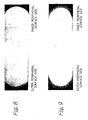
- Figs. 8 and 9 The nitriding results are shown in Figs. 8 and 9 .
- a side rail with nitriding on only the outer peripheral surface is shown in Fig. 8 .
- a side rail with nitriding on only the inner and outer peripheral surfaces is shown in Fig. 9 .
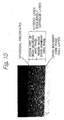
- the microstructure of the nitriding layer of both side rails are identical, an enlarged microstructure of the only one nitriding layer shown in Fig. 8 is shown in Fig. 10 .
- the compound surface layer is absent; only spheroidal precipitates are observed in the surface region of the nitrogen diffusion layer, which thickness of the region is of 1/3 or more of thickness of the nitriding layer, and the hard grain boundary phases ( ⁇ phase) are absent.
- the nitriding layer is present only on the outer peripheral surface of the coil set by the method shown in Fig. 6 .
- the nitriding layer is present on the inner and outer peripheral surfaces of the coil set by the method of Fig. 7 .
- the compound surface layer is absent in the nitriding layer of both examples.
- the hard grain boundary phases are absent in the surface region of the nitrogen diffusion layer, which the thickness of the region is of 1/3 or more of the thickness of the nitriding layer.
- Coil (side rails) set by the method shown in Fig. 7 are nitrided by gas nitriding.
- the conditions of gas nitriding are as follows:
- the microstructure of the resultant nitriding layer is shown in Fig. 11 .
- the compound surface layer and the hard grain boundary phases are observed in the sliding surface side of the nitriding layer. This is outside the scope of the present invention.
- Coil (side rails) set by the method shown in Fig. 7 are nitrided by ion nitriding.
- the conditions of ion nitriding are as follows:
- the microstructure of the resultant nitriding layer is shown in Fig. 12 .
- the compound surface layer and the hard grain boundary phases are observed in the sliding surface side of the nitriding layer. This is outside the scope of the present invention, too.
- the coil (side rails) set by the method shown in Fig. 7 are subjected to the radical nitriding under various conditions (Table 3).
- Table 3 The results (depth of nitriding layer, presence or absence of compound surface layer, presence or absence of hard grain boundary phases in the sliding surface side of the nitriding layer, and hardness at a depth of 20 ⁇ m from the surface of nitriding layer) are shown in Table 4.
- Comparative Example 5 low pressure
- Comparative Example 7 low flow-rate ratio of NH 3 gas
- Comparative Example 9 low voltage non-uniformity in nitriding thickness
- Comparative Example 6 high pressure
- Comparative Example 8 high flow-rate ratio of NH 3 gas
- Comparative Example 10 high voltage
- the aggressive property against the opposing material was evaluated.
- the front end of pin material was nitrided under the conditions of inventive Example and Comparative Example 1.
- the compound surface layer of the gas nitrided Comparative Example 1 was removed.
- the wear test was carried out.
- the hard grain boundary phases were absent on the sliding surface of the inventive Example.
- Comparative Example 1 the hard grain boundary phases were present on the sliding surface, from which the compound surface layer was removed.
- the wear test was carried out by a pin-on-drum type test under the following conditions.
- the pin wear of the Inventive Example is at the same level as that of the Comparative Example 1.
- the wear of drum material according to the present invention is 1/2 or less than that according to the Comparative Example 1. It is shown that the Inventive Example significantly decreases the wear amount of the opposing material. The aggressive property against the opposing material is, therefore, greatly mitigated.
- the nitriding layer of side rails according to the present invention has lessened aggressive property against the opposing material. Wear resistant properties of the liner and the ring groove are, therefore, outstandingly improved. Accordingly, it is possible to provide side rails used for a combined oil-control ring, which can maintain the oil-controlling performance for a long period of time.
Landscapes
- Chemical & Material Sciences (AREA)
- Engineering & Computer Science (AREA)
- Mechanical Engineering (AREA)
- General Engineering & Computer Science (AREA)
- Chemical Kinetics & Catalysis (AREA)
- Materials Engineering (AREA)
- Metallurgy (AREA)
- Organic Chemistry (AREA)
- Solid-Phase Diffusion Into Metallic Material Surfaces (AREA)
- Pistons, Piston Rings, And Cylinders (AREA)
Description
- The present invention relates to the steel side-rails of a combined oil-control ring used for an internal combustion engine and a nitriding method of same. More particularly, the present invention relates to a microstructure of the nitriding layer, and a method for forming the microstructure.
- A combined oil-control ring comprises a pair of side rails and a spacer expander for pushing the side rails in radial direction toward their outer peripheral sides and pressing them against an inner wall surface of a cylinder. A function of the oil-control ring is, therefore, to form an appropriate oil film on the inner wall of the cylinder and hence to lubricate piston rings and the cylinder. Another function is to scrape off excessive oil on the inner wall surface of the cylinder.
- There are two sliding surfaces on the side rail having the construction mentioned above. One of the sliding surfaces is outer peripheral surface of the side rail, which is brought into sliding with the inner wall of the cylinder. The other sliding surface is inner peripheral surface of the side rail, which is brought into contact with ears of a spacer expander.
- Accordingly, Japanese Unexamined Utility-Model Publication (kokai) No.
53-147309 5-44575 5-332451 7-4308 - Meanwhile, regarding the nitriding layer, Japanese Unexamined Patent Publication (kokai) No.
7-118826 7-316778 - Although pressing load of a spacer expander against the side rails is small, the pressing stress becomes considerably great because the contact area between the side rails and the spacer expander is small. Since the wear resistance of the nitriding layer itself should, therefore, be high, martensitic stainless steels having improved wear resistance, particularly SUS 440B equivalent materials, have been used for the nitriding base material.
- When the ion nitriding is applied to the base material mentioned above, the compound surface layer is not formed, but a nitrogen diffusion layer and hard grain-boundary phases, referred to as the gull layer by the persons skilled in the art, are formed. Such microstructure incurs problems as wear of the inner surface of the cylinder, and roughening of the ring groove, and resulting in increased oil consumption.
- The present inventors studied the wear of the steel materials with nitriding and discovered the following. The hard grain boundary phases mentioned above formed in the nitriding layer exert actually no influence upon the wear resistance of the nitrided material itself but considerably increases an aggressive property against an opposing material. The reason is elucidated to be that: relatively soft phases on the surface preferentially wear out; and, on the other hand, the wear of the hard grain boundary phases is so delayed that only these phases are brought into contact with the opposing material. This is comparable to a situation that surface of the opposing material is rubbed by a file.
-
JP 07316778 A 64-1956 - Accordingly,
JP 07316778 A JP 07316778 A - The present invention solves problems of the prior art that oil consumption is increased by the wear of the inner surface of the cylinder and roughening of the ring groove. The essence of the present invention resides in the microstructure of the nitriding layer, which is free of the compound surface layer and is also free of the hard grain boundary phase (ε phase) of high aggressive property on at least the sliding surface.
- The present invention is related to side rails, which are combined with a spacer expander to construct an oil-control ring, and wherein nitriding layers are formed on outer peripheral surfaces or inner and outer peripheral surfaces of side rails made of steel, consists of nitrogen diffusion layers free of compound surface layer, and has surface hardness of Hv 1000 or more and hard grain boundaries phoses are absent in surface region of the nitrogen diffusion layer.)
- The side rails are characterized in that said nitriding layers are free of hard grain boundary phases (ε phases) in the surface region of the nitrogen diffusion layers, said nitriding layers are obtainable by a radical nitriding under the conditions of 550 ~ 600°C of temperature, 0,5~5 Torr of pressure, 3/7 ~ 9/1 of flow rate ratio of NH3/H2, and -400 ~ -500V of voltage including pretreatment sputtering during temperature elevating up to the nitriding temperature, and in that the thickness of said surface region of the nitrogen diffusing layer is 1/3 or more of the thickness of said nitriding layer.
- Furthermore, the present invention relates to a method for nitriding side rails comprising the steps of:
- shaping wire material for side rails into a coil form;
- aligning outer peripheral surfaces of the coil using an inner surface of a sleeve, squeezing the coil vertically using a pressing jig (21) to bring adjacent upper and lower side surfaces of the coil into close contact with one another in the sleeve, and taking the coil with the pressing jig (21) out of the sleeve, thereby setting the coil with the jig; and
- nitriding the coil set with the jig in a radical nitriding furnace in the conditions of 550 ~ 600°C of temperature, 0,5 ~ 5 Torr of pressure, 3/7 ~ 9/1 of flow rate ratio of NH3/H2, and -400 ~ -500V of voltage including pretreatment sputtering during temperature elevating up to the nitriding temperature.
- The nitriding layer of side rails according to the present invention is free of the compound surface layer. There is, therefore, no need for removal of the compound surface layer after the nitriding.
- In addition, the hard grain boundary phases may be formed in the inner region of the nitrogen diffusion layer according to the present invention because of the following reason. While Cr28C6, precipitates in the base material, are almost transformed into CrN by nitriding, C (carbon) is expelled and diffuses toward the grain boundary region; and, a compound of Fe, C and N, particularly, the ε phase (that is, "hard grain boundary phase") is formed in the grain boundary when the nitrogen concentration in the grain boundary exceeds a certain level. The reason why the expelled C diffuses toward the grain boundary is attributable to the extremely low solubility of C in the martensitic stainless steel.
- The microstructure of nitriding layer according to the present invention is (a) no hard grain boundary phase is formed in the surface region of the nitrogen diffusion layer, and the hard grain boundary phases are formed in the inner region of the nitriding layer; or (b) the hard grain boundary phases are absent in the entire nitriding layer. Whether the microstructure (a) or (b) is formed depends on nitriding conditions, particularly, the thickness of the nitriding layer. The reason for the non-formation of the hard grain boundary phase is the very small C quantity in the grain boundaries.
- There are variable factors for forming the nitriding layer mentioned above, such as setting method of the side rails (coil), temperature, pressure, flow-rate ratio of NH8/H2, voltage and nitriding time in the radical nitriding, which is one type of plasma nitriding. The nitriding layer having the features mentioned above can be formed by nitriding conditions such as the factors mentioned above.
- There is actually no difference during the initial sliding period between the wear of side rails having the microstructure free of the hard grain boundary phase (A) and that of side rails having the microstructure with the hard grain boundary phases (B). When sliding advances to a certain extent, wear within the crystal grains occurs in the side rails (B), with the result that the convex hard grain boundary phases remain on the surface of the side rails and shave the opposing material. When the sliding proceeds further, the opposing material may be worn out the convex hard grain boundary phases, and the initial sliding conditions may then be realized. However, such wear progress is a rare case. The opposing material is greatly worn out, because the hard grain boundary phases protrude from and are firmly held by the adjacent crystal grains. Contrary to this, in the side rails (A), hard grain boundary phases are absent in the microstructure of a surface region of the nitrogen diffusion layer, that is, the sliding surface. The aggressive property described above, therefore, does not generate. Spherical precipitates within the grains mitigate the wear of grains by the opposing material. The grain-boundaries are more liable to be worn out than the crystal grains. But preferential wear of the grain boundaries by the opposing material does not occur.
-
-
Figure 1 shows an embodiment of a combined oil-control ring, an element of which is the side rails. -
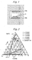
Figure 2 is an Fe-N-C ternary diagram at 580°C. -
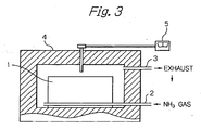
Figure 3 shows a schematic of gas nitriding apparatus. -
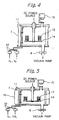
Figure 4 shows a schematic of ion nitriding apparatus. -
Figure 5 shows a schematic of radical nitriding apparatus. -
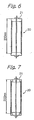
Figure 6 shows a coil (side rails) set with jig for nitriding only the outer peripheral surface of the side rails. -
Figure 7 shows a coil (side rails) set with jig for nitriding the inner and outer peripheral surfaces of the side rails. -
Figure 8 shows the cross-sectional microstructure of a side rail having the nitriding layer only on the outer peripheral surface. -
Figure 9 shows the cross-sectional microstructure of a side rail having the nitriding layers only on the inner and outer peripheral surfaces. -
Figure 10 is an enlarged view of the cross-sectional microstructure of nitriding layer according to the present invention. -
Figure 11 is an enlarged view of the cross-sectional microstructure of the nitriding layer by gas nitriding according to Comparative Example 1 -
Figure 12 is an enlarged view of the cross-sectional microstructure of the nitriding layer by ion nitriding according to Comparative Example 2 - Referring to
Fig. 1 , a combined oil-control ring is shown. This ring is made of steel and is mounted in an oil-ring groove of a piston inserted in a cylinder. The combined oil-control ring consists of a pair of the annular, upper andlower side rails 30a, b having a gap, and anannular spacer expander 31 having a gap. - The spacer expander has a meander form in the axial direction. It has outer plateau portions for holding and separating the side rails and inner ear portions for exerting pressure on the
side rails 30a,b. - The fundamental theory to avoid the formation of the ε phase in the grain boundary is explained hereinafter. The nitriding layer is formed by reaction of active species on the surface of the base material and subsequent diffusion of the nitrogen. The reaction speed is not generally equal to the diffusion speed. Thickness of the nitriding layer is determined by diffusion. Meanwhile, the microstructure and the phase morphology of the nitriding layer itself are greatly dependent upon the reaction speed of the active species.
- For example, when the nitriding layer formed on the surface comprises a compound surface layer, the reaction speed of an active species is greater than its diffusion speed, and the nitrogen concentration in the vicinity of the surface gradually increases. When this nitrogen concentration exceeds approximately 5.8 % by weight at 580°C, the phase transformation of r'+ ε occurs as shown in
Fig. 2 . These phases, which have certain thickness, are referred to as the compound surface layer. - On the other hand, when the reaction speed is less than or equal to the diffusion speed, nitrogen does not concentrate in the vicinity of the surface. The phase transformation to γ' phase and ε phase, therefore, does not occur but only the diffusion layer is formed. Any nitriding not to form the compound surface layer is carried out under the concept described above.
- As described hereinabove, the grain boundary ε phases may or may not be formed depending upon the difference between the nitrogen quantity reacted and diffused in the grain boundaries and the nitrogen quantity diffused from the grain boundaries. Particularly, since C, which is expelled from the carbide due to nitriding, is present in the grain boundaries, the nitrogen concentration required for forming the ε phase greatly shifts to a lower level. As is depicted in
Fig. 2 , the phase diagram shows that when approximately 0.5 % by weight of C is dissolved in Fe, then, the nitrogen concentration required for forming the ε phase is decreased to approximately to 2% by weight. - The nitriding conditions required for not forming the ε phase in the grain boundaries are, therefore, as follows.
- (1) High nitriding temperature to accelerate diffusion in the grain boundary portions.
- (2) Low nitrogen potential to decrease the nitrogen quantity reacted with the surface of the base material.
- (3) Low voltage to decrease the nitrogen quantity reacted with the surface of the base material under an electric field, such as plasma nitriding.
- (4) Sputtering is carried out to discharge from the surface C, which is expelled by nitriding and is present in the grain boundaries in order to increase the nitrogen concentration required for forming the ε phase.
- A nitriding apparatus and the nitriding conditions, which satisfy the conditions mentioned above, should be controlled not to form the hard grain boundary phases.
- What kind of nitriding method can satisfy conditions (1) ~ (4) ? The radical nitriding apparatus is the most appropriate. Evidently, the nitriding layer free of the hard grain boundary phase (ε phase) can be formed by means of the gas nitriding and the ion nitriding, provided that the nitriding conditions are appropriate. The gas nitriding, the ion nitriding and the radical nitriding methods are illustrated in
Figs. 3 ,4 and 5 , respectively. In addition, the respective nitriding methods are shown in Table 1 for comparison.Table 1: Comparison of Nitriding Methods Gas Nitriding Ion Nitriding Radical Nitriding Supplying Gases NH3/N2 N2/H2 NH3/H2 Heat Source External Heater Heating by Sputtering External Heater (90%) + Sputtering (10%) Voltage (V) 0 560 - 700 400 - 500 Pressure (Torr) 760 1 - 5 0.5 - 5 Temperature (°C) 500 - 590 500 - 590 500 - 590 Heat Generation No Large Small Nitriding Reactive Species NH Radicals N Ions NH Radicals Reaction CVD PVD Mainly CVD - First, in the gas nitriding shown in
Fig. 3 , materials to be treated are arranged in a work-piece chamber 1 located in a nitriding furnace. NH3 gas and carrier gas are ejected through thegas conduit 2 into the work-piece chamber 1 and then ejected through an appropriate outlet (not shown) into the furnace. The gases are discharged through theconduit 3 out of the furnace and are made to safety by a waste gas apparatus. The materials to be treated are heated by an external heater 44. In order to control temperature in the furnace interior, atemperature controller 5 is used. In such gas nitriding method, it is possible to elevate the temperature according to condition (1) mentioned above, and to decrease the NH3 concentration according to condition (2), which stipulates adjustment of the nitriding potential. However, since the gas nitriding method has no function to discharge C from the surface according to condition (4) mentioned above, formation of hard grain boundary phases cannot be suppressed unless the NH3 concentration is decreased to considerably low levels. However, when the NH3 concentration is decreased to such low level, the nitriding time has to be prolonged and often results in non-uniformity in nitriding depth. It is, therefore, impractical to obtain by the gas nitriding method a nitriding layer free of the hard grain boundary phase. - Second, in the ion nitriding method shown in
Fig. 4 , the interior of achamber 7 is evacuated by a vacuum pump (not shown). Anautomatic pressure controller 8 controls pressure in thechamber 7. Reacting gases evacuated are made to safety by the waste gas apparatus. The raw material gases, H2 and N2, are ejected via the respective mass-flow controllers 10 and anozzle 11 into thechamber 7. Meanwhile, since the work pieces 12 (materials to be treated) are placed on theelectrode 14 which is in electrical contact with the direct current source (not shown), a sheath region, which is a voltage drop region, is formed on the surface of the work pieces, and gases are ionized in the sheath region. Ionized gases are then reacted with the surface of the work pieces. A pyroscope for observing the furnace interior is denoted by thereference numeral 15. - Since no external heater is provided in such nitriding method, the nitriding temperature of work pieces is attained only by means of raising the voltage. In other words, the nitriding temperature is attained only by the sputtering effect. Since the voltage is high, the conditions (4) and (1) are attained. That is, the sputtering discharges out from the surface C present in the grain boundaries. The temperature is so high that the diffusion speed increases. However, since the voltage is high, the reacting nitrogen quantity is increased contrary to condition (3). It is, therefore, extremely difficult to suppress the formation of the ε phase in the grain boundaries.
- The radical nitriding method shown in
Fig. 5 has actually the same construction as the ion nitriding apparatus and is additionally provided with anexternal heater 16 in contrast to the ion nitriding methods described above. The radical nitriding method is provided with anexternal heater 16 and uses the NH3 gas, which is highly active, as the raw material gas, and can therefore advantageously determine the temperature and voltage independently of one another. Specifically, the temperature is elevated and maintained mainly by theexternal heater 16. Thus the diffusion speed of nitrogen in the work pieces can be increased. On the other hand, the voltage can be as low as possible. The main purpose for this is to discharge C, which is present in the grain boundaries in the vicinity of the surface of the work pieces. The voltage can be as low as possible to activate NH3 and hence to suppress the reaction speed of the nitrogen sources. The nitriding conditions, described above can satisfy all of the four conditions for suppressing the formation of the hard grain boundary phases. That is, there is no major difficulty in the radical nitriding method for not forming the hard grain boundary phases. - The radical nitriding was carried out in the examples of the present invention for the reasons described hereinabove.
- The base material of side rails according to the present invention may be basically any grade of steel for nitriding. The nitriding layer free of the hard grain boundary phase as intended in the present invention can be formed on such steels for nitriding. All of the steels for nitriding are, therefore, included in the present invention. Desirably, the one having good sliding property is, however, used for the side rails. Among the steels for nitriding, martensitic stainless steel, particularly SUS 440B series steel for nitriding, in which CrN precipitates are formed after nitriding, is the most desirable.
- Details of the method for nitriding side rails are hereinafter described.
- According to a setting method of side rails, the
rails 20 shaped into a coil form are squeezed vertically by means of apressing jig 21 in such a manner that adjacent upper and lower surfaces of the rails are brought into close contact with one another as shown inFig. 6 . When the only outer peripheral surface is to be nitrided, the pressing jig should have a cap form so as not to nitride the inner peripheral surface of rails. When thepressing jig 21 is in the form of a cap, a closed space is formed by the pressing jig and the inner peripheral surface of rails. An electric field is not formed on the inner peripheral surface of the rails and the pressing jig according to the Gauss law. Glow discharge, therefore, does not occur on these surfaces, which are therefore not nitrided. - On the other hand, when the inner and outer peripheral surfaces are to be nitrided, an open space is formed close to the inner peripheral surface of the rails. The apertures 22 must therefore be opened through the
pressing jig 21 so as to connect the open space with the exterior space as shown inFig. 7 . Since the size of the apertures 22 determines the electric field, the thickness of the nitriding layer on the inner peripheral surface of side rails can be adjusted by controlling the size of the apertures 22. - Next, with regard to preferable nitriding conditions, sputtering is carried out during temperature elevating stage up to the nitriding temperature. A purpose of the sputtering is to utilize it for eliminating the oxide film and the passive film present on the surface and heating the side rails. The atmosphere gas at the sputtering is preferably H2 or Ar.
- Further, the nitriding temperature set by the external heater is preferably 550°C or more and 600°C or less. Below 550°C, the diffusion speed of nitrogen is too slow to avoid formation of hard grain boundary phases. Above 600°C, the base material is annealed and softened, with the result the nitriding layer also softens. The wear resistance is thus lowered. Appropriate temperature is in a range of from 570°C to 590°C.
- Gas pressure set by the
automatic pressure controller 8 is preferably from 0.5 to 5 Torr. Below 0.5 Torr, the NH3 potential is too low for the nitriding to proceed. Above 5 Torr, the reacting nitrogen quantity is too large to avoid the formation of hard grain boundary phases. Optimum gas pressure is in a range of from 1 to 3 Torr. - The NH3/H2 ratio, which is set by a mass-
flow controller 10, is preferably in a range of from 3/7 to 9/1 in terms of the flow-rate ratio. Below 3/7 of the NH3/H2 ratio, the nitriding speed is too slow and is impractical. Above 9/1 of the NH3/H2 ratio, the NH3/H2 potential is too high to avoid formation of hard grain boundary phases. Optimum NH3/H2 ratio is from 7/3 to vicinity of 8/2. - The voltage is in a range of from -400V to -550V. Above -400V (below 400V in the absolute value), the NH radicals formed are too few to contribute to the nitriding. In addition, since sputtering is not effective to discharge C, it is difficult to avoid the formation of hard grain boundary phases. Below -550V (above 550V in the absolute value), the voltage and hence the reaction speed of radicals are so high that it is difficult to avoid the formation of hard grain boundary phases. Optimum voltage is in a range of from -475V to -525V. The voltage is selected within this range to attain optimum reacting nitrogen quantity and discharging C quantity by sputtering.
- The present invention is hereinafter explained in detail with reference to the examples.
- The chemical composition of the base material used in the present invention is shown in Table 2.
Table 2 Chemical Composition (Weight %) of Base Material of Side Rails Used in Present Invention Element C Si Mn P S Cr Mo V Analysis Value 0.86 0.38 0.32 0.030 0.001 17.28 1.09 0.10 - A wire used for the side rails had a cross-sectional size of 0.4 × 2.02 mm and the chemical composition shown in Table 2. This wire was shaped into a coil form. The shaped coil had 76mm of outer diameter and 340mm of length. This coil was located in a sleeve in such a manner that no clearance is formed between the outer periferal surfaces of the coil and the inner surface of the sleeve. The coil is then squeezed vertically by means of the
pressing jig 21 as shown inFigs. 6 and 7 . The coil set with jig shown inFig. 6 is used for producing the side rails with nitriding only on the outer peripheral surfaces. The coil set with jig shown inFig. 7 is used for producing the side rails with nitriding only the inner and outer peripheral surfaces. - The coil set with jig described above is located in a radical nitriding furnace. Pretreatment sputtering was carried out during the temperature elevating. The radical nitriding was subsequently carried out. The conditions are as follows:
- (1) Pretreatment Conditions (during the temperature elevating)
- Pressure: 0.8 Torr
- Gas: H2
- Voltage: - 500V
- Temperature: 540°C or more and up to 580°C
- Temperature Elevating Speed: 1°C/minute
- (2) Nitriding Conditions
- Temperature: 580°C
- Pressure: 2 Torr
- Gas: NH3, H2
- Flow Rate of NH3/H2: 7/3
- Voltage: - 500V
- Nitriding Time: 3 hours
- The nitriding results are shown in
Figs. 8 and 9 . A side rail with nitriding on only the outer peripheral surface is shown inFig. 8 . A side rail with nitriding on only the inner and outer peripheral surfaces is shown inFig. 9 . Since the microstructure of the nitriding layer of both side rails are identical, an enlarged microstructure of the only one nitriding layer shown inFig. 8 is shown inFig. 10 . As is apparent fromFig. 10 , the compound surface layer is absent; only spheroidal precipitates are observed in the surface region of the nitrogen diffusion layer, which thickness of the region is of 1/3 or more of thickness of the nitriding layer, and the hard grain boundary phases (ε phase) are absent. - As shown in
Fig. 8 , the nitriding layer is present only on the outer peripheral surface of the coil set by the method shown inFig. 6 . The nitriding layer is present on the inner and outer peripheral surfaces of the coil set by the method ofFig. 7 . The compound surface layer is absent in the nitriding layer of both examples. In addition, the hard grain boundary phases are absent in the surface region of the nitrogen diffusion layer, which the thickness of the region is of 1/3 or more of the thickness of the nitriding layer. - Coil (side rails) set by the method shown in
Fig. 7 are nitrided by gas nitriding. The conditions of gas nitriding are as follows: - Temperature: 575°C
- Gas: NH3 (90%) - dry air (10%)
- Pressure: 1 atm
- Nitriding Time: 6 hours
- The microstructure of the resultant nitriding layer is shown in
Fig. 11 . The compound surface layer and the hard grain boundary phases are observed in the sliding surface side of the nitriding layer. This is outside the scope of the present invention. - Coil (side rails) set by the method shown in
Fig. 7 are nitrided by ion nitriding. The conditions of ion nitriding are as follows: - Temperature: 550°C
- Gas: N2/H2 = 7/3 (flow-rate ratio)
- Voltage: 600V
- Pressure: 4 Torr
- Nitriding Time: 20 hours
- The microstructure of the resultant nitriding layer is shown in
Fig. 12 . The compound surface layer and the hard grain boundary phases are observed in the sliding surface side of the nitriding layer. This is outside the scope of the present invention, too. - The coil (side rails) set by the method shown in
Fig. 7 are subjected to the radical nitriding under various conditions (Table 3). The results (depth of nitriding layer, presence or absence of compound surface layer, presence or absence of hard grain boundary phases in the sliding surface side of the nitriding layer, and hardness at a depth of 20 µm from the surface of nitriding layer) are shown in Table 4. - In Comparative Example 3, since the nitriding temperature was low, non-uniformity in nitriding thickness, the compound surface layer and the hard grain boundary phases were observed.
- In Comparative Example 4, since the nitriding temperature was high, the hardness of the nitriding layer was as low as HV850.
- In Comparative Example 5 (low pressure), Comparative Example 7(low flow-rate ratio of NH3 gas), and Comparative Example 9 (low voltage) non-uniformity in nitriding thickness resulted. In Comparative Example 6 (high pressure), Comparative Example 8 (high flow-rate ratio of NH3 gas), and Comparative Example 10 (high voltage), the compound surface layer and hard grain boundary phases were observed.
- As is described hereinabove, all production methods, which lie outside the scope of the present invention, could not provide a solution to the problems of the prior arts.
Table 3 Nitriding Conditions of Present Invention And Comparative Examples 3 - 10 Temperature (°C) Pressure (Torr) NH3/H2 (Flow Rate Ratio) Voltage Nitriding Time (minutes) Invention 580 2 7/3 500 180 Comparative Example-3 545 2 7/3 500 180 Comparative Example-4 605 2 7/3 500 180 Comparative Example-5 580 0.4 7/3 500 180 Comparative Example-6 580 5.1 7/3 500 180 Comparative Example-7 580 2 2.9/7.1 500 180 Comparative Example-8 580 2 9.1/0.9 500 180 Comparative Example-9 580 2 7/3 390 180 Comparative Example-10 580 2 7/3 560 180 Table 4 Nitriding Results of Present Invention and Comparative Examples 3 through 10 Thickness of Nitride Layer (µm) Compound Surface Layer Hard Grain Boundary Phases Hardness (Hv) Invention 57 Absent Absent 1100 Comparative Example-3 Non-Uniformity Present Present 1205 Comparative Example-4 69 Absent Absent 850 Comparative Example-5 Non-Uniformity Absent Absent Measurement Impossible Comparative Example-6 65 Present Present 1153 Comparative Example-7 Non-Uniformity Absent Absent Measurement Impossible Comparative Example-8 64 Present Present 1025 Comparative Example-9 Non-Uniformity Absent Absent Measurement Impossible Comparative Example-10 62 Present Present 1020 - Subsequently, the aggressive property against the opposing material was evaluated. For this purpose, the front end of pin material was nitrided under the conditions of inventive Example and Comparative Example 1. The compound surface layer of the gas nitrided Comparative Example 1 was removed. Then, the wear test was carried out. The hard grain boundary phases were absent on the sliding surface of the inventive Example. In Comparative Example 1, the hard grain boundary phases were present on the sliding surface, from which the compound surface layer was removed.
- The wear test was carried out by a pin-on-drum type test under the following conditions.
- Drum Material (Opposing Material): FC250
- Frictional Sliding Speed: 0.25m/second
- Testing Load: 39.2N
- Testing Time: 6 hours
- Lubricating Conditions: dropping of sulfuric-acid aqueous solution (PH = 2), at 0.1ce/second
- The test results are as shown in Table 5.
Table 5 Wear Amount of Pin (µm) Wear Amount of Drum (µm) Inventive Example 2.6 1.2 Comparative Example 1 2.7 2.6 - As shown in
Fig. 5 , the pin wear of the Inventive Example is at the same level as that of the Comparative Example 1. The wear of drum material according to the present invention is 1/2 or less than that according to the Comparative Example 1. It is shown that the Inventive Example significantly decreases the wear amount of the opposing material. The aggressive property against the opposing material is, therefore, greatly mitigated. - The nitriding layer of side rails according to the present invention has lessened aggressive property against the opposing material. Wear resistant properties of the liner and the ring groove are, therefore, outstandingly improved. Accordingly, it is possible to provide side rails used for a combined oil-control ring, which can maintain the oil-controlling performance for a long period of time.
Claims (2)
- Side rails (30a, 30b) used for a combined oil-control ring, which are combined with a spacer expander (31), wherein nitriding layers are formed on outer peripheral surfaces or inner and outer peripheral surfaces of the side rails (30a, 30b) made of steel, consisting of nitrogen diffusion layers free of compound surface layer, and having surface hardness of Hv 1000 or more,
characterized in that
said nitriding layers are free of hard grain boundary phases (∈ phases) in the surface region of the nitrogen diffusion layers, said nitriding layers are obtainable by a radical nitriding under the conditions of 550 ~ 600°C of temperature, 0,5 ~ 5 Torr of pressure, 3/7 ~ 9/1 of flow rate ratio of NH3/H2, and -400 - -500V of voltage including pretreatment sputtering during temperature elevating up to the nitriding temperature,
and in that the thickness of said surface region of the nitrogen diffusing layer is 1/3 or more of the thickness of said nitriding layer. - A method for nitriding side rails (20) comprising the steps of:shaping wire material for side rails into a coil form;aligning outer peripheral surfaces of the coil using an inner surface of a sleeve, squeezing the coil vertically using a pressing jig (21) to bring adjacent upper and lower side surfaces of the coil into close contact with one another in the sleeve, and taking the coil with the pressing jig (21) out of the sleeve, thereby setting the coil with the jig; andnitriding the coil set with the jig in a radical nitriding furnace in the conditions of 550 ~ 600°C of temperature, 0,5 ~ 5 Torr of pressure, 3/7 ~ 9/1 of flow rate ratio of NH3/H2, and -400 ~ 500V of voltage including pretreatment sputtering during temperature elevating up to the nitriding temperature.
Applications Claiming Priority (3)
| Application Number | Priority Date | Filing Date | Title |
|---|---|---|---|
| JP2002246567 | 2002-08-27 | ||
| JP2002246567 | 2002-08-27 | ||
| PCT/JP2003/010800 WO2004020878A1 (en) | 2002-08-27 | 2003-08-26 | Side rail for combination oil ring and method of nitriding the same |
Publications (3)
| Publication Number | Publication Date |
|---|---|
| EP1533548A1 EP1533548A1 (en) | 2005-05-25 |
| EP1533548A4 EP1533548A4 (en) | 2008-09-03 |
| EP1533548B1 true EP1533548B1 (en) | 2012-10-17 |
Family
ID=31972423
Family Applications (1)
| Application Number | Title | Priority Date | Filing Date |
|---|---|---|---|
| EP03791310A Expired - Lifetime EP1533548B1 (en) | 2002-08-27 | 2003-08-26 | Side rail for combination oil ring and method of nitriding the same |
Country Status (8)
| Country | Link |
|---|---|
| US (1) | US20040262847A1 (en) |
| EP (1) | EP1533548B1 (en) |
| JP (1) | JP4603359B2 (en) |
| KR (1) | KR100636582B1 (en) |
| CN (1) | CN1321281C (en) |
| BR (1) | BRPI0306156B1 (en) |
| TW (1) | TWI258547B (en) |
| WO (1) | WO2004020878A1 (en) |
Families Citing this family (16)
| Publication number | Priority date | Publication date | Assignee | Title |
|---|---|---|---|---|
| WO2005012156A2 (en) | 2003-07-31 | 2005-02-10 | Happijac Company | System and method for moving objects |
| JP2006213997A (en) * | 2005-02-07 | 2006-08-17 | Honda Motor Co Ltd | Method for nitriding iron group alloy base material |
| WO2007110905A1 (en) * | 2006-03-24 | 2007-10-04 | Honda Motor Co., Ltd. | Method of nitriding of iron group base alloy substrate |
| JP5260014B2 (en) * | 2007-09-28 | 2013-08-14 | 電化皮膜工業株式会社 | Cr-N film forming method |
| US9598761B2 (en) * | 2009-05-26 | 2017-03-21 | The Gillette Company | Strengthened razor blade |
| BRPI0905228B1 (en) | 2009-12-29 | 2017-01-24 | Mahle Metal Leve Sa | crack propagation resistant nitrided piston ring |
| JP5557562B2 (en) * | 2010-03-10 | 2014-07-23 | Tpr株式会社 | Combination oil ring |
| JP5587285B2 (en) * | 2011-12-21 | 2014-09-10 | Tpr株式会社 | Combination oil ring |
| CA2813159A1 (en) * | 2012-05-24 | 2013-11-24 | Sulzer Metco Ag | Method of modifying a boundary region of a substrate |
| JP2014209018A (en) * | 2012-08-30 | 2014-11-06 | 日本ピストンリング株式会社 | Combination oil ring |
| JP5980966B2 (en) * | 2015-01-09 | 2016-08-31 | 株式会社リケン | Combination oil control ring |
| JP6530200B2 (en) * | 2015-02-23 | 2019-06-12 | 株式会社リケン | side rail |
| WO2016159269A1 (en) * | 2015-03-31 | 2016-10-06 | 日本ピストンリング株式会社 | Combined oil ring |
| BR112019003747B1 (en) * | 2017-09-29 | 2022-08-30 | Tpr Co., Ltd | SEGMENT, COMBINATION OIL RING, AND MANUFACTURING METHOD FOR A SEGMENT |
| JP6389970B1 (en) * | 2018-01-16 | 2018-09-12 | Tpr株式会社 | Combination oil ring |
| CN115306580B (en) * | 2022-08-29 | 2024-03-01 | 奇瑞汽车股份有限公司 | Method for improving quality of engine oil ring scraping blade |
Citations (6)
| Publication number | Priority date | Publication date | Assignee | Title |
|---|---|---|---|---|
| JPS585456A (en) * | 1981-02-24 | 1983-01-12 | Nippon Piston Ring Co Ltd | Combination piston ring |
| US5176760A (en) * | 1991-11-22 | 1993-01-05 | Albert Young | Steel article and method |
| US5308089A (en) * | 1991-08-09 | 1994-05-03 | Teikoku Piston Ring Co., Ltd. | Combined oil ring |
| JPH06325946A (en) * | 1993-05-13 | 1994-11-25 | Hitachi Ferrite Ltd | Coaxial rotary transformer |
| JPH07316778A (en) * | 1994-03-30 | 1995-12-05 | Nippon Piston Ring Co Ltd | Nitrided piston ring |
| GB2315079A (en) * | 1996-07-08 | 1998-01-21 | Rhp Bearings Ltd | Ion nitriding surface treatment of rolling element bearing steels |
Family Cites Families (21)
| Publication number | Priority date | Publication date | Assignee | Title |
|---|---|---|---|---|
| JPS5846924B2 (en) | 1977-05-25 | 1983-10-19 | 日本車輌製造株式会社 | Control device for electric car formation |
| JPS558492A (en) * | 1978-07-05 | 1980-01-22 | Kawasaki Heavy Ind Ltd | Ion nitriding treatment method of stainless steel or the like |
| JPS60153456A (en) * | 1984-01-23 | 1985-08-12 | Nippon Piston Ring Co Ltd | Steel piston ring |
| JPS60206962A (en) * | 1984-03-30 | 1985-10-18 | Riken Corp | Steel piston ring for internal-combustion engine |
| JPH0625597B2 (en) * | 1985-11-20 | 1994-04-06 | 株式会社リケン | piston ring |
| JPS62223545A (en) | 1986-03-24 | 1987-10-01 | Taikisha Ltd | Air conditioning system |
| JPH07118826B2 (en) | 1987-09-23 | 1995-12-18 | 山武ハネウエル株式会社 | Building management system |
| JPH02236257A (en) * | 1989-03-08 | 1990-09-19 | Nippon Steel Corp | Martensitic stainless steel having high strength and excellent in corrosion resistance and stress corrosion cracking resistance and its production |
| JPH089766B2 (en) * | 1989-07-10 | 1996-01-31 | 大同ほくさん株式会社 | Steel nitriding method |
| EP0486320B1 (en) * | 1990-11-15 | 1996-07-03 | Teikoku Piston Ring Co. Ltd. | Method of manufacturing a side rail of combined oil ring |
| US5089067A (en) * | 1991-01-24 | 1992-02-18 | Armco Inc. | Martensitic stainless steel |
| US5154433A (en) * | 1991-06-14 | 1992-10-13 | Teikoku Piston Ring Co., Ltd. | Piston ring |
| JPH05332451A (en) | 1992-05-29 | 1993-12-14 | Nippon Piston Ring Co Ltd | Side rail for combination oil ring and manufacture thereof |
| US5534081A (en) * | 1993-05-11 | 1996-07-09 | Honda Giken Kogyo Kabushiki Kaisha | Fuel injector component |
| US5415706A (en) * | 1993-05-28 | 1995-05-16 | Abb Management Ag | Heat- and creep-resistant steel having a martensitic microstructure produced by a heat-treatment process |
| US5971484A (en) * | 1997-12-03 | 1999-10-26 | Steelcase Development Inc. | Adjustable armrest for chairs |
| CA2318408A1 (en) * | 1998-01-16 | 1999-07-22 | Theodore Kosa | Free-machining martensitic stainless steel |
| JP4724275B2 (en) * | 2000-07-17 | 2011-07-13 | 株式会社リケン | Piston ring excellent in scuffing resistance, cracking resistance and fatigue resistance, and manufacturing method thereof |
| JP2002194527A (en) * | 2000-12-27 | 2002-07-10 | Kawasaki Heavy Ind Ltd | Nitriding equipment using electron beam excited plasma |
| JP2003287130A (en) * | 2002-03-29 | 2003-10-10 | Riken Corp | Manufacturing method of side rail of combination oil ring |
| JP2003313649A (en) * | 2002-04-24 | 2003-11-06 | Toyota Motor Corp | Nitriding method and sintered member |
-
2003
- 2003-08-20 TW TW092122849A patent/TWI258547B/en not_active IP Right Cessation
- 2003-08-26 US US10/491,048 patent/US20040262847A1/en not_active Abandoned
- 2003-08-26 WO PCT/JP2003/010800 patent/WO2004020878A1/en not_active Ceased
- 2003-08-26 KR KR1020047005820A patent/KR100636582B1/en not_active Expired - Fee Related
- 2003-08-26 EP EP03791310A patent/EP1533548B1/en not_active Expired - Lifetime
- 2003-08-26 CN CNB038012685A patent/CN1321281C/en not_active Expired - Fee Related
- 2003-08-26 JP JP2004532716A patent/JP4603359B2/en not_active Expired - Fee Related
- 2003-08-26 BR BRPI0306156-6A patent/BRPI0306156B1/en not_active IP Right Cessation
Patent Citations (6)
| Publication number | Priority date | Publication date | Assignee | Title |
|---|---|---|---|---|
| JPS585456A (en) * | 1981-02-24 | 1983-01-12 | Nippon Piston Ring Co Ltd | Combination piston ring |
| US5308089A (en) * | 1991-08-09 | 1994-05-03 | Teikoku Piston Ring Co., Ltd. | Combined oil ring |
| US5176760A (en) * | 1991-11-22 | 1993-01-05 | Albert Young | Steel article and method |
| JPH06325946A (en) * | 1993-05-13 | 1994-11-25 | Hitachi Ferrite Ltd | Coaxial rotary transformer |
| JPH07316778A (en) * | 1994-03-30 | 1995-12-05 | Nippon Piston Ring Co Ltd | Nitrided piston ring |
| GB2315079A (en) * | 1996-07-08 | 1998-01-21 | Rhp Bearings Ltd | Ion nitriding surface treatment of rolling element bearing steels |
Also Published As
| Publication number | Publication date |
|---|---|
| CN1321281C (en) | 2007-06-13 |
| BR0306156A (en) | 2004-10-19 |
| TWI258547B (en) | 2006-07-21 |
| EP1533548A4 (en) | 2008-09-03 |
| EP1533548A1 (en) | 2005-05-25 |
| US20040262847A1 (en) | 2004-12-30 |
| JP4603359B2 (en) | 2010-12-22 |
| BRPI0306156B1 (en) | 2015-06-02 |
| JPWO2004020878A1 (en) | 2005-12-15 |
| KR100636582B1 (en) | 2006-10-19 |
| KR20050039692A (en) | 2005-04-29 |
| WO2004020878A1 (en) | 2004-03-11 |
| CN1568408A (en) | 2005-01-19 |
| TW200404133A (en) | 2004-03-16 |
Similar Documents
| Publication | Publication Date | Title |
|---|---|---|
| EP1533548B1 (en) | Side rail for combination oil ring and method of nitriding the same | |
| WO2000006960A1 (en) | Process for nitriding of metal containing materials | |
| EP0707092B1 (en) | Slide member and method of its production | |
| CN102947477A (en) | Process for carbonitriding metallic components | |
| CN112795863A (en) | Titanium alloy surface ion carbonitriding processing apparatus | |
| EP2098610A1 (en) | Hard coating film excellent in lubrication characteristics, process for formation thereof, and tool for the plastic working of metal | |
| MX2013015262A (en) | Manufacturing method for a drive belt ring component. | |
| WO1998003693A1 (en) | Titanium-base decoration member and method for curing the same | |
| EP3006601A1 (en) | Method for manufacturing mold for cold working use | |
| RU2409699C1 (en) | Procedure for forming non-uniform structure of material at nitriding in glow discharge | |
| CN114032470A (en) | A kind of carburized bearing steel and preparation method thereof | |
| CN113846284B (en) | A kind of ion nitriding process for 25Cr2Ni3Mo material | |
| CN110656301B (en) | Preparation method of controllable nitriding-PVD (physical vapor deposition) composite coating for high-speed steel tool | |
| Sanchette et al. | Single cycle plasma nitriding and hard coating deposition in a cathodic arc evaporation device | |
| CN103194719A (en) | High-performance ceramic piston ring manufacturing technology | |
| RU2413793C2 (en) | Procedure for ion-plasma treatment of surface of metal cutting tool made out of high speed powder steel | |
| RU2241782C1 (en) | Method for ionic-plasma treatment of cutting tool steel surface | |
| JP3464651B2 (en) | Air motor components | |
| RU2291227C1 (en) | Construction-steel parts surface hardening method | |
| JP2002115045A (en) | Film deposition method, and vane for movable vane compressor | |
| JPH07316778A (en) | Nitrided piston ring | |
| JP2003313649A (en) | Nitriding method and sintered member | |
| JP2000054108A (en) | Die for forging | |
| JPS5993870A (en) | Manufacture of vane for rotary compressor | |
| CN115595532B (en) | A multi-layer hard coating and its preparation method and application |
Legal Events
| Date | Code | Title | Description |
|---|---|---|---|
| PUAI | Public reference made under article 153(3) epc to a published international application that has entered the european phase |
Free format text: ORIGINAL CODE: 0009012 |
|
| 17P | Request for examination filed |
Effective date: 20040614 |
|
| AK | Designated contracting states |
Kind code of ref document: A1 Designated state(s): AT BE BG CH CY CZ DE DK EE ES FI FR GB GR HU IE IT LI LU MC NL PT RO SE SI SK TR |
|
| A4 | Supplementary search report drawn up and despatched |
Effective date: 20080805 |
|
| 17Q | First examination report despatched |
Effective date: 20081216 |
|
| GRAP | Despatch of communication of intention to grant a patent |
Free format text: ORIGINAL CODE: EPIDOSNIGR1 |
|
| GRAS | Grant fee paid |
Free format text: ORIGINAL CODE: EPIDOSNIGR3 |
|
| GRAA | (expected) grant |
Free format text: ORIGINAL CODE: 0009210 |
|
| AK | Designated contracting states |
Kind code of ref document: B1 Designated state(s): AT BE BG CH CY CZ DE DK EE ES FI FR GB GR HU IE IT LI LU MC NL PT RO SE SI SK TR |
|
| REG | Reference to a national code |
Ref country code: GB Ref legal event code: FG4D |
|
| REG | Reference to a national code |
Ref country code: CH Ref legal event code: EP |
|
| REG | Reference to a national code |
Ref country code: IE Ref legal event code: FG4D |
|
| REG | Reference to a national code |
Ref country code: AT Ref legal event code: REF Ref document number: 580069 Country of ref document: AT Kind code of ref document: T Effective date: 20121115 |
|
| REG | Reference to a national code |
Ref country code: DE Ref legal event code: R096 Ref document number: 60342386 Country of ref document: DE Effective date: 20121213 |
|
| REG | Reference to a national code |
Ref country code: AT Ref legal event code: MK05 Ref document number: 580069 Country of ref document: AT Kind code of ref document: T Effective date: 20121017 |
|
| REG | Reference to a national code |
Ref country code: NL Ref legal event code: VDEP Effective date: 20121017 |
|
| PG25 | Lapsed in a contracting state [announced via postgrant information from national office to epo] |
Ref country code: SE Free format text: LAPSE BECAUSE OF FAILURE TO SUBMIT A TRANSLATION OF THE DESCRIPTION OR TO PAY THE FEE WITHIN THE PRESCRIBED TIME-LIMIT Effective date: 20121017 Ref country code: FI Free format text: LAPSE BECAUSE OF FAILURE TO SUBMIT A TRANSLATION OF THE DESCRIPTION OR TO PAY THE FEE WITHIN THE PRESCRIBED TIME-LIMIT Effective date: 20121017 Ref country code: ES Free format text: LAPSE BECAUSE OF FAILURE TO SUBMIT A TRANSLATION OF THE DESCRIPTION OR TO PAY THE FEE WITHIN THE PRESCRIBED TIME-LIMIT Effective date: 20130128 Ref country code: NL Free format text: LAPSE BECAUSE OF FAILURE TO SUBMIT A TRANSLATION OF THE DESCRIPTION OR TO PAY THE FEE WITHIN THE PRESCRIBED TIME-LIMIT Effective date: 20121017 |
|
| PG25 | Lapsed in a contracting state [announced via postgrant information from national office to epo] |
Ref country code: SI Free format text: LAPSE BECAUSE OF FAILURE TO SUBMIT A TRANSLATION OF THE DESCRIPTION OR TO PAY THE FEE WITHIN THE PRESCRIBED TIME-LIMIT Effective date: 20121017 Ref country code: CY Free format text: LAPSE BECAUSE OF FAILURE TO SUBMIT A TRANSLATION OF THE DESCRIPTION OR TO PAY THE FEE WITHIN THE PRESCRIBED TIME-LIMIT Effective date: 20121017 Ref country code: BE Free format text: LAPSE BECAUSE OF FAILURE TO SUBMIT A TRANSLATION OF THE DESCRIPTION OR TO PAY THE FEE WITHIN THE PRESCRIBED TIME-LIMIT Effective date: 20121017 Ref country code: GR Free format text: LAPSE BECAUSE OF FAILURE TO SUBMIT A TRANSLATION OF THE DESCRIPTION OR TO PAY THE FEE WITHIN THE PRESCRIBED TIME-LIMIT Effective date: 20130118 Ref country code: PT Free format text: LAPSE BECAUSE OF FAILURE TO SUBMIT A TRANSLATION OF THE DESCRIPTION OR TO PAY THE FEE WITHIN THE PRESCRIBED TIME-LIMIT Effective date: 20130218 |
|
| PG25 | Lapsed in a contracting state [announced via postgrant information from national office to epo] |
Ref country code: AT Free format text: LAPSE BECAUSE OF FAILURE TO SUBMIT A TRANSLATION OF THE DESCRIPTION OR TO PAY THE FEE WITHIN THE PRESCRIBED TIME-LIMIT Effective date: 20121017 |
|
| PG25 | Lapsed in a contracting state [announced via postgrant information from national office to epo] |
Ref country code: SK Free format text: LAPSE BECAUSE OF FAILURE TO SUBMIT A TRANSLATION OF THE DESCRIPTION OR TO PAY THE FEE WITHIN THE PRESCRIBED TIME-LIMIT Effective date: 20121017 Ref country code: BG Free format text: LAPSE BECAUSE OF FAILURE TO SUBMIT A TRANSLATION OF THE DESCRIPTION OR TO PAY THE FEE WITHIN THE PRESCRIBED TIME-LIMIT Effective date: 20130117 Ref country code: DK Free format text: LAPSE BECAUSE OF FAILURE TO SUBMIT A TRANSLATION OF THE DESCRIPTION OR TO PAY THE FEE WITHIN THE PRESCRIBED TIME-LIMIT Effective date: 20121017 Ref country code: CZ Free format text: LAPSE BECAUSE OF FAILURE TO SUBMIT A TRANSLATION OF THE DESCRIPTION OR TO PAY THE FEE WITHIN THE PRESCRIBED TIME-LIMIT Effective date: 20121017 Ref country code: EE Free format text: LAPSE BECAUSE OF FAILURE TO SUBMIT A TRANSLATION OF THE DESCRIPTION OR TO PAY THE FEE WITHIN THE PRESCRIBED TIME-LIMIT Effective date: 20121017 |
|
| PLBE | No opposition filed within time limit |
Free format text: ORIGINAL CODE: 0009261 |
|
| STAA | Information on the status of an ep patent application or granted ep patent |
Free format text: STATUS: NO OPPOSITION FILED WITHIN TIME LIMIT |
|
| PG25 | Lapsed in a contracting state [announced via postgrant information from national office to epo] |
Ref country code: RO Free format text: LAPSE BECAUSE OF FAILURE TO SUBMIT A TRANSLATION OF THE DESCRIPTION OR TO PAY THE FEE WITHIN THE PRESCRIBED TIME-LIMIT Effective date: 20121017 Ref country code: IT Free format text: LAPSE BECAUSE OF FAILURE TO SUBMIT A TRANSLATION OF THE DESCRIPTION OR TO PAY THE FEE WITHIN THE PRESCRIBED TIME-LIMIT Effective date: 20121017 |
|
| 26N | No opposition filed |
Effective date: 20130718 |
|
| REG | Reference to a national code |
Ref country code: DE Ref legal event code: R097 Ref document number: 60342386 Country of ref document: DE Effective date: 20130718 |
|
| REG | Reference to a national code |
Ref country code: CH Ref legal event code: PL |
|
| GBPC | Gb: european patent ceased through non-payment of renewal fee |
Effective date: 20130826 |
|
| PG25 | Lapsed in a contracting state [announced via postgrant information from national office to epo] |
Ref country code: MC Free format text: LAPSE BECAUSE OF FAILURE TO SUBMIT A TRANSLATION OF THE DESCRIPTION OR TO PAY THE FEE WITHIN THE PRESCRIBED TIME-LIMIT Effective date: 20121017 Ref country code: LI Free format text: LAPSE BECAUSE OF NON-PAYMENT OF DUE FEES Effective date: 20130831 Ref country code: CH Free format text: LAPSE BECAUSE OF NON-PAYMENT OF DUE FEES Effective date: 20130831 |
|
| REG | Reference to a national code |
Ref country code: IE Ref legal event code: MM4A |
|
| REG | Reference to a national code |
Ref country code: FR Ref legal event code: ST Effective date: 20140430 |
|
| PG25 | Lapsed in a contracting state [announced via postgrant information from national office to epo] |
Ref country code: GB Free format text: LAPSE BECAUSE OF NON-PAYMENT OF DUE FEES Effective date: 20130826 Ref country code: IE Free format text: LAPSE BECAUSE OF NON-PAYMENT OF DUE FEES Effective date: 20130826 |
|
| PG25 | Lapsed in a contracting state [announced via postgrant information from national office to epo] |
Ref country code: FR Free format text: LAPSE BECAUSE OF NON-PAYMENT OF DUE FEES Effective date: 20130902 |
|
| PG25 | Lapsed in a contracting state [announced via postgrant information from national office to epo] |
Ref country code: TR Free format text: LAPSE BECAUSE OF FAILURE TO SUBMIT A TRANSLATION OF THE DESCRIPTION OR TO PAY THE FEE WITHIN THE PRESCRIBED TIME-LIMIT Effective date: 20121017 |
|
| PG25 | Lapsed in a contracting state [announced via postgrant information from national office to epo] |
Ref country code: HU Free format text: LAPSE BECAUSE OF FAILURE TO SUBMIT A TRANSLATION OF THE DESCRIPTION OR TO PAY THE FEE WITHIN THE PRESCRIBED TIME-LIMIT; INVALID AB INITIO Effective date: 20030826 Ref country code: LU Free format text: LAPSE BECAUSE OF NON-PAYMENT OF DUE FEES Effective date: 20130826 |
|
| PGFP | Annual fee paid to national office [announced via postgrant information from national office to epo] |
Ref country code: DE Payment date: 20170822 Year of fee payment: 15 |
|
| REG | Reference to a national code |
Ref country code: DE Ref legal event code: R119 Ref document number: 60342386 Country of ref document: DE |
|
| PG25 | Lapsed in a contracting state [announced via postgrant information from national office to epo] |
Ref country code: DE Free format text: LAPSE BECAUSE OF NON-PAYMENT OF DUE FEES Effective date: 20190301 |