EP1533520B1 - Système de réglage électrohydraulique régénérative de l'incidence des pales de turbine éolienne - Google Patents
Système de réglage électrohydraulique régénérative de l'incidence des pales de turbine éolienne Download PDFInfo
- Publication number
- EP1533520B1 EP1533520B1 EP04018845A EP04018845A EP1533520B1 EP 1533520 B1 EP1533520 B1 EP 1533520B1 EP 04018845 A EP04018845 A EP 04018845A EP 04018845 A EP04018845 A EP 04018845A EP 1533520 B1 EP1533520 B1 EP 1533520B1
- Authority
- EP
- European Patent Office
- Prior art keywords
- valve
- side chamber
- piston
- control system
- electrohydraulic
- Prior art date
- Legal status (The legal status is an assumption and is not a legal conclusion. Google has not performed a legal analysis and makes no representation as to the accuracy of the status listed.)
- Expired - Fee Related
Links
- 230000001172 regenerating effect Effects 0.000 title claims description 27
- 230000000903 blocking effect Effects 0.000 claims description 6
- 238000011144 upstream manufacturing Methods 0.000 claims description 2
- 238000000034 method Methods 0.000 description 3
- 230000007935 neutral effect Effects 0.000 description 3
- 230000001133 acceleration Effects 0.000 description 2
- 230000001934 delay Effects 0.000 description 2
- 230000005540 biological transmission Effects 0.000 description 1
- 230000005611 electricity Effects 0.000 description 1
- 238000009434 installation Methods 0.000 description 1
- 230000008929 regeneration Effects 0.000 description 1
- 238000011069 regeneration method Methods 0.000 description 1
- 230000035945 sensitivity Effects 0.000 description 1
Images

Classifications
-
- F—MECHANICAL ENGINEERING; LIGHTING; HEATING; WEAPONS; BLASTING
- F03—MACHINES OR ENGINES FOR LIQUIDS; WIND, SPRING, OR WEIGHT MOTORS; PRODUCING MECHANICAL POWER OR A REACTIVE PROPULSIVE THRUST, NOT OTHERWISE PROVIDED FOR
- F03D—WIND MOTORS
- F03D7/00—Controlling wind motors
- F03D7/02—Controlling wind motors the wind motors having rotation axis substantially parallel to the air flow entering the rotor
- F03D7/022—Adjusting aerodynamic properties of the blades
- F03D7/0224—Adjusting blade pitch
-
- F—MECHANICAL ENGINEERING; LIGHTING; HEATING; WEAPONS; BLASTING
- F03—MACHINES OR ENGINES FOR LIQUIDS; WIND, SPRING, OR WEIGHT MOTORS; PRODUCING MECHANICAL POWER OR A REACTIVE PROPULSIVE THRUST, NOT OTHERWISE PROVIDED FOR
- F03D—WIND MOTORS
- F03D7/00—Controlling wind motors
- F03D7/02—Controlling wind motors the wind motors having rotation axis substantially parallel to the air flow entering the rotor
- F03D7/0264—Controlling wind motors the wind motors having rotation axis substantially parallel to the air flow entering the rotor for stopping; controlling in emergency situations
- F03D7/0268—Parking or storm protection
-
- F—MECHANICAL ENGINEERING; LIGHTING; HEATING; WEAPONS; BLASTING
- F15—FLUID-PRESSURE ACTUATORS; HYDRAULICS OR PNEUMATICS IN GENERAL
- F15B—SYSTEMS ACTING BY MEANS OF FLUIDS IN GENERAL; FLUID-PRESSURE ACTUATORS, e.g. SERVOMOTORS; DETAILS OF FLUID-PRESSURE SYSTEMS, NOT OTHERWISE PROVIDED FOR
- F15B11/00—Servomotor systems without provision for follow-up action; Circuits therefor
- F15B11/02—Systems essentially incorporating special features for controlling the speed or actuating force of an output member
- F15B11/024—Systems essentially incorporating special features for controlling the speed or actuating force of an output member by means of differential connection of the servomotor lines, e.g. regenerative circuits
-
- F—MECHANICAL ENGINEERING; LIGHTING; HEATING; WEAPONS; BLASTING
- F05—INDEXING SCHEMES RELATING TO ENGINES OR PUMPS IN VARIOUS SUBCLASSES OF CLASSES F01-F04
- F05B—INDEXING SCHEME RELATING TO WIND, SPRING, WEIGHT, INERTIA OR LIKE MOTORS, TO MACHINES OR ENGINES FOR LIQUIDS COVERED BY SUBCLASSES F03B, F03D AND F03G
- F05B2260/00—Function
- F05B2260/70—Adjusting of angle of incidence or attack of rotating blades
- F05B2260/76—Adjusting of angle of incidence or attack of rotating blades the adjusting mechanism using auxiliary power sources
-
- F—MECHANICAL ENGINEERING; LIGHTING; HEATING; WEAPONS; BLASTING
- F05—INDEXING SCHEMES RELATING TO ENGINES OR PUMPS IN VARIOUS SUBCLASSES OF CLASSES F01-F04
- F05B—INDEXING SCHEME RELATING TO WIND, SPRING, WEIGHT, INERTIA OR LIKE MOTORS, TO MACHINES OR ENGINES FOR LIQUIDS COVERED BY SUBCLASSES F03B, F03D AND F03G
- F05B2270/00—Control
- F05B2270/50—Control logic embodiment by
- F05B2270/506—Control logic embodiment by hydraulic means, e.g. hydraulic valves within a hydraulic circuit
-
- Y—GENERAL TAGGING OF NEW TECHNOLOGICAL DEVELOPMENTS; GENERAL TAGGING OF CROSS-SECTIONAL TECHNOLOGIES SPANNING OVER SEVERAL SECTIONS OF THE IPC; TECHNICAL SUBJECTS COVERED BY FORMER USPC CROSS-REFERENCE ART COLLECTIONS [XRACs] AND DIGESTS
- Y02—TECHNOLOGIES OR APPLICATIONS FOR MITIGATION OR ADAPTATION AGAINST CLIMATE CHANGE
- Y02E—REDUCTION OF GREENHOUSE GAS [GHG] EMISSIONS, RELATED TO ENERGY GENERATION, TRANSMISSION OR DISTRIBUTION
- Y02E10/00—Energy generation through renewable energy sources
- Y02E10/70—Wind energy
- Y02E10/72—Wind turbines with rotation axis in wind direction
Definitions
- the invention relates to an electrohydraulic regenerative control device according to the preamble of claim 1.
- a rotor blade adjustment is performed in a control loop taking into account various parameters, for example, to keep the rotor speed constant.
- the rotor blades are more or less placed in or out of the wind and completely turned out of the wind in the event of an emergency stop situation.
- the control device for each rotor blade is arranged in the rotor and hydraulically and electrically connected via a rotary feedthrough interface with other control components, which are usually located in the tower rotor gondola supporting the rotor.
- the control should operate autonomously at least for adjusting the rotor blade from the wind.
- the control should adjust the sensitive and expensive rotor blades without drastic accelerations or delays, be insensitive to dirt and sensitively respond.
- a 4/3 proportional directional spool valve is provided which not only functions with leakage but is also extremely expensive. Since the piston side and the piston rod side chamber was applied and relieved separately, large flow cross sections are required and had to be moved large amounts of electricity, so that an extremely large-volume and expensive and space-consuming pressure accumulator was needed.
- the directional valve has a shut off neutral position. From the piston rod-side chamber displaced pressure medium is passed through the seat valve and the directional control valve in the piston-side chamber. Since the directional control valve must be able to process a high flow rate or large quantity of pressure medium for certain operating states, it requires large passages, just like the seat valve, so that the valves are large and expensive. In addition, the flow resistance of the directional valve provided downstream of the poppet valve undesirably affects the sensitivity in the proportional control.
- an emergency stop valve are also provided for safety reasons, which connects the pump connection directly to the piston-side chamber in de-energized state, also a pilot-operated check valve for securing the piston-side chamber against leakage via the way slide valve and finally a solenoid valve, the regenerative operation Locking spring storage cylinder tensioned and emergency stop, or if necessary, relieves the Arretierfeder namedzylinder to mechanically lock the rotor made from the wind turbine blade.
- the known solution is structurally complex and expensive.
- a known pneumatic blade adjustment of a wind turbine four solenoid valves and two pressure sensors are provided.
- the solenoid valves are operated by a programmed controller. Position sensors are also integrated in the control. The design of the pneumatic solenoid valves is not disclosed.
- the electro-hydraulic rotor blade pitch control apparatus works with a single-acting hydraulic cylinder and four 2/2-solenoid valves in black / white design and a pre-controlled by the pressure in the piston rod-side chamber of the hydraulic cylinder pressure relief valve to the tank. A regenerative operation is not provided.
- the invention has for its object to provide an electro-hydraulic regenerative control device of the type mentioned, which is structurally simple, inexpensive and reliable.
- 2/2-way proportional seat valves are cost-effective, dirt-resistant, maintenance-free and reliable and build small. Furthermore, the interconnection of the two valves ensures that no large flow rates have to be processed. The piping effort remains minimal.
- the seat valves guarantee leakage in their shut-off positions. The pressure in each chamber can be very sensitively controlled via the poppet valves, so that a quick response is achieved.
- the two proportional seat valves are electrically connected so that one in the de-energized state occupies the shut-off and the other in the de-energized state, the full passage position. As a result, the hydraulic cylinder is hydraulically blocked.
- control device is supplemented by a locking spring cylinder and a 3/2-way magnetic seat valve, which mechanically fix the rotor blade in an emergency situation after the adjustment of the rotor blade from the wind.
- the two proportional seat valves can be structurally combined, which simplifies the piping or the design of the flow paths and saves installation space.
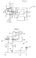
- a wind turbine W in Fig. 1 sits on a tower 1, a rotatable tower gondola 2, in which a generator 3 is housed, which is driven via a connecting shaft 4 of a rotor blades 6 equipped with rotor 5.
- Each rotor blade 6 is adjustable about the rotor blade axis within a predetermined angular range in order to bring the rotor blade into or out of the wind (pitching-out).
- the hydraulic cylinder 8 is controlled via a valve combination 9 from a pressure line 10 and into a tank line 11, which are connected via rotary feedthrough interfaces 14, for example on the shaft 4, to a pump 12 and a tank 13.
- the rotor blade position is permanently controlled to maintain a particular rotor speed.
- Rotor blade adjustments must be performed very sensitively and without abrupt delays and accelerations because the rotor blades are very expensive and delicate.
- the electro-hydraulic control device for rotor blade adjustment is housed in the rotor 5 and must, at least for adjustment from the Wndautark and operate maintenance-free.
- the hydraulic cylinder 8 is a differential cylinder having a piston rod 22 and a differential piston 21 which separates a piston side chamber 19 and a piston rod side chamber 20.
- a check valve R secured pressure line 10 of the accumulator 15, which is expediently a piston accumulator connected.
- a flow path 16 branches off to the piston-side chamber 19.
- a 2/2-way proportional valve seat V2 is arranged with a proportional magnet m2 in the valve combination 9, which in de-energized Condition by a spring assumes the shown, full passage position.
- This proportional seat valve V2 is a control valve, as indicated by the parallel lines adjacent to the valve symbol. Between the pressure line 10 and a branch 18 upstream of the proportional seat valve V2, a non-return valve 17 which blocks the pressure line 10 is provided. From the branch 18, a regenerative line 25 leads directly to the piston rod-side chamber 20, bypassing the proportional seat valve V2. Downstream of the proportional seat valve V2, a return line 24 to the tank line 11 is connected to a branch 23 of the flow path 16. In the return line 24, a 2/2-way proportional valve seat V1 is arranged with its proportional solenoid m3, which occupies the shut-off position shown in the de-energized state by a spring. Both proportional seat valves V1, V2 are characterized by a leak-free shut-off position. Suitably, the valves V1, V2 are formed as the off EP 0 955 472 A known.
- the rotor blade 6 By extending the piston rod 22, the rotor blade 6 ( Fig. 1 ), for example, put out of the wind, however, by retracting the piston rod 22 in the wind.
- the two proportional magnets m2, m3 are alternately driven by a higher-level control component, for example in the tower nacelle 2, to make a rotor blade adjustment, for example, the wind speed is a control parameter that is taken into account to achieve a constant rotor speed permanently.
- the procedure according to the regenerative principle ie, the ejected from the piston rod side chamber 20 pressure medium is fed via the proportional seat valve V2 in the piston-side chamber 19, so that the pressure accumulator 15 with blocking check valve R, if ever, only a small amount of pressure medium nach telephone needs.
- the proportional magnet m2 is left fully energized and the proportional magnet m3 energized as required, so that pressure medium from the piston-side chamber 19 flows into the tank line 11 and the pressure of the pressure accumulator 15 in the piston rod-side chamber 20 adjusted the piston until the proportional solenoid m3 is de-energized again.
- the proportional seat valve V2 is adjusted to its full passage position (as shown) until the piston 21 reaches its fully extended end position.
- Fig. 3 is the electro-hydraulic regenerative control device of Fig. 1 with regard to even faster response, for example in an emergency situation, extended.
- a bypass line leads to the branch 23 or to the piston-side chamber of the hydraulic cylinder 8.
- a bypass line is a 2/2-way black / white magnetic seat valve V3 with a black / white Magnets m1 arranged. This magnetic seat valve V3 is energized in the normal regenerative mode and in its shut-off position, so that it has no influence.
- the spring of the magnetic seat valve V3 pushes it into the passage position (as in FIG Figure 3 shown), so that pressure medium, for example from the pressure accumulator 15, or from the pump port, flows directly into the piston-side chamber, wherein the displaced from the piston rod-side chamber pressure medium is additionally introduced until the piston has reached its fully extended position.
- a check valve 26 is provided downstream of the Proportionalsitzventils V1, which blocks in the flow direction to Proportionalsitzventil V1.
- Fig. 4 is the electro-hydraulic regenerative control device of Fig. 3 further supplemented by additional security measures. Namely, there are further provided: a locking spring storage cylinder 32 with a locking pin 37 for mechanical Locking the rotor blade in the fully out of the wind position; a hedge 29 with a hydraulically releasable check valve 33; and a 3/2-way black and white magnetic seat valve V4 with a black and white magnet m4.
- the magnetic seat valve V4 is connected via a line 35 to a branch 34, for example, the inflow line 16, and via a line 36 to the tank line 10. From the magnetic seat valve V4 performs a working line 31 to the pressure side of the Arretierfeder umanzylinders 32. From the working line 31 branches off a pilot line 30 for unlocking the check valve 33 in Abströmweg 24 from.
- the magnetic seat valve V4 connects in the de-energized state, the working line 31 via the line 36 to the tank line 11, wherein it shuts off the line 35.
- the black / white magnet m4 is energized, so that the working line 31 from the pump line 10 is acted upon and retracted the Arretierfeder acknowledgedzylinder.
- the pressure in the working line 31 unlocks the check valve 33, so that if necessary, the pressure medium from the piston-side chamber 19 can flow as desired.
- the magnetic seat valve V3 switches to the passage position shown, so that the piston-side chamber 19 is acted upon and the piston rod is extended in order to set the rotor blade out of the wind.
- the magnetic seat valve V4 connects in now de-energized state (as in Fig. 4 shown), the working line 31 with the tank line 11, so that the pin 37 is extended and mechanically fixes the rotor blade, as soon as it is fully out of the wind. Since then the control line 30 is depressurized, the check valve 33 assumes its shut-off position, so that the piston in the hydraulic cylinder 8 is no longer able to move automatically.
- the inventive electrohydraulic regenerative control device allows a drastic cost reduction, for example by more than 50% compared to conventional solutions.
- the control device can operate at a pressure up to about 250 bar, so that a piston accumulator with a capacity of about 20 to 25 I is sufficient. This allows, for example, a rotor blade adjustment over approximately 90 ° from full in the wind to fully out of the wind within 10 seconds.
- With the permanent rotor blade position control which in some cases has only small angular ranges, positioning times in the range of only one second or less can be achieved.
- the 2/2-way proportional seat valves are commercially available and can be identical. Appropriately, they operate with a hydraulic pilot control for the seat valve closing member.
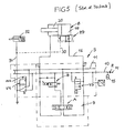
- the known electro-hydraulic regenerative control device S in Fig. 5 points next to some, for example, too Fig. 5 apparent components in the valve combination 9, a 4/3-way solenoid-gate valve A, to which the two chambers 19, 20 are connected separately.
- the chambers 19, 20 are shut off, whereby functionally necessary leakage occurs in the way slide valve.
- a 2/2-way proportional seat valve is provided, which is shown in the currentless state in its shut-off position.
- the safety device 29 for securing the piston-side chamber 19 is functionally necessary, because the leakage of the directional spool valve A also generates a pressure reduction in the tank line 11 in the neutral position.
- the directional control valve A must process at least in the discharge of the piston-side chamber 19 a high pressure medium throughput, ie have large passage cross-sections. The same applies to the proportional seat valve B.
Landscapes
- Engineering & Computer Science (AREA)
- Mechanical Engineering (AREA)
- General Engineering & Computer Science (AREA)
- Physics & Mathematics (AREA)
- Fluid Mechanics (AREA)
- Life Sciences & Earth Sciences (AREA)
- Sustainable Development (AREA)
- Sustainable Energy (AREA)
- Chemical & Material Sciences (AREA)
- Combustion & Propulsion (AREA)
- Wind Motors (AREA)
Claims (7)
- Dispositif de commande régénérateur électro-hydraulique (S) pour le réglage de pales de rotor d'une installation éolienne (W), comprenant un vérin hydraulique (8) double effet qui comporte un piston différentiel (21, 22) et dont les chambres (19, 20) du côté piston et du côté tige de piston peuvent être, en mode régénération, sélectivement, soit conjointement sollicitées en pression, soit fermées, soit déchargées en pression vers un réservoir (13), par l'intermédiaire d'une combinaison d'électrovannes (9) à partir d'une alimentation en pression commune (12, 10), la combinaison de vannes présentant au moins une vanne à siège proportionnelle à 2/2 voies (V2) au moins dans le chemin d'écoulement (16) vers la chambre (19) du côté piston, et l'alimentation en pression présentant en amont d'une vanne anti-retour (R) un raccordement de pompe prévu à une interface de passage rotatif (14) entre le rotor (5) comportant le dispositif de commande (S) et une nacelle rotative à tour (2) supportant le rotor et au moins un réservoir de pression (15) en aval de la vanne anti-retour (R), caractérisé en ce que la combinaison de vannes (9) ne comprend que deux vannes à siège proportionnelles à 2/2 voies (V1, V2) fonctionnellement séparées pour le réglage des pales, chacune avec une position de fermeture sans perte, dont l'une est disposée dans le chemin d'échappement (24) de la chambre (19) du côté piston au réservoir (13) et l'autre est disposée dans le chemin d'arrivée (16) du raccordement de pompe à la chambre (19) du côté piston et en aval d'une dérivation (18) d'une conduite régénératrice (25) menant directement du raccordement de pompe à la chambre (20) du côté tige de piston en contournant l'autre vanne à siège proportionnelle à 2/2 voies (V2).
- Dispositif de commande régénérateur électro-hydraulique suivant la revendication 1, caractérisé en ce que l'une des vannes à siège proportionnelles à 2/2 voies (V1) occupe la position de fermeture dans l'état hors tension et l'autre occupe la position de passage total dans l'état hors tension.
- Dispositif de commande régénérateur électro-hydraulique suivant la revendication 1, caractérisé en ce qu'une vanne anti-retour (17) fermant vers le raccordement de pompe est prévue entre le raccordement de pompe ou le réservoir de pression (15) et la dérivation (18).
- Dispositif de commande électro-hydraulique suivant la revendication 1, caractérisé en ce que l'accumulateur de pression (15) est un accumulateur de pression à piston.
- Dispositif de contrôle électro-hydraulique à régénération suivant la revendication 1, caractérisé en ce qu'une conduite de bipasse (28) jusqu'à la chambre (19) du côté piston est prévue entre la dérivation (18) et la chambre (20) du côté tige de piston, et qu'une vanne de secours à siège magnétique tout ou rien à 2/2 voies (V3) qui occupe dans l'état hors tension une position de passage est prévue dans la conduite de bipasse (28), laquelle vanne occupe une position de fermeture sans perte pour la chambre (19) du côté piston dans l'état d'alimentation en courant.
- Dispositif de commande régénérateur électro-hydraulique suivant l'une au moins des revendications précédentes, caractérisé en ce qu'une vanne à siège magnétique à 3/2 voies (V4) est disposée entre une conduite de travail (31) menant à un vérin accumulateur à ressort d'arrêt (32) et le raccord de pompe ou le réservoir, laquelle vanne relie la conduite de travail (31) au réservoir dans l'état hors tension, que la chambre (19) du côté piston est protégée dans la direction d'échappement par une vanne anti-retour (33) capable de verrouiller hydrauliquement la conduite de travail (31), et que la vanne à siège de secours magnétique tout ou rien à 2/2 voies (V3) et la vanne à siège magnétique à 3/2 voies (V4) sont alimentées en courant en mode régénération.
- Dispositif de commande régénérateur électro-hydraulique suivant la revendication 1, caractérisé en ce que les deux vannes à siège proportionnelles à 2/2 voies (V1, V2) présentent une construction commune avec leurs aimants proportionnels (m3, m2).
Applications Claiming Priority (2)
| Application Number | Priority Date | Filing Date | Title |
|---|---|---|---|
| DE20317749U DE20317749U1 (de) | 2003-11-18 | 2003-11-18 | Elektrohydraulische Regenerativ-Steuervorrichtung |
| DE20317749U | 2003-11-18 |
Publications (2)
| Publication Number | Publication Date |
|---|---|
| EP1533520A1 EP1533520A1 (fr) | 2005-05-25 |
| EP1533520B1 true EP1533520B1 (fr) | 2011-10-19 |
Family
ID=34399758
Family Applications (1)
| Application Number | Title | Priority Date | Filing Date |
|---|---|---|---|
| EP04018845A Expired - Fee Related EP1533520B1 (fr) | 2003-11-18 | 2004-08-09 | Système de réglage électrohydraulique régénérative de l'incidence des pales de turbine éolienne |
Country Status (4)
| Country | Link |
|---|---|
| EP (1) | EP1533520B1 (fr) |
| DE (1) | DE20317749U1 (fr) |
| DK (1) | DK1533520T3 (fr) |
| ES (1) | ES2375549T3 (fr) |
Cited By (1)
| Publication number | Priority date | Publication date | Assignee | Title |
|---|---|---|---|---|
| DE102021006222B3 (de) | 2021-12-16 | 2023-04-20 | Hydac International Gmbh | Pressenvorrichtung und 2/2-Wege-Proportional-Sitzventil |
Families Citing this family (16)
| Publication number | Priority date | Publication date | Assignee | Title |
|---|---|---|---|---|
| DE102006012008A1 (de) * | 2006-03-14 | 2007-09-20 | Robert Bosch Gmbh | Steuervorrichtung zur Rotorblattverstellung |
| ES2321252B1 (es) * | 2006-06-21 | 2011-02-14 | GAMESA INNOVATION & TECHNOLOGY, S.L. | Union rotativa para aerogeneradores. |
| AT505050B8 (de) * | 2007-04-13 | 2009-05-15 | Pessl Rudolf Ing | Windkraftanlage |
| WO2009064264A1 (fr) * | 2007-11-09 | 2009-05-22 | Moog Inc. | Actionneur électrohydraulique pour la commande du pas d'une pale d'une éolienne |
| WO2011116845A2 (fr) | 2010-03-26 | 2011-09-29 | Siemens Aktiengesellschaft | Eolienne à entraînement direct |
| CN102812242B (zh) * | 2010-03-26 | 2016-08-03 | 西门子公司 | 直驱型风力涡轮机、输送系统和构造直驱型风力涡轮机的方法 |
| CN102812236B (zh) * | 2010-03-26 | 2017-02-22 | 西门子公司 | 风力涡轮机和构造风力涡轮机的方法 |
| EP2392819B1 (fr) | 2010-05-31 | 2013-04-03 | HAWE Hydraulik SE | Dispositif de réglage rotatif hydroélectrique des pales de rotor sur le rotor d'une éolienne |
| US9068556B2 (en) | 2010-11-26 | 2015-06-30 | Vestas Wind Systems A/S | Pilot circuitry for controlling the emergency feathering of a wind turbine |
| CN102536660B (zh) * | 2010-11-26 | 2014-10-29 | 维斯塔斯风力系统有限公司 | 具有液压叶片变桨系统的风轮机 |
| CN102251915A (zh) * | 2011-06-24 | 2011-11-23 | 武汉大学 | 一种轴流式水轮机浆叶调节器 |
| EP2584192A1 (fr) * | 2011-10-19 | 2013-04-24 | Siemens Aktiengesellschaft | Dispositif de réglage de pas |
| EP2597209B1 (fr) * | 2011-11-23 | 2016-03-16 | HAWE Hydraulik SE | Système de réglage d'un dispositif de levage hydro-électronique |
| CN102536664A (zh) * | 2012-01-09 | 2012-07-04 | 青岛敏深风电科技有限公司 | 风力发电机气动变桨制动系统 |
| DK201270573A (en) * | 2012-02-01 | 2013-08-02 | Hydratech Ind Wind Power As | Hydraulic system primarily for pitch control |
| DE102017200756A1 (de) | 2017-01-18 | 2018-07-19 | Robert Bosch Gmbh | Nabe für eine Windenergieanlage, Windenergieanlage und Verfahren zur Herstellung einer Windenergieanlage |
Family Cites Families (7)
| Publication number | Priority date | Publication date | Assignee | Title |
|---|---|---|---|---|
| US4503673A (en) * | 1979-05-25 | 1985-03-12 | Charles Schachle | Wind power generating system |
| US5415076A (en) * | 1994-04-18 | 1995-05-16 | Caterpillar Inc. | Hydraulic system having a combined meter-out and regeneration valve assembly |
| FR2748296B1 (fr) * | 1996-05-06 | 1998-11-20 | Richer Bertrand Louis Isidore | Systeme de controle du calage des pales d'un aerogenerateur avec effet de reduction des charges dynamiques et extremes |
| US6457487B1 (en) * | 2001-05-02 | 2002-10-01 | Husco International, Inc. | Hydraulic system with three electrohydraulic valves for controlling fluid flow to a load |
| US6467264B1 (en) * | 2001-05-02 | 2002-10-22 | Husco International, Inc. | Hydraulic circuit with a return line metering valve and method of operation |
| DE20212459U1 (de) * | 2002-08-13 | 2003-12-24 | Hawe Hydraulik Gmbh & Co. Kg | Elektrohydraulischer Bremsmodul |
| DE20215838U1 (de) * | 2002-10-15 | 2004-02-26 | Hawe Hydraulik Gmbh & Co. Kg | Computerisierte elektrohydraulische Proportional-Steuervorrichtung |
-
2003
- 2003-11-18 DE DE20317749U patent/DE20317749U1/de not_active Expired - Lifetime
-
2004
- 2004-08-09 ES ES04018845T patent/ES2375549T3/es active Active
- 2004-08-09 EP EP04018845A patent/EP1533520B1/fr not_active Expired - Fee Related
- 2004-08-09 DK DK04018845.0T patent/DK1533520T3/da active
Cited By (1)
| Publication number | Priority date | Publication date | Assignee | Title |
|---|---|---|---|---|
| DE102021006222B3 (de) | 2021-12-16 | 2023-04-20 | Hydac International Gmbh | Pressenvorrichtung und 2/2-Wege-Proportional-Sitzventil |
Also Published As
| Publication number | Publication date |
|---|---|
| EP1533520A1 (fr) | 2005-05-25 |
| DE20317749U1 (de) | 2005-03-24 |
| DK1533520T3 (da) | 2012-02-06 |
| ES2375549T3 (es) | 2012-03-01 |
Similar Documents
| Publication | Publication Date | Title |
|---|---|---|
| EP1533520B1 (fr) | Système de réglage électrohydraulique régénérative de l'incidence des pales de turbine éolienne | |
| EP1985867B1 (fr) | Dispositif de réglage électrohydraulique pour un support de panneau solaire | |
| EP1835174B1 (fr) | Dispositif de commande destiné au réglage d'une pale de rotor | |
| EP1846807B1 (fr) | Vanne, en particulier vanne proportionnelle limitatrice de pression | |
| EP2840264B1 (fr) | Système d'actionnement à sécurité intégrée | |
| EP1369598B2 (fr) | Dispositif électro-hydraulique de commande de levage pour véhicules de manutention | |
| DE19514329A1 (de) | Hydraulisches System mit einer kombinierten Aus- bzw. Zumeß- und Regenerationsventilanordnung | |
| WO2012104046A1 (fr) | Dispositif de réglage hydraulique | |
| EP1635070A1 (fr) | Dispositif de contrôle électro-hydraulique | |
| DE2654366A1 (de) | Hydroventileinrichtung | |
| EP0054602A1 (fr) | Soupape d'arrêt contrôlée par son propre fluide | |
| WO2018108615A1 (fr) | Entraînement hydraulique à course rapide et course en charge | |
| DE2414020A1 (de) | Vorrichtung zur steuerung eines doppelt wirkenden hydraulikzylinders bei einem drehpflug | |
| EP0219052B1 (fr) | Dispositif de commande hydraulique | |
| EP2392819B1 (fr) | Dispositif de réglage rotatif hydroélectrique des pales de rotor sur le rotor d'une éolienne | |
| DE102004057739A1 (de) | Bremseinrichtung | |
| DE3233046A1 (de) | Elektrohydraulische steuervorrichtung | |
| DE102013216790A1 (de) | Schaltarmaturanordnung | |
| WO1995033136A1 (fr) | Systeme de regulation d'un dispositif de levage avec soupape de regulation | |
| DE3222106C2 (fr) | ||
| EP1574720B1 (fr) | Commande électro-hydraulique et méthode de sa déactivation | |
| EP3244072B1 (fr) | Système de soupapes hydrostatiques et dispositif de levage hydrostatique doté du système de soupapes | |
| DE10340506A1 (de) | Ventilanordnung und Hydraulikantrieb | |
| EP2535663B1 (fr) | Réflecteur solaire doté d'un dispositif de réglage hydraulique | |
| DE2638279A1 (de) | Steuerventil |
Legal Events
| Date | Code | Title | Description |
|---|---|---|---|
| PUAI | Public reference made under article 153(3) epc to a published international application that has entered the european phase |
Free format text: ORIGINAL CODE: 0009012 |
|
| AK | Designated contracting states |
Kind code of ref document: A1 Designated state(s): AT BE BG CH CY CZ DE DK EE ES FI FR GB GR HU IE IT LI LU MC NL PL PT RO SE SI SK TR |
|
| AX | Request for extension of the european patent |
Extension state: AL HR LT LV MK |
|
| 17P | Request for examination filed |
Effective date: 20050624 |
|
| AKX | Designation fees paid |
Designated state(s): DE DK ES |
|
| RAP1 | Party data changed (applicant data changed or rights of an application transferred) |
Owner name: HAWE HYDRAULIK SE |
|
| GRAP | Despatch of communication of intention to grant a patent |
Free format text: ORIGINAL CODE: EPIDOSNIGR1 |
|
| GRAS | Grant fee paid |
Free format text: ORIGINAL CODE: EPIDOSNIGR3 |
|
| GRAA | (expected) grant |
Free format text: ORIGINAL CODE: 0009210 |
|
| AK | Designated contracting states |
Kind code of ref document: B1 Designated state(s): DE DK ES |
|
| REG | Reference to a national code |
Ref country code: DE Ref legal event code: R081 Ref document number: 502004012990 Country of ref document: DE Owner name: HAWE HYDRAULIK SE, DE Free format text: FORMER OWNER: HAWE HYDRAULIK GMBH & CO. KG, 81673 MUENCHEN, DE |
|
| REG | Reference to a national code |
Ref country code: DE Ref legal event code: R096 Ref document number: 502004012990 Country of ref document: DE Effective date: 20111222 |
|
| REG | Reference to a national code |
Ref country code: DK Ref legal event code: T3 |
|
| REG | Reference to a national code |
Ref country code: ES Ref legal event code: FG2A Ref document number: 2375549 Country of ref document: ES Kind code of ref document: T3 Effective date: 20120301 |
|
| PLBE | No opposition filed within time limit |
Free format text: ORIGINAL CODE: 0009261 |
|
| STAA | Information on the status of an ep patent application or granted ep patent |
Free format text: STATUS: NO OPPOSITION FILED WITHIN TIME LIMIT |
|
| 26N | No opposition filed |
Effective date: 20120720 |
|
| REG | Reference to a national code |
Ref country code: DE Ref legal event code: R097 Ref document number: 502004012990 Country of ref document: DE Effective date: 20120720 |
|
| REG | Reference to a national code |
Ref country code: DK Ref legal event code: EBP |
|
| PG25 | Lapsed in a contracting state [announced via postgrant information from national office to epo] |
Ref country code: DK Free format text: LAPSE BECAUSE OF NON-PAYMENT OF DUE FEES Effective date: 20120831 |
|
| REG | Reference to a national code |
Ref country code: DE Ref legal event code: R082 Ref document number: 502004012990 Country of ref document: DE Representative=s name: GROSSE, SCHUMACHER, KNAUER, VON HIRSCHHAUSEN, DE |
|
| PGFP | Annual fee paid to national office [announced via postgrant information from national office to epo] |
Ref country code: ES Payment date: 20160819 Year of fee payment: 13 |
|
| REG | Reference to a national code |
Ref country code: DE Ref legal event code: R082 Ref document number: 502004012990 Country of ref document: DE Representative=s name: GROSSE, SCHUMACHER, KNAUER, VON HIRSCHHAUSEN, DE Ref country code: DE Ref legal event code: R081 Ref document number: 502004012990 Country of ref document: DE Owner name: HAWE HYDRAULIK SE, DE Free format text: FORMER OWNER: HAWE HYDRAULIK SE, 81673 MUENCHEN, DE |
|
| REG | Reference to a national code |
Ref country code: ES Ref legal event code: FD2A Effective date: 20181029 |
|
| PGFP | Annual fee paid to national office [announced via postgrant information from national office to epo] |
Ref country code: DE Payment date: 20180828 Year of fee payment: 15 |
|
| PG25 | Lapsed in a contracting state [announced via postgrant information from national office to epo] |
Ref country code: ES Free format text: LAPSE BECAUSE OF NON-PAYMENT OF DUE FEES Effective date: 20170810 |
|
| REG | Reference to a national code |
Ref country code: DE Ref legal event code: R119 Ref document number: 502004012990 Country of ref document: DE |
|
| PG25 | Lapsed in a contracting state [announced via postgrant information from national office to epo] |
Ref country code: DE Free format text: LAPSE BECAUSE OF NON-PAYMENT OF DUE FEES Effective date: 20200303 |