EP1533480A2 - Hot gas path component with mesh and turbulated cooling - Google Patents
Hot gas path component with mesh and turbulated cooling Download PDFInfo
- Publication number
- EP1533480A2 EP1533480A2 EP04255645A EP04255645A EP1533480A2 EP 1533480 A2 EP1533480 A2 EP 1533480A2 EP 04255645 A EP04255645 A EP 04255645A EP 04255645 A EP04255645 A EP 04255645A EP 1533480 A2 EP1533480 A2 EP 1533480A2
- Authority
- EP
- European Patent Office
- Prior art keywords
- turbulators
- component
- wall
- pins
- cooling
- Prior art date
- Legal status (The legal status is an assumption and is not a legal conclusion. Google has not performed a legal analysis and makes no representation as to the accuracy of the status listed.)
- Withdrawn
Links
Images


Classifications
-
- F—MECHANICAL ENGINEERING; LIGHTING; HEATING; WEAPONS; BLASTING
- F01—MACHINES OR ENGINES IN GENERAL; ENGINE PLANTS IN GENERAL; STEAM ENGINES
- F01D—NON-POSITIVE DISPLACEMENT MACHINES OR ENGINES, e.g. STEAM TURBINES
- F01D5/00—Blades; Blade-carrying members; Heating, heat-insulating, cooling or antivibration means on the blades or the members
- F01D5/12—Blades
- F01D5/14—Form or construction
- F01D5/20—Specially-shaped blade tips to seal space between tips and stator
-
- F—MECHANICAL ENGINEERING; LIGHTING; HEATING; WEAPONS; BLASTING
- F01—MACHINES OR ENGINES IN GENERAL; ENGINE PLANTS IN GENERAL; STEAM ENGINES
- F01D—NON-POSITIVE DISPLACEMENT MACHINES OR ENGINES, e.g. STEAM TURBINES
- F01D5/00—Blades; Blade-carrying members; Heating, heat-insulating, cooling or antivibration means on the blades or the members
- F01D5/12—Blades
- F01D5/14—Form or construction
- F01D5/18—Hollow blades, i.e. blades with cooling or heating channels or cavities; Heating, heat-insulating or cooling means on blades
- F01D5/187—Convection cooling
-
- F—MECHANICAL ENGINEERING; LIGHTING; HEATING; WEAPONS; BLASTING
- F05—INDEXING SCHEMES RELATING TO ENGINES OR PUMPS IN VARIOUS SUBCLASSES OF CLASSES F01-F04
- F05D—INDEXING SCHEME FOR ASPECTS RELATING TO NON-POSITIVE-DISPLACEMENT MACHINES OR ENGINES, GAS-TURBINES OR JET-PROPULSION PLANTS
- F05D2260/00—Function
- F05D2260/20—Heat transfer, e.g. cooling
- F05D2260/221—Improvement of heat transfer
- F05D2260/2212—Improvement of heat transfer by creating turbulence
-
- F—MECHANICAL ENGINEERING; LIGHTING; HEATING; WEAPONS; BLASTING
- F05—INDEXING SCHEMES RELATING TO ENGINES OR PUMPS IN VARIOUS SUBCLASSES OF CLASSES F01-F04
- F05D—INDEXING SCHEME FOR ASPECTS RELATING TO NON-POSITIVE-DISPLACEMENT MACHINES OR ENGINES, GAS-TURBINES OR JET-PROPULSION PLANTS
- F05D2260/00—Function
- F05D2260/20—Heat transfer, e.g. cooling
- F05D2260/221—Improvement of heat transfer
- F05D2260/2214—Improvement of heat transfer by increasing the heat transfer surface
- F05D2260/22141—Improvement of heat transfer by increasing the heat transfer surface using fins or ribs
-
- Y—GENERAL TAGGING OF NEW TECHNOLOGICAL DEVELOPMENTS; GENERAL TAGGING OF CROSS-SECTIONAL TECHNOLOGIES SPANNING OVER SEVERAL SECTIONS OF THE IPC; TECHNICAL SUBJECTS COVERED BY FORMER USPC CROSS-REFERENCE ART COLLECTIONS [XRACs] AND DIGESTS
- Y02—TECHNOLOGIES OR APPLICATIONS FOR MITIGATION OR ADAPTATION AGAINST CLIMATE CHANGE
- Y02T—CLIMATE CHANGE MITIGATION TECHNOLOGIES RELATED TO TRANSPORTATION
- Y02T50/00—Aeronautics or air transport
- Y02T50/60—Efficient propulsion technologies, e.g. for aircraft
Definitions
- the invention relates generally to hot gas path components for turbine assemblies and, more particularly, to synergistic approaches to cool the hot gas path components.
- Exemplary gas turbine engines are used for aircraft or stationary power applications, and engine efficiency is a key design criteria for both applications.
- the efficiency of gas turbine engines improves with increased temperature of the combustion gas flow.
- a limiting factor in the gas flow temperature is the high temperature capability of the various hot gas path components, such as the turbine stator and rotor airfoils.
- Stator airfoils are also known as vanes or nozzles
- rotor airfoils are also known as blades or buckets.
- a component in accordance with one embodiment of the present invention, includes at least one wall having an inner portion and an outer portion.
- a number of pins extend between the inner and outer portions of the wall.
- the pins define a mesh cooling arrangement having a number of flow channels.
- a number of turbulators are disposed on at least one of the inner and outer portions of the wall.
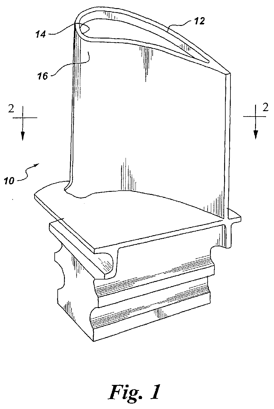
- a component 10 embodiment of the invention is described with reference to FIGS. 1-4.
- Exemplary components include hot gas path components, such as blades, vanes, end walls, and shrouds.
- the invention is equally applicable to other portions of the stator and rotor assemblies, as well as to other hot sections such as after-burners.
- the invention applies to various size and application gas turbines, such as aircraft engines and land-based power turbines.
- Conventional hot gas components are well known, as are mesh cooled hot gas path components.
- the component 10 shown is purely exemplary, and the invention is not limited to any particular component type. As shown, for example in FIGS. 1 and 2, the component 10 has at least one wall 12 having an inner portion 14 and an outer portion 16. As shown for example in FIGS.
- the component 10 further includes a number of pins 18 that extend between the inner and outer portions 14, 16 of the component wall 12.
- the pins define a mesh cooling arrangement 20 that includes a number of flow channels 22.
- Exemplary pin shapes are rounded or sharp, depending on the manufacturing method. Exemplary pin shapes include cylindrical and rounded diamonds. The shape may be selected, in part, to obtain a more directional cooling flow, for example to enhance interaction with the other cooling enhancements, such as turbulators, which are discussed below. Investment casting produces a rounded pin, whereas sharper corners result from fabrication methods.
- the component 10 also includes a number of turbulators 36 disposed on at least one of the inner and outer portions 14, 16 of the component wall 12, as shown for example in FIGS. 3 and 4. According to three particular embodiments, the turbulators 36 are formed on the inner portion 14 of the wall 12, on the outer portion 16 of the wall 12, and on both the inner and outer portions 14, 16 of the wall 12.
- the pins 18 are characterized by a height-to-diameter ratio of about less than or equal to two H/D ⁇ 2.0, and more particularly, by a height-to-diameter ratio of about less than one (H/D ⁇ 1.0), and still more particularly by a height-to-diameter ratio within a range of about 0.1 to about 0.3 (0.1 ⁇ H/D ⁇ 0.3).
- the pins 18 define a mesh cooling arrangement 20 (or "flow network mesh') with an overall blockage of about forty percent (40%) or greater.
- Blockage in this case refers to the percentage of the otherwise open flow channel cross-section area that is now occupied by the pins.
- exemplary circular pins are cylinders that extend between the inner and outer portions 14, 16 of the component wall 12.
- Other examples of low pressure loss pins include oval and elliptical pins.
- circular pins 18 are also desirable from an ease of manufacturing standpoint.
- FIG. 3 illustrates a transverse turbulator arrangement.
- the turbulators 36 extend between respective pairs of pins 18 in a direction transverse 38 to a cooling flow 40.
- the turbulators 36 may also be arranged in an angled configuration.
- FIG.5 shows turbulators 36 that extend between respective pairs of pins 18 and are oriented at an angle 42 relative to a cooling flow 40.
- FIG. 6 illustrates an exemplary arrangement of "alternating segmented" turbulators 36, for which a first subset 44 of turbulators 36 extend between respective pairs of pins 18 and are oriented at an angle 42 relative to a cooling flow 40.
- a second subset 46 of turbulators 36 extend between respective pairs of pins 18 and are oriented at a second angle 62 relative to the cooling flow 40.
- the first and second angles 42, 62 intersect.
- intersecting angles it is meant that the respective turbulators 36 in the first and second subsets 44 are not parallel.
- the respective turbulators 36 in the first subset 44 are oriented relative to the turbulators 36 in the second subset 46, such that they would intersect with their counterparts in the second subset 46 if they were long enough to do so.
- the precise relative orientation of members of the first and second subsets 44, 46 of turbulators 36 will vary based on the spacing between the pins 18, for example.
- a chevron turbulator embodiment is described with reference to FIG. 7.
- respective pairs of turbulators 36 form chevron turbulators 48 on the respective one of the inner and outer portions 14, 16 of the component wall 12.
- the chevron turbulators 48 are segmented chevron turbulators. Segmentation corresponds to an open apex 56, as shown in FIG. 7. Beneficially, segmentation, by providing an open apex 56, generates more effective fluid vortices. Convection along the angled direction of the turbulator segments 36 induces a kind of secondary vortical motion that is highly effective in thermal enhancements.
- each of the chevron turbulators 48 has an apex 56 oriented upstream relative to the cooling flow 40.
- Other arrangements include at least one chevron turbulator 48 with an apex 56 oriented downstream relative to the cooling flow 40.
- the relatively dense segmented chevron pattern of FIG. 7 is purely exemplary, and less dense segmented patterns are also embraced by the invention.
- Integrating a segmented chevron turbulator arrangement in a mesh cooling arrangement provides unique thermal enhancements.
- the cooling flow 40 is accelerated through the gaps between neighboring pins 18, and the accelerated cooling flow then interacts with the open apex portion 56 of the chevron turbulator 48 to generate mixing and convecting vortices (not shown).
- the chevron turbulators 48 enhance the interaction of the cooling flow with the downstream surface areas 58 of the pins 18. As a result of these synergies, the heat transfer is enhanced.
- the component 10 also includes a number of dimples 24 located in at least one of the inner and outer portions 14, 16 of the component wall 12.
- the dimples 24 are formed in the inner portion 14 of the wall 12, in the outer portion 16 of the wall 12, and in both the inner and outer portions 14, 16 of wall 12.
- Exemplary dimples 24 have a center depth of about 0.010 to about 0.030 inches and a surface diameter of about 0.010 to about 0.12 inches, for typical aircraft engine applications.
- exemplary dimples have a center depth of about 0.010 to about 0.060 inches and a surface diameter of about 0.010 to about 0.250 inches.
- the dimples 24 may be formed in a number of shapes.
- the dimples 24 are concave and, more particularly, are hemispherical or hemispherical sections.
- Another exemplary dimple shape is a cone shape, including both a full or a truncated inverted cone.
- the dimples 24 set up fluid vortices in the cooling flow, which causes mixing near the component wall 12, thereby enhancing the heat transfer at the wall 12, as well as on the pin surfaces.
- the dimples 24 also increase surface area to help compensate for the area covered by the pins 18. In this manner, the present invention leverages different thermal enhancements in a synergistic approach.
- FIG. 9 is a longitudinal sectional view of an embodiment of the mesh cooling arrangement taken along line 9-9 of FIG. 8.
- the dimples 24 are located in the outer portion 16 of the wall 12, as shown. More particularly, at least one coating 34 is disposed on the outer portion 16 of the wall 12.
- An exemplary coating 34 is a thermal barrier coating 34.
- each of the dimples 24 shown extends through the outer portion 16 of the wall 12 to form respective cooling holes 32, and each of the cooling holes 32 shown is at least partially covered by the coating 34.
- the dimples 24 provide film cooling for the component wall 12. More particularly, the dimples that extend through the outer portion 16 of the wall to form cooling holes 32 provide transpiration cooling, whereas the dimples 24 that do not extend through the outer portion of the wall (not expressly shown) provide convection.
- dimples 24 can be formed in either the inner or outer portions 14, 16 of the component wall 12 or in both the inner and outer portions 14, 16 of the wall 12, as noted above.
- the dimples 24 can be formed of varying depth and/or diameter, such that some, all or none of the dimples extend through the respective inner and outer portions 14, 16 of the component wall 12. Where the dimples 24 extend through the respective inner or outer portion 14, 16 of the wall 12, they form cooling holes 32, providing transpiration cooling for the component wall 12. Where the dimples 24 do not extend through the respective inner or outer portion 14, 16 of the wall 12, they provide convection to help cool the component wall 12.
Landscapes
- Engineering & Computer Science (AREA)
- Mechanical Engineering (AREA)
- General Engineering & Computer Science (AREA)
- Turbine Rotor Nozzle Sealing (AREA)
Abstract
Description
Claims (12)
- A component (10) comprising:at least one wall (12) having an inner portion (14) and an outer portion (16);a plurality of pins (18) extending between said inner and outer portions of said wall, wherein said pins define a mesh cooling arrangement (20) comprising a plurality of flow channels (22); anda plurality of turbulators (36) disposed on at least one of said inner and outer portions of said wall.
- The component (10) of Claim 1, wherein said pins (18) are characterized by a height-to-diameter ratio of about less than or equal to two (H/D ≤ 2.0).
- The component (10) of Claim 2, wherein said pins (18) are characterized by a height-to-diameter ratio of about less than one (H/D < 1.0).
- The component (10) of Claim 3, wherein said turbulators (36) are formed on only one of said inner and outer portions (14, 16) of said wall (12).
- The component (10) of Claim 3, wherein said turbulators (36) are formed on both of said inner and outer portions (14, 16) of said wall (12).
- The component (10) of Claim 3, wherein said turbulators (36) extend between respective pairs of said pins (18) in a direction transverse (38) to a cooling flow (40).
- The component (10) of Claim 3, wherein said turbulators (36) extend between respective pairs of said pins (18) and are oriented at an angle (42, 62) relative to a cooling flow (40).
- The component (10) of Claim 3, wherein a first subset (44) of said turbulators (36) extend between respective pairs of said pins (18) and are oriented at a first angle (42) relative to a cooling flow (40), wherein a second subset (46) of said turbulators (36) extend between respective pairs of said pins and are oriented at a second angle (62) relative to the cooling flow, and wherein the first and second angles intersect.
- The component (10) of Claim 3, wherein respective pairs of turbulators (36) form chevron turbulators (48) on the respective one of said inner and outer portions (14, 16) of said wall (12).
- The component (10) of Claim 9, wherein at least one of said chevron turbulators (48) has an apex (56) oriented upstream relative to a cooling flow (40).
- The component (10) of Claim 10, wherein each of said chevron turbulators (48) has an apex (56) oriented upstream relative to a cooling flow (40).
- The component (10) of Claim 9, wherein at least one of said chevron turbulators (48) has an apex (56) oriented downstream relative to a cooling flow (40).
Applications Claiming Priority (2)
| Application Number | Priority Date | Filing Date | Title |
|---|---|---|---|
| US718003 | 2003-11-19 | ||
| US10/718,003 US6984102B2 (en) | 2003-11-19 | 2003-11-19 | Hot gas path component with mesh and turbulated cooling |
Publications (2)
| Publication Number | Publication Date |
|---|---|
| EP1533480A2 true EP1533480A2 (en) | 2005-05-25 |
| EP1533480A3 EP1533480A3 (en) | 2009-10-28 |
Family
ID=34435772
Family Applications (1)
| Application Number | Title | Priority Date | Filing Date |
|---|---|---|---|
| EP04255645A Withdrawn EP1533480A3 (en) | 2003-11-19 | 2004-09-16 | Hot gas path component with mesh and turbulated cooling |
Country Status (3)
| Country | Link |
|---|---|
| US (1) | US6984102B2 (en) |
| EP (1) | EP1533480A3 (en) |
| JP (1) | JP2005147130A (en) |
Cited By (4)
| Publication number | Priority date | Publication date | Assignee | Title |
|---|---|---|---|---|
| WO2017039568A1 (en) * | 2015-08-28 | 2017-03-09 | Siemens Aktiengesellschaft | Turbine airfoil cooling channel with fenced pedestals |
| EP2538026A3 (en) * | 2011-06-22 | 2017-12-27 | United Technologies Corporation | Cooling system for turbine airfoil including ice-cream-cone-shaped pedestals |
| CN108291449A (en) * | 2015-12-03 | 2018-07-17 | 西门子股份公司 | Component and method for fluid stream engine |
| EP3650647A1 (en) * | 2018-11-09 | 2020-05-13 | United Technologies Corporation | Article having cooling passage network with inter-row sub-passages |
Families Citing this family (75)
| Publication number | Priority date | Publication date | Assignee | Title |
|---|---|---|---|---|
| US7775053B2 (en) * | 2004-09-20 | 2010-08-17 | United Technologies Corporation | Heat transfer augmentation in a compact heat exchanger pedestal array |
| US7837440B2 (en) * | 2005-06-16 | 2010-11-23 | General Electric Company | Turbine bucket tip cap |
| US7513745B2 (en) * | 2006-03-24 | 2009-04-07 | United Technologies Corporation | Advanced turbulator arrangements for microcircuits |
| US7527475B1 (en) | 2006-08-11 | 2009-05-05 | Florida Turbine Technologies, Inc. | Turbine blade with a near-wall cooling circuit |
| US7544044B1 (en) | 2006-08-11 | 2009-06-09 | Florida Turbine Technologies, Inc. | Turbine airfoil with pedestal and turbulators cooling |
| US7625178B2 (en) * | 2006-08-30 | 2009-12-01 | Honeywell International Inc. | High effectiveness cooled turbine blade |
| JP4929097B2 (en) * | 2007-08-08 | 2012-05-09 | 株式会社日立製作所 | Gas turbine blade |
| JP4930276B2 (en) * | 2007-08-21 | 2012-05-16 | 株式会社Ihi | Internal cooling structure for high temperature parts |
| JP5029960B2 (en) * | 2008-01-15 | 2012-09-19 | 株式会社Ihi | Internal cooling structure for high temperature parts |
| US8167560B2 (en) * | 2009-03-03 | 2012-05-01 | Siemens Energy, Inc. | Turbine airfoil with an internal cooling system having enhanced vortex forming turbulators |
| US8109724B2 (en) * | 2009-03-26 | 2012-02-07 | United Technologies Corporation | Recessed metering standoffs for airfoil baffle |
| US8894367B2 (en) * | 2009-08-06 | 2014-11-25 | Siemens Energy, Inc. | Compound cooling flow turbulator for turbine component |
| US9334741B2 (en) * | 2010-04-22 | 2016-05-10 | Siemens Energy, Inc. | Discreetly defined porous wall structure for transpirational cooling |
| US8894363B2 (en) | 2011-02-09 | 2014-11-25 | Siemens Energy, Inc. | Cooling module design and method for cooling components of a gas turbine system |
| US8905713B2 (en) | 2010-05-28 | 2014-12-09 | General Electric Company | Articles which include chevron film cooling holes, and related processes |
| US8714926B2 (en) | 2010-09-17 | 2014-05-06 | Siemens Energy, Inc. | Turbine component cooling channel mesh with intersection chambers |
| US9017027B2 (en) | 2011-01-06 | 2015-04-28 | Siemens Energy, Inc. | Component having cooling channel with hourglass cross section |
| US8764394B2 (en) | 2011-01-06 | 2014-07-01 | Siemens Energy, Inc. | Component cooling channel |
| US8882448B2 (en) | 2011-09-09 | 2014-11-11 | Siemens Aktiengesellshaft | Cooling system in a turbine airfoil assembly including zigzag cooling passages interconnected with radial passageways |
| US8840363B2 (en) | 2011-09-09 | 2014-09-23 | Siemens Energy, Inc. | Trailing edge cooling system in a turbine airfoil assembly |
| US8840371B2 (en) * | 2011-10-07 | 2014-09-23 | General Electric Company | Methods and systems for use in regulating a temperature of components |
| US8858159B2 (en) | 2011-10-28 | 2014-10-14 | United Technologies Corporation | Gas turbine engine component having wavy cooling channels with pedestals |
| US9422815B2 (en) | 2012-02-15 | 2016-08-23 | United Technologies Corporation | Gas turbine engine component with compound cusp cooling configuration |
| US8572983B2 (en) | 2012-02-15 | 2013-11-05 | United Technologies Corporation | Gas turbine engine component with impingement and diffusive cooling |
| US8683814B2 (en) | 2012-02-15 | 2014-04-01 | United Technologies Corporation | Gas turbine engine component with impingement and lobed cooling hole |
| US9416665B2 (en) | 2012-02-15 | 2016-08-16 | United Technologies Corporation | Cooling hole with enhanced flow attachment |
| US9284844B2 (en) | 2012-02-15 | 2016-03-15 | United Technologies Corporation | Gas turbine engine component with cusped cooling hole |
| US8850828B2 (en) | 2012-02-15 | 2014-10-07 | United Technologies Corporation | Cooling hole with curved metering section |
| US8689568B2 (en) | 2012-02-15 | 2014-04-08 | United Technologies Corporation | Cooling hole with thermo-mechanical fatigue resistance |
| US9416971B2 (en) | 2012-02-15 | 2016-08-16 | United Technologies Corporation | Multiple diffusing cooling hole |
| US9598979B2 (en) | 2012-02-15 | 2017-03-21 | United Technologies Corporation | Manufacturing methods for multi-lobed cooling holes |
| US9273560B2 (en) | 2012-02-15 | 2016-03-01 | United Technologies Corporation | Gas turbine engine component with multi-lobed cooling hole |
| US8584470B2 (en) | 2012-02-15 | 2013-11-19 | United Technologies Corporation | Tri-lobed cooling hole and method of manufacture |
| US8707713B2 (en) | 2012-02-15 | 2014-04-29 | United Technologies Corporation | Cooling hole with crenellation features |
| US9279330B2 (en) | 2012-02-15 | 2016-03-08 | United Technologies Corporation | Gas turbine engine component with converging/diverging cooling passage |
| US9482100B2 (en) | 2012-02-15 | 2016-11-01 | United Technologies Corporation | Multi-lobed cooling hole |
| US9410435B2 (en) | 2012-02-15 | 2016-08-09 | United Technologies Corporation | Gas turbine engine component with diffusive cooling hole |
| US8683813B2 (en) | 2012-02-15 | 2014-04-01 | United Technologies Corporation | Multi-lobed cooling hole and method of manufacture |
| US9024226B2 (en) | 2012-02-15 | 2015-05-05 | United Technologies Corporation | EDM method for multi-lobed cooling hole |
| US8763402B2 (en) | 2012-02-15 | 2014-07-01 | United Technologies Corporation | Multi-lobed cooling hole and method of manufacture |
| US10422230B2 (en) | 2012-02-15 | 2019-09-24 | United Technologies Corporation | Cooling hole with curved metering section |
| US8733111B2 (en) | 2012-02-15 | 2014-05-27 | United Technologies Corporation | Cooling hole with asymmetric diffuser |
| US8522558B1 (en) | 2012-02-15 | 2013-09-03 | United Technologies Corporation | Multi-lobed cooling hole array |
| US8920122B2 (en) | 2012-03-12 | 2014-12-30 | Siemens Energy, Inc. | Turbine airfoil with an internal cooling system having vortex forming turbulators |
| US20130243575A1 (en) | 2012-03-13 | 2013-09-19 | United Technologies Corporation | Cooling pedestal array |
| US8910378B2 (en) * | 2012-05-01 | 2014-12-16 | United Technologies Corporation | Method for working of combustor float wall panels |
| JP5360265B2 (en) * | 2012-06-08 | 2013-12-04 | 株式会社Ihi | Internal cooling structure for high temperature parts |
| CN104508247B (en) * | 2012-08-06 | 2017-05-31 | 通用电气公司 | Turbine airfoil and manufacturing method thereof |
| US9995148B2 (en) | 2012-10-04 | 2018-06-12 | General Electric Company | Method and apparatus for cooling gas turbine and rotor blades |
| CN103075202A (en) * | 2013-01-15 | 2013-05-01 | 上海交通大学 | Impingement cooling structure with grid turbulence effect in turbine blade |
| US9850762B2 (en) | 2013-03-13 | 2017-12-26 | General Electric Company | Dust mitigation for turbine blade tip turns |
| US8985949B2 (en) | 2013-04-29 | 2015-03-24 | Siemens Aktiengesellschaft | Cooling system including wavy cooling chamber in a trailing edge portion of an airfoil assembly |
| WO2015023339A2 (en) * | 2013-05-23 | 2015-02-19 | United Technologies Corporation | Gas turbine engine combustor liner panel |
| US10427213B2 (en) | 2013-07-31 | 2019-10-01 | General Electric Company | Turbine blade with sectioned pins and method of making same |
| US9695696B2 (en) | 2013-07-31 | 2017-07-04 | General Electric Company | Turbine blade with sectioned pins |
| US9500093B2 (en) * | 2013-09-26 | 2016-11-22 | Pratt & Whitney Canada Corp. | Internally cooled airfoil |
| US9133716B2 (en) * | 2013-12-02 | 2015-09-15 | Siemens Energy, Inc. | Turbine endwall with micro-circuit cooling |
| EP2949871B1 (en) * | 2014-05-07 | 2017-03-01 | United Technologies Corporation | Variable vane segment |
| US10364684B2 (en) | 2014-05-29 | 2019-07-30 | General Electric Company | Fastback vorticor pin |
| US9957816B2 (en) | 2014-05-29 | 2018-05-01 | General Electric Company | Angled impingement insert |
| US10422235B2 (en) | 2014-05-29 | 2019-09-24 | General Electric Company | Angled impingement inserts with cooling features |
| CA2950011C (en) | 2014-05-29 | 2020-01-28 | General Electric Company | Fastback turbulator |
| EP3149284A2 (en) | 2014-05-29 | 2017-04-05 | General Electric Company | Engine components with impingement cooling features |
| US10280785B2 (en) | 2014-10-31 | 2019-05-07 | General Electric Company | Shroud assembly for a turbine engine |
| US10233775B2 (en) | 2014-10-31 | 2019-03-19 | General Electric Company | Engine component for a gas turbine engine |
| KR101699887B1 (en) * | 2015-07-16 | 2017-01-25 | 부산대학교 산학협력단 | Gas turbine blade with pin-fin and rib turbulator between inner and outer walls |
| US10174620B2 (en) | 2015-10-15 | 2019-01-08 | General Electric Company | Turbine blade |
| WO2017095438A1 (en) * | 2015-12-04 | 2017-06-08 | Siemens Aktiengesellschaft | Turbine airfoil with biased trailing edge cooling arrangement |
| US11193386B2 (en) | 2016-05-18 | 2021-12-07 | Raytheon Technologies Corporation | Shaped cooling passages for turbine blade outer air seal |
| US10344619B2 (en) | 2016-07-08 | 2019-07-09 | United Technologies Corporation | Cooling system for a gaspath component of a gas powered turbine |
| US10605092B2 (en) | 2016-07-11 | 2020-03-31 | United Technologies Corporation | Cooling hole with shaped meter |
| US10683762B2 (en) | 2016-07-12 | 2020-06-16 | Rolls-Royce North American Technologies Inc. | Gas engine component with cooling passages in wall |
| US10830058B2 (en) | 2016-11-30 | 2020-11-10 | Rolls-Royce Corporation | Turbine engine components with cooling features |
| EP3421721A1 (en) * | 2017-06-28 | 2019-01-02 | Siemens Aktiengesellschaft | A turbomachine component and method of manufacturing a turbomachine component |
| US10837316B2 (en) * | 2017-08-25 | 2020-11-17 | DOOSAN Heavy Industries Construction Co., LTD | High thermal response exhaust diffuser strut collar |
Family Cites Families (56)
| Publication number | Priority date | Publication date | Assignee | Title |
|---|---|---|---|---|
| US1848375A (en) * | 1929-04-27 | 1932-03-08 | Wellington W Muir | Radiator core for automobile cooling systems |
| US2938333A (en) * | 1957-03-18 | 1960-05-31 | Gen Motors Corp | Combustion chamber liner construction |
| US3229763A (en) * | 1963-07-16 | 1966-01-18 | Rosenblad Corp | Flexible plate heat exchangers with variable spacing |
| US3664928A (en) * | 1969-12-15 | 1972-05-23 | Aerojet General Co | Dimpled heat transfer walls for distillation apparatus |
| US3899882A (en) * | 1974-03-27 | 1975-08-19 | Westinghouse Electric Corp | Gas turbine combustor basket cooling |
| US4184326A (en) * | 1975-12-05 | 1980-01-22 | United Technologies Corporation | Louver construction for liner of gas turbine engine combustor |
| US4158949A (en) * | 1977-11-25 | 1979-06-26 | General Motors Corporation | Segmented annular combustor |
| US4407632A (en) * | 1981-06-26 | 1983-10-04 | United Technologies Corporation | Airfoil pedestaled trailing edge region cooling configuration |
| US4474532A (en) * | 1981-12-28 | 1984-10-02 | United Technologies Corporation | Coolable airfoil for a rotary machine |
| JPH06100432B2 (en) * | 1984-06-20 | 1994-12-12 | 株式会社日立製作所 | Heat transfer tube |
| JPS61280390A (en) | 1985-02-25 | 1986-12-10 | Hitachi Ltd | Heat exchanger and its manufacturing method |
| US4838031A (en) * | 1987-08-06 | 1989-06-13 | Avco Corporation | Internally cooled combustion chamber liner |
| US5667359A (en) * | 1988-08-24 | 1997-09-16 | United Technologies Corp. | Clearance control for the turbine of a gas turbine engine |
| JP3006174B2 (en) * | 1991-07-04 | 2000-02-07 | 株式会社日立製作所 | Member having a cooling passage inside |
| US5681144A (en) * | 1991-12-17 | 1997-10-28 | General Electric Company | Turbine blade having offset turbulators |
| US5695321A (en) * | 1991-12-17 | 1997-12-09 | General Electric Company | Turbine blade having variable configuration turbulators |
| US5370499A (en) * | 1992-02-03 | 1994-12-06 | General Electric Company | Film cooling of turbine airfoil wall using mesh cooling hole arrangement |
| US5690472A (en) * | 1992-02-03 | 1997-11-25 | General Electric Company | Internal cooling of turbine airfoil wall using mesh cooling hole arrangement |
| US5353865A (en) * | 1992-03-30 | 1994-10-11 | General Electric Company | Enhanced impingement cooled components |
| EP0590418B1 (en) * | 1992-10-02 | 1996-08-14 | Licentia Patent-Verwaltungs-GmbH | High voltage tube |
| US5651662A (en) * | 1992-10-29 | 1997-07-29 | General Electric Company | Film cooled wall |
| US5660525A (en) * | 1992-10-29 | 1997-08-26 | General Electric Company | Film cooled slotted wall |
| US5361828A (en) * | 1993-02-17 | 1994-11-08 | General Electric Company | Scaled heat transfer surface with protruding ramp surface turbulators |
| US5577555A (en) * | 1993-02-24 | 1996-11-26 | Hitachi, Ltd. | Heat exchanger |
| US5460002A (en) * | 1993-05-21 | 1995-10-24 | General Electric Company | Catalytically-and aerodynamically-assisted liner for gas turbine combustors |
| JPH08110012A (en) | 1994-10-07 | 1996-04-30 | Hitachi Ltd | Combustor liner manufacturing method |
| US5421158A (en) * | 1994-10-21 | 1995-06-06 | General Electric Company | Segmented centerbody for a double annular combustor |
| US5536143A (en) * | 1995-03-31 | 1996-07-16 | General Electric Co. | Closed circuit steam cooled bucket |
| US5758503A (en) * | 1995-05-03 | 1998-06-02 | United Technologies Corporation | Gas turbine combustor |
| JP3297838B2 (en) | 1996-02-09 | 2002-07-02 | 株式会社日立製作所 | Heat transfer tube and method of manufacturing the same |
| US5724816A (en) * | 1996-04-10 | 1998-03-10 | General Electric Company | Combustor for a gas turbine with cooling structure |
| US5933699A (en) * | 1996-06-24 | 1999-08-03 | General Electric Company | Method of making double-walled turbine components from pre-consolidated assemblies |
| US5822853A (en) * | 1996-06-24 | 1998-10-20 | General Electric Company | Method for making cylindrical structures with cooling channels |
| US5975850A (en) * | 1996-12-23 | 1999-11-02 | General Electric Company | Turbulated cooling passages for turbine blades |
| US5797726A (en) * | 1997-01-03 | 1998-08-25 | General Electric Company | Turbulator configuration for cooling passages or rotor blade in a gas turbine engine |
| US5738493A (en) * | 1997-01-03 | 1998-04-14 | General Electric Company | Turbulator configuration for cooling passages of an airfoil in a gas turbine engine |
| GB2328011A (en) * | 1997-08-05 | 1999-02-10 | Europ Gas Turbines Ltd | Combustor for gas or liquid fuelled turbine |
| US5931638A (en) * | 1997-08-07 | 1999-08-03 | United Technologies Corporation | Turbomachinery airfoil with optimized heat transfer |
| US6098397A (en) * | 1998-06-08 | 2000-08-08 | Caterpillar Inc. | Combustor for a low-emissions gas turbine engine |
| US6237344B1 (en) * | 1998-07-20 | 2001-05-29 | General Electric Company | Dimpled impingement baffle |
| US6468669B1 (en) * | 1999-05-03 | 2002-10-22 | General Electric Company | Article having turbulation and method of providing turbulation on an article |
| US6190120B1 (en) * | 1999-05-14 | 2001-02-20 | General Electric Co. | Partially turbulated trailing edge cooling passages for gas turbine nozzles |
| US6589600B1 (en) | 1999-06-30 | 2003-07-08 | General Electric Company | Turbine engine component having enhanced heat transfer characteristics and method for forming same |
| US6402470B1 (en) * | 1999-10-05 | 2002-06-11 | United Technologies Corporation | Method and apparatus for cooling a wall within a gas turbine engine |
| US6494044B1 (en) * | 1999-11-19 | 2002-12-17 | General Electric Company | Aerodynamic devices for enhancing sidepanel cooling on an impingement cooled transition duct and related method |
| US6331098B1 (en) | 1999-12-18 | 2001-12-18 | General Electric Company | Coriolis turbulator blade |
| US6412268B1 (en) * | 2000-04-06 | 2002-07-02 | General Electric Company | Cooling air recycling for gas turbine transition duct end frame and related method |
| US6334310B1 (en) * | 2000-06-02 | 2002-01-01 | General Electric Company | Fracture resistant support structure for a hula seal in a turbine combustor and related method |
| US6408629B1 (en) * | 2000-10-03 | 2002-06-25 | General Electric Company | Combustor liner having preferentially angled cooling holes |
| US6504274B2 (en) * | 2001-01-04 | 2003-01-07 | General Electric Company | Generator stator cooling design with concavity surfaces |
| US6526756B2 (en) * | 2001-02-14 | 2003-03-04 | General Electric Company | Method and apparatus for enhancing heat transfer in a combustor liner for a gas turbine |
| US6607355B2 (en) * | 2001-10-09 | 2003-08-19 | United Technologies Corporation | Turbine airfoil with enhanced heat transfer |
| US6644921B2 (en) | 2001-11-08 | 2003-11-11 | General Electric Company | Cooling passages and methods of fabrication |
| US6602047B1 (en) * | 2002-02-28 | 2003-08-05 | General Electric Company | Methods and apparatus for cooling gas turbine nozzles |
| US7022429B2 (en) | 2002-04-25 | 2006-04-04 | General Electric Company | Fluid passages for power generation equipment |
| US6808367B1 (en) * | 2003-06-09 | 2004-10-26 | Siemens Westinghouse Power Corporation | Cooling system for a turbine blade having a double outer wall |
-
2003
- 2003-11-19 US US10/718,003 patent/US6984102B2/en not_active Expired - Fee Related
-
2004
- 2004-09-16 EP EP04255645A patent/EP1533480A3/en not_active Withdrawn
- 2004-09-17 JP JP2004271148A patent/JP2005147130A/en active Pending
Cited By (8)
| Publication number | Priority date | Publication date | Assignee | Title |
|---|---|---|---|---|
| EP2538026A3 (en) * | 2011-06-22 | 2017-12-27 | United Technologies Corporation | Cooling system for turbine airfoil including ice-cream-cone-shaped pedestals |
| WO2017039568A1 (en) * | 2015-08-28 | 2017-03-09 | Siemens Aktiengesellschaft | Turbine airfoil cooling channel with fenced pedestals |
| CN108291449A (en) * | 2015-12-03 | 2018-07-17 | 西门子股份公司 | Component and method for fluid stream engine |
| CN108291449B (en) * | 2015-12-03 | 2020-08-18 | 西门子股份公司 | Component and method for a fluid flow engine |
| US11047242B2 (en) | 2015-12-03 | 2021-06-29 | Siemens Energy Global GmbH & Co. KG | Component for a fluid flow engine and method |
| EP3650647A1 (en) * | 2018-11-09 | 2020-05-13 | United Technologies Corporation | Article having cooling passage network with inter-row sub-passages |
| US11333023B2 (en) | 2018-11-09 | 2022-05-17 | Raytheon Technologies Corporation | Article having cooling passage network with inter-row sub-passages |
| EP4454782A3 (en) * | 2018-11-09 | 2025-03-05 | RTX Corporation | Article having cooling passage network with inter-row sub-passages |
Also Published As
| Publication number | Publication date |
|---|---|
| EP1533480A3 (en) | 2009-10-28 |
| US6984102B2 (en) | 2006-01-10 |
| US20050106020A1 (en) | 2005-05-19 |
| JP2005147130A (en) | 2005-06-09 |
Similar Documents
| Publication | Publication Date | Title |
|---|---|---|
| US6984102B2 (en) | Hot gas path component with mesh and turbulated cooling | |
| US7186084B2 (en) | Hot gas path component with mesh and dimpled cooling | |
| CA2415542C (en) | Crossover cooled airfoil trailing edge | |
| EP1637699B1 (en) | Offset coriolis turbulator blade | |
| EP0852284B1 (en) | Turbulator configuration for cooling passages of an airfoil in a gas turbine engine | |
| US8128366B2 (en) | Counter-vortex film cooling hole design | |
| US6607355B2 (en) | Turbine airfoil with enhanced heat transfer | |
| EP1068428B1 (en) | Apparatus for cooling a gas turbine airfoil and method of making same | |
| US6183197B1 (en) | Airfoil with reduced heat load | |
| EP3696377B1 (en) | Gas turbine engine component comprising a trailing edge cooling using angled impingement on surface enhanced with cast chevron arrangements | |
| US6997675B2 (en) | Turbulated hole configurations for turbine blades | |
| CN1550641A (en) | Method and apparatus for cooling an airfoil | |
| CA2456628A1 (en) | Microcircuit cooling for a turbine blade tip | |
| RU2285804C1 (en) | Member of gas-turbine engine and method of its manufacture | |
| US8882448B2 (en) | Cooling system in a turbine airfoil assembly including zigzag cooling passages interconnected with radial passageways | |
| EP1533481A2 (en) | Hot gas path component with a meshed and dimpled cooling structure | |
| US20210246810A1 (en) | Turbine nozzle segment and a turbinne nozzle comprising such a turbine nozzle segment | |
| JP2007231876A (en) | Blade cooling structure for gas turbine | |
| KR101866900B1 (en) | Gas turbine blade |
Legal Events
| Date | Code | Title | Description |
|---|---|---|---|
| PUAI | Public reference made under article 153(3) epc to a published international application that has entered the european phase |
Free format text: ORIGINAL CODE: 0009012 |
|
| AK | Designated contracting states |
Kind code of ref document: A2 Designated state(s): AT BE BG CH CY CZ DE DK EE ES FI FR GB GR HU IE IT LI LU MC NL PL PT RO SE SI SK TR |
|
| AX | Request for extension of the european patent |
Extension state: AL HR LT LV MK |
|
| PUAL | Search report despatched |
Free format text: ORIGINAL CODE: 0009013 |
|
| AK | Designated contracting states |
Kind code of ref document: A3 Designated state(s): AT BE BG CH CY CZ DE DK EE ES FI FR GB GR HU IE IT LI LU MC NL PL PT RO SE SI SK TR |
|
| AX | Request for extension of the european patent |
Extension state: AL HR LT LV MK |
|
| 17P | Request for examination filed |
Effective date: 20100428 |
|
| AKX | Designation fees paid |
Designated state(s): AT BE BG CH CY CZ DE DK EE ES FI FR GB GR HU IE IT LI LU MC NL PL PT RO SE SI SK TR |
|
| 17Q | First examination report despatched |
Effective date: 20100629 |
|
| STAA | Information on the status of an ep patent application or granted ep patent |
Free format text: STATUS: THE APPLICATION IS DEEMED TO BE WITHDRAWN |
|
| 18D | Application deemed to be withdrawn |
Effective date: 20101110 |