EP1533418A2 - Coating apparatus - Google Patents
Coating apparatus Download PDFInfo
- Publication number
- EP1533418A2 EP1533418A2 EP04104338A EP04104338A EP1533418A2 EP 1533418 A2 EP1533418 A2 EP 1533418A2 EP 04104338 A EP04104338 A EP 04104338A EP 04104338 A EP04104338 A EP 04104338A EP 1533418 A2 EP1533418 A2 EP 1533418A2
- Authority
- EP
- European Patent Office
- Prior art keywords
- application medium
- application
- degassing
- curtain
- applicator
- Prior art date
- Legal status (The legal status is an assumption and is not a legal conclusion. Google has not performed a legal analysis and makes no representation as to the accuracy of the status listed.)
- Ceased
Links
Images
Classifications
-
- D—TEXTILES; PAPER
- D21—PAPER-MAKING; PRODUCTION OF CELLULOSE
- D21H—PULP COMPOSITIONS; PREPARATION THEREOF NOT COVERED BY SUBCLASSES D21C OR D21D; IMPREGNATING OR COATING OF PAPER; TREATMENT OF FINISHED PAPER NOT COVERED BY CLASS B31 OR SUBCLASS D21G; PAPER NOT OTHERWISE PROVIDED FOR
- D21H23/00—Processes or apparatus for adding material to the pulp or to the paper
- D21H23/02—Processes or apparatus for adding material to the pulp or to the paper characterised by the manner in which substances are added
- D21H23/22—Addition to the formed paper
- D21H23/46—Pouring or allowing the fluid to flow in a continuous stream on to the surface, the entire stream being carried away by the paper
- D21H23/48—Curtain coaters
-
- B—PERFORMING OPERATIONS; TRANSPORTING
- B05—SPRAYING OR ATOMISING IN GENERAL; APPLYING FLUENT MATERIALS TO SURFACES, IN GENERAL
- B05C—APPARATUS FOR APPLYING FLUENT MATERIALS TO SURFACES, IN GENERAL
- B05C5/00—Apparatus in which liquid or other fluent material is projected, poured or allowed to flow on to the surface of the work
- B05C5/005—Curtain coaters
Definitions
- the invention relates to a device for one or both sides applying a highly viscous coating medium on a running surface, comprising a Curtain applicator and a degassing device for degassing the Order medium, wherein the curtain applicator the order medium as in im essentially gravity-induced moving curtain to the running surface and the surface when directly applied, the surface of a web especially paper or cardboard, and for indirect application, the surface a transfer element, preferably an applicator roll, which is the Application medium to the surface of the web emits.
- the surface quality of a coating layer depends significantly on the application medium. Gas bubbles present in the application medium appear on the surface of the application layer, where they burst and form uncovered areas on the material web. One of the reasons for this is the requirement for gas-free order media.
- the invention has the object of a device of the type mentioned To improve that in the future, even highly viscous order media can be processed as free of bubbles as possible.
- the invention solves the problem by a device with the characterizing features of claim 1 and a method according to Claim 10.
- the device according to the invention has at least one additional Degassing device for degassing and / or venting of the application medium.
- the degassing performance of the device is significantly improved, so that the unwanted inclusion of gas bubbles in the application medium is avoided. Consequently, with such a degassed according to the invention the application medium Application layer on a high surface quality.
- the Degassing devices arranged one behind the other and / or parallel to each other be.
- the degassing be per se known vacuum degasser.
- the device may also include a pulsation damper to compensate for Have pressure fluctuations.
- a filter which is arranged in the supply line for the application medium immediately before the application nozzle. It filters out the unwanted deposits from the application medium.
- Such a filter acts as a kind of "police filter” and can be formed as a sieve or protective cage. It can be installed directly in the interior of the pipeline and can be retrofitted in existing systems.
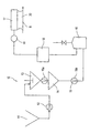
- the sole FIGURE shows a device 10 for applying a coating medium on a paper or board web B.
- the apparatus 10 has a container 11, in which the order medium is stored.
- the order medium is with a Entry pump 12 of a first degassing 13 is supplied.
- From there the application medium to a second degassing device 14.
- the two Degassing 13 and 14 is withdrawn from the application medium gas to when applied to a here only indicated to be coated web B a ensure optimum surface quality of the coating.
- the Degassing 13 and 14 vacuum degasser are the Degassing 13 and 14 vacuum degasser.
- a discharge pump 15a and 15b each guide the application medium from the Degassing 13 and 14 from. Pump 15b feeds the application medium first filter 16 too. Since the degassing 13 and 14 a very high Generate negative pressure, there is the danger of before the discharge pumps 15a and 15b Cavitations. The cavitations lead to pressure fluctuations, whereby the Surface quality of the coating is adversely affected. To avoid that, is at least the discharge pump 15b in a certain height difference of the Venting device 14 spaced. In practice, a minimum distance of proven two meters, but can also be larger than three meters.
- the filter 16 provides another contribution to Improvement of the surface quality of the coating.
- a pulsation damper 18 After the filter 16 flows through the application medium in the selected Embodiment, a pulsation damper 18.
- the pulsation damper 18 has the Task to compensate for pressure fluctuations in the device 10, and thus also to ensure a uniform application of the coating.
- a further filter 19 is arranged, which filters out of the pipe system between the filter 16 and the curtain applicator 17 originating deposits from the application medium.
- This filter 19 acts as the last safe link immediately before the commissioned work. From the filter 19 now passes the degassed and held free from impurities application medium finally to the curtain applicator 17, where it can be applied in the form of a closed curtain 20 either indirectly to an applicator roll, which emits the application medium to the surface of the material web to be coated, or the curtain 20 is applied directly (as also shown) directly to the surface of the material web B to be coated.
- the lines between the filter 16 and the curtain applicator 17 are arranged upwardly ascending. In this way, gas can be better discharged from the lines between the filter 16 and applicator 17. The gas accumulates in the lines after the device 10 has been emptied and must therefore be removed when starting the device 10, so that a satisfactory surface quality of the order is achieved.
Landscapes
- Coating Apparatus (AREA)
- Application Of Or Painting With Fluid Materials (AREA)
- Paper (AREA)
Abstract
Die Erfindung betrifft eine Vorrichtung (10) zum ein- oder beidseitigen Auftragen eines
flüssigen oder pastösen Auftragsmediums auf eine laufende Oberfläche, aufweisend
ein Vorhangauftragswerk (17) und eine Entlüftungseinrichtung (13) zur Entlüftung des
Auftragsmediums, wobei das Vorhangauftragswerk (17) das Auftragsmedium als sich
im wesentlichen schwerkraftbedingt bewegenden Vorhang (20) an die laufende
Oberfläche abgibt, und die Oberfläche bei direktem Auftrag die Oberfläche einer
Materialbahn, insbesondere aus Papier oder Karton ist, und bei indirektem Auftrag die
Oberfläche eines Übertragungselements, vorzugsweise eine Auftragswalze ist,
welches das Auftragsmedium an die Oberfläche der Materialbahn abgibt. Die
Erfindung hat die Aufgabe auch bei hoch viskosen Auftragsmedien eine möglichst
blasenfreie Beschichtung sicherzustellen. Deshalb weist die Vorrichtung (10)
erfindungsgemäß mindestens eine zusätzliche Entlüftungseinrichtung (14) auf.

Description
Die Erfindung betrifft eine Vorrichtung zum ein- oder beidseitigen Auftragen eines hochviskosen Auftragsmediums auf eine laufende Oberfläche, aufweisend ein Vorhangauftragswerk und eine Entgasungseinrichtung zum Entgasen des Auftragsmediums, wobei das Vorhangauftragswerk das Auftragsmedium als sich im wesentlichen schwerkraftbedingt bewegenden Vorhang an die laufende Cberfläche abgibt, und die Oberfläche bei direktem Auftrag die Oberfläche einer Materialbahn insbesondere aus Papier oder Karton ist, und bei indirektem Auftrag die Oberfläche eines Übertragungselements, vorzugsweise eine Auftragswalze ist, welches das Auftragsmedium an die Oberfläche der Materialbahn abgibt.The invention relates to a device for one or both sides applying a highly viscous coating medium on a running surface, comprising a Curtain applicator and a degassing device for degassing the Order medium, wherein the curtain applicator the order medium as in im essentially gravity-induced moving curtain to the running surface and the surface when directly applied, the surface of a web especially paper or cardboard, and for indirect application, the surface a transfer element, preferably an applicator roll, which is the Application medium to the surface of the web emits.
Die Oberflächenqualität einer Auftragsschicht hängt wesentlich vom Auftragsmedium
ab. Im Auftragsmedium vorhandene Gasbläschen tauchen an der Oberfläche der
Auftragsschicht auf, wo sie zerplatzen und unbedeckte Stellen auf der Materialbahn
bilden.
Es besteht unter anderem deshalb die Forderung nach gasfreien Auftragsmedien.The surface quality of a coating layer depends significantly on the application medium. Gas bubbles present in the application medium appear on the surface of the application layer, where they burst and form uncovered areas on the material web.
One of the reasons for this is the requirement for gas-free order media.
Bei Auftragsmedien mit höherer Viskosität ergibt sich das Problem, dass im Auftragsmedium eingeschlossene Gasbläschen kaum noch aus dem Auftragsmedium entweichen können und somit zu Auftragsschichten mit hohen Rauhigkeiten führen.For coating media with higher viscosity, the problem arises that in Application medium trapped gas bubbles barely from the application medium can escape and thus lead to application layers with high roughness.
Die Erfindung hat die Aufgabe eine Vorrichtung der eingangs genannten Art dahingehend zu verbessern, dass zukünftig auch hoch viskose Auftragsmedien möglichst blasenfrei verarbeitet werden können.The invention has the object of a device of the type mentioned To improve that in the future, even highly viscous order media can be processed as free of bubbles as possible.
Die Erfindung löst die gestellte Aufgabe durch eine Vorrichtung mit den
kennzeichnenden Merkmalen des Anspruches 1 und einem Verfahren gemäß
Anspruch 10. Die Vorrichtung weist erfindungsgemäß mindestens eine zusätzliche
Entgasungseinrichtung zur Entgasung und/oder Entlüftung des Auftragsmediums auf.
Dadurch wird die Entgasungsleistung der Vorrichtung deutlich verbessert, so dass der
unerwünschte Einschluss von Gasbläschen im Auftragsmedium vermieden wird.
Folglich weist mit einem derart erfindungsgemäß entgasten Auftragsmedium die
Auftragsschicht eine hohe Oberflächenqualität auf.The invention solves the problem by a device with the
characterizing features of claim 1 and a method according to
Um die Entlüftungsleistung der Vorrichtung weiter zu verbessern, können die Entgasungseinrichtungen hintereinander und/oder parallel zueinander angeordnet sein.In order to further improve the venting performance of the device, the Degassing devices arranged one behind the other and / or parallel to each other be.
In einer bevorzugten Ausführungsform können wegen ihrer hohen Leistungsfähigkeit die Entgasungseinrichtungen an sich bekannte Vakuumentgaser sein.In a preferred embodiment, because of their high performance the degassing be per se known vacuum degasser.
Da die Engasungseinrichtungen einen sehr hohen Unterdruck erzeugen, können vor
einer das Auftragsmedium aus den Entgasungseinrichtungen abführenden
Austragspumpe Kavitationen und dadurch wiederum Gaseinschlüsse entstehen.
Um die unerwünschten Kavitationen und die damit verbundenen Schwankungen zu
vermeiden, ist es zweckmäßig die Austragspumpe in einer bestimmten
Höhendifferenz zwischen ihr und der Entgasungseinrichtung anzuordnen.
Bei größerer Höhendifferenz ergibt sich ein höherer hydrostatischer Druck, wodurch
die Kavitation sich verringert.
In der Praxis haben sich Höhendifferenzen von ca. zwei Metern bewährt, die aber
auch mehr als drei Meter betragen können.Since the Engasungseinrichtungen produce a very high negative pressure cavitation and thereby in turn gas pockets may arise before a discharge medium from the degassing discharge pump.
In order to avoid the unwanted cavitations and the associated fluctuations, it is expedient to arrange the discharge pump in a certain height difference between it and the degassing.
With a larger height difference, a higher hydrostatic pressure results, whereby the cavitation is reduced.
In practice, height differences of about two meters have been proven, but can also be more than three meters.
Die Vorrichtung kann außerdem einen Pulsationsdämpfer zum Ausgleich von Druckschwankungen aufweisen.The device may also include a pulsation damper to compensate for Have pressure fluctuations.
Im Laufe der Zeit sammeln sich im Rohrleitungssystem zwischen Filter und der
Auftragsdüse vom Auftragsmedium stammende Ablagerungen an. Diese
Ablagerungen können die Düse des Vorhangauftragswerks verstopfen. Deshalb ist es
sinnvoll einen zusätzlichen Filter vorzusehen, der in der Zuführleitung für das
Auftragsmedium unmittelbar vor der Auftragsdüse angeordnet ist. Er filtert die
unerwünschten Ablagerungen aus dem Auftragsmedium heraus.
Ein solcher Filter, wirkt quasi als "Polizeifilter" und ist als Sieb- oder Schutzkorb
ausbildbar. Er lässt sich direkt in das Innere der Rohrleitung einbauen und ist
nachrüstbar in bereits bestehenden Anlagen.Over time, deposits originating in the piping system between the filter and the application nozzle accumulate from the application medium. These deposits can clog the nozzle of the curtain applicator. Therefore, it is useful to provide an additional filter, which is arranged in the supply line for the application medium immediately before the application nozzle. It filters out the unwanted deposits from the application medium.
Such a filter acts as a kind of "police filter" and can be formed as a sieve or protective cage. It can be installed directly in the interior of the pipeline and can be retrofitted in existing systems.
Beim Anfahren der Vorrichtung befindet sich Gas bzw. Luft in den Leitungen der
Vorrichtung. Beim Befüllen der Vorrichtung mit dem Auftragsmedium kann sich Gas in
bestimmten Bereichen ansammeln, welches sich dann im Laufe des
Beschichtungsvorganges löst und zu den beschriebenen Qualitätseinbußen führt.
Deshalb ist es sinnvoll, wenn die Leitungen nach der Austragspumpe nach oben
aufsteigend angeordnet sind, damit das angesammelte Gas aus den Leitungen
ausgetragen werden kann.
Es versteht sich, dass Totzonen, wie T-Rohleitungsstücke, beispielsweise vor
Spülleitungen zu vermeiden sind.When starting the device is gas or air in the lines of the device. When filling the device with the application medium gas can accumulate in certain areas, which then dissolves in the course of the coating process and leads to the described loss of quality. Therefore, it is useful if the lines are arranged after the discharge pump upwards so that the accumulated gas can be discharged from the lines.
It is understood that dead zones, such as T-pipe pieces, for example, are to be avoided before flushing lines.
Nachfolgend wird ein Ausführungsbeispiel der erfindungsgemäßen Vorrichtung anhand der beiliegenden Zeichnung näher erläutert.Hereinafter, an embodiment of the device according to the invention explained in more detail with reference to the accompanying drawings.
Die einzige Figur zeigt eine Vorrichtung 10 zum Auftragen eines Auftragsmediums
auf eine Papier- oder Kartonbahn B. Die Vorrichtung 10 weist einen Behälter 11 auf,
in dem das Auftragsmedium bevorratet wird. Das Auftragsmedium wird mit einer
Eintragspumpe 12 einer ersten Entgasungseinrichtung 13 zugeführt. Von dort gelangt
das Auftragsmedium zu einer zweiten Entgasungseinrichtung 14. In den beiden
Entgasungseinrichtungen 13 und 14 wird dem Auftragsmedium Gas entzogen, um
beim Auftragen auf eine hier nur angedeutete zu beschichtende Materialbahn B eine
optimale Oberflächenqualität der Beschichtung sicherzustellen. Durch die
Entgasungseinrichtungen 13 und 14 wird somit insbesondere bei der Verwendung
von hoch viskosen Auftragsmedien der Einschluss von Gasbläschen in der
Auftragsschicht weitestgehend reduziert. The sole FIGURE shows a
In einer bevorzugten Ausführungsform der Vorrichtung 10 sind die
Entgasungseinrichtungen 13 und 14 Vakuumentgaser.In a preferred embodiment of the
Eine Austragspumpe 15a und 15b führt jeweils das Auftragsmedium aus den
Entgasungseinrichtungen 13 und 14 ab. Pumpe 15b führt das Auftragsmedium einem
ersten Filter 16 zu. Da die Entgasungseinrichtungen 13 und 14 einen sehr hohen
Unterdruck erzeugen, besteht vor den Austragspumpen 15a und 15b die Gefahr von
Kavitationen. Die Kavitationen führen zu Druckschwankungen, wodurch die
Oberflächenqualität der Beschichtung negativ beeinflusst wird. Um das zu vermeiden,
ist zumindest die Austragspumpe 15b in einer bestimmten Höhendifferenz von der
Entlüftungseinrichtung 14 beabstandet. In der Praxis hat sich ein Mindestabstand von
zwei Metern bewährt, der aber auch größer als drei Meter sein kann.A
In dem ersten Filter 16 werden Ablagerungen aus dem Auftragsmedium
herausgefiltert, die sich im Laufe der Zeit in der Vorrichtung 10 angesammelt haben.
Diese Ablagerungen können zu Verstopfungen einer Düse eines
Vorhangauftragswerkes (Curtain Coater) 17 führen, wodurch es zu Qualitätseinbußen
der Beschichtung kommen kann. Somit liefert der Filter 16 einen weiteren Beitrag zur
Verbesserung der Oberflächenqualität der Beschichtung.In the
Nach dem Filter 16 durchströmt das Auftragsmedium im gewählten
Ausführungsbeispiel einen Pulsationsdämpfer 18. Der Pulsationsdämpfer 18 hat die
Aufgabe Druckschwankungen in der Vorrichtung 10 auszugleichen, und somit
ebenfalls für einen gleichmäßigen Auftrag der Beschichtung zu sorgen.After the
Nach dem Pulsationsdämpfer 18 ist ein weiterer Filter 19 angeordnet, der aus dem
Rohrleitungsystem zwischen Filter 16 und dem Vorhangauftragswerk 17 stammende
Ablagerungen aus dem Auftragsmedium herausfiltert.
Dieser Filter 19 wirkt dabei als letztes sicheres Glied unmittelbar vor dem
Auftragswerk.
Vom Filter 19 gelangt nun das entgaste und frei von Verunreinigungen gehaltene
Auftragsmedium schließlich zum Vorhangauftragswerk 17, wo es in Form eines
geschlossenen Vorhangs 20 entweder in indirekter Weise auf eine Auftragswalze
aufgebracht werden kann, die das Auftragsmedium an die Oberfläche der zu
beschichtenden Materialbahn abgibt, oder der Vorhang 20 wird in direkter Weise (so
wie auch dargestellt) direkt auf die Oberfläche der zu beschichteten Materialbahn B
aufgetragen.After the
This
From the
Die Leitungen zwischen dem Filter 16 und dem Vorhangauftragswerk 17 sind nach
oben aufsteigend angeordnet. Auf diese Weise lässt sich besser Gas aus den
Leitungen zwischen dem Filter 16 und Auftragswerk 17 austragen.
Das Gas sammelt sich nach dem Leerfahren der Vorrichtung 10 in den Leitungen an
und muss deshalb beim Anfahren der Vorrichtung 10 entfernt werden, damit eine
zufriedenstellende Oberflächenqualität des Auftrages erreicht wird. The lines between the
The gas accumulates in the lines after the
- 1010
- Vorrichtungcontraption
- 1111
- Vorratsbehälterreservoir
- 1212
- Eintragspumpeentry pump
- 1313
- erste Entgasungseinrichtungfirst degassing device
- 1414
- zweite Entgasungseinrichtungsecond degassing device
- 15a15a
- Austragspumpedischarge pump
- 15b15b
- Austragspumpedischarge pump
- 1616
- erster Filterfirst filter
- 1717
- Vorhang-AuftragswerkCurtain applicator
- 1818
- Pulsationsdämpferpulsation dampers
- 1919
- Filterfilter
- 2020
- Vorhangcurtain
- BB
- Materialbahnweb
Claims (11)
dadurch gekennzeichnet, dass eine Entgasung des Auftragsmediums beim Anfahren des Vorhangauftragswerkes (17) durchgeführt wird.Method according to claim 11,
characterized in that a degassing of the application medium when starting the curtain applicator (17) is performed.
Applications Claiming Priority (2)
| Application Number | Priority Date | Filing Date | Title |
|---|---|---|---|
| DE10352807 | 2003-11-12 | ||
| DE2003152807 DE10352807A1 (en) | 2003-11-12 | 2003-11-12 | applicator |
Publications (2)
| Publication Number | Publication Date |
|---|---|
| EP1533418A2 true EP1533418A2 (en) | 2005-05-25 |
| EP1533418A3 EP1533418A3 (en) | 2009-08-05 |
Family
ID=34428689
Family Applications (1)
| Application Number | Title | Priority Date | Filing Date |
|---|---|---|---|
| EP04104338A Ceased EP1533418A3 (en) | 2003-11-12 | 2004-09-09 | Coating apparatus |
Country Status (2)
| Country | Link |
|---|---|
| EP (1) | EP1533418A3 (en) |
| DE (1) | DE10352807A1 (en) |
Cited By (6)
| Publication number | Priority date | Publication date | Assignee | Title |
|---|---|---|---|---|
| EP1811084A3 (en) * | 2005-12-16 | 2011-07-13 | Voith Paper Patent GmbH | Process and apparatus for degasing a fluid or pasty medium |
| WO2012010511A1 (en) * | 2010-07-20 | 2012-01-26 | Voith Patent Gmbh | Curtain applicator |
| WO2012041662A1 (en) * | 2010-09-30 | 2012-04-05 | Voith Patent Gmbh | Method for operating a device for directly or indirectly applying liquid or paste-like application medium and device |
| CN103882775A (en) * | 2012-12-24 | 2014-06-25 | 中国制浆造纸研究院 | Method for paint degassing |
| WO2021239310A1 (en) * | 2020-05-27 | 2021-12-02 | Voith Patent Gmbh | Coating device |
| CN115613385A (en) * | 2022-09-29 | 2023-01-17 | 东莞建晖纸业有限公司 | A zero-discharge system for pre-coating and mid-coating wastewater |
Families Citing this family (3)
| Publication number | Priority date | Publication date | Assignee | Title |
|---|---|---|---|---|
| DE102005017952B4 (en) * | 2005-04-18 | 2013-03-07 | Voith Patent Gmbh | Method for degassing coating color |
| DE102005060847A1 (en) * | 2005-12-16 | 2007-06-28 | Voith Patent Gmbh | Method and device for degassing a liquid to pasty medium |
| DE102008000451A1 (en) | 2008-02-29 | 2009-09-03 | Voith Patent Gmbh | coating station |
Family Cites Families (6)
| Publication number | Priority date | Publication date | Assignee | Title |
|---|---|---|---|---|
| US5792317A (en) * | 1996-02-07 | 1998-08-11 | Gl&V-Paper Machine Group, Inc. | Wet end starch application |
| DE19700633B4 (en) * | 1997-01-10 | 2005-06-02 | Voith Sulzer Papiermaschinen Gmbh | Apparatus for applying a liquid or pasty medium to a moving material web, preferably of paper or cardboard, and machine for paper or board production |
| JP2001087698A (en) * | 1999-09-22 | 2001-04-03 | Ishikawajima Harima Heavy Ind Co Ltd | Color defoaming device for curtain coater |
| DE10032430A1 (en) * | 2000-07-04 | 2002-01-17 | Voith Paper Patent Gmbh | Curtain coating applicator for a moving web has an air extraction unit in the moving coating curtain path for effective removal of micro air bubbles for a consistent surface cover at high web speeds and large web widths |
| ATE368149T1 (en) * | 2001-02-16 | 2007-08-15 | Voith Patent Gmbh | METHOD FOR PRODUCING COATED PAPER OR CARDBOARD&X9; |
| DE10120818A1 (en) * | 2001-04-27 | 2002-10-31 | Giesecke & Devrient Gmbh | Method and device for introducing feature substances into a paper web |
-
2003
- 2003-11-12 DE DE2003152807 patent/DE10352807A1/en not_active Ceased
-
2004
- 2004-09-09 EP EP04104338A patent/EP1533418A3/en not_active Ceased
Cited By (8)
| Publication number | Priority date | Publication date | Assignee | Title |
|---|---|---|---|---|
| EP1811084A3 (en) * | 2005-12-16 | 2011-07-13 | Voith Paper Patent GmbH | Process and apparatus for degasing a fluid or pasty medium |
| WO2012010511A1 (en) * | 2010-07-20 | 2012-01-26 | Voith Patent Gmbh | Curtain applicator |
| CN103080421A (en) * | 2010-07-20 | 2013-05-01 | 福伊特专利公司 | Curtain applicator |
| CN103080421B (en) * | 2010-07-20 | 2016-06-29 | 福伊特专利公司 | curtain coater |
| WO2012041662A1 (en) * | 2010-09-30 | 2012-04-05 | Voith Patent Gmbh | Method for operating a device for directly or indirectly applying liquid or paste-like application medium and device |
| CN103882775A (en) * | 2012-12-24 | 2014-06-25 | 中国制浆造纸研究院 | Method for paint degassing |
| WO2021239310A1 (en) * | 2020-05-27 | 2021-12-02 | Voith Patent Gmbh | Coating device |
| CN115613385A (en) * | 2022-09-29 | 2023-01-17 | 东莞建晖纸业有限公司 | A zero-discharge system for pre-coating and mid-coating wastewater |
Also Published As
| Publication number | Publication date |
|---|---|
| EP1533418A3 (en) | 2009-08-05 |
| DE10352807A1 (en) | 2005-06-23 |
Similar Documents
| Publication | Publication Date | Title |
|---|---|---|
| EP2096209B1 (en) | Coating station | |
| EP1533418A2 (en) | Coating apparatus | |
| EP1253241A2 (en) | Process and apparatus for inserting security elements into a paper web | |
| EP1825922B1 (en) | Device for coating | |
| EP2550111B1 (en) | Device and method for application of material onto both sides of a moving web | |
| DE102005060846A1 (en) | Degassing a liquid or semisolid medium, especially a paper dye composition, in an evacuated vessel comprises causing the medium to vibrate during degassing | |
| DE102005017952B4 (en) | Method for degassing coating color | |
| DE102014211220B4 (en) | Drawing tool for sheet metal processing with at least one holding device and method for operating this drawing tool | |
| EP0906789A1 (en) | Process and apparatus for curtain coating of a travelling support | |
| DE2750507A1 (en) | METHOD OF MEASURING THE FLOW RATE OF SUBSTANCE LIQUID PER UNIT OF TIME IN A PAPER MACHINE AND DEVICE FOR CARRYING OUT THE METHOD | |
| DE2812946A1 (en) | COATING DEVICE | |
| DE10134406C1 (en) | Process for monitoring the flotation of particles dispersed in a liquid in a flotation device comprises detecting the gas bubbles introduced into a flotation tank using ultrasound sensors, and producing starting signals from the sensors | |
| EP2596171B1 (en) | Curtain applicator | |
| DE102008054892A1 (en) | Curtain applicator | |
| EP1760195B1 (en) | Apparatus and process for coating a fibrous web | |
| AT130944B (en) | Method and device for waterproofing fibrous webs, in particular paper and cardboard webs. | |
| EP3421148B1 (en) | Cleaning of a product which is cold rolled | |
| DE20221974U1 (en) | Apparatus for coating a material web | |
| DE10032430A1 (en) | Curtain coating applicator for a moving web has an air extraction unit in the moving coating curtain path for effective removal of micro air bubbles for a consistent surface cover at high web speeds and large web widths | |
| DE2333725A1 (en) | METHOD AND DEVICE FOR SUPPRESSING EXPANSION SEQUENCES IN A BED MADE OF GRAINY MATERIAL | |
| DE69321537T2 (en) | Passive inline membrane degasser | |
| DE102010031576A1 (en) | Curtain applicator | |
| DE102018000703A1 (en) | Device for at least partially removing gaseous constituents from a fluid | |
| DE3312181A1 (en) | Stretching-bending apparatus for stretching-bending-straightening of thin metal strips and foils | |
| DE29707120U1 (en) | Device for preventing clogging of a coating nozzle |
Legal Events
| Date | Code | Title | Description |
|---|---|---|---|
| PUAI | Public reference made under article 153(3) epc to a published international application that has entered the european phase |
Free format text: ORIGINAL CODE: 0009012 |
|
| AK | Designated contracting states |
Kind code of ref document: A2 Designated state(s): AT BE BG CH CY CZ DE DK EE ES FI FR GB GR HU IE IT LI LU MC NL PL PT RO SE SI SK TR |
|
| AX | Request for extension of the european patent |
Extension state: AL HR LT LV MK |
|
| RAP1 | Party data changed (applicant data changed or rights of an application transferred) |
Owner name: VOITH PATENT GMBH |
|
| PUAL | Search report despatched |
Free format text: ORIGINAL CODE: 0009013 |
|
| AK | Designated contracting states |
Kind code of ref document: A3 Designated state(s): AT BE BG CH CY CZ DE DK EE ES FI FR GB GR HU IE IT LI LU MC NL PL PT RO SE SI SK TR |
|
| AX | Request for extension of the european patent |
Extension state: AL HR LT LV MK |
|
| 17P | Request for examination filed |
Effective date: 20100205 |
|
| AKX | Designation fees paid |
Designated state(s): AT BE BG CH CY CZ DE DK EE ES FI FR GB GR HU IE IT LI LU MC NL PL PT RO SE SI SK TR |
|
| 17Q | First examination report despatched |
Effective date: 20100623 |
|
| STAA | Information on the status of an ep patent application or granted ep patent |
Free format text: STATUS: THE APPLICATION HAS BEEN REFUSED |
|
| 18R | Application refused |
Effective date: 20110224 |