EP1533323A1 - Method of removing solvent from polymer solution and solvent removing apparatus - Google Patents
Method of removing solvent from polymer solution and solvent removing apparatus Download PDFInfo
- Publication number
- EP1533323A1 EP1533323A1 EP03741152A EP03741152A EP1533323A1 EP 1533323 A1 EP1533323 A1 EP 1533323A1 EP 03741152 A EP03741152 A EP 03741152A EP 03741152 A EP03741152 A EP 03741152A EP 1533323 A1 EP1533323 A1 EP 1533323A1
- Authority
- EP
- European Patent Office
- Prior art keywords
- removing solvent
- polymer solution
- tank
- solvent
- tube
- Prior art date
- Legal status (The legal status is an assumption and is not a legal conclusion. Google has not performed a legal analysis and makes no representation as to the accuracy of the status listed.)
- Granted
Links
Images






Classifications
-
- C—CHEMISTRY; METALLURGY
- C08—ORGANIC MACROMOLECULAR COMPOUNDS; THEIR PREPARATION OR CHEMICAL WORKING-UP; COMPOSITIONS BASED THEREON
- C08F—MACROMOLECULAR COMPOUNDS OBTAINED BY REACTIONS ONLY INVOLVING CARBON-TO-CARBON UNSATURATED BONDS
- C08F6/00—Post-polymerisation treatments
- C08F6/06—Treatment of polymer solutions
- C08F6/10—Removal of volatile materials, e.g. solvents
-
- C—CHEMISTRY; METALLURGY
- C08—ORGANIC MACROMOLECULAR COMPOUNDS; THEIR PREPARATION OR CHEMICAL WORKING-UP; COMPOSITIONS BASED THEREON
- C08C—TREATMENT OR CHEMICAL MODIFICATION OF RUBBERS
- C08C2/00—Treatment of rubber solutions
- C08C2/06—Winning of rubber from solutions
-
- B—PERFORMING OPERATIONS; TRANSPORTING
- B01—PHYSICAL OR CHEMICAL PROCESSES OR APPARATUS IN GENERAL
- B01D—SEPARATION
- B01D1/00—Evaporating
- B01D1/14—Evaporating with heated gases or vapours or liquids in contact with the liquid
-
- B—PERFORMING OPERATIONS; TRANSPORTING
- B01—PHYSICAL OR CHEMICAL PROCESSES OR APPARATUS IN GENERAL
- B01D—SEPARATION
- B01D3/00—Distillation or related exchange processes in which liquids are contacted with gaseous media, e.g. stripping
- B01D3/34—Distillation or related exchange processes in which liquids are contacted with gaseous media, e.g. stripping with one or more auxiliary substances
- B01D3/38—Steam distillation
-
- C—CHEMISTRY; METALLURGY
- C08—ORGANIC MACROMOLECULAR COMPOUNDS; THEIR PREPARATION OR CHEMICAL WORKING-UP; COMPOSITIONS BASED THEREON
- C08F—MACROMOLECULAR COMPOUNDS OBTAINED BY REACTIONS ONLY INVOLVING CARBON-TO-CARBON UNSATURATED BONDS
- C08F6/00—Post-polymerisation treatments
- C08F6/06—Treatment of polymer solutions
- C08F6/12—Separation of polymers from solutions
-
- B—PERFORMING OPERATIONS; TRANSPORTING
- B01—PHYSICAL OR CHEMICAL PROCESSES OR APPARATUS IN GENERAL
- B01J—CHEMICAL OR PHYSICAL PROCESSES, e.g. CATALYSIS OR COLLOID CHEMISTRY; THEIR RELEVANT APPARATUS
- B01J2219/00—Chemical, physical or physico-chemical processes in general; Their relevant apparatus
- B01J2219/00002—Chemical plants
- B01J2219/00004—Scale aspects
- B01J2219/00006—Large-scale industrial plants
Definitions
- the present invention relates to a method for removing solvent from polymer solution and an apparatus for removing solvent from polymersolution. Morespecifically,theinvention relates to a method for efficiently removing solvent from polymer solution generated by solution polymerization, and an apparatus for removing solvent from polymer solution, which is used therein.
- Polymer contained in polymer solution generated by solution polymerization is generally recovered by rinsing the polymer solution in water, decomposing and removing catalyst residues and the like, and subsequently treating the resulting solution by evaporation process to remove volatile components such as solvent and unreacted monomers or a small amount of residual water from polymer solution.
- solvent has been removed by steam stripping.
- the steam stripping is carried out by feeding steam generally from the bottom of a tank for removing solvent into the tank to put the solvent in contact with steam.
- the invention is achieved on the basis of such findings.
- the invention is as follows.
- solvent can efficiently be removed from polymer solution.
- the amount of the steam to be fed into the tube is at 10 to 90 % by mass provided that the whole amount of the steam is defined as 100 % by mass, solvent can more efficiently be removed.
- the polymer contained in the polymer solution is a specific one, a polymer with a smaller content of residual solvent can be obtained.
- the concentration of the residual solvent can be reduced more readily.
- a sprinkler is arranged to sprinkle warm water so as to suppress polymer adhesion or make deposited polymer flow down to the liquid phase part, crumb adhesion on the inner wall face of the tank for removing solvent and the like can sufficiently be prevented.
- the apparatus is additionally equipped with specific flush nozzle structures such as flush nozzle with a branch tube arranged on the side of the tip end thereof, flush nozzle of cyclone type or flush nozzle of spiral type, crumb can readily be flushed toward the liquid phase part downward so that crumb adhesion on the inner wall face of the tank for removing solvent can be prevented.
- specific flush nozzle structures such as flush nozzle with a branch tube arranged on the side of the tip end thereof, flush nozzle of cyclone type or flush nozzle of spiral type, crumb can readily be flushed toward the liquid phase part downward so that crumb adhesion on the inner wall face of the tank for removing solvent can be prevented.
- polymer solution solutions containing polymer and solvent as generated by solution polymerization can be used.
- the polymer includes but is not limited to any polymer generated by solution polymerization, for example butadiene rubber, isoprene rubber, styrene • butadiene copolymers such as styrene • butadiene rubber, styrene • isoprene copolymers such as styrene • isoprene rubber, ethylene • ⁇ -olefin copolymer rubber, ethylene • ⁇ -olefin-series copolymers such as ethylene • ⁇ -olefin • non-conjugated diene copolymer rubber, butyl rubber, styrene • butadiene • styrene block copolymer, hydrogenated styrene • butadiene • styrene block copolymer, butadiene resin or acrylic resin.
- butadiene rubber isoprene rubber
- styrene • butadiene copolymers such as
- butadiene rubber styrene • butadiene rubber
- styrene • butadiene • styrene block copolymer styrene block copolymer
- hydrogenated styrene • butadiene • styrene block copolymer hydrogenated styrene • butadiene • styrene block copolymer
- the temperature of the polymer solution is 0 to 150 °C, preferably 30 to 100 °C in particular.
- the number average molecular weight (Mn) of the polymer is 5,000 to 5,000,000, particularly 20, 000 to 1,000,000, preferably 50, 000 to 500, 000.
- the solvent type is with no specific limitation.
- the solvent type includes solvents for general use in solution polymerization, for example alicyclic hydrocarbon solvents such as cyclohexane, cyclopentane, and cycloheptane; aromatic hydrocarbon solvents such as toluene, xylene, and benzene; aliphatic hydrocarbon solvents such as n-hexane, n-pentane, isopentane, n-heptane, n-octane, and n-decane; and halogenated hydrocarbon solvents such as dichloromethane. Among them, preferable are n-hexane, n-pentane, cyclohexane and toluene.
- the solvent is satisfactorily a single one solvent type or a mixture solvent containing two or more solvents.
- the solvent has a boiling point of 25 to 180 °C at a pressure of 0.1 MPa, particularly 60 to 120 °C at the pressure.
- a solvent with a boiling point within the range readily become azeotropic with water during solvent removal, so that the solvent can sufficiently be removed more readily.
- the viscosity of the polymer solution for solvent removal is with no specific limitation and is 0.001 to 300 Pa • s, particularly 0.005 to 200 Pa • s, preferably 0.01 to 100 Pa • s.
- the content of the polymer is with no specific limitation.
- the polymer solution is defined as 100 % by mass
- the polymer is at 0.1 to 80 % by mass, particularly 1 to 50 % by mass, preferably 5 to 30 % by mass.
- the content is too excess, the tube and the like may sometimes be occluded.
- the content is too small, it is not preferable from the standpoint of efficient polymer recovery.
- a part of the "steam" is fed into the tube for transferring polymer solution to the tank for removing solvent.
- the steam and the polymer solution are in contact with each other, so that the solvent is vaporized.
- the polymer solution is charged in the gas phase part in the upper part of the tank for removing solvent, a part of the vaporized solvent is separated from the polymer, so that the solvent is removed.
- the solution turns into a gas-liquid-solidmixture.
- Such mixture is also called as polymer solution.
- the tube for transferring polymer solution transfers the gas-liquid-solid mixture after the polymer solution is in contact with steam.
- the part of the tube is also referred to as tube for transferring polymer solution.
- polymer with a small amount of residual solvent falls down into the liquid phase part in the lower part of the tank for removing solvent, where the polymer is mixed in the liquid phase part.
- solvent can be removed efficiently by the process of feeding steam to the tube, the bottom of the tank for removing solvent and the like.
- concentration of residual solvent can be reduced efficiently to 3 % by mass or less, particularly 2.5 % by mass or less, preferably 2 % by mass or less by such solvent removal.
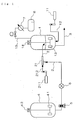
- gas-liquid mixer 21 of which an enlarged apparent view is shown in Fig. 2 can be arranged in tube 2 for transferring polymer solution.
- steam is fed from steam feed tube 212 for gas-liquid mixer into the polymer solution inside the gas-liquid mixer 21, to sufficiently put the polymer and steam in contact with each other, so that the polymer is modified into crumb of a diameter of several millimeters, particularly about 4 to 7 mm.
- solvent removal can be done more efficiently.
- warm water is preferably fed into the polymer solution before steam is put in contact with the polymer solution in the tube. In such manner, subsequent contact efficiently between steam and the polymer solution can be improved to enable more efficient solvent removal.
- the position where warm water should be fed any position located before the position where steam and the polymer solution are put in contact with each other is satisfactory, with no specific limitation.
- warm water can be fed from warm water source 22 through warm water feed tube 221 to the tube 2 for transferring polymer solution with feed devices such as pump (not shown in the figure).
- the feeding position is more preferably close to the position where steam and the polymer solution are put in contact with each other.
- the pressure and temperature of the steam to be fed to the tubes have no specific limitation, unless the advantages of the invention are deteriorated.
- the pressure is 0.1 to 10 MPa, particularly 0.2 to 2 MPa on a gauge pressure basis, while the temperature is preferably 110 to 420 °C, particularly 140 to 300 °C.
- the amount of the steam to be fed into the tube is 0.5-to 2-folds, particularly 0.7- to 1.5-folds, preferably 0.8- to 1.2-folds of the calculated amount thereof required for the evaporation of the solvent.
- the amount thereof is substantially the theoretical amount (0.9- to 1.1-fold the calculated amount thereof).
- the theoretical amount means the amount of steam with calories (total of whole latent heat and whole sensible heat) required for evaporating solvent.
- the theoretical amount of steam required for evaporating (vaporizing) solvent varies, depending on the solvent type, the temperature of polymer solution to be fed, and the like. Generally, the calculated amount is 0.2 to 0.4 in mass ratio to the solvent. In case of cyclohexane, for example, the calculated amount is about 0.25 to 0.32.
- the steam to be fed into the tube is preferably at 10 to 90 % by mass, although the amount of the steam varies, depending on the solvent type and the number of units of the tank for removing solvent.
- the amount of steam to be fed into the tube is preferably close to the calculated amount required for evaporating solvent.
- the ratio of the amount of steam to be fed into the tube is decreased.
- the ratio of the amount of steam to be fed into the tube is increased.
- the whole amount of steam is large as 100 parts by mass or more per 100 parts by mass of the solvent
- 10 to 50 % by mass, particularly 15 to 40 % bymass in 100 % bymass of the whole steam amount is preferably fed into the tube.
- 20 to 90 % by mass, particularly 30 to 80 % by mass in 100 % by mass of the whole steam amount is preferably fed into the tube.
- the total amount of steam to be fed into the tube or the gas-liquid mixer and the tank for removing solvent varies depending on the solvent type, the intended concentration of residual solvent, and the like.
- the total amount of steam is preferably 50 to 200 parts by mass, particularly preferably 60 to 150 parts by mass in case of a single one unit of the tank for removing solvent.
- the total amount of steam is less than 50 parts by mass, sufficient solvent removal is unlikely to occur.
- the whole amount of steam can be reduced, so that the total amount of steam can be reduced to 30 to 100 parts by mass, particularly 30 to 70 parts by mass.
- the total amount of steam is less than 30 parts by mass, sufficient solvent removal is unlikely to occur.
- the amount of warm water to be fed is not specifically limited by the kinds of the polymer, the solvent and the like.
- the amount thereof canbe 0.1-to 2-fold, preferably 0.2- to one-fold in mass ratio that of the polymer solution.
- the temperature of the warm water is satisfactorily the temperature of the polymer solution or higher, with no specific limitation. Generally, the temperature is 60 to 110 °C, preferably 70 to 100 °C.
- the method for removing solvent from polymer solution in accordance with the invention can be practiced with an apparatus for removing solvent, which is equipped with at least one member of a partition member, a sprinkler, and a specific flush nozzle structure as described below. Further, a member for suppressing crumb dispersion can be mounted on the specific flush nozzle structure. Additionally, at least one of a partition member, a sprinkler, and a specific flush nozzle structure, and a member for suppressing crumb dispersion can individually be used in combination with the warm water feed.
- the method for removing solvent only single unit of the tank for removing solvent is suffice for efficient solvent removal.
- additional tanks for removing solvent may be arranged in communication with the tank for removing solvent where a polymer solutionis charged, for multi-step solvent removal.
- solvent can be removed efficiently as a whole by adjusting the pressure of a tank charged with a solvent-containing polymer having a smaller solvent content on the side of a latter step to a pressure higher than the pressure of a tank in a former step.
- the apparatus for removing solvent in accordance with the invention includes a tank for removing solvent, a tube for transferring polymer solution to transfer the polymer solution to the tank for removing solvent, having one end opened in the tank for removing solvent, a steam feed tube for piping in communication with the tube for transferring polymer solution having to feed steam to the tube, and a steam feed tube for tank having one end opened in the tank for removing solvent.
- a gas-liquid mixer may be arranged in the tube for transferring polymer solution.
- steam feed into the tube for transferring polymer solution is fed or steam is fed from a steam feed tube in communication with the gas-liquid mixer.
- any gas-liquid mixer is satisfactory with no specific limitation, as long as the mixer has a function to mix steam with polymer solution. However, such gas-liquid mixer at higher mix efficiency is preferable.
- the individual steam feed tubes described above are separately connected to a steam source.
- Steam feed devices such as pump for transferring steam from the steam source into the individual tubes are arranged. Steam may be transferred and fed due to the difference in pressure between the steam source and each of the units to be fed with steam.
- the polymer solution is fed from a polymerization tank or an intermediate tank for storing polymer solution and transferred in the tube for transferring polymer solution.
- the polymerization tank and the intermediate tank are individually arranged with an agitation unit such as agitation wing for agitating the inside of the individual tanks.
- agitation wing agitation wings of the related art, for example, a disk turbine wing and a slant puddle wing may be used.
- corn cave-type agitation wing 13a in Fig.13 can preferably be used.
- steam can be dispersed so well that polymer and steam can be sufficiently put in contact with each other, leading to more efficient solvent removal and the reduction of the amount of steam required for solvent removal.
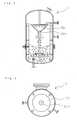
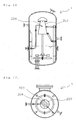
- partition member 101 can be arranged in the tank for removing solvent so as to partition the gas phase part thereof into an upper part and a lower part.
- the partition member is generally arranged downward the position where a flush nozzle arranged in communication with the tube for transferring polymer solution is opened.
- the whole of the partition member may be positioned downward the position where the flush nozzle is opened.
- a part or the whole of the flush nozzle may be overlapped with the partition member in the upper side thereof in the vertical direction from the positional standpoint.
- the partition member 101 has opening 1011 at least on the center part thereof. From the opening, crumb falls down to the liquid phase part.
- the shape of the partition member 101 should be just a shape to readily make crumb fall down toward the liquid phase part, with no specific limitation.
- the shape is preferably for example a corn shape slanting downward from the side of the inner wall of the tank 1 for removing solvent toward the side of the center thereof.
- the slanting angle is not specifically limited.
- the angle is 10 to 60 °, particularly 20 to 50 ° to the cross-sectional face of the tank 1 for removing solvent.
- the shaft of agitation wing is inserted through the opening 1011.
- the partition member 101 has an opening only on the center part but no opening on the side of the inner wall.
- the partition member has an opening only on the center part, convection current of steam and solvent in the tank can be suppressed, so that steam and solvent can efficiently be recovered from the upper part of the tank, particularly the top thereof.
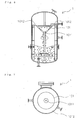
- the partition member with an opening only at the center part can be formed by arranging partition plate 1012 of a disk shape between the periphery of a partition member of a corn type and the like and the inner wall of the tank, and the like.
- the material of the partition member is with no specific limitation.
- the partition member can be formed from metals, resins and the like.
- As the metals stainless steel and aluminium can be used.
- As the resins resins with great solvent resistance and high thermal resistance with no occurrence of deformation and the like at the temperature for solvent removal can be used, which are for example fluororesin, polyamide resin, and polyester resin.
- the fluororesin includes for example polytetrafluoroethylene and fluorinated ethylene polypropylene copolymer.
- the polyamide resin includes for example polyamide 6 and polyamide 66.
- the polyester resin includes for example polyethylene terephthalate and polyethylene naphthalate. Among these resins, fluororesin with good solvent resistance, thermal resistance and release properties is particularly preferable.
- Partition members of metals, resins and the like may be used as they are. So as to suppress crumb adhesion, however, these partition members preferably have a property of suppressing polymer adhesion.
- the property of suppressing polymer adhesion can be given by forming a layer of a resin with excellent release properties such as fluororesin, at least on the upper face of a partition member made of metals and the like. Further, a partition member with a property of suppressing polymer adhesion can be prepared by forming the partition member, using a material with excellent release properties such as fluororesin.
- a sprinkler may be arranged inside the tank to sprinkle warm water so as to suppress crumb adhesion or so as to make deposited crumb fall down to the liquid phase part.
- the sprinkler is generally arranged upper than the position where the flush nozzle is opened in the gas phase part of the tank for removing solvent, so that warm water is sprinkled below the tank for removing solvent (just underneath or obliquely downwardly toward the inner wall face of the tank or toward the inner side of the tank). Via warm water sprinkled from the sprinkler, crumb can securely fall down toward the liquid phase part and crumb deposited on the inner wall face of the tank, the upper face of the partition member and the like can fall down to the liquid phase part.
- Warm water is preferably sprinkled uniformly on the cross-sectional face of the tank for removing solvent.
- the sprinkler preferably has such a structure to enable such sprinkling.
- the temperature of warm water is with no specific limitation.
- the temperature is preferably not less than a temperature inside the tank for removing solvent [Tt (°C)], particularly Tt to (Tt + 5) °C, more preferably Tt to (Tt + 10) °C.
- the sprinkler is arranged so as to protrude from the side of the warm water inlet into the tank, and has opened slits (continuous slits over the whole length of the sprinkler or plural slits of a specific length), holes (any shape of circle, oblong or polygon or the like, with no specific limitation to the shape) and the downwardly to the tank for removing solvent.
- the plane shape thereof is with no specific limitation.
- the sprinkler is capable of uniformly sprinkling warm water over the whole periphery of the inner wall face of the tank.
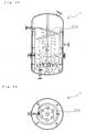
- Figs. 8 and 9 show an example of ring sprinkler 102 protruding from the side of the warm water inlet in the tank equipped with a sprinkling port.
- the sprinkler may be in a character C shape (both the ends are closed) protruding from the side of the warm water inlet in the tank, where the sprinkler partially wanes on the side opposite to the side of the warm water inlet.
- the structure of the sprinkling port is with no specific limitation.
- the port is preferably a slit arranged to sprinkle warm water beneath the sprinkler (just underneath or obliquely downwardly toward the inner wall face of the tank or toward the inner side of the tank).
- the sprinkling port 102 may be plural holes arranged at an appropriate interval along the peripheral direction. Further, the sprinkler 102 is particularly useful when arranged in combination with partition member 101 equipped with partition plate 1012 as shown in Figs. 12 and 13. As such arrangement in combination, crumb adhesion on the upper face of the partition member 101 can sufficiently be suppressed.
- the fall of crumb down to the liquid phase part can be promoted with a specific flush nozzle structure to reduce the flush speed of the polymer solution discharged from the flush nozzle arranged in communication with the tube for transferring polymer solution. Further, the flow of the solvent vapor down to the side of the liquid phase can be suppressed with the specific flush nozzle structure.
- the flush nozzle structure includes for example a flush nozzle with a branch tube on the side of the tip end.
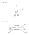
- the branch tube includes for example inverted Y character tube 201 on the tip end of a flush nozzle as shown in Fig.14, and inverted T character tube 202 on the tip end of a flush nozzle as shown in Fig.15.
- the tube has (1) a structure with slit 2021, holes or the like opened toward the downward portion of the tank for removing solvent on both the sides of a cross tube (the left and right are closed) or (2) a structure (tournament structure) with vertical tubes arranged downwardly in contiguous with the left and right ends of the cross tube.
- flush nozzle structure is a structure with at least cylinder 203 opened toward the downward portion of the tank for removing solvent, and flush nozzle 204 arranged in communication with the tube for transferring polymer solution and opened along the direction of the diameter of the cylinder in the vicinity 2031 of the innerwall face of the cylinder body, as shown in Figs. 16 and 17.
- flushed crumb descends on the inner wall face of the cylinder while the crumb draws a spiral curve, to suppress the flush speed and more securely make crumb fall down to the liquid phase part.
- the flush nozzle may be arranged in contact with the inner wall face of the cylinder or the flush nozzle may be opened at a position apart from the inner wall face within a range such that crumb can descend on the inner wall face of the cylinder while the crumb draws a spiral curve.
- flush nozzle structure is a structure such that an opening is arranged toward the downward portion of the tank for removing solvent on spiral tube 205 formed in a spiral shape along the vertical direction of the tank 1 for removing solvent, as shown in Figs. 18 and 19.
- the opening may also be a slit or plural holes arranged at an appropriate interval along the peripheral direction.
- a still another example of the flush nozzle structure is baffle 2061 arranged in the inside of large-diameter tube 206 arranged on the tip end of the flush nozzle, as shown in Figs. 20 and 21.
- the flush speed is suppressed and crumb dispersion is also suppressed owing to the collision of the polymer solution against the baffle and the tip end of the large-diameter tube.
- the baffle is arranged in the inside of the large-diameter tube, additionally, crumb dispersion is suppressed more effectively with the large-diameter tube.
- the large-diameter tube may be of a constant diameter over the whole length or may be of an enlarging diameter toward the lower part thereof. In case of the enlarging diameter, crumb dispersion can be adjusted, depending on the angle of the enlargement.
- flush nozzle structure is a curved tube with a curved tube part (see Fig. 25 below) which is arranged on the tip end of the flush nozzle.
- the flush speed is suppressed by the collision of the polymer solution against the tube wall at the curved tube part and the tip end of such large diameter. The dispersion of the polymer solution flushed can be suppressed.
- the various flush nozzle structure types described above may be of a structure arranged with a member for suppressing crumb dispersion.
- the member for suppressing crumb dispersion is arranged so as to sandwich or enclose the flush nozzle structure and is opened toward the downward portion of the tank for removing solvent. In such manner, crumb dispersion can be suppressed more, and crumb adhesion onto the inner wall face of the tank can sufficiently be suppressed.
- the flush nozzle structure is a branch tube
- a skirt member arranged in a way to enclose the branch tube part and opened along the downward portion is listed as the member for suppressing crumb dispersion.
- the distance between the wall surfaces opposite to each other in the skirt member maybe constant.
- a skirt member enlarging at an appropriate angle toward the downward portion of the tank for removing solvent is more preferable.
- the angle of the enlargement is with no specific limitation. However, taking account of the distance from the flush nozzle to the liquid phase part, the diameter of the tank for removing solvent and the like, the angle may more preferably be an angle at which dispersed crumb can fall down to the liquid phase part with no adhesion of dispersed crumb on the inner wall face of the tank.
- Still another example of the member for suppressing crumb dispersion is at least a pair of plates arranged in an opposite manner to each other to sandwich the branch part from both the sides thereof and opened downwardly.
- the interval of a pair of individual plates may be equal throughout.
- the interval may preferably be enlarged at an appropriate angle toward the downwardness of the tank for removing solvent.
- the angle of the enlargement is with no specific limitation. Taking account of the distance from the flush nozzle to the liquid phase part, the diameter of the tank for removing solvent and the like, the angle may more preferably be an angle at which dispersed crumb can fall down to the liquid phase part with no adhesion of dispersed crumb on the inner wall face of the tank.
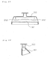
- a specific example of such member for suppressing crumb dispersion as arranged on the flush nozzle structure in combination is inverted T character tube 202 arranged on the side of the tip end of the flush nozzle, on which skirt member 301 is arranged in a manner to be opened toward the downwardness of the tank for removing solvent, as shown in Figs.22 and 23. Owing to the skirt member to suppress crumb dispersion and the adjustment of the enlarging angle, almost the whole amount of dispersed crumb can fall down to the liquid phase part with no adhesion thereof on the inner wall face of the tank.
- Such member for suppressing crumb dispersion is large-diameter tube 302 of a larger diameter than those of individual branch tubes as arranged on the tip ends of the individual branch tubes 2022 of inverted T character tube 202 with branch tubes, as shown in Fig.24.
- the large-diameter tube may be of a constant diameter over the whole length or may have a diameter enlarging downwardly. In case of the enlarging diameter, crumb dispersion can be adjusted, depending on the enlarging angle.
- Such member for suppressing crumb dispersion is large-diameter tube 2071 arranged on the tip end of the flush nozzle structure in case that the nozzle structure is curved tube 207, as shown in Fig.25.
- the crumb dispersion is suppressed and by the adjustment of the length and opening diameter of the large-diameter tube, almost the whole amount of dispersed crumb can fall down to the liquid phase part with no adhesion thereof on the inner wall face of the tank for removing solvent.
- the large-diameter tube may be of a constant diameter over the whole length or may have a diameter enlarging downwardly.
- crumb dispersion can be adjusted, depending on the enlarging angle.
- a curved tube with two curved parts bent approximately at a right angle may not necessarily be a right angle.
- the curve may have an appropriate angle.
- the angles of the two curved tube parts may be the same or different.
- Such member for suppressing crumb dispersion is a flush nozzle formed of large-diameter flush tube 303 arranged on the tip end of the tube for transferring polymer solution, as shown in Figs. 26 and 27.
- the flush tube may be of a constant diameter over the whole length or may have a diameter enlarging downwardly. In case of the enlarging diameter, crumb dispersion can be adjusted, depending on the enlarging angle.
- the apparatus of the invention includes, for example, (1) an apparatus for removing solvent arranged with a partition member, a sprinkler or a specific flush nozzle structure without having any gas-liquid mixer; (2) an apparatus for removing solvent arranged with any combination of two of a partition member, a sprinkler and a specific flush nozzle structure, without having any gas-liquid mixer; and (3) an apparatus for removing solvent arranged with a combination of a partition member, a sprinkler and a specific flush nozzle structure, without having any gas-liquid mixer.
- the apparatus includes for example (4) an apparatus for removing solvent with a gas-liquid mixer, as arranged with a partition member, a sprinkler or a flush nozzle structure; (5) an apparatus for removing solvent with a gas-liquid mixer, as arranged with any combination of two of a partition member, a sprinkler and a flush nozzle structure; and (6) an apparatus for removing solvent for removing solvent with a gas-liquid mixer, as arranged with a partition member, a sprinkler and a flush nozzle structure.
- the specific flush nozzle structure may be any of branch tubes of the inverted Y character type and inverted T character type, cyclone-type flush nozzle, spiral-type flush nozzle, a flush nozzle arranged with a baffle inside a large-diameter tube arranged on the tip end of the flush nozzle, and a flush nozzle composed of a curved tube with a curved tube part on the tip end thereof, as described above.
- a member for suppressing crumb dispersion may be arranged on the flush nozzle structure.
- the member for suppressing crumb dispersion may be any of the skirt member and the various large-diameter tubes described above. Depending on the constitution of the flush nozzle structure, an appropriate member for suppressing crumb dispersion can be arranged.
- a unit for feeding warm water with a warm water feed device such as pump from a source for feeding warm water through a warm water feed tube to the tube for transferring polymer solution
- the unit for feeding warm water can be used in combination with all combinations of the various constitutional members described above, namely [1] gas-liquid mixer, [2] partition member, [3] sprinkler and [4] flush nozzle structure (despite the presence or absence of the member for suppressing crumb dispersion).
- the unit for feeding warm water is preferably used in combination with the gas-liquid mixer.
- the unit for feeding warm water may be used in combination with each of (1), (2), (3), (4), (5) and (6). To the position where warm water is fed, the amount of warm water to be fed, the mass ratio of warm water to polymer solution, and the temperature of warm water, the descriptions above can be applied as they are.
- Polymer tank 4 is a polymerization tank or an intermediate tank for storing polymer solution and is generally equipped with agitation wing 41 for polymer tank (motor is marked with 42). Polymer solution is supplied from polymer tank 4 with pump 5 and measured with flow meter 6, so that a given amount of polymer solution is transferred in tube 2 for transferring polymer solution.
- the quantitative pump includes for example gear pump, diaphragm pump and plunger pump.
- warm water can be fed to the tube 2 for transferring polymer solution via warm water feed tube 221 so as to put steam and polymer solution efficiently in contact with each other to further improve the efficiency of solvent removal, as shown in Fig.28.
- the polymer solution is fed to gas-liquid mixer 21 as shown in Fig.2; in the inside of the gas-liquid mixer 21, steam feed from steam source 211 for gas-liquid mixer via steam feed tube 212 for gas-liquid mixer is put sufficiently in contact with polymer solution, so that the solvent is vaporized, while the polymer is modified into crumb.
- the solution is charged in the gas phase part of the tank 1 for removing solvent, the vaporized solvent is separated from the polymer.
- the crumb falls down to and is mixed in the liquid phase part of the tank 1 for removing solvent, while the liquid phase part is agitated with agitation wing 13 for the tank for removing solvent (motor is marked with 14).
- solvent removal is done by steam stripping with steam feed from steam source 11 for the tank for removing solvent.
- the polymer after solvent removal is drawn from the tank 1 for removing solvent and is transferred in the tube 3 for transferring recovered polymer, for recovery.
- the solvent removed from the polymer solution is recovered through tube 15 for recovering solvent, is cooled with cooler 7 for liquefaction, and is then transferred into decanter 8.
- the decanter 8 the solvent is separated from solids, and is then purified and subsequently recovered.
- the steam to the liquid phase part in the tank 1 for removing solvent may be fed from the bottom part of the tank 1 for removing solvent or may be fed from a side part thereof.
- the opening of the steam feed tube 12 for the tank for removing solvent may be of a simple form such that the tube itself is opened. Otherwise, the opening may be of a structure from which steam can be fed at a higher speed.
- the structure may be for example a structure composed of numerous holes of a smaller diameter than the diameter of the tube, as arranged and opened in a ring form in particular.
- the structure may be for example a structure composed of plural capillaries of a smaller diameter than the diameter of the tube, as opened in the same direction, particularly along the peripheral direction of the tank 1 for removing solvent.
- a polymer solution (at temperature of 60 °C) containing styrene • butadiene copolymer (styrene content; 10 % by mass) at 20 % by mass, as obtained by copolymerizing styrene and butadiene together using n-butyl lithium as a polymerization initiator was treated for solvent removal with the apparatus shown in Fig.1.
- the polymer solution was charged through the tube 2 for transferring polymer solution into the gas phase part of the tank 1 for removing solvent (made of stainless steel; inner volume of 2 m 3 ) to remove the solvent.
- the polymer solution was further treated by steam stripping for removing solvent.
- the flush nozzle on the side of the tip end of the tube 2 for transferring polymer solution is of the straight tube form of the tube 2 for transferring polymer solution as it is.
- the pressure inside the tank for removing tank was 0.04 MPa on a gauge pressure basis.
- Solvent was removed in the same manner as in the Experimental Example 1, except that the total of the amount of steam to be fed to the gas-liquid mixer and the amount of stem to be fed to the tank for removing solvent was 150 parts by mass when the solvent contained in polymer solution was defined as 100 parts by mass and the individual amounts to be fed were changed as shown in Table 1.
- Solvent removal was done in the same manner as in Experimental Example 1, except for the use of a mixture solvent of 90 % by mass of cyclohexane and 10 % by mass of n-heptane as a reaction solvent and a polymer solution (at temperature of 60 °C) containing styrene • butadiene rubber (styrene content; 35 % by mass) at 15 % by mass, as obtained by copolymerizing styrene and butadiene together using n-butyl lithium as a polymerization initiator and except that the total of the amounts of steam feed to the gas-liquid mixer and to the tank for removing solvent was 70 parts by mass when the solvent contained in the polymer solution was defined as 100 parts by mass and the amounts thereof individually fed thereto were changed as shown in Table 1.
- concentration of the residual solvent in the polymer after solvent removal means the concentration of the solvent in the dried polymer and was determined by gas chromatography (apparatus with FID).
- the numerical figures in parenthesis in the columns of the amount of steam feed show the ratios (unit; % by mass) of individual amounts of steam feed to the gas-liquid mixer and to the tank for removing solvent in case that the total amount of steam is defined as 100 % by mass.
- the concentrations of the residual solvent in Examples 1 through 4 in Experimental Example 1 were 1.7 to 2.4 % by mass and were superior to Comparative Example 1 at 2.9 % by mass and Comparative Example 2 at 3.7 % by mass.
- the concentrations of the residual solvent in Examples 5 and 6 in Experimental Example 2 were 1.2 to 1.4 % by mass and were superior to Comparative Example 3 at 1.6 % by mass and Comparative Example 4 at 1.5 % by mass.
- the concentrations of the residual solvent in Examples 7 through 9 in Experimental Example 3 were 1.7 to 3.0 % by mass and were superior to Comparative Example 5 at 3.2 % bymass and Comparative Example 6 at 3.9 % by mass. It is shown that in case that steam was fed at an amount as large as 150 parts by weight as the whole amount of steam to solvent as in Experimental Example 2, in particular, the concentrations of the residual solvent were lower.
- Fig.29 representing the concentration of residual solvent in case of changing the steam amount to the gas-liquid mixer /whole amount of steam (Sf/St) in Experimental Example 2, the concentration of residual solvent is the lowest when Sf/St is 0.3.
- the steam at 0.3, namely of 30 parts by mass is a feed amount approximate to the calculated amount required for solvent evaporation. It is shown that the concentration of residual solvent is larger when Sf/St is a value smaller or larger than the value.
- a corn-type partition member see Figs. 4 and 5 slanting downward (slanting angle; 45 °) from the side of the inner wall of a tank for removing solvent toward the side of the center thereof, as arranged so that the gas phase part of the tank for removing solvent might be partitioned into upper and lower parts, where a flush nozzle was mounted on the upper part of the partition member, a polymer solution was flushed for solvent removal.
- Example 14 Using an apparatus equipped with a partition member arranged with a disk partition plate as used in Example 14 and a flush nozzle mounted on the upper part of the partition member, where a sprinkler was arranged on the upper part of the flush nozzle (see Figs. 12 and 13) , warm water at the same temperature as that of the tank for removing solvent was sprinkled at a flow of 400 liters/hour for solvent removal.
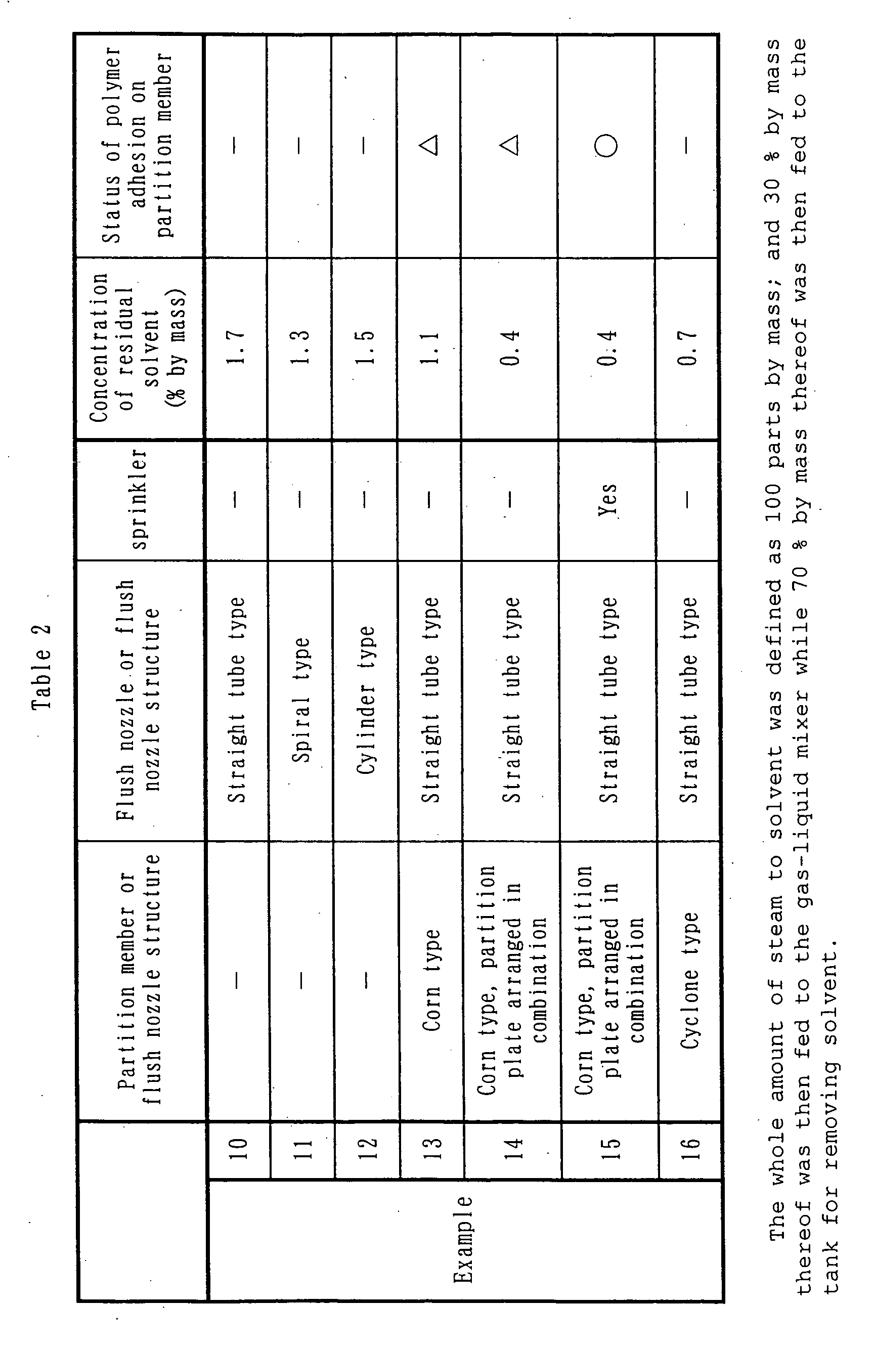
- Example 10 through 16 are shown in Table 2. Additionally, the status of polymer adhesion on the upper face of the partition member was observed visually. The results are also shown in Table 2. The status of polymer adhesion was assessed on the basis of the following two grades.
- Example 13 where the corn-type partition member was arranged, the more excellent result that the concentration of residual solvent was as low as 1.1 % by mass was obtained.
- Example 14 and 15 where the partition member was arranged and the partition plate was also arranged in combination, further, the especially excellent result that the concentrations of residual solvent were or extremely low, as 0.4 % by mass was obtained.
- Example 16 using an apparatus equipped with a cyclone type flush nozzle structure, the excellent result that the concentration of residual solvent was extremely reduced to 0.7 % by mass was obtained.
- Example 15 As to the status of polymer adhesion, alternatively, polymer adhesion was reduced in Example 15 where a partition member and a sprinkler were arranged in combination, which was excellent. In Examples 14 and 15, the concentrations of residual solvent were equal. As to the status of polymer adhesion, however, Example 15 is superior in which the corn-type partition member arranged with a partition plate is additionally equipped with a sprinkler, demonstrating and supporting the effect of such sprinkler.
Landscapes
- Chemical & Material Sciences (AREA)
- Chemical Kinetics & Catalysis (AREA)
- Health & Medical Sciences (AREA)
- Medicinal Chemistry (AREA)
- Polymers & Plastics (AREA)
- Organic Chemistry (AREA)
- General Chemical & Material Sciences (AREA)
- Addition Polymer Or Copolymer, Post-Treatments, Or Chemical Modifications (AREA)
- Vaporization, Distillation, Condensation, Sublimation, And Cold Traps (AREA)
- Processes Of Treating Macromolecular Substances (AREA)
Abstract
Description

Claims (32)
- A method for removing solvent from polymer solution by putting the polymer solution in contact with steam to remove the solvent by steam stripping, comprising:a step of feeding a part of said steam into a tube for transferring said polymer solution to a tank for removing solvent; anda step of feeding the remaining part of said steam into the inside of said tank for removing solvent.
- A method for removing solvent from polymer solution according to Claim 1, wherein a gas-liquid mixer is arranged in said tube and a part of said steam is fed into said gas-liquid mixer.
- A method for removing solvent from polymer solution according to Claim 1, wherein the amount of the steam to be fed into said tube is at 10 to 90 % by mass when the whole amount of said steam is defined as 100 % by mass.
- A method for removing solvent from polymer solution according to Claim 1, wherein the polymer contained in said polymer solution is butadiene rubber, isoprene rubber, styrene / butadiene rubber, styrene / isoprene rubber, ethylene / α-olefin copolymer rubber, ethylene / α-olefin / non-conjugated diene copolymer rubber, butyl rubber, styrene / butadiene / styrene block copolymer, hydrogenated styrene / butadiene / styrene block copolymer, butadiene resin or acrylic resin.
- A method for removing solvent from polymer solution according to Claim 1, wherein said solvent is at least one selected from the group consisting of cyclohexane, cyclopentane, cycloheptane, toluene, benzene, xylene, n-hexane, n-pentane, isopentane, n-heptane, n-octane, n-decane, and dichloromethane.
- A method for removing solvent from polymer solution according to Claim 1, wherein the boiling point of said solvent at a pressure of 0.1 MPa is 25 to 180 °C.
- A method for removing solvent from polymer solution according to Claim 1, wherein said polymer solution is continuously fed into said tank for removing solvent and the polymer contained in said polymer solution is continuously recovered.
- A method for removing solvent from polymer solution according to Claim 1, wherein the amount of the steam to be fed into said tube is 0.5- to 2-folds of the theoretical amount thereof required for the evaporation of said solvent.
- A method for removing solvent from polymer solution according to Claim 1, wherein said tank for removing solvent is equipped with at least one selected from the following members (1), (2) and (3):(1) a partition member arranged beneath the position where a flush nozzle arranged in communication with said tube for transferring polymer solution is opened, so that the gas phase part of said tank for removing solvent may be partitioned into an upper part and a lower part, to suppress the flow of the solvent vapor discharged from said flush nozzle down to the side of the liquid phase;(2) a sprinkler arranged inside said tank for removing solvent to sprinkle warm water so as to suppress polymer adhesion or make deposited polymer flow down to the liquid phase part;(3) a flush nozzle structure to reduce the flush speed of the polymer solution discharged from a flush nozzle arranged in communication with said tube for transferring polymer solution and to suppress the flow of the solvent vapor down to the side of the liquid phase.
- A method for removing solvent from polymer solution according to Claim 2, wherein said tank for removing solvent is equipped with at least one selected from the following members (1), (2) and (3):(1) a partition member arranged beneath the position where a flush nozzle arranged in communication with said tube for transferring polymer solution is opened, so that the gas phase part of said tank for removing solvent may be partitioned into an upper part and a lower part, to suppress the flow of the solvent vapor discharged from said flush nozzle down to the side of the liquid phase;(2) a sprinkler arranged inside said tank for removing solvent to sprinkle warm water so as to suppress polymer adhesion or make deposited polymer flow down to the liquid phase part;(3) a flush nozzle structure to reduce the flush speed of the polymer solution discharged from a flush nozzle arranged in communication with saidtube for transferringpolymer solution and to suppress the flow of the solvent vapor down to the side of the liquid phase.
- An apparatus for removing solvent, including a tank for removing solvent, comprising:a tube for transferring polymer solution to transfer polymer solution to the tank for removing solvent, one end of which is opened in the tank for removing solvent,a steam feed tube for piping which is in communication with said tube for transferring polymer solution to feed steam to the said tube, and a steam feed tube for tank, one end of which is opened in said tank for removing solvent.
- An apparatus for removing solvent according to Claim 11, wherein said apparatus is equipped with a gas-liquid mixer arranged in said tube for transferring polymer solution, and a steam feed tube for the gas-liquid mixer which is in communication with said tube for transferring polymer solution or said gas-liquid mixer to feed steam into said gas-liquidmixer.
- An apparatus for removing solvent according to Claim 11, wherein said apparatus is equipped with a partition member arranged beneath the position where a flush nozzle arranged in communication with said tube for transferring polymer solution is opened, so that the gas phase part of said tank for removing solvent may be partitioned into an upper part and a lower part, to suppress the flow of the solvent vapor discharged from said flush nozzle down to the side of the liquid phase.
- An apparatus for removing solvent according to Claim 13, wherein said partition member has a corn-type shape slanting downward from the side of the inner wall of said tank for removing solvent toward the side of the center thereof and has an opening only on the center part thereof.
- An apparatus for removing solvent according to Claim 12, wherein said apparatus is equipped with a partition member arranged beneath the position where a flush nozzle arranged in communication with said tube for transferring polymer solution is opened, so that the gas phase part of said tank for removing solvent may be partitioned into an upper part and a lower part, to suppress the flow of the solvent vapor discharged from said flush nozzle down to the side of the liquid phase.
- An apparatus for removing solvent according to Claim 15, wherein said partition member has a corn-type shape slanting downward from the side of the inner wall of said tank for removing solvent toward the side of the center thereof and has an opening only on the center part thereof.
- An apparatus for removing solvent according to Claim 11, wherein said apparatus is equipped with a sprinkler arranged inside said tank for removing solvent to sprinkle warm water so as to suppress crumb adhesion or make deposited crumb flow down to the liquid phase part.
- An apparatus for removing solvent according to Claim 12, wherein said apparatus is equipped with a sprinkler arranged inside said tank for removing solvent to sprinkle warm water so as to suppress crumb adhesion or make deposited polymer flow down to the liquid phase part.
- An apparatus for removing solvent according to Claim 11, wherein said apparatus is equipped with a flush nozzle structure to reduce the flush speed of the polymer solution discharged from a flush nozzle arranged in communication with said tube for transferring polymer solution and to suppress the flow of the solvent vapor down to the side of the liquid phase.
- An apparatus for removing solvent according to Claim 19, wherein said flush nozzle structure is a flush nozzle with a branch tube arranged on the side of the tip end thereof.
- An apparatus for removing solvent according to Claim 20, wherein said apparatus being equipped with a member for suppressing crumb dispersion, and the member is arranged on the tip end of the flush nozzle and is opened toward the downwardness of said tank for removing solvent.
- An apparatus for removing solvent according to Claim 19, wherein said flush nozzle structure is equipped at least with a cylinder opened toward the downward portion of said tank for removing solvent and a flush nozzle arranged in communication with said tube for transferring polymer solution, and opened toward the diameter direction of said cylinder in the vicinity of the inner wall face of said cylinder.
- An apparatus for removing solvent according to Claim 19, wherein said flush nozzle structure is a spiral tube arranged in communication with said tube for transferring polymer solution and formed in a spiral shape along the vertical direction of said tank for removing solvent, where an opening is arranged toward the downwardness of said tank for removing solvent.
- An apparatus for removing solvent according to Claim 12, wherein said apparatus is equipped with a flush nozzle structure to reduce the flush speed of the polymer solution discharged from a flush nozzle arranged in communication with said tube for transferring polymer solution and to suppress the flow of the solvent vapor down to the side of the liquid phase.
- An apparatus for removing solvent according to Claim 24, wherein said flush nozzle structure is a flush nozzle with a branch tube arranged on the side of the tip end thereof.
- An apparatus for removing solvent according to Claim 25, wherein said apparatus is equipped with a member for suppressing crumb dispersion, where the member is arranged on the tip end of said flush nozzle and is opened toward the downward portion of said tank for removing solvent.
- An apparatus for removing solvent according to Claim 24, wherein said flush nozzle structure is equipped at least with a cylinder opened toward the downward portion of said tank for removing solvent and a flush nozzle arranged in communication with said tube for transferring polymer solution and opened toward the diameter direction of said cylinder in the vicinity of the inner wall face of said cylinder.
- An apparatus for removing solvent according to Claim 24, wherein said flush nozzle structure is a spiral tube arranged in communication with said tube for trans ferring polymer solution and formed in a spiral shape along the vertical direction of said tank for removing solvent, where an opening is arranged toward the downwardness of said tank for removing solvent.
- An apparatus for removing solvent from polymer solution according to Claim 11, wherein said apparatus is equipped with:a partition member arranged beneath the position where a flush nozzle arranged in communication with said tube for transferring polymer solution is opened so that the gas phase part of said tank for removing solvent may be partitioned into an upper part and a lower part, to suppress the convection current of the solvent vapor discharged from said flush nozzle toward the side of the liquid phase; anda sprinkler arranged inside said tank for removing solvent to sprinkle warm water so as to suppress polymer adhesion or make deposited polymer flow down to the liquid phase part.
- An apparatus for removing solvent according to Claim 12, wherein said apparatus is equipped with:a partition member arranged beneath the position where a flush nozzle arranged in communication with said tube for transferring polymer solution is opened so that the gas phase part of said tank for removing solvent may be partitioned into an upper part and a lower part, to suppress the convection current of the solvent vapor discharged from said flush nozzle toward the side of the liquid phase; anda sprinkler arranged inside said tank for removing solvent to sprinkle warm water so as to suppress polymer adhesion or make deposited polymer flow down to the liquid phase part.
- An apparatus for removing solvent according to Claim 11, wherein said apparatus is equipped with:a sprinkler arranged inside said tank for removing solvent to sprinkle warm water so as to suppress polymer adhesion or make deposited polymer flow down to the liquid phase part; anda flush nozzle structure to reduce the flush speed of the polymer solution discharged from a flush nozzle arranged in communication with said tube for transferring polymer solution and to suppress the flow of the solvent vapor down to the side of the liquid phase.
- An apparatus for removing solvent according to Claim 12, wherein said apparatus is quipped with:a sprinkler arranged inside said tank for removing solvent to sprinkle warm water so as to suppress polymer adhesion or make deposited polymer flow down to the liquid phase part; anda flush nozzle structure to reduce the flush speed of the polymer solution discharged from a flush nozzle arranged in communication with said tube for transferring polymer solution and to suppress the flow of the solvent vapor down to the side of the liquid phase.
Applications Claiming Priority (3)
| Application Number | Priority Date | Filing Date | Title |
|---|---|---|---|
| JP2002194913 | 2002-07-03 | ||
| JP2002194913 | 2002-07-03 | ||
| PCT/JP2003/008414 WO2004007567A1 (en) | 2002-07-03 | 2003-07-02 | Method of removing solvent from polymer solution and solvent removing apparatus |
Publications (4)
| Publication Number | Publication Date |
|---|---|
| EP1533323A1 true EP1533323A1 (en) | 2005-05-25 |
| EP1533323A4 EP1533323A4 (en) | 2008-03-19 |
| EP1533323B1 EP1533323B1 (en) | 2014-03-12 |
| EP1533323B2 EP1533323B2 (en) | 2021-09-08 |
Family
ID=30112318
Family Applications (1)
| Application Number | Title | Priority Date | Filing Date |
|---|---|---|---|
| EP03741152.7A Expired - Lifetime EP1533323B2 (en) | 2002-07-03 | 2003-07-02 | Method of removing solvent from polymer solution and solvent removing apparatus |
Country Status (9)
| Country | Link |
|---|---|
| US (1) | US20050267288A1 (en) |
| EP (1) | EP1533323B2 (en) |
| JP (1) | JP3817564B2 (en) |
| KR (1) | KR20050042131A (en) |
| CN (1) | CN1315879C (en) |
| AU (1) | AU2003281036A1 (en) |
| CA (1) | CA2490770A1 (en) |
| RU (1) | RU2005102607A (en) |
| WO (1) | WO2004007567A1 (en) |
Cited By (4)
| Publication number | Priority date | Publication date | Assignee | Title |
|---|---|---|---|---|
| WO2009156755A1 (en) * | 2008-06-23 | 2009-12-30 | Operational Group Limited | Solvent recovery from waste ink by stripping with air |
| EP1815959A4 (en) * | 2004-11-19 | 2012-09-05 | Jsr Corp | PROCESS FOR DRYING A WET POLYMER |
| EP2787011A4 (en) * | 2011-11-28 | 2014-10-08 | Asahi Kasei Chemicals Corp | STEAM STRIPPING DEVICE AND STEAM STRIPPING FINISHING METHOD USING THE SAME |
| EP3778720A4 (en) * | 2018-03-28 | 2021-12-08 | Zeon Corporation | Production method for crumbs and production method for bale |
Families Citing this family (24)
| Publication number | Priority date | Publication date | Assignee | Title |
|---|---|---|---|---|
| JP2009221260A (en) * | 2008-03-13 | 2009-10-01 | Kaneka Corp | Method for producing exactly spherical particle |
| RU2542986C2 (en) | 2008-09-19 | 2015-02-27 | Ланксесс Интернасьональ Са | Method of obtaining polymers, which do not contain water and solvents |
| IT1391942B1 (en) * | 2008-11-14 | 2012-02-02 | Polimeri Europa Spa | PROCEDURE FOR OBTAINING AN ELASTOMER IN THE SOLID STAGE STARTING FROM ITS POLYMERIC SOLUTION |
| EP2368918A1 (en) * | 2010-03-24 | 2011-09-28 | LANXESS Deutschland GmbH | Process for the production of water and solvent-free polymers |
| JP5906684B2 (en) * | 2011-11-17 | 2016-04-20 | Jsr株式会社 | Synthetic rubber solution transfer method and synthetic rubber solution transfer device |
| CN102671407B (en) * | 2012-05-18 | 2014-08-06 | 中南大学 | Method and device for removing organic solvent from cathodic electrophoretic emulsion |
| CN103483483B (en) * | 2012-06-11 | 2015-09-09 | 中国石油化工集团公司 | A kind of isoprene-isobutylene rubber stripper plant and gas stripping process |
| JP2015093979A (en) * | 2013-11-14 | 2015-05-18 | 花王株式会社 | Method for producing organopolysiloxane graft polymer |
| CN104258584B (en) * | 2014-09-30 | 2017-01-25 | 周建明 | Separating system and separating method for residual monomers in polymer viscous liquid |
| CN104961846B (en) * | 2015-07-03 | 2017-03-08 | 新疆蓝德精细石油化工股份有限公司 | Improve device and its using method of cohesion process rubber oil separating effect |
| KR102089414B1 (en) | 2016-06-16 | 2020-03-16 | 주식회사 엘지화학 | Method for recovering solvent and apparatus therefor |
| KR102166467B1 (en) * | 2016-10-05 | 2020-10-16 | 주식회사 엘지화학 | Apparatus for separatiing solvent and method thereof |
| CN106334329B (en) * | 2016-11-14 | 2018-08-31 | 宁波工程学院 | A kind of de- single experimental provision of polymer emulsion |
| RU2648754C1 (en) * | 2017-04-26 | 2018-03-28 | Федеральное государственное бюджетное образовательное учреждение высшего образования "Башкирский государственный университет" | Method of purification of the return solvent |
| RU2663295C1 (en) * | 2017-05-31 | 2018-08-03 | Федеральное государственное бюджетное образовательное учреждение высшего образования "Башкирский государственный университет" | Method of purification of the return solvent |
| KR102328793B1 (en) | 2017-10-16 | 2021-11-22 | 주식회사 엘지화학 | Method for preparing conjugated diene polymer |
| WO2019187650A1 (en) * | 2018-03-28 | 2019-10-03 | 日本ゼオン株式会社 | Crumbs, production method for same, and production method for bale |
| CN108654124B (en) * | 2018-05-31 | 2020-11-24 | 万华化学集团股份有限公司 | A kind of device and method for removing volatile organic compounds in emulsion |
| CN109806609A (en) * | 2018-08-30 | 2019-05-28 | 新疆寰球工程公司 | A solution-polymerized rubber stripping kettle device and pressure control method thereof |
| KR102677554B1 (en) | 2018-12-17 | 2024-06-24 | 주식회사 엘지화학 | Method for preparing modified conjugated diene polymer |
| CN112142877B (en) * | 2019-06-27 | 2022-09-20 | 中国石油化工股份有限公司 | Coagulation method for butadiene rubber solution |
| KR102421536B1 (en) | 2019-07-15 | 2022-07-15 | 주식회사 엘지화학 | Modified conjugated diene polymer, preparing method thereof and rubber compostion comprising the same |
| KR20250106449A (en) | 2024-01-03 | 2025-07-10 | 주식회사 엘지화학 | Preparing method for polymer |
| CN120268070B (en) * | 2025-06-09 | 2025-10-03 | 中哲(浙江)高分子新材料有限公司 | A pre-flash energy-saving method for the condensation system of SSBR production equipment |
Family Cites Families (9)
| Publication number | Priority date | Publication date | Assignee | Title |
|---|---|---|---|---|
| US3469617A (en) | 1967-03-20 | 1969-09-30 | Parkson Ind Equipment Co | Method for stripping of volatile substanes from fluids |
| CA1011089A (en) * | 1973-03-26 | 1977-05-31 | Lawrence C. Baughman | Method of stripping volatile material from an aqueous dispersion of polymeric substance |
| DE2724360C3 (en) | 1977-05-28 | 1988-03-24 | Bayer Ag, 5090 Leverkusen | Process for the preparation of thermoplastic molding compounds based on vinyl polymers |
| US5191062A (en) * | 1991-09-27 | 1993-03-02 | Union Carbide Chemicals & Plastics Technology Corporation | Steam purging of granular epdm resins |
| JP3650975B2 (en) * | 1995-07-28 | 2005-05-25 | 日本エクスラン工業株式会社 | Process for producing improved acrylonitrile polymer melt |
| JP3575228B2 (en) * | 1997-05-28 | 2004-10-13 | Jsr株式会社 | Method for obtaining rubbery polymer, and rubbery polymer |
| JPH1121311A (en) * | 1997-07-02 | 1999-01-26 | Idemitsu Petrochem Co Ltd | Method for removing volatile substances in polymers |
| JP5180416B2 (en) * | 2000-06-19 | 2013-04-10 | Jsr株式会社 | Polymer recovery method |
| MXPA02002026A (en) * | 2000-06-30 | 2002-08-20 | Asahi Chemical Ind | Method for hydrogenation of polymer. |
-
2003
- 2003-07-02 EP EP03741152.7A patent/EP1533323B2/en not_active Expired - Lifetime
- 2003-07-02 KR KR1020057000095A patent/KR20050042131A/en not_active Withdrawn
- 2003-07-02 AU AU2003281036A patent/AU2003281036A1/en not_active Abandoned
- 2003-07-02 RU RU2005102607/04A patent/RU2005102607A/en not_active Application Discontinuation
- 2003-07-02 CA CA002490770A patent/CA2490770A1/en not_active Abandoned
- 2003-07-02 US US10/517,761 patent/US20050267288A1/en not_active Abandoned
- 2003-07-02 CN CNB03815644XA patent/CN1315879C/en not_active Expired - Lifetime
- 2003-07-02 JP JP2004521144A patent/JP3817564B2/en not_active Expired - Fee Related
- 2003-07-02 WO PCT/JP2003/008414 patent/WO2004007567A1/en not_active Ceased
Cited By (5)
| Publication number | Priority date | Publication date | Assignee | Title |
|---|---|---|---|---|
| EP1815959A4 (en) * | 2004-11-19 | 2012-09-05 | Jsr Corp | PROCESS FOR DRYING A WET POLYMER |
| WO2009156755A1 (en) * | 2008-06-23 | 2009-12-30 | Operational Group Limited | Solvent recovery from waste ink by stripping with air |
| GB2461740B (en) * | 2008-06-23 | 2012-09-19 | Operational Group Ltd | Improvements in and relating to the processing of solvents and/or volatile components or the like |
| EP2787011A4 (en) * | 2011-11-28 | 2014-10-08 | Asahi Kasei Chemicals Corp | STEAM STRIPPING DEVICE AND STEAM STRIPPING FINISHING METHOD USING THE SAME |
| EP3778720A4 (en) * | 2018-03-28 | 2021-12-08 | Zeon Corporation | Production method for crumbs and production method for bale |
Also Published As
| Publication number | Publication date |
|---|---|
| US20050267288A1 (en) | 2005-12-01 |
| CN1315879C (en) | 2007-05-16 |
| JP3817564B2 (en) | 2006-09-06 |
| JPWO2004007567A1 (en) | 2005-11-10 |
| KR20050042131A (en) | 2005-05-04 |
| AU2003281036A1 (en) | 2004-02-02 |
| EP1533323B1 (en) | 2014-03-12 |
| CA2490770A1 (en) | 2004-01-22 |
| AU2003281036A8 (en) | 2004-02-02 |
| CN1665846A (en) | 2005-09-07 |
| WO2004007567A1 (en) | 2004-01-22 |
| EP1533323B2 (en) | 2021-09-08 |
| RU2005102607A (en) | 2005-08-20 |
| EP1533323A4 (en) | 2008-03-19 |
Similar Documents
| Publication | Publication Date | Title |
|---|---|---|
| EP1533323B1 (en) | Method of removing solvent from polymer solution and solvent removing apparatus | |
| US6211331B1 (en) | Polymer devolatilization apparatus | |
| CA3079922C (en) | A method of recovering olefins in a solution polymerisation process | |
| US2378138A (en) | Apparatus for carrying out chemical reactions | |
| US7541427B2 (en) | Method for desolvation of polymer solution | |
| EP0059106A2 (en) | Process for the separation treatment of polymer from polymer solution | |
| JP2021525290A (en) | Methods and systems for polymer production | |
| CN111295397B (en) | A kind of method for recovering olefin in solution polymerization process | |
| US20090008236A1 (en) | Process for Recovering Brominated Butadiene Polymers from Solution | |
| NO153995B (en) | VENTILATED CIGARETTE FILTER BAR. | |
| CA1211891A (en) | Process for the separation treatment of polymer from polymer solution | |
| KR20150027296A (en) | Process for continuous synthesis of a diene elastomer | |
| CA1138769A (en) | Process for stripping volatile material from aqueous latex | |
| US3261792A (en) | Preparation of latices | |
| KR102411721B1 (en) | Apparatus for preparing conjugated diene based polymer and method for preparing conjugated diene based polymer | |
| EP0058074B1 (en) | Liquid-liquid contacting process | |
| JP7468517B2 (en) | Method for producing purified chloroprene polymer latex | |
| CN109789342A (en) | Method for making the solvent purification of the production from elastomer blend | |
| WO1998018535A2 (en) | Method of extracting extractive component from a fluid | |
| HUP0302572A2 (en) | Method for producing highly reactive polyisobutenes | |
| CN121819649A (en) | Sol tower and application thereof | |
| IL210994A (en) | Solvent transfer process for organic polymers and a process for brominating a butadiene polymer | |
| BE709965A (en) | ||
| CS200486B2 (en) | Process for continuous polymerization and device for making this process | |
| JPS647089B2 (en) |
Legal Events
| Date | Code | Title | Description |
|---|---|---|---|
| PUAI | Public reference made under article 153(3) epc to a published international application that has entered the european phase |
Free format text: ORIGINAL CODE: 0009012 |
|
| 17P | Request for examination filed |
Effective date: 20041227 |
|
| AK | Designated contracting states |
Kind code of ref document: A1 Designated state(s): AT BE BG CH CY CZ DE DK EE ES FI FR GB GR HU IE IT LI LU MC NL PT RO SE SI SK TR |
|
| AX | Request for extension of the european patent |
Extension state: AL LT LV MK |
|
| DAX | Request for extension of the european patent (deleted) | ||
| A4 | Supplementary search report drawn up and despatched |
Effective date: 20080218 |
|
| RIC1 | Information provided on ipc code assigned before grant |
Ipc: B01D 1/14 20060101ALI20080212BHEP Ipc: C08F 6/10 20060101AFI20080212BHEP |
|
| 17Q | First examination report despatched |
Effective date: 20080702 |
|
| RAP1 | Party data changed (applicant data changed or rights of an application transferred) |
Owner name: JSR CORPORATION |
|
| REG | Reference to a national code |
Ref country code: DE Ref legal event code: R079 Ref document number: 60345849 Country of ref document: DE Free format text: PREVIOUS MAIN CLASS: C08F0006100000 Ipc: B01D0001140000 |
|
| GRAP | Despatch of communication of intention to grant a patent |
Free format text: ORIGINAL CODE: EPIDOSNIGR1 |
|
| RIC1 | Information provided on ipc code assigned before grant |
Ipc: C08F 6/12 20060101ALI20130909BHEP Ipc: C08C 2/06 20060101ALI20130909BHEP Ipc: B01D 1/14 20060101AFI20130909BHEP Ipc: C08F 6/10 20060101ALI20130909BHEP Ipc: B01D 3/38 20060101ALI20130909BHEP |
|
| INTG | Intention to grant announced |
Effective date: 20131004 |
|
| RIN1 | Information on inventor provided before grant (corrected) |
Inventor name: UCHIMURA, KAZUMI Inventor name: WADA, TAKESHI Inventor name: YAMAGUCHI, TOMOHIRO Inventor name: KUMAI, NARITSUGU |
|
| GRAS | Grant fee paid |
Free format text: ORIGINAL CODE: EPIDOSNIGR3 |
|
| GRAA | (expected) grant |
Free format text: ORIGINAL CODE: 0009210 |
|
| AK | Designated contracting states |
Kind code of ref document: B1 Designated state(s): AT BE BG CH CY CZ DE DK EE ES FI FR GB GR HU IE IT LI LU MC NL PT RO SE SI SK TR |
|
| REG | Reference to a national code |
Ref country code: GB Ref legal event code: FG4D |
|
| REG | Reference to a national code |
Ref country code: CH Ref legal event code: EP |
|
| REG | Reference to a national code |
Ref country code: AT Ref legal event code: REF Ref document number: 655847 Country of ref document: AT Kind code of ref document: T Effective date: 20140315 |
|
| REG | Reference to a national code |
Ref country code: IE Ref legal event code: FG4D |
|
| REG | Reference to a national code |
Ref country code: DE Ref legal event code: R096 Ref document number: 60345849 Country of ref document: DE Effective date: 20140424 |
|
| REG | Reference to a national code |
Ref country code: NL Ref legal event code: VDEP Effective date: 20140312 |
|
| REG | Reference to a national code |
Ref country code: AT Ref legal event code: MK05 Ref document number: 655847 Country of ref document: AT Kind code of ref document: T Effective date: 20140312 |
|
| PG25 | Lapsed in a contracting state [announced via postgrant information from national office to epo] |
Ref country code: SE Free format text: LAPSE BECAUSE OF FAILURE TO SUBMIT A TRANSLATION OF THE DESCRIPTION OR TO PAY THE FEE WITHIN THE PRESCRIBED TIME-LIMIT Effective date: 20140312 Ref country code: CY Free format text: LAPSE BECAUSE OF FAILURE TO SUBMIT A TRANSLATION OF THE DESCRIPTION OR TO PAY THE FEE WITHIN THE PRESCRIBED TIME-LIMIT Effective date: 20140312 Ref country code: FI Free format text: LAPSE BECAUSE OF FAILURE TO SUBMIT A TRANSLATION OF THE DESCRIPTION OR TO PAY THE FEE WITHIN THE PRESCRIBED TIME-LIMIT Effective date: 20140312 |
|
| PG25 | Lapsed in a contracting state [announced via postgrant information from national office to epo] |
Ref country code: RO Free format text: LAPSE BECAUSE OF FAILURE TO SUBMIT A TRANSLATION OF THE DESCRIPTION OR TO PAY THE FEE WITHIN THE PRESCRIBED TIME-LIMIT Effective date: 20140312 Ref country code: NL Free format text: LAPSE BECAUSE OF FAILURE TO SUBMIT A TRANSLATION OF THE DESCRIPTION OR TO PAY THE FEE WITHIN THE PRESCRIBED TIME-LIMIT Effective date: 20140312 Ref country code: EE Free format text: LAPSE BECAUSE OF FAILURE TO SUBMIT A TRANSLATION OF THE DESCRIPTION OR TO PAY THE FEE WITHIN THE PRESCRIBED TIME-LIMIT Effective date: 20140312 Ref country code: BG Free format text: LAPSE BECAUSE OF FAILURE TO SUBMIT A TRANSLATION OF THE DESCRIPTION OR TO PAY THE FEE WITHIN THE PRESCRIBED TIME-LIMIT Effective date: 20140612 Ref country code: BE Free format text: LAPSE BECAUSE OF FAILURE TO SUBMIT A TRANSLATION OF THE DESCRIPTION OR TO PAY THE FEE WITHIN THE PRESCRIBED TIME-LIMIT Effective date: 20140312 |
|
| PG25 | Lapsed in a contracting state [announced via postgrant information from national office to epo] |
Ref country code: ES Free format text: LAPSE BECAUSE OF FAILURE TO SUBMIT A TRANSLATION OF THE DESCRIPTION OR TO PAY THE FEE WITHIN THE PRESCRIBED TIME-LIMIT Effective date: 20140312 Ref country code: AT Free format text: LAPSE BECAUSE OF FAILURE TO SUBMIT A TRANSLATION OF THE DESCRIPTION OR TO PAY THE FEE WITHIN THE PRESCRIBED TIME-LIMIT Effective date: 20140312 Ref country code: SK Free format text: LAPSE BECAUSE OF FAILURE TO SUBMIT A TRANSLATION OF THE DESCRIPTION OR TO PAY THE FEE WITHIN THE PRESCRIBED TIME-LIMIT Effective date: 20140312 |
|
| REG | Reference to a national code |
Ref country code: DE Ref legal event code: R026 Ref document number: 60345849 Country of ref document: DE |
|
| PLBI | Opposition filed |
Free format text: ORIGINAL CODE: 0009260 |
|
| PG25 | Lapsed in a contracting state [announced via postgrant information from national office to epo] |
Ref country code: PT Free format text: LAPSE BECAUSE OF FAILURE TO SUBMIT A TRANSLATION OF THE DESCRIPTION OR TO PAY THE FEE WITHIN THE PRESCRIBED TIME-LIMIT Effective date: 20140714 |
|
| PLAX | Notice of opposition and request to file observation + time limit sent |
Free format text: ORIGINAL CODE: EPIDOSNOBS2 |
|
| 26 | Opposition filed |
Opponent name: LANXESS DEUTSCHLAND GMBH Effective date: 20141211 |
|
| PG25 | Lapsed in a contracting state [announced via postgrant information from national office to epo] |
Ref country code: DK Free format text: LAPSE BECAUSE OF FAILURE TO SUBMIT A TRANSLATION OF THE DESCRIPTION OR TO PAY THE FEE WITHIN THE PRESCRIBED TIME-LIMIT Effective date: 20140312 |
|
| REG | Reference to a national code |
Ref country code: DE Ref legal event code: R026 Ref document number: 60345849 Country of ref document: DE Effective date: 20141211 |
|
| PG25 | Lapsed in a contracting state [announced via postgrant information from national office to epo] |
Ref country code: LU Free format text: LAPSE BECAUSE OF FAILURE TO SUBMIT A TRANSLATION OF THE DESCRIPTION OR TO PAY THE FEE WITHIN THE PRESCRIBED TIME-LIMIT Effective date: 20140702 |
|
| REG | Reference to a national code |
Ref country code: CH Ref legal event code: PL |
|
| REG | Reference to a national code |
Ref country code: IE Ref legal event code: MM4A |
|
| PG25 | Lapsed in a contracting state [announced via postgrant information from national office to epo] |
Ref country code: CH Free format text: LAPSE BECAUSE OF NON-PAYMENT OF DUE FEES Effective date: 20140731 Ref country code: LI Free format text: LAPSE BECAUSE OF NON-PAYMENT OF DUE FEES Effective date: 20140731 |
|
| PLAF | Information modified related to communication of a notice of opposition and request to file observations + time limit |
Free format text: ORIGINAL CODE: EPIDOSCOBS2 |
|
| REG | Reference to a national code |
Ref country code: HU Ref legal event code: AG4A Ref document number: E022724 Country of ref document: HU |
|
| PLBB | Reply of patent proprietor to notice(s) of opposition received |
Free format text: ORIGINAL CODE: EPIDOSNOBS3 |
|
| PG25 | Lapsed in a contracting state [announced via postgrant information from national office to epo] |
Ref country code: SI Free format text: LAPSE BECAUSE OF FAILURE TO SUBMIT A TRANSLATION OF THE DESCRIPTION OR TO PAY THE FEE WITHIN THE PRESCRIBED TIME-LIMIT Effective date: 20140312 |
|
| PG25 | Lapsed in a contracting state [announced via postgrant information from national office to epo] |
Ref country code: IE Free format text: LAPSE BECAUSE OF NON-PAYMENT OF DUE FEES Effective date: 20140702 |
|
| PG25 | Lapsed in a contracting state [announced via postgrant information from national office to epo] |
Ref country code: MC Free format text: LAPSE BECAUSE OF FAILURE TO SUBMIT A TRANSLATION OF THE DESCRIPTION OR TO PAY THE FEE WITHIN THE PRESCRIBED TIME-LIMIT Effective date: 20140312 |
|
| PG25 | Lapsed in a contracting state [announced via postgrant information from national office to epo] |
Ref country code: GR Free format text: LAPSE BECAUSE OF FAILURE TO SUBMIT A TRANSLATION OF THE DESCRIPTION OR TO PAY THE FEE WITHIN THE PRESCRIBED TIME-LIMIT Effective date: 20140613 |
|
| PLCK | Communication despatched that opposition was rejected |
Free format text: ORIGINAL CODE: EPIDOSNREJ1 |
|
| REG | Reference to a national code |
Ref country code: FR Ref legal event code: PLFP Year of fee payment: 14 |
|
| PG25 | Lapsed in a contracting state [announced via postgrant information from national office to epo] |
Ref country code: TR Free format text: LAPSE BECAUSE OF FAILURE TO SUBMIT A TRANSLATION OF THE DESCRIPTION OR TO PAY THE FEE WITHIN THE PRESCRIBED TIME-LIMIT Effective date: 20140312 |
|
| APBM | Appeal reference recorded |
Free format text: ORIGINAL CODE: EPIDOSNREFNO |
|
| APBP | Date of receipt of notice of appeal recorded |
Free format text: ORIGINAL CODE: EPIDOSNNOA2O |
|
| APAH | Appeal reference modified |
Free format text: ORIGINAL CODE: EPIDOSCREFNO |
|
| APBQ | Date of receipt of statement of grounds of appeal recorded |
Free format text: ORIGINAL CODE: EPIDOSNNOA3O |
|
| REG | Reference to a national code |
Ref country code: FR Ref legal event code: PLFP Year of fee payment: 15 |
|
| REG | Reference to a national code |
Ref country code: FR Ref legal event code: PLFP Year of fee payment: 16 |
|
| PLAB | Opposition data, opponent's data or that of the opponent's representative modified |
Free format text: ORIGINAL CODE: 0009299OPPO |
|
| R26 | Opposition filed (corrected) |
Opponent name: LANXESS DEUTSCHLAND GMBH Effective date: 20141211 |
|
| APBU | Appeal procedure closed |
Free format text: ORIGINAL CODE: EPIDOSNNOA9O |
|
| PLAY | Examination report in opposition despatched + time limit |
Free format text: ORIGINAL CODE: EPIDOSNORE2 |
|
| PLBC | Reply to examination report in opposition received |
Free format text: ORIGINAL CODE: EPIDOSNORE3 |
|
| PLAY | Examination report in opposition despatched + time limit |
Free format text: ORIGINAL CODE: EPIDOSNORE2 |
|
| PUAH | Patent maintained in amended form |
Free format text: ORIGINAL CODE: 0009272 |
|
| STAA | Information on the status of an ep patent application or granted ep patent |
Free format text: STATUS: PATENT MAINTAINED AS AMENDED |
|
| 27A | Patent maintained in amended form |
Effective date: 20210908 |
|
| AK | Designated contracting states |
Kind code of ref document: B2 Designated state(s): AT BE BG CH CY CZ DE DK EE ES FI FR GB GR HU IE IT LI LU MC NL PT RO SE SI SK TR |
|
| REG | Reference to a national code |
Ref country code: DE Ref legal event code: R102 Ref document number: 60345849 Country of ref document: DE |
|
| PGFP | Annual fee paid to national office [announced via postgrant information from national office to epo] |
Ref country code: IT Payment date: 20220726 Year of fee payment: 20 Ref country code: GB Payment date: 20220720 Year of fee payment: 20 Ref country code: DE Payment date: 20220620 Year of fee payment: 20 Ref country code: CZ Payment date: 20220701 Year of fee payment: 20 |
|
| PGFP | Annual fee paid to national office [announced via postgrant information from national office to epo] |
Ref country code: HU Payment date: 20220720 Year of fee payment: 20 Ref country code: FR Payment date: 20220720 Year of fee payment: 20 |
|
| REG | Reference to a national code |
Ref country code: HU Ref legal event code: GB9C Owner name: ENEOS MATERIALS CORPORATION, JP Free format text: FORMER OWNER(S): JSR CORPORATION, JP |
|
| REG | Reference to a national code |
Ref country code: GB Ref legal event code: 732E Free format text: REGISTERED BETWEEN 20230209 AND 20230215 |
|
| REG | Reference to a national code |
Ref country code: DE Ref legal event code: R081 Ref document number: 60345849 Country of ref document: DE Owner name: ENEOS MATERIALS CORPORATION, JP Free format text: FORMER OWNER: JSR CORP., TOKIO/TOKYO, JP |
|
| REG | Reference to a national code |
Ref country code: DE Ref legal event code: R071 Ref document number: 60345849 Country of ref document: DE |
|
| REG | Reference to a national code |
Ref country code: GB Ref legal event code: PE20 Expiry date: 20230701 |
|
| PG25 | Lapsed in a contracting state [announced via postgrant information from national office to epo] |
Ref country code: CZ Free format text: LAPSE BECAUSE OF EXPIRATION OF PROTECTION Effective date: 20230702 |
|
| PG25 | Lapsed in a contracting state [announced via postgrant information from national office to epo] |
Ref country code: GB Free format text: LAPSE BECAUSE OF EXPIRATION OF PROTECTION Effective date: 20230701 |