EP1533266B1 - Door restrictor - Google Patents
Door restrictor Download PDFInfo
- Publication number
- EP1533266B1 EP1533266B1 EP04025859.2A EP04025859A EP1533266B1 EP 1533266 B1 EP1533266 B1 EP 1533266B1 EP 04025859 A EP04025859 A EP 04025859A EP 1533266 B1 EP1533266 B1 EP 1533266B1
- Authority
- EP
- European Patent Office
- Prior art keywords
- electrical power
- locking device
- restrictor
- stable
- detecting member
- Prior art date
- Legal status (The legal status is an assumption and is not a legal conclusion. Google has not performed a legal analysis and makes no representation as to the accuracy of the status listed.)
- Ceased
Links
- 238000000034 method Methods 0.000 claims description 2
- 238000010586 diagram Methods 0.000 description 4
- 230000000903 blocking effect Effects 0.000 description 3
- 208000027418 Wounds and injury Diseases 0.000 description 1
- 230000006378 damage Effects 0.000 description 1
- 208000014674 injury Diseases 0.000 description 1
- 238000007689 inspection Methods 0.000 description 1
- 238000012986 modification Methods 0.000 description 1
- 230000004048 modification Effects 0.000 description 1
- 230000003287 optical effect Effects 0.000 description 1
- 230000005855 radiation Effects 0.000 description 1
Images

Classifications
-
- B—PERFORMING OPERATIONS; TRANSPORTING
- B66—HOISTING; LIFTING; HAULING
- B66B—ELEVATORS; ESCALATORS OR MOVING WALKWAYS
- B66B13/00—Doors, gates, or other apparatus controlling access to, or exit from, cages or lift well landings
- B66B13/02—Door or gate operation
- B66B13/14—Control systems or devices
-
- B—PERFORMING OPERATIONS; TRANSPORTING
- B66—HOISTING; LIFTING; HAULING
- B66B—ELEVATORS; ESCALATORS OR MOVING WALKWAYS
- B66B13/00—Doors, gates, or other apparatus controlling access to, or exit from, cages or lift well landings
- B66B13/24—Safety devices in passenger lifts, not otherwise provided for, for preventing trapping of passengers
-
- B—PERFORMING OPERATIONS; TRANSPORTING
- B66—HOISTING; LIFTING; HAULING
- B66B—ELEVATORS; ESCALATORS OR MOVING WALKWAYS
- B66B13/00—Doors, gates, or other apparatus controlling access to, or exit from, cages or lift well landings
- B66B13/02—Door or gate operation
Definitions
- the present invention relates to an elevator door restrictor and more particularly to a system for preventing an elevator door from being opened unless the elevator car is near a floor or landing.
- Such accidents may be avoided by a door restrictor system that is effective to prevent the opening of the elevator car from inside of the car if the car is at a location away from a landing at a floor of the building.
- Restrictor systems of the type referred to above generally include a latching or locking member that is typically not accessible from the inside of the elevator car and must be retracted to render the elevator doors operative. These systems may include sensing means which are capable of producing a signal when the elevator car is at or close to a landing and an electrical actuator which retracts the latching or locking member in response to the produced signal.
- the floor sensing means may be an electric switch mounted on the elevator car and actuated by contact with contacting members mounted in the elevator hoistway and more specifically, may be typically mounted on the elevator guide rail and located along the path of travel of the switch. These types of switches tend to deteriorate from wear and are prone to breakage causing continual inspection and frequent replacement.
- door restrictor systems have included photoelectric sensors for detecting the location of an elevator car in respect of the floor landings in a building.
- An infrared light emitter and appropriate detector are carried by the car and are directed towards the elevator guide rail of the wall of the hoistway.
- Spaced apart infrared reflecting members on the guide rail or hoistway wall are disposed to reflect infrared radiation from the emitting member when the elevator car is at or close to a landing.
- Similar systems have employed optical sensors and magnetic sensors to sense the floor landing and lock, or in certain instances, unlock the elevator doors by means of an associated solenoid.
- US5,894,911A discloses a door locking system including an electromechanical door lock for elevator car doors.
- US5,655,627 discloses a door restrictor including an electric solenoid mounted to an elevator car. Power can only be applied to the electric solenoid for unlocking when the car is disposed within a floor zone.
- the present invention in the preferred embodiment utilizes battery-backed electronics for sensing the presence of a building landing.
- a system will continue to maintain the mechanism in the correct state, either locked or unlocked, even if the elevator car continues to move.
- the elevator car will stop moving within ten (10) seconds. After the expiration of the ten (10) second period, the elevator car should move only if an authorized person is on site to physically lift the brake or open a lowering valve. Even if a battery backup were to become completely discharged, the mechanism will remain in the last state (either locked or unlocked) and prevent the elevator car door from being opened until an authorized person takes the appropriate step to move the car or open the car door.
- the door restrictor for preventing opening of an elevator car door by a person inside the car when the car is between unlocking zones at landings along the path of travel of the elevator car comprises:
- FIG. 10 a schematic diagram showing a door restrictor system incorporating the features of the invention.
- the door restrictor system 10 facilitates selectively locking or unlocking doors 12 of an elevator car 14 to prevent the doors 12 from being opened unless the elevator car 14 is in an unlocking zone near a landing.
- the door restrictor system 10 includes a locking device 16 which is typically connected to an actuator 18.
- the locking device 16 can be any conventional locking device such as a spring loaded pin, an electrical or magnetic device, or other mechanical or electromechanical device, for example. It is understood that any conventional actuator 18 can be used such as a solenoid, for example.
- the actuator 18 is typically electrically operated, although it is understood that other actuator types can be used such as pneumatic, for example, without departing from the scope of the invention as defined by independent claims 1 and 15.
- the actuator 18 is electrically connected to a primary power source 20 and a secondary power source 22.
- the secondary power source 22 operates as a backup system to the primary power source 20, and may be a battery backup system or generator backup system, for example.
- the primary power source is typically the electrical power supplied to the building in which the elevator is housed.
- the actuator 18 is controlled by a signal received from an energy detecting member 24.
- the energy detecting member 24 can be any conventional detector such as a visible light energy detector, infrared detector, or a magnetic detector, for example.
- the energy detecting member 24 receives and detects energy from an energy emitting member 26.
- the energy emitting member 26 can be any conventional emitter such as a visible light energy emitter, an infrared emitter, or a magnetic emitter, for example. It is understood that other detecting members can be used such as a mechanical detector, which detects the presence or absence of a structural member, for example, could be used. Such detecting members may or may not require an associated emitting member.
- the energy detecting member 24 is mounted on the elevator car 14 and the energy emitting member 26 is mounted on a shaft wall 28 of the associated elevator hoistway. It is understood that the energy detecting member 24 can be mounted on the shaft wall 28 and the energy emitting member can be mounted on the elevator car 14 without departing from the scope of the invention as claimed by independent claims 1 and 15.
- the energy detecting member 24 and the energy emitting member 26 are electrically connected to the primary power source 20 and the secondary power source 22.
- the door restrictor system allows the opening of the elevator car doors by normal automatic operation or by occupants of the elevator car only when an energy path is established between the energy emitting member 26 and the energy detecting member 24.
- energy will be emitted by the energy emitting member 26 and will be detected by the energy detecting member 24.
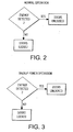
- a signal will be sent to the actuator 18 to cause the locking device 16 to be placed in the unlocked position, as schematically illustrated in Fig. 2 . Therefore, the doors 12 of the elevator car 14 will be permitted to open, either automatically, or manually.
- the energy is blocked by a blocking device 30.
- the blocking device 30 can be a vane or protrusion, for example, which blocks the energy emitted by the energy emitting member 26. It is understood that other methods of blocking the energy emitted could be used, such as interrupting power to the energy emitting member 26 to cease emission of the energy. Additionally, it is understood that the actuator 18 could cause the locking device to be placed in the unlocked position in the absence of a signal from the energy detecting member 24, wherein the energy emitted is blocked when the elevator car 14 is at a building landing.
- the secondary power source 22 then provides power to the actuator 18, the energy detecting member 24, and the energy emitting member 26.
- the door restrictor system 10 operates as previously described for normal operation, and as schematically illustrated in Fig. 3 . It should be noted that if the primary power source 20 is lost, the elevator car may not be operable, and thus caused to remain in the position when the primary power source 20 was lost. The door restrictor system 10 will, however, continue to operate with power from the secondary power source 22 and maintain the doors 12 of the elevator car 14 in a locked or unlocked condition as dictated by the energy detecting member 24 and the actuator 18.
- the secondary power source 22 will be lost or interrupted. If this occurs, and the signal from the energy emitting member 24 is lost, the actuator 18 will cause or permit the locking device 16 to remain in the same position as when power from the secondary power source was lost.
- the locking device 16 in the event the locking device 16 was in the locked position since the elevator car 14 was not at a building landing, the locking device 16 will remain in the locked position.
- the locking device 16 in the event the locking device 16 was in the unlocked position since the elevator car was located at a building landing, the locking device 16 will remain in the unlocked position. Therefore, as a safety device, the locking device 16 will remain in the desired position, either locked or unlocked, until manually altered by an authorized attendant.
- the secondary power source 22 will be activated and the locking device 16 will be maintained in the locked position. Should the secondary power source be lost, the locking device 16 will maintain the present position and the doors 12 of the elevator car 14 will remain locked until manually unlocked by the authorized attendant. However, in the event the elevator car 14 is caused to stop due to a loss of the primary power source 20 at a point at a floor landing, the secondary power source 22 will be activated and the locking device 16 will be maintained in the unlocked position. Should the secondary power source be lost, the locking device 16 will maintain the present position and the doors 12 of the elevator car 14 will remain unlocked.
Landscapes
- Engineering & Computer Science (AREA)
- Automation & Control Theory (AREA)
- Elevator Door Apparatuses (AREA)
- Maintenance And Inspection Apparatuses For Elevators (AREA)
Description
- The present invention relates to an elevator door restrictor and more particularly to a system for preventing an elevator door from being opened unless the elevator car is near a floor or landing.
- When an elevator car is caused to be stalled between floors of a building, the persons trapped in the car should remain in the stalled car until trained assistance arrives to facilitate evacuation. However, oftentimes in such situations, some of the trapped persons may attempt to force the elevator door open in an effort to evacuate. In certain instances the above situation can be extremely dangerous, such as, for example, when the stalled elevator is not at or close to a landing. In such a situation, trapped persons may attempt to jump from the elevator car or climb to a landing. As a result, the trapped persons may fall into the hoistway or elevator shaft, resulting in injury.
- Such accidents may be avoided by a door restrictor system that is effective to prevent the opening of the elevator car from inside of the car if the car is at a location away from a landing at a floor of the building.
- Restrictor systems of the type referred to above generally include a latching or locking member that is typically not accessible from the inside of the elevator car and must be retracted to render the elevator doors operative. These systems may include sensing means which are capable of producing a signal when the elevator car is at or close to a landing and an electrical actuator which retracts the latching or locking member in response to the produced signal.
- The floor sensing means may be an electric switch mounted on the elevator car and actuated by contact with contacting members mounted in the elevator hoistway and more specifically, may be typically mounted on the elevator guide rail and located along the path of travel of the switch. These types of switches tend to deteriorate from wear and are prone to breakage causing continual inspection and frequent replacement.
- In recent years door restrictor systems have included photoelectric sensors for detecting the location of an elevator car in respect of the floor landings in a building. An infrared light emitter and appropriate detector are carried by the car and are directed towards the elevator guide rail of the wall of the hoistway. Spaced apart infrared reflecting members on the guide rail or hoistway wall are disposed to reflect infrared radiation from the emitting member when the elevator car is at or close to a landing. Similar systems have employed optical sensors and magnetic sensors to sense the floor landing and lock, or in certain instances, unlock the elevator doors by means of an associated solenoid.
-
US5,894,911A discloses a door locking system including an electromechanical door lock for elevator car doors. -
US5,655,627 discloses a door restrictor including an electric solenoid mounted to an elevator car. Power can only be applied to the electric solenoid for unlocking when the car is disposed within a floor zone. - These systems have been deemed unacceptable because they default to a certain position when the electrical power is off and associated back-up battery dies.
- Accordingly, some manufacturers have adapted a restrictor system which defaults to a locked state and others default to an unlocked state. Each of these systems results in a state that will be wrong in some instances.
- It would be desirable to produce a bi-stable locking system which can remain in either the locked or unlocked state when electrical power is terminated.
- Consistent and consonant with the present invention, a bi-stable locking system which can remain in either the locked or unlocked state when electrical power is terminated, has surprisingly been discovered.
- The present invention, in the preferred embodiment utilizes battery-backed electronics for sensing the presence of a building landing. Such a system will continue to maintain the mechanism in the correct state, either locked or unlocked, even if the elevator car continues to move. In a power failure, typically, the elevator car will stop moving within ten (10) seconds. After the expiration of the ten (10) second period, the elevator car should move only if an authorized person is on site to physically lift the brake or open a lowering valve. Even if a battery backup were to become completely discharged, the mechanism will remain in the last state (either locked or unlocked) and prevent the elevator car door from being opened until an authorized person takes the appropriate step to move the car or open the car door.
- The door restrictor for preventing opening of an elevator car door by a person inside the car when the car is between unlocking zones at landings along the path of travel of the elevator car comprises:
- a primary source of electrical power;
- a detecting member in electrical communication with the primary source of electrical power; and
- an actuated locking device adapted to selectively lock and unlock the elevator car door, an actuation of the locking device controlled by the detecting member, wherein, in the event of a loss of the primary source of electrical power the locking device remains in the selected locked or unlocked position at the time of the loss of the primary source of electrical power. The bi-stable restrictor further comprises an emitting member, wherein said detecting member receives a signal from said emitting member and actuates said locking device in response to such signal.
- The above, as well as other objects, features, and advantages of the present invention will be understood from the detailed description of the preferred embodiments of the present invention with reference to the accompanying drawings, in which:
-
Fig. 1 is a is a schematic diagram showing a door restrictor system incorporating the features of the invention; -
Fig. 2 is a flow diagram showing the normal operation of the energy detecting member of the door restrictor system illustrated inFig. 1 ; and -
Fig. 3 is a flow diagram showing the backup power operation of the energy detecting member of the door restrictor system illustrated inFig. 1 . - Referring now to the drawings, and particularly
Fig. 1 , there is shown generally at 10 a schematic diagram showing a door restrictor system incorporating the features of the invention. Thedoor restrictor system 10 facilitates selectively locking or unlockingdoors 12 of anelevator car 14 to prevent thedoors 12 from being opened unless theelevator car 14 is in an unlocking zone near a landing. - The
door restrictor system 10 includes alocking device 16 which is typically connected to anactuator 18. Thelocking device 16 can be any conventional locking device such as a spring loaded pin, an electrical or magnetic device, or other mechanical or electromechanical device, for example. It is understood that anyconventional actuator 18 can be used such as a solenoid, for example. Theactuator 18 is typically electrically operated, although it is understood that other actuator types can be used such as pneumatic, for example, without departing from the scope of the invention as defined by independent claims 1 and 15. In the embodiment shown, theactuator 18 is electrically connected to aprimary power source 20 and asecondary power source 22. Thesecondary power source 22 operates as a backup system to theprimary power source 20, and may be a battery backup system or generator backup system, for example. The primary power source is typically the electrical power supplied to the building in which the elevator is housed. - The
actuator 18 is controlled by a signal received from anenergy detecting member 24. Theenergy detecting member 24 can be any conventional detector such as a visible light energy detector, infrared detector, or a magnetic detector, for example. Theenergy detecting member 24 receives and detects energy from anenergy emitting member 26. Theenergy emitting member 26 can be any conventional emitter such as a visible light energy emitter, an infrared emitter, or a magnetic emitter, for example. It is understood that other detecting members can be used such as a mechanical detector, which detects the presence or absence of a structural member, for example, could be used. Such detecting members may or may not require an associated emitting member. In the embodiment shown, theenergy detecting member 24 is mounted on theelevator car 14 and theenergy emitting member 26 is mounted on ashaft wall 28 of the associated elevator hoistway. It is understood that theenergy detecting member 24 can be mounted on theshaft wall 28 and the energy emitting member can be mounted on theelevator car 14 without departing from the scope of the invention as claimed by independent claims 1 and 15. Theenergy detecting member 24 and theenergy emitting member 26 are electrically connected to theprimary power source 20 and thesecondary power source 22. - In operation, the door restrictor system allows the opening of the elevator car doors by normal automatic operation or by occupants of the elevator car only when an energy path is established between the
energy emitting member 26 and theenergy detecting member 24. During normal operation, when theelevator car 14 is at a building landing or floor, energy will be emitted by theenergy emitting member 26 and will be detected by theenergy detecting member 24. Thus, a signal will be sent to theactuator 18 to cause thelocking device 16 to be placed in the unlocked position, as schematically illustrated inFig. 2 . Therefore, thedoors 12 of theelevator car 14 will be permitted to open, either automatically, or manually. When theelevator car 14 is not at a building landing, the energy is blocked by ablocking device 30. The blockingdevice 30 can be a vane or protrusion, for example, which blocks the energy emitted by theenergy emitting member 26. It is understood that other methods of blocking the energy emitted could be used, such as interrupting power to theenergy emitting member 26 to cease emission of the energy. Additionally, it is understood that theactuator 18 could cause the locking device to be placed in the unlocked position in the absence of a signal from theenergy detecting member 24, wherein the energy emitted is blocked when theelevator car 14 is at a building landing. - If the
primary power source 20 is interrupted or lost, thesecondary power source 22 then provides power to theactuator 18, theenergy detecting member 24, and theenergy emitting member 26. Thedoor restrictor system 10 operates as previously described for normal operation, and as schematically illustrated inFig. 3 . It should be noted that if theprimary power source 20 is lost, the elevator car may not be operable, and thus caused to remain in the position when theprimary power source 20 was lost. Thedoor restrictor system 10 will, however, continue to operate with power from thesecondary power source 22 and maintain thedoors 12 of theelevator car 14 in a locked or unlocked condition as dictated by theenergy detecting member 24 and theactuator 18. - It is possible that the
secondary power source 22 will be lost or interrupted. If this occurs, and the signal from theenergy emitting member 24 is lost, theactuator 18 will cause or permit thelocking device 16 to remain in the same position as when power from the secondary power source was lost. Thus, in the event thelocking device 16 was in the locked position since theelevator car 14 was not at a building landing, the lockingdevice 16 will remain in the locked position. Conversely, in the event thelocking device 16 was in the unlocked position since the elevator car was located at a building landing, the lockingdevice 16 will remain in the unlocked position. Therefore, as a safety device, the lockingdevice 16 will remain in the desired position, either locked or unlocked, until manually altered by an authorized attendant. So, for example, in the event theelevator car 14 is caused to stop due to a loss of theprimary power source 20 at a point not at a floor landing, thesecondary power source 22 will be activated and thelocking device 16 will be maintained in the locked position. Should the secondary power source be lost, the lockingdevice 16 will maintain the present position and thedoors 12 of theelevator car 14 will remain locked until manually unlocked by the authorized attendant. However, in the event theelevator car 14 is caused to stop due to a loss of theprimary power source 20 at a point at a floor landing, thesecondary power source 22 will be activated and thelocking device 16 will be maintained in the unlocked position. Should the secondary power source be lost, the lockingdevice 16 will maintain the present position and thedoors 12 of theelevator car 14 will remain unlocked. The following summarizes the various conditions under which thedoor restrictor system 10 may operate: - 1. Normal operation (operating under the primary power source 20) - energy detected as illustrated in
Fig. 2 . - 2. Loss of the
primary power source 20 and operating under the secondary power source 22 - energy detected as illustrated inFig. 3 . - 3. Loss of the
primary power source 20 and loss of the secondary power source 22 - thelocking device 16 remains in last position prior to loss of power as determined by theenergy detecting member 24 and theactuator 18 - From the foregoing description, one ordinarily skilled in the art can easily ascertain the essential characteristics of this invention and can make various changes and modifications to the invention to adapt it to various usages and conditions.
Claims (15)
- A bi-stable restrictor (10) for an elevator car door comprising:a primary source of electrical power (20);a detecting member (24) in electrical communication with said primary source of electrical power (20); anda locking device (16) connected to said detecting member (24) and adapted to selectively move between a locked position to lock an elevator car door and an unlocked position to unlock the elevator car door in response to actuation controlled by said detecting member (24), wherein, in the event of a loss of said primary source of electrical power (20) said locking device (16) remains in the selected locked or unlocked position at the time of the loss of said primary source of electrical power (20), characterized in that the bi-stable restrictor (10) further comprises an emitting member (26), wherein said detecting member (24) receives a signal from said emitting member (26) and actuates said locking device (16) in response to such signal.
- The bi-stable restrictor (10) according to Claim 1, further comprising a secondary source of electrical power (22) provided as a backup for said primary source of electrical power (20), wherein said secondary source of electrical power (22) is connected to and provides power to said detecting member (24) in the event of the loss of said primary source of electrical power (20).
- The bi-stable restrictor (10) according to Claim 2, wherein in the event of the loss of said primary source of electrical power (20), and a loss of said secondary source of electrical power (22), said locking device (16) remains in the selected locked or unlocked position at the time of the loss of said secondary source of electrical power (22).
- The bi-stable restrictor (10) according to Claim 1, wherein said locking device (16) is electrically actuated.
- The bi-stable restrictor (10) according to Claim 4, wherein said locking device (16) is in electrical communication with said primary source of electrical power (20).
- The bi-stable restrictor (10) according to one of the preceding Claims, wherein said detecting member (24) is an energy detecting member (24), said emitting member (26) is an energy emitting member (26), and the signal is energy emitted from said emitting member (26).
- The bi-stable restrictor (10) according to Claim 6, wherein said detecting member (24) causes said locking device (16) to be actuated to the locked position when detecting the energy emitted by said energy emitting member (26).
- The bi-stable restrictor (10) according to Claim 1, further comprising a solenoid (18) operably connected to said locking member and electrically connected to said primary source of electrical power (20), wherein said solenoid (18) selectively causes said locking device (16) to move between the locked and unlocked positions, said solenoid (18) being connected to and controlled by said detecting member (24).
- A bi-stable restrictor (10) for an elevator car door according to Claim 1 further comprising:a secondary source of electrical power (22) provided as a backup for said primary source of electrical power (20);wherein the detecting member (24) is additionally in electrical communication with said secondary source of electrical power (22); andwherein, in the event of a loss of said primary source of electrical power (20) and said secondary source of electrical power (22) said locking device (16) remains in the selected locked or unlocked position at the time of the loss of said secondary source of electrical power (22).
- The bi-stable restrictor (10) according to Claim 9, wherein said locking device (16) is electrically actuated.
- The bi-stable restrictor (10) according to Claim 10, wherein said locking device (16) is in electrical communication with said primary source of electrical power (20) and said secondary source of electrical power (22).
- The bi-stable restrictor (10) according to one of the Claims 9 to 11, wherein said detecting member (24) is an energy detecting member (24), said emitting member (26) is an energy emitting member (26), and the signal is energy emitted from said emitting member (26).
- The bi-stable restrictor (10) according to Claim 12, wherein said detecting member (24) causes said locking device (16) to be actuated to the locked position when detecting the energy emitted by said energy emitting member (26).
- The bi-stable restrictor (10) according to Claim 9, further comprising a solenoid (18) operably connected to said locking member and electrically connected to said primary source of electrical power (20) and said secondary source of electrical power (22), wherein said solenoid (18) selectively causes said locking device (16) switch between the locked and unlocked positions, said solenoid (18) being controlled by said detecting member (24).
- A method of controlling an opening of elevator car doors, comprising the steps of:a) providing a detecting member (24) elevator connected to a primary source of electrical power (20) and producing a signal from the detecting member (24) responsive to a position of an;b) selectively controlling a locking device (16) for elevator car doors with the signal produced by the detecting member (24);c) providing a secondary source of electrical power (22), and operating the secondary source of electrical power (22) as a backup to the primary source of electrical power (20) to supply electrical power to the detecting member (24) upon loss of the primary source of power; andd) causing the locking device (16) to remain in the selected position upon a loss of the secondary source of electrical power (22)e) emitting a second signal from an emitting member (26); andf) the detecting member (24) receiving the second signal and actuating said locking device (16) in response to the second signal.
Applications Claiming Priority (2)
| Application Number | Priority Date | Filing Date | Title |
|---|---|---|---|
| US706783 | 2003-11-12 | ||
| US10/706,783 US7097001B2 (en) | 2003-11-12 | 2003-11-12 | Elevator car door movement restrictor |
Publications (3)
| Publication Number | Publication Date |
|---|---|
| EP1533266A2 EP1533266A2 (en) | 2005-05-25 |
| EP1533266A3 EP1533266A3 (en) | 2008-05-14 |
| EP1533266B1 true EP1533266B1 (en) | 2021-09-08 |
Family
ID=34435636
Family Applications (1)
| Application Number | Title | Priority Date | Filing Date |
|---|---|---|---|
| EP04025859.2A Ceased EP1533266B1 (en) | 2003-11-12 | 2004-10-30 | Door restrictor |
Country Status (7)
| Country | Link |
|---|---|
| US (1) | US7097001B2 (en) |
| EP (1) | EP1533266B1 (en) |
| JP (1) | JP5562511B2 (en) |
| KR (1) | KR101211452B1 (en) |
| CN (1) | CN100368276C (en) |
| BR (1) | BRPI0404944A (en) |
| CA (1) | CA2487234C (en) |
Families Citing this family (17)
| Publication number | Priority date | Publication date | Assignee | Title |
|---|---|---|---|---|
| ATE552203T1 (en) * | 2004-09-27 | 2012-04-15 | Otis Elevator Co | ELEVATOR DOOR LOCK SENSOR DEVICE |
| US9695015B1 (en) | 2005-12-28 | 2017-07-04 | James Marinelli | Elevator door safety lock system |
| EP2234914B1 (en) * | 2007-12-18 | 2019-03-13 | Inventio AG | Locking system for a lift door |
| US8960372B2 (en) * | 2010-07-08 | 2015-02-24 | Thyssenkrupp Elevator Corporation | Elevator car door interlock |
| EP2803615B1 (en) * | 2013-05-17 | 2019-01-23 | KONE Corporation | Arrangement and method for condition monitoring of automatic door |
| EP3004717B1 (en) * | 2013-05-28 | 2021-07-07 | Inventio AG | Elevator door with a door contact switch |
| US9837860B2 (en) * | 2014-05-05 | 2017-12-05 | Witricity Corporation | Wireless power transmission systems for elevators |
| CN106573760A (en) * | 2014-08-22 | 2017-04-19 | 奥的斯电梯公司 | Hoistway door locking system and method of controlling access to an elevator shaft |
| CN107848736B (en) * | 2015-07-30 | 2023-05-30 | 因温特奥股份公司 | Latch system for car doors |
| US10252884B2 (en) * | 2016-04-05 | 2019-04-09 | Otis Elevator Company | Wirelessly powered elevator electronic safety device |
| ES2921228T3 (en) | 2017-07-12 | 2022-08-22 | Otis Elevator Co | locking device |
| CN109835799B (en) * | 2019-04-13 | 2021-01-05 | 广东联合富士电梯有限公司 | Elevator intelligent door lock loop control method |
| CN111977494B (en) * | 2020-09-10 | 2021-12-31 | 伟龙意程智能科技(江苏)有限公司 | Self-locking elevator car |
| EP4095081A1 (en) * | 2021-05-28 | 2022-11-30 | Otis Elevator Company | Elevator systems |
| CN113562578B (en) * | 2021-09-24 | 2021-12-07 | 伊萨智能电梯有限公司 | Intelligent elevator capable of achieving safety identification |
| FR3138656A1 (en) * | 2022-08-03 | 2024-02-09 | Sodimas | Safe maintenance elevator installation |
| KR102603954B1 (en) * | 2023-07-26 | 2023-11-21 | 주식회사 한림기업 | Double safety system for hall door of freight elevator |
Family Cites Families (19)
| Publication number | Priority date | Publication date | Assignee | Title |
|---|---|---|---|---|
| US3706357A (en) * | 1970-03-30 | 1972-12-19 | Joseph Elmer Simpson | Elevator emergency actuator and rescue unit |
| JPS56103077A (en) * | 1980-01-21 | 1981-08-17 | Mitsubishi Electric Corp | Emergency driving device for elevator |
| US4529065A (en) * | 1983-10-21 | 1985-07-16 | Westinghouse Electric Corp. | Elevator system |
| JPS60223770A (en) * | 1984-04-18 | 1985-11-08 | 株式会社日立製作所 | Detector for position of elevator |
| JPH04182287A (en) * | 1990-11-16 | 1992-06-29 | Mitsubishi Electric Corp | Emergency operating device for elevator |
| JPH04277182A (en) * | 1991-03-04 | 1992-10-02 | Hitachi Building Syst Eng & Service Co Ltd | Control device for elevator |
| JPH0567779U (en) * | 1991-04-05 | 1993-09-10 | 株式会社新興製作所 | Electric lock control device |
| JPH04322186A (en) | 1991-04-22 | 1992-11-12 | Hitachi Ltd | Motor-operated door device |
| JPH0680363A (en) * | 1992-09-03 | 1994-03-22 | Hitachi Building Syst Eng & Service Co Ltd | Car door lock device of elevator |
| JPH06271218A (en) * | 1993-03-19 | 1994-09-27 | Mitsubishi Denki Bill Techno Service Kk | Elevator landing level detector |
| TW348169B (en) * | 1994-11-15 | 1998-12-21 | Inventio Ag | Evacuation system for a lift cage |
| US5655627A (en) * | 1995-08-08 | 1997-08-12 | Advanced Microcontrols, Inc. | Elevator door restrictor |
| JPH09278306A (en) * | 1996-04-10 | 1997-10-28 | Otis Elevator Co | Cargo initial position recognizing device for elevator |
| JPH10167638A (en) | 1996-12-16 | 1998-06-23 | Hitachi Ltd | Braking device for door |
| US5894911A (en) * | 1997-07-11 | 1999-04-20 | Otis Elevator Company | Car door locking system |
| US5918705A (en) * | 1997-11-10 | 1999-07-06 | Friend; Jeff | Building elevator door restrictor |
| US6196355B1 (en) * | 1999-03-26 | 2001-03-06 | Otis Elevator Company | Elevator rescue system |
| JP3920528B2 (en) * | 2000-04-07 | 2007-05-30 | 株式会社日立ビルシステム | Elevator position detection device |
| JP2001316052A (en) * | 2000-05-02 | 2001-11-13 | Mitsubishi Electric Corp | Position detecting device for elevator |
-
2003
- 2003-11-12 US US10/706,783 patent/US7097001B2/en active Active
-
2004
- 2004-10-29 JP JP2004315238A patent/JP5562511B2/en not_active Expired - Fee Related
- 2004-10-30 EP EP04025859.2A patent/EP1533266B1/en not_active Ceased
- 2004-11-10 CA CA2487234A patent/CA2487234C/en active Active
- 2004-11-10 BR BR0404944-6A patent/BRPI0404944A/en not_active Application Discontinuation
- 2004-11-10 CN CNB2004100929014A patent/CN100368276C/en active Active
- 2004-11-11 KR KR1020040091877A patent/KR101211452B1/en not_active IP Right Cessation
Also Published As
| Publication number | Publication date |
|---|---|
| CN100368276C (en) | 2008-02-13 |
| JP2005162483A (en) | 2005-06-23 |
| EP1533266A3 (en) | 2008-05-14 |
| JP5562511B2 (en) | 2014-07-30 |
| US20050098389A1 (en) | 2005-05-12 |
| KR101211452B1 (en) | 2012-12-12 |
| CN1616338A (en) | 2005-05-18 |
| US7097001B2 (en) | 2006-08-29 |
| BRPI0404944A (en) | 2005-07-19 |
| KR20050045910A (en) | 2005-05-17 |
| CA2487234C (en) | 2011-08-09 |
| CA2487234A1 (en) | 2005-05-12 |
| EP1533266A2 (en) | 2005-05-25 |
Similar Documents
| Publication | Publication Date | Title |
|---|---|---|
| EP1533266B1 (en) | Door restrictor | |
| EP2163502B1 (en) | Elevator with a semiconductor switch for brake control | |
| JP6971022B2 (en) | Elevator car movement control method and elevator system | |
| KR101624825B1 (en) | Safety device for elevator | |
| EP0508403B1 (en) | Low speed elevator car safety circuit | |
| US5894911A (en) | Car door locking system | |
| KR100319334B1 (en) | Elevator door tampering protection system | |
| CN112135787B (en) | Safety switching system and method for switching an elevator installation between a normal operating mode and an inspection operating mode | |
| EP3687929B1 (en) | Safe elevator shaft and car roof access | |
| EP2020395B1 (en) | Actuation process and device in an emergency situation in elevator apparatuses | |
| US5183978A (en) | Elevator governor rope block actuation in low speed emergency situations | |
| EP1524234B1 (en) | Elevator system | |
| WO2017017702A1 (en) | Lock strike plate provided with an emergency unlocking system, and lock-ing device comprising said lock strike plate | |
| JP2002154774A (en) | Door device for elevator | |
| GB2206331A (en) | Elevator car door locking mechanism | |
| US1531428A (en) | Elevator control system and shaft-door lock | |
| JPH0680363A (en) | Car door lock device of elevator | |
| US20240051793A1 (en) | Elevator pit maintenance systems | |
| JP2004107026A (en) | Elevator controller | |
| JP2003292273A (en) | Elevator cage door apparatus with locking apparatus | |
| US20230242373A1 (en) | Elevator systems with improved monitoring | |
| US20230146745A1 (en) | Avoiding entrapment in an elevator | |
| JP2019142666A (en) | Safety device for hydraulic elevator | |
| JPH0859123A (en) | Earthquake emergency device on hydraulic elevator |
Legal Events
| Date | Code | Title | Description |
|---|---|---|---|
| PUAI | Public reference made under article 153(3) epc to a published international application that has entered the european phase |
Free format text: ORIGINAL CODE: 0009012 |
|
| AK | Designated contracting states |
Kind code of ref document: A2 Designated state(s): AT BE BG CH CY CZ DE DK EE ES FI FR GB GR HU IE IT LI LU MC NL PL PT RO SE SI SK TR |
|
| AX | Request for extension of the european patent |
Extension state: AL HR LT LV MK |
|
| REG | Reference to a national code |
Ref country code: HK Ref legal event code: DE Ref document number: 1077559 Country of ref document: HK |
|
| PUAL | Search report despatched |
Free format text: ORIGINAL CODE: 0009013 |
|
| AK | Designated contracting states |
Kind code of ref document: A3 Designated state(s): AT BE BG CH CY CZ DE DK EE ES FI FR GB GR HU IE IT LI LU MC NL PL PT RO SE SI SK TR |
|
| AX | Request for extension of the european patent |
Extension state: AL HR LT LV MK |
|
| 17P | Request for examination filed |
Effective date: 20081103 |
|
| AKX | Designation fees paid |
Designated state(s): AT CH DE FR GB LI |
|
| STAA | Information on the status of an ep patent application or granted ep patent |
Free format text: STATUS: EXAMINATION IS IN PROGRESS |
|
| 17Q | First examination report despatched |
Effective date: 20170713 |
|
| STAA | Information on the status of an ep patent application or granted ep patent |
Free format text: STATUS: EXAMINATION IS IN PROGRESS |
|
| GRAP | Despatch of communication of intention to grant a patent |
Free format text: ORIGINAL CODE: EPIDOSNIGR1 |
|
| STAA | Information on the status of an ep patent application or granted ep patent |
Free format text: STATUS: GRANT OF PATENT IS INTENDED |
|
| INTG | Intention to grant announced |
Effective date: 20210422 |
|
| REG | Reference to a national code |
Ref country code: HK Ref legal event code: WD Ref document number: 1077559 Country of ref document: HK |
|
| GRAS | Grant fee paid |
Free format text: ORIGINAL CODE: EPIDOSNIGR3 |
|
| GRAA | (expected) grant |
Free format text: ORIGINAL CODE: 0009210 |
|
| STAA | Information on the status of an ep patent application or granted ep patent |
Free format text: STATUS: THE PATENT HAS BEEN GRANTED |
|
| REG | Reference to a national code |
Ref country code: DE Ref legal event code: R081 Ref document number: 602004055020 Country of ref document: DE Owner name: INVENTIO AG, CH Free format text: FORMER OWNER: INVENTIO AG, HERGISWIL, NIDWALDEN, CH |
|
| AK | Designated contracting states |
Kind code of ref document: B1 Designated state(s): AT CH DE FR GB LI |
|
| REG | Reference to a national code |
Ref country code: GB Ref legal event code: FG4D |
|
| REG | Reference to a national code |
Ref country code: CH Ref legal event code: EP Ref country code: AT Ref legal event code: REF Ref document number: 1428430 Country of ref document: AT Kind code of ref document: T Effective date: 20210915 |
|
| REG | Reference to a national code |
Ref country code: DE Ref legal event code: R096 Ref document number: 602004055020 Country of ref document: DE |
|
| REG | Reference to a national code |
Ref country code: AT Ref legal event code: MK05 Ref document number: 1428430 Country of ref document: AT Kind code of ref document: T Effective date: 20210908 |
|
| PG25 | Lapsed in a contracting state [announced via postgrant information from national office to epo] |
Ref country code: AT Free format text: LAPSE BECAUSE OF FAILURE TO SUBMIT A TRANSLATION OF THE DESCRIPTION OR TO PAY THE FEE WITHIN THE PRESCRIBED TIME-LIMIT Effective date: 20210908 |
|
| REG | Reference to a national code |
Ref country code: CH Ref legal event code: PL |
|
| REG | Reference to a national code |
Ref country code: DE Ref legal event code: R097 Ref document number: 602004055020 Country of ref document: DE |
|
| PLBE | No opposition filed within time limit |
Free format text: ORIGINAL CODE: 0009261 |
|
| STAA | Information on the status of an ep patent application or granted ep patent |
Free format text: STATUS: NO OPPOSITION FILED WITHIN TIME LIMIT |
|
| REG | Reference to a national code |
Ref country code: DE Ref legal event code: R084 Ref document number: 602004055020 Country of ref document: DE |
|
| 26N | No opposition filed |
Effective date: 20220609 |
|
| REG | Reference to a national code |
Ref country code: DE Ref legal event code: R084 Ref document number: 602004055020 Country of ref document: DE |
|
| PG25 | Lapsed in a contracting state [announced via postgrant information from national office to epo] |
Ref country code: LI Free format text: LAPSE BECAUSE OF NON-PAYMENT OF DUE FEES Effective date: 20211031 Ref country code: CH Free format text: LAPSE BECAUSE OF NON-PAYMENT OF DUE FEES Effective date: 20211031 |
|
| PGFP | Annual fee paid to national office [announced via postgrant information from national office to epo] |
Ref country code: FR Payment date: 20221024 Year of fee payment: 19 |
|
| PGFP | Annual fee paid to national office [announced via postgrant information from national office to epo] |
Ref country code: GB Payment date: 20221018 Year of fee payment: 19 Ref country code: DE Payment date: 20221028 Year of fee payment: 19 |
|
| REG | Reference to a national code |
Ref country code: DE Ref legal event code: R119 Ref document number: 602004055020 Country of ref document: DE |
|
| GBPC | Gb: european patent ceased through non-payment of renewal fee |
Effective date: 20231030 |
|
| PG25 | Lapsed in a contracting state [announced via postgrant information from national office to epo] |
Ref country code: GB Free format text: LAPSE BECAUSE OF NON-PAYMENT OF DUE FEES Effective date: 20231030 |
|
| PG25 | Lapsed in a contracting state [announced via postgrant information from national office to epo] |
Ref country code: GB Free format text: LAPSE BECAUSE OF NON-PAYMENT OF DUE FEES Effective date: 20231030 Ref country code: FR Free format text: LAPSE BECAUSE OF NON-PAYMENT OF DUE FEES Effective date: 20231031 Ref country code: DE Free format text: LAPSE BECAUSE OF NON-PAYMENT OF DUE FEES Effective date: 20240501 |