EP2803615B1 - Arrangement and method for condition monitoring of automatic door - Google Patents
Arrangement and method for condition monitoring of automatic door Download PDFInfo
- Publication number
- EP2803615B1 EP2803615B1 EP13168178.5A EP13168178A EP2803615B1 EP 2803615 B1 EP2803615 B1 EP 2803615B1 EP 13168178 A EP13168178 A EP 13168178A EP 2803615 B1 EP2803615 B1 EP 2803615B1
- Authority
- EP
- European Patent Office
- Prior art keywords
- door
- motor
- elevator
- automatic
- control system
- Prior art date
- Legal status (The legal status is an assumption and is not a legal conclusion. Google has not performed a legal analysis and makes no representation as to the accuracy of the status listed.)
- Active
Links
Images

Classifications
-
- B—PERFORMING OPERATIONS; TRANSPORTING
- B66—HOISTING; LIFTING; HAULING
- B66B—ELEVATORS; ESCALATORS OR MOVING WALKWAYS
- B66B5/00—Applications of checking, fault-correcting, or safety devices in elevators
- B66B5/0006—Monitoring devices or performance analysers
- B66B5/0018—Devices monitoring the operating condition of the elevator system
-
- B—PERFORMING OPERATIONS; TRANSPORTING
- B66—HOISTING; LIFTING; HAULING
- B66B—ELEVATORS; ESCALATORS OR MOVING WALKWAYS
- B66B5/00—Applications of checking, fault-correcting, or safety devices in elevators
- B66B5/0006—Monitoring devices or performance analysers
-
- B—PERFORMING OPERATIONS; TRANSPORTING
- B66—HOISTING; LIFTING; HAULING
- B66B—ELEVATORS; ESCALATORS OR MOVING WALKWAYS
- B66B13/00—Doors, gates, or other apparatus controlling access to, or exit from, cages or lift well landings
- B66B13/02—Door or gate operation
- B66B13/14—Control systems or devices
- B66B13/143—Control systems or devices electrical
- B66B13/146—Control systems or devices electrical method or algorithm for controlling doors
Definitions
- the invention relates to an arrangement and a method for monitoring the condition of an automatic door in an elevator, preferably an elevator suitable for transportation of passengers and/or goods, or in a building.
- An automatic door arrangement in a normal operational condition involves a certain amount of friction-induced friction force that resists motion.
- the information may be utilized for monitoring the performance and condition of the system.
- An automatic door of an elevator consists of a car door moving with the car and operated by a door operator, which comprises a door motor and a door mechanism for moving one or more door leaves in their location horizontally, and landing doors which the car door captures along while on that floor.
- An elevator door of this kind which slides automatically on a horizontal rail, is a part on which forces from various directions are exerted and which is in contact, both at its upper and lower edges, with the rail that keeps the door movement in its path. The friction force also resists the movement of the automatic door.
- the operation of the door may be disturbed, when a sufficient amount of dirt is accumulated on the door slide rail on the threshold of the elevator car. Due to this physical obstacle, the force resisting the motion of the door may become so high that, eventually, a door control system is no longer able to open or close the door.
- a large part of elevator failures result from malfunctions in the automatic door of the elevator. Some of the door faults appear in such a way that it becomes heavier for the door motor to move the door. Because the door movement is controlled by a feedback adjuster that corrects changes of this type in the system, as long as there will be enough torque and power in the motor, the operation of the door appears fully normal outwards. Thus, in a feedback system there may be a failure in the making, or the system may originally have been mounted, adjusted or parametrized in a wrong way, but because of the feedback it will not appear outwards for a long time.
- Publication EP 1713711 B1 discloses a method for monitoring the condition of an automatic door in a building, which method is based on force balances in a model for the door and on adapting model parameters using an optimization method.
- the method requires a current to torque function of a door motor that converts the current of the door to a torque produced by the door, transmission ratio of the door motor and the relating mechanism, by which the torque of the motor is converted to a linear force that moves the door leaves, and a force factor of a spring in a landing door closing device, or, if the closing device is a weight, mass of the weight.
- the current of the door motor (system excitation) and acceleration of a door leaf (system response) are to be collected to a buffer of the control system typically at a sampling frequency of 100 Hz during a door operating cycle.
- a buffer of the control system typically at a sampling frequency of 100 Hz during a door operating cycle.
- the parameters of the force model such that the model produces as well as possible the same acceleration curve as that in the measured data.
- the frictions of the door After fitting there are known the frictions of the door, the reduced masses of the door and the operational condition of the closing device.
- initial data there are required the type of the motor and the current to torque curve of the motor, the type of the closing device, the mass of the weight and the elastic constant of the spring.
- Prior art has also been disclosed in documents US2011/0016971 A1 and US2008/0179143 A1 .
- the object of the invention is to solve the above-described prior art problems.
- a further object is to solve problems to be set forth later on in the description of the invention.
- the object is thus to provide an improved condition monitoring arrangement of an automatic door and an improved method for monitoring the condition of an automatic door, preferably in an elevator suitable for transportation of passengers and/or goods, or in connection with an automatic door in a building.
- the method for monitoring the condition of the automatic door in accordance with the invention it is possible to reduce malfunctions, to enhance installation and maintenance processes and to improve user safety.
- the elevators will be of more uniform quality, which reduces the number of premature failures.
- the method for monitoring the condition of the automatic door requires little computing resources and is easy to integrate with the control system for the automatic door and the elevator. With the condition monitoring parameters obtained by the method it is possible to improve and enhance the installation and service processes, to reduce fault alarms and to improve passenger safety.
- the present method is unable to make a distinction between the reasons for increased friction, in other words, to diagnose a source of failure, an anomaly can be detected, however, and it can be deduced whether it is a car door of the elevator that is concerned, whereby friction increases on all floors, or whether it is a landing door, whereby friction increases only on a given floor.
- the service process may decide how to react to the detected event, by taking a measure either immediately or on a next, scheduled service call.
- An important safety device is the spring- or weight-operated closing device for the landing door of the elevator.
- the open landing door, or the door with the lock open, must tend to close by itself. Naturally this is to prevent people from falling into the elevator shaft and serious consequences resulting therefrom, even death, in the worst case.
- Calculation of parameters, and preparation of a condition evaluation or a service need may be performed either in a door operator control system, an elevator control system, a separate measuring system, a local user interface, a remote user interface or on a remote server.
- the door operator control system refers to a device that controls the door motor.
- the door operator control system includes a frequency converter or another controller that controls motion of an electric motor.
- the door operator motor controller includes a micro controller or another programmable unit that is able to control the motor, to carry out measurements, to perform computational operations and to communicate measurements or results of computational operations to the elevator control system and to receive commands from the elevator control system so as to move the door.
- the door operator control system of a building may also make a decision itself on the actuation of the door, for instance, on the basis of information from a proximity sensor in the vicinity of the door.
- the elevator control system refers to a device that controls the operation of the elevator.
- the elevator control system commands the door operator control system to move the door (e.g. door open or door closed).
- the door operator control system performs a measurement on the voltage and current of the motor.
- the door operator control system typically knows the open/closed state information of the door.
- the arrangement of the invention for monitoring the operational condition of an automatic door in an elevator, in particular a passenger and/or goods transportation elevator, or in a building comprises:
- said means for determining the mechanical energy of the door motor shaft of the automatic door comprise:
- said means for defining the operational condition of the door mechanism and/or the closing device of the automatic door comprise means for determining the magnitude of the friction force and/or the amount of potential energy stored in the door mechanism, during an operating cycle.
- the means for defining the operational condition of the closing device and the door mechanism of the automatic door comprise a condition monitoring algorithm, which is implemented in
- the local user interface or the remote user interface of the automatic door is integrated to form part of the elevator control system.
- the door operator control system is integrated to form part of the elevator control system.
- the means for determining the state information of the automatic door during the operating cycle comprise:
- said door motor is a DC or AC motor, preferably a single-phase or a multi-phase electric motor.
- the door motor, the encoder measuring the travel of the door and the door switches are connected directly to the elevator control system through buses.
- the door motor, the encoder measuring the travel of the door and the door switches are connected through buses to a door control card, which is connected to the elevator control system through a bus.
- the automatic door comprises an elevator car door and an elevator landing door.
- condition monitoring algorithm is implemented by a door operator.
- condition monitoring algorithm is implemented in the elevator control system, if the control system of the door operator supplies sufficient measurement data to the control system.
- condition monitoring algorithm is implemented by separate measuring equipment that measures the open/closed state of the door as well as the voltage and current of the motor, and calculates the friction force and the potential energy stored in the closing device.
- condition monitoring algorithm is also implemented by a separate device, capable of computation, that receives sufficient measurement data from the door operator.
- condition monitoring algorithm may also be implemented by a separate device, capable of computation, that receives sufficient measurement data from the elevator control system.
- the local user interface and the remote user interface are an integrated part of the elevator control system.
- the door operator is an integrated part of the elevator control system.
- the information 'door open/closed' is produced by switches of the type of mechanical on/off or Hall sensor-based on/off or Reed relay on/off or optical on/off, or an inductive proximity sensor or a capacitive proximity sensor.
- the information 'door open/closed' is also produced by sensors of another type, such as a location sensor, e.g. an encoder, a laser or a potentiometer, or a velocity sensor, e.g. a tachometer or an accelerometer.
- sensors of another type such as a location sensor, e.g. an encoder, a laser or a potentiometer, or a velocity sensor, e.g. a tachometer or an accelerometer.
- the arrangement and the method of the invention for monitoring the condition of an automatic door solve the problems associated with the known solutions and produce a larger part of the information, such as the frictions and the condition of the closing device, required by the control system.
- the door comprising one or more door leaves, a door mechanism and/or a closing device, and performed at least the following steps of:
- the elastic constant or the mass of a weight of the closing device is determined from the amount of the potential energy stored in the door mechanism.
- the door state information during the operating cycle comprises information on when the door is closed, preferably completely closed before opening, when the door is open, preferable completely open, and when the door is closed, preferably completely closed after opening.
- the mechanical power of the door motor shaft is determined by measuring the current and voltage of the door motor during the operating cycle, by calculating the electric power of the door motor and by subtracting from the electric power the internal dissipation powers of the door motor, which include power losses caused by coil resistance of the motor.
- the mechanical power of the door motor shaft is determined on the basis of the angular speed and torque of the door motor, preferably by measuring the torque with a force or torque sensor, or by measuring the current of the door motor and using a current to torque function of the door motor to estimate the torque.
- a door opening width which is an elevator system parameter to be configured in connection with delivery.
- the door opening width may also be advantageously measured by means of an encoder or another corresponding device during use.
- the method does not require initial information on the properties of the door motor, nor on the elastic constant or the mass of a weight of the closing device.
- the method is robust.
- the method and arrangement for monitoring the condition of an automatic door is easy to implement in an elevator control system with a limited availability to memory and computational capacity.
- Figure 1 is a schematic side view of an arrangement for monitoring the condition of an automatic door in an elevator in accordance with an embodiment, the arrangement comprising an elevator car 1, a counterweight 2 and a suspension rope system 3 whose ropes interconnect said elevator car 1 and counterweight 2.
- the elevator car 1 and the counterweight 2 are arranged for being moved by exerting vertical force on at least the elevator car 1 or the counterweight 2 by means of elements M, 6, 3.
- the suspension rope system 3 comprises one or more ropes.
- the elevator is preferably a passenger and/or goods elevator that is mounted to travel in a shaft S in a building.
- means for exerting the force on at least the elevator car 1 or the counterweight 2 comprise the suspension rope system 3, which is connected to the elevator car and/or the counterweight, and a hoisting mechanism M, which comprises means for moving the suspension rope system 3, which means preferably comprise a drive device, e.g. a motor, and a drive member 6 to be rotated, preferably a drive wheel.
- the hoisting mechanism M is placed in the vicinity of the upper end of the path of the elevator car 1.
- the hoisting mechanism M is thus in power transmission connection with the elevator car 1 and the counterweight 2 through the suspension rope system 3, the hoisting mechanism M being arranged, in particular, to exert upward pulling force on the elevator car 1 or the counterweight 2 through the suspension rope system 3.
- a compensation rope 4 to balance an imbalance torque caused by the suspension ropes.
- the car doors 7 and the landing doors 10 are on the same wall with the elevator car 1.
- the hoisting mechanism M may also be placed in the vicinity of the lower end of the path of the elevator car 1.
- the hoisting mechanism M is thus in power transmission connection with the elevator car 1 and the counterweight 2 through the hoisting rope system 4, the hoisting mechanism M being arranged, in particular, to exert downward pulling force on the elevator car 1 or the counterweight 2 through the hoisting rope system 4.
- a rope in the suspension rope system 3 need not transmit, through the outer surface of the rope, forces in the longitudinal direction of the rope, and no shearing forces in the direction of the surface are exerted on the load-bearing part of the rope or on an optional coating thereon.
- the ropes of the suspension rope system 3 may be suspended by deflecting about a rope pulley, which need not be a driven drive wheel.
- the elevator comprises a rope pulley 5 and/or rope pulleys in the vicinity of the upper and/or lower end of the path of the elevator car 1.
- Supporting on the rope pulley 5, for instance, a rope or ropes of the suspension rope system 3 carry the elevator car 1 and the counterweight 2.
- this is implemented by 1:1 suspension, whereby the ropes of the suspension rope system 3 are connected by the first end to the elevator car 1 and by the second end to the counterweight 2.
- the suspension ratio may also be other than that, e.g.
- the rope pulleys are non-driven rope pulleys, and consequently the upper parts of the elevator may also be provided spacious.
- the rope pulleys are in an elevator shaft S, whereby no separate engine room is needed.
- Figure 2 shows schematically an arrangement for monitoring the condition of an automatic door in accordance with an embodiment, in which the actuators and the sensors of the automatic door are connected directly to the control system of the elevator.
- the object is to provide a reliable and advantageous method for monitoring the condition of automatic doors in an elevator or a building.
- the arrangement of Figure 2 for monitoring the condition of an automatic door in an elevator comprises an elevator door motor 12, an encoder 14, or the like, measuring a door travel, door switches 13, which comprise 'door open' or 'door closed' switches, electric wiring 15 for the elevator or building door 7 and the motor 12.
- the door motor 12 is a DC motor or an AC motor, preferably a single-phase or a multi-phase electric motor.
- Signals provided by the encoder 14 measuring the door travel pass along a bus 16. The travel may also be measured in some other way than with the encoder.
- the signals of the switches 13 pass along a bus 17.
- the door control system 9 of the elevator or the building controls the door motor 12 and reads the signals 16 and 17.
- Figure 3 shows schematically the arrangement for monitoring the condition of the automatic door in accordance with an embodiment, in which actuators and sensors of the door are connected to a door control card 8, which is connected to an elevator control system 9.
- the arrangement of Figure 3 for monitoring the condition of an automatic door in an elevator comprises an elevator door motor 12, an encoder 14, or the like, measuring a door travel, door switches 13, which comprise 'door open' or 'door closed' switches, electric wiring 15 for the elevator or building door 7 and the motor 12.
- the door motor 12 is a DC motor or an AC motor.
- Signals provided by the encoder 14 measuring the door travel pass along a bus 16. The travel may also be measured in some other way than with the encoder.
- the signals of the switches 13 pass along a bus 17.
- the door motor 12, the encoder 14 measuring the door travel, and the door switches 13 are connected to a door control card 8, which is connected to an elevator control system 9 along a bus 11.
- the door control system 9 of the elevator or the building controls the door control card 8, which controls the door motor 12 and reads the signals 16 and 17.
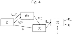
- Figure 4 is a block diagram of an arrangement for monitoring the condition of an automatic door in accordance with an embodiment.
- the current of the door motor 12 as a function I M (t) of time t
- the voltage of the door motor 12 as a function U M (t) of time t
- the electric power P(t) used by the electric motor 12 is consumed by copper and iron losses of the door motor 12 and mechanical work needed for moving the door 7.
- the method measures the current I M (t) and voltage U M (t) of the door motor 12 and calculates a cumulative quantity, i.e. energy supplied to the door motor 12.
- Mechanical energy E MS used for a door open/closed cycle is an indication of the basic adjustments and operational condition of the door. When this energy is distributed onto a travelled distance d, the energy consumed can be normalized per metre travelled. This is called a friction force resisting motion F ⁇ , the unit thereof being Newton N.
- k S is a springback factor of the closing spring.
- the opening and closing speeds of the door 7 are different. For reasons of impact energy and comfort the opening of the door 7 may usually take place faster than the closing.
- Formulae (1) and (2), used in this manner, involve an assumption that most of the friction is velocity-independent Coulomb friction and the share of velocity-dependent bearing frictions may be incorporated in this friction without any significant error.
- k S is the effective elastic constant of the closing device with the assumption that the travel of the spring is the same as the nominal travel of the door.
- the spring is connected to a door leaf having the shortest travel.
- the number of leaves is preferably two or three.
- the motor converts the input electric power P ME to mechanical shaft power P MS .
- P ME the electric power supplied into the motor
- P MS the mechanical shaft power of the motor
- P MML the internal mechanical friction losses of the motor and gear system optionally integrated therewith
- P cu is the losses produced in the motor circuitry, i.e. so-called copper losses
- P fe is the losses produced in the magnetic circuits of the motor, i.e. so-called iron losses.
- I m is the motor current and R S ( T ) is the resistance of the motor circuit at actual temperature T of the motor.
- the resistance of the copper winding and current losses therewith vary along with the temperature, so the resistance of the winding is to be measured separately for each door operation. Another matter that supports online measurement of the resistance is that it enables omission of one parameter to be set in advance.
- U M is the voltage acting over the motor circuit.
- the spring of the closing device is connected to a slower moving door and the elastic constant k S is calculated considering the transmission R.
- the method is capable of reliably detecting both the operational frictions of the door and the operational condition of the closing device of the landing door.
- the elevator is an elevator suitable for transporting passengers and/or goods, which is mounted in a building to move vertically, or at least substantially vertically, preferably on the basis of landing and/or car calls.
- the elevator comprises one or more elevator units and the elevator car preferably comprises an interior space that is most preferably suitable for receiving a passenger or several passengers.
- the elevator comprises preferably at least two, preferably more, landings to be served.
- inventive embodiments are also disclosed in the specification and drawings of this application.
- inventive contents of the application may also be defined in ways other than those described in the following claims.
- inventive contents may also consist of several separate inventions, particularly if the invention is examined in the light of expressed or implicit sub-tasks or in view of obtained benefits or benefit groups. In such a case, some of the definitions contained in the following claims may be unnecessary in view of the separate inventive ideas.
- Features of the different embodiments of the invention may be applied to other applications within the scope of the basic inventive idea.
- the arrangement of the invention is characterized by what is disclosed in the characterizing part of claim 1.
- the method of the invention is characterized by what is disclosed in the characterizing part of claim 12.
- Other embodiments of the invention are characterized by what is disclosed in the other claims.
- inventive embodiments are also disclosed in the specification and drawings of this application.
- the inventive contents of the application may also be defined in ways other than those described in the following claims.
- the inventive contents may also consist of several separate inventions, particularly if the invention is examined in the light of expressed or implicit sub-tasks or in view of obtained benefits or benefit groups. In such a case, some of the definitions contained in the following claims may be unnecessary in view of the separate inventive ideas.
- Features of the different embodiments of the invention may be applied to other embodiments within the scope of the basic inventive idea.
Description
- The invention relates to an arrangement and a method for monitoring the condition of an automatic door in an elevator, preferably an elevator suitable for transportation of passengers and/or goods, or in a building.
- An automatic door arrangement in a normal operational condition involves a certain amount of friction-induced friction force that resists motion. In case the magnitudes of the friction forces in the door arrangement can be found out by measurement or computationally, the information may be utilized for monitoring the performance and condition of the system.
- An automatic door of an elevator consists of a car door moving with the car and operated by a door operator, which comprises a door motor and a door mechanism for moving one or more door leaves in their location horizontally, and landing doors which the car door captures along while on that floor. An elevator door of this kind, which slides automatically on a horizontal rail, is a part on which forces from various directions are exerted and which is in contact, both at its upper and lower edges, with the rail that keeps the door movement in its path. The friction force also resists the movement of the automatic door. The operation of the door may be disturbed, when a sufficient amount of dirt is accumulated on the door slide rail on the threshold of the elevator car. Due to this physical obstacle, the force resisting the motion of the door may become so high that, eventually, a door control system is no longer able to open or close the door.
- A large part of elevator failures result from malfunctions in the automatic door of the elevator. Some of the door faults appear in such a way that it becomes heavier for the door motor to move the door. Because the door movement is controlled by a feedback adjuster that corrects changes of this type in the system, as long as there will be enough torque and power in the motor, the operation of the door appears fully normal outwards. Thus, in a feedback system there may be a failure in the making, or the system may originally have been mounted, adjusted or parametrized in a wrong way, but because of the feedback it will not appear outwards for a long time.
- Publication
EP 1713711 B1 discloses a method for monitoring the condition of an automatic door in a building, which method is based on force balances in a model for the door and on adapting model parameters using an optimization method. As initial data the method requires a current to torque function of a door motor that converts the current of the door to a torque produced by the door, transmission ratio of the door motor and the relating mechanism, by which the torque of the motor is converted to a linear force that moves the door leaves, and a force factor of a spring in a landing door closing device, or, if the closing device is a weight, mass of the weight. In the method, the current of the door motor (system excitation) and acceleration of a door leaf (system response) are to be collected to a buffer of the control system typically at a sampling frequency of 100 Hz during a door operating cycle. To this excitation/response data set are fitted the parameters of the force model such that the model produces as well as possible the same acceleration curve as that in the measured data. After fitting there are known the frictions of the door, the reduced masses of the door and the operational condition of the closing device. As initial data there are required the type of the motor and the current to torque curve of the motor, the type of the closing device, the mass of the weight and the elastic constant of the spring.
Prior art has also been disclosed in documentsUS2011/0016971 A1 andUS2008/0179143 A1 . - Management and parametrization of the required initial data is a challenging task in production and maintenance, requires investment and is sensitive to errors. To insert an optimization algorithm into an embedded elevator control system and to make it function reliably also pose problems, as do the processing and memory capacities required by the algorithm.
- The object of the invention is to solve the above-described prior art problems. A further object is to solve problems to be set forth later on in the description of the invention. The object is thus to provide an improved condition monitoring arrangement of an automatic door and an improved method for monitoring the condition of an automatic door, preferably in an elevator suitable for transportation of passengers and/or goods, or in connection with an automatic door in a building.
- There are set forth, inter alia, embodiments which make it possible to reliably detect both the operational frictions of the elevator door and the operational condition of the closing device of the landing door. A failed automatic door can be brought back in compliance with the safety regulations quickly and cost-effectively.
- Through the door data obtained by the method for monitoring the condition of the automatic door in accordance with the invention it is possible to reduce malfunctions, to enhance installation and maintenance processes and to improve user safety. After installation, the elevators will be of more uniform quality, which reduces the number of premature failures. In the service process it is possible to identify a suddenly faulted automatic door, and on the other hand, to detect a longer-term trend and to react proactively on a next, scheduled service call before the automatic door causes a failure and an extra service call. The method for monitoring the condition of the automatic door requires little computing resources and is easy to integrate with the control system for the automatic door and the elevator. With the condition monitoring parameters obtained by the method it is possible to improve and enhance the installation and service processes, to reduce fault alarms and to improve passenger safety.
- Possible reasons for excessive door frictions may include, inter alia:
- After installation or service, the door motor is misadjusted, the guide rollers are excessively tight or the drive belt is excessively tight.
- In the lower guide groove there is caught extra matter, e.g. sand or other dirt, which decelerates the operation of the door.
- A mechanical impact on the door, whereby the door structures are twisted and friction is increased.
- The guide roller has a bearing defect, and consequently the bearing of the guide roller decelerates the motion of the door.
- Oil and dirt, dust and concrete crumbs, and the like, accumulating in the upper roller path stiffen the operation of the door.
- Another possible mechanical defect, which increases friction, e.g. as a result of a failure in the bearing or gear system of the door motor.
- Fraying, or jumping off a sheave, of the cable in the closing device of the landing door.
- Installation and adjustment variations resulting from subsidence or stretches and contractions in a new building.
- Even though the present method is unable to make a distinction between the reasons for increased friction, in other words, to diagnose a source of failure, an anomaly can be detected, however, and it can be deduced whether it is a car door of the elevator that is concerned, whereby friction increases on all floors, or whether it is a landing door, whereby friction increases only on a given floor. Thereafter, the service process may decide how to react to the detected event, by taking a measure either immediately or on a next, scheduled service call.
- An important safety device is the spring- or weight-operated closing device for the landing door of the elevator. The open landing door, or the door with the lock open, must tend to close by itself. Naturally this is to prevent people from falling into the elevator shaft and serious consequences resulting therefrom, even death, in the worst case.
- It is not common that the closing device of the landing door fails, but it is possible. Possible failure modes include snapping of the spring, snapping of the cable or jumping of the cable off the sheave. Even though the likelihood of failure is small, the consequences may be very serious. Therefore, a failure in the closing device constitutes a very high risk.
- Calculation of parameters, and preparation of a condition evaluation or a service need may be performed either in a door operator control system, an elevator control system, a separate measuring system, a local user interface, a remote user interface or on a remote server.
- The door operator control system refers to a device that controls the door motor. Advantageously the door operator control system includes a frequency converter or another controller that controls motion of an electric motor. Advantageously the door operator motor controller includes a micro controller or another programmable unit that is able to control the motor, to carry out measurements, to perform computational operations and to communicate measurements or results of computational operations to the elevator control system and to receive commands from the elevator control system so as to move the door. The door operator control system of a building may also make a decision itself on the actuation of the door, for instance, on the basis of information from a proximity sensor in the vicinity of the door.
- The elevator control system refers to a device that controls the operation of the elevator. The elevator control system commands the door operator control system to move the door (e.g. door open or door closed). Advantageously the door operator control system performs a measurement on the voltage and current of the motor. Moreover, the door operator control system typically knows the open/closed state information of the door.
- The arrangement of the invention for monitoring the operational condition of an automatic door in an elevator, in particular a passenger and/or goods transportation elevator, or in a building, comprises:
- an automatic door comprising one or more door leaves that move in their location horizontally,
- a door operator comprising a door motor and a door mechanism for moving the door leaf in its location horizontally,
- a closing device for closing the automatic door,
- a door operator control system for controlling the door motor,
- means for defining the operational condition of the closing device and the door mechanism of the automatic door,
- In a preferred embodiment, said means for determining the mechanical energy of the door motor shaft of the automatic door comprise:
- means for producing door state information during an operating cycle, preferably for producing 'door open and door closed' state information.
- means for determining mechanical power of the door motor shaft during an operating cycle.
- In a preferred embodiment, said means for defining the operational condition of the door mechanism and/or the closing device of the automatic door comprise means for determining the magnitude of the friction force and/or the amount of potential energy stored in the door mechanism, during an operating cycle.
- In a preferred embodiment, the means for defining the operational condition of the closing device and the door mechanism of the automatic door comprise a condition monitoring algorithm, which is implemented in
- a door operator control system, or
- an elevator control system, or
- a separate measuring system, or
- a local user interface, or
- a remote user interface, or
- a remote server.
- In a preferred embodiment, the local user interface or the remote user interface of the automatic door is integrated to form part of the elevator control system.
- In a preferred embodiment, the door operator control system is integrated to form part of the elevator control system.
- In a preferred embodiment, the means for determining the state information of the automatic door during the operating cycle comprise:
- an encoder, or the like, measuring the travel of the door, or
- door switches, which comprise 'door open' and 'door closed' switches, or
- a tachometer measuring the velocity of the door motor, or
- an accelerometer measuring the acceleration, velocity or location of the door.
- In a preferred embodiment, said door motor is a DC or AC motor, preferably a single-phase or a multi-phase electric motor.
- In a preferred embodiment, the door motor, the encoder measuring the travel of the door and the door switches are connected directly to the elevator control system through buses.
- In a preferred embodiment, the door motor, the encoder measuring the travel of the door and the door switches are connected through buses to a door control card, which is connected to the elevator control system through a bus.
- In a preferred embodiment, the automatic door comprises an elevator car door and an elevator landing door.
- In a preferred embodiment, the condition monitoring algorithm is implemented by a door operator.
- In a preferred embodiment, the condition monitoring algorithm is implemented in the elevator control system, if the control system of the door operator supplies sufficient measurement data to the control system.
- In a preferred embodiment, the condition monitoring algorithm is implemented by separate measuring equipment that measures the open/closed state of the door as well as the voltage and current of the motor, and calculates the friction force and the potential energy stored in the closing device.
- In a preferred embodiment, the condition monitoring algorithm is also implemented by a separate device, capable of computation, that receives sufficient measurement data from the door operator.
- In a preferred embodiment, the condition monitoring algorithm may also be implemented by a separate device, capable of computation, that receives sufficient measurement data from the elevator control system.
- In a preferred embodiment, the local user interface and the remote user interface are an integrated part of the elevator control system.
- In a preferred embodiment, the door operator is an integrated part of the elevator control system.
- In a preferred embodiment, the information 'door open/closed' is produced by switches of the type of mechanical on/off or Hall sensor-based on/off or Reed relay on/off or optical on/off, or an inductive proximity sensor or a capacitive proximity sensor.
- In a preferred embodiment, the information 'door open/closed' is also produced by sensors of another type, such as a location sensor, e.g. an encoder, a laser or a potentiometer, or a velocity sensor, e.g. a tachometer or an accelerometer.
- The arrangement and the method of the invention for monitoring the condition of an automatic door solve the problems associated with the known solutions and produce a larger part of the information, such as the frictions and the condition of the closing device, required by the control system.
- In the method of the invention for monitoring operational condition there are determined the operational condition of an automatic door in an elevator, in particular a passenger and/or goods elevator, or in a building, the door comprising one or more door leaves, a door mechanism and/or a closing device, and performed at least the following steps of:
- determining state information of the door during an operating cycle, preferably the 'door open' and 'door closed' state information,
- determining mechanical power of the door motor shaft during an operating cycle,
- determining from the mechanical power of the door motor shaft mechanical energy of the shaft during an operating cycle,
- determining, on the basis of the mechanical energy of the door motor shaft and the door state information, the magnitude of a friction force and/or the amount of potential energy stored in the door mechanism,
- determining the operational condition of the door mechanism and/or the closing device on the basis of the magnitude of the friction force and/or the amount of the potential energy stored in the door mechanism.
- In a preferred embodiment, from the amount of the potential energy stored in the door mechanism is determined the elastic constant or the mass of a weight of the closing device.
- In a preferred embodiment, the door state information during the operating cycle comprises information on when the door is closed, preferably completely closed before opening, when the door is open, preferable completely open, and when the door is closed, preferably completely closed after opening.
- In a preferred embodiment, the mechanical power of the door motor shaft is determined by measuring the current and voltage of the door motor during the operating cycle, by calculating the electric power of the door motor and by subtracting from the electric power the internal dissipation powers of the door motor, which include power losses caused by coil resistance of the motor.
- In a preferred embodiment, the mechanical power of the door motor shaft is determined on the basis of the angular speed and torque of the door motor, preferably by measuring the torque with a force or torque sensor, or by measuring the current of the door motor and using a current to torque function of the door motor to estimate the torque.
- In the method it is necessary to know a door opening width, which is an elevator system parameter to be configured in connection with delivery. The door opening width may also be advantageously measured by means of an encoder or another corresponding device during use. In the method, it is not necessary to gather information in control system buffers. Calculation in the method is simple, mainly addition, and no optimization algorithm is required, and consequently, the required condition monitoring arrangement with control systems is simple to implement and costs are low. The method does not require initial information on the properties of the door motor, nor on the elastic constant or the mass of a weight of the closing device. The method is robust. The method and arrangement for monitoring the condition of an automatic door is easy to implement in an elevator control system with a limited availability to memory and computational capacity.
- The invention will now be described in greater detail by means of preferred embodiments, with reference to the accompanying drawings, in which:
-
Figure 1 shows schematically a preferred embodiment of an arrangement for monitoring the condition of an automatic door in an elevator in accordance with the invention, which arrangement may utilize the method of the invention, -
Figure 2 shows schematically a preferred embodiment of the arrangement for monitoring the condition of the automatic door in accordance with the invention, in which actuators and sensors of the door are connected directly to an elevator control system, -
Figure 3 shows schematically a preferred embodiment of the arrangement for monitoring the condition of the automatic door in accordance with the invention, in which actuators and sensors of the door are connected to a door control card, which is connected to an elevator control system, -
Figure 4 is a block diagram of a preferred embodiment of a method for monitoring the condition of an automatic door in accordance with the invention. -
Figure 1 is a schematic side view of an arrangement for monitoring the condition of an automatic door in an elevator in accordance with an embodiment, the arrangement comprising anelevator car 1, acounterweight 2 and asuspension rope system 3 whose ropes interconnect saidelevator car 1 andcounterweight 2. Theelevator car 1 and thecounterweight 2 are arranged for being moved by exerting vertical force on at least theelevator car 1 or thecounterweight 2 by means of elements M, 6, 3. Thesuspension rope system 3 comprises one or more ropes. The elevator is preferably a passenger and/or goods elevator that is mounted to travel in a shaft S in a building. In the embodiment ofFigure 1 , means for exerting the force on at least theelevator car 1 or thecounterweight 2 comprise thesuspension rope system 3, which is connected to the elevator car and/or the counterweight, and a hoisting mechanism M, which comprises means for moving thesuspension rope system 3, which means preferably comprise a drive device, e.g. a motor, and a drive member 6 to be rotated, preferably a drive wheel. The hoisting mechanism M is placed in the vicinity of the upper end of the path of theelevator car 1. The hoisting mechanism M is thus in power transmission connection with theelevator car 1 and thecounterweight 2 through thesuspension rope system 3, the hoisting mechanism M being arranged, in particular, to exert upward pulling force on theelevator car 1 or thecounterweight 2 through thesuspension rope system 3. In the lower part of theelevator car 1 and thecounterweight 2 there is attached acompensation rope 4 to balance an imbalance torque caused by the suspension ropes. In theelevator car 1, thecar doors 7 and thelanding doors 10 are on the same wall with theelevator car 1. - The hoisting mechanism M may also be placed in the vicinity of the lower end of the path of the
elevator car 1. The hoisting mechanism M is thus in power transmission connection with theelevator car 1 and thecounterweight 2 through the hoistingrope system 4, the hoisting mechanism M being arranged, in particular, to exert downward pulling force on theelevator car 1 or thecounterweight 2 through the hoistingrope system 4. In that case, in the normal drive of the elevator, a rope in thesuspension rope system 3 need not transmit, through the outer surface of the rope, forces in the longitudinal direction of the rope, and no shearing forces in the direction of the surface are exerted on the load-bearing part of the rope or on an optional coating thereon. The ropes of thesuspension rope system 3 may be suspended by deflecting about a rope pulley, which need not be a driven drive wheel. As presented, the elevator comprises arope pulley 5 and/or rope pulleys in the vicinity of the upper and/or lower end of the path of theelevator car 1. Supporting on therope pulley 5, for instance, a rope or ropes of thesuspension rope system 3 carry theelevator car 1 and thecounterweight 2. In the embodiments described this is implemented by 1:1 suspension, whereby the ropes of thesuspension rope system 3 are connected by the first end to theelevator car 1 and by the second end to thecounterweight 2. The suspension ratio may also be other than that, e.g. 2:1, but the ratio of 1:1 is advantageous, because in some embodiments a large number of rope deflections is not advantageous, due to the amount of space required by the deflections. Advantageously the rope pulleys are non-driven rope pulleys, and consequently the upper parts of the elevator may also be provided spacious. The rope pulleys are in an elevator shaft S, whereby no separate engine room is needed. -
Figure 2 shows schematically an arrangement for monitoring the condition of an automatic door in accordance with an embodiment, in which the actuators and the sensors of the automatic door are connected directly to the control system of the elevator. The object is to provide a reliable and advantageous method for monitoring the condition of automatic doors in an elevator or a building. The arrangement ofFigure 2 for monitoring the condition of an automatic door in an elevator comprises anelevator door motor 12, anencoder 14, or the like, measuring a door travel, door switches 13, which comprise 'door open' or 'door closed' switches,electric wiring 15 for the elevator or buildingdoor 7 and themotor 12. Preferably thedoor motor 12 is a DC motor or an AC motor, preferably a single-phase or a multi-phase electric motor. Signals provided by theencoder 14 measuring the door travel pass along abus 16. The travel may also be measured in some other way than with the encoder. The signals of the switches 13 pass along abus 17. Thedoor control system 9 of the elevator or the building controls thedoor motor 12 and reads thesignals -
Figure 3 shows schematically the arrangement for monitoring the condition of the automatic door in accordance with an embodiment, in which actuators and sensors of the door are connected to adoor control card 8, which is connected to anelevator control system 9. The arrangement ofFigure 3 for monitoring the condition of an automatic door in an elevator comprises anelevator door motor 12, anencoder 14, or the like, measuring a door travel, door switches 13, which comprise 'door open' or 'door closed' switches,electric wiring 15 for the elevator or buildingdoor 7 and themotor 12. Preferably thedoor motor 12 is a DC motor or an AC motor. Signals provided by theencoder 14 measuring the door travel pass along abus 16. The travel may also be measured in some other way than with the encoder. The signals of the switches 13 pass along abus 17. Thedoor motor 12, theencoder 14 measuring the door travel, and the door switches 13 are connected to adoor control card 8, which is connected to anelevator control system 9 along abus 11. Thedoor control system 9 of the elevator or the building controls thedoor control card 8, which controls thedoor motor 12 and reads thesignals door motor 12 as a function of time IM(t) and the voltage of thedoor motor 12 as a function of time UM(t) it is possible to calculate the electric power used by thedoor motor 12. The electric power is consumed by copper and iron losses of thedoor motor 12 and mechanical work needed for moving thedoor 7. -
Figure 4 is a block diagram of an arrangement for monitoring the condition of an automatic door in accordance with an embodiment. By means of the current of thedoor motor 12 as a function IM(t) of time t and the voltage of thedoor motor 12 as a function UM(t) of time t it is possible to calculate the electric power P(t) used by theelectric motor 12 as a function of time t. The electric power is consumed by copper and iron losses of thedoor motor 12 and mechanical work needed for moving thedoor 7. In accordance with the invention, the method measures the current IM(t) and voltage UM(t) of thedoor motor 12 and calculates a cumulative quantity, i.e. energy supplied to thedoor motor 12. During the door operation the mechanical energy applied to the system by the shaft of thedoor motor 12 is converted to kinetic energy of the door masses, to potential energy of the door closing device and is consumed by internal frictions in thedoor motor 12 and frictions in the door mechanism. In addition, door state information s is also needed. Particularly important points in the door operation are thedoor 7 completely closed, after a door cycle, and thedoor 7 completely open, when thedoor motor 12 keeps thedoor 7 open by torque. - Mechanical energy EMS used for a door open/closed cycle is an indication of the basic adjustments and operational condition of the door. When this energy is distributed onto a travelled distance d, the energy consumed can be normalized per metre travelled. This is called a friction force resisting motion Fµ, the unit thereof being Newton N. The friction force resisting the motion of the door mechanism can be calculated by equation:

- When the
door 7 is open, the shaft energy of thedoor motor 12 has not only be consumed in frictions but also stored as potential energy in the door closing device, preferably a spring, in other words,
- In formula (2), kS is a springback factor of the closing spring. In general, the opening and closing speeds of the
door 7 are different. For reasons of impact energy and comfort the opening of thedoor 7 may usually take place faster than the closing. Formulae (1) and (2), used in this manner, involve an assumption that most of the friction is velocity-independent Coulomb friction and the share of velocity-dependent bearing frictions may be incorporated in this friction without any significant error. - The force factor of the spring can be obtained by formula (2)

- In formula (3) it is to be noted that kS is the effective elastic constant of the closing device with the assumption that the travel of the spring is the same as the nominal travel of the door. Preferably, in the doors, the spring is connected to a door leaf having the shortest travel. The number of leaves is preferably two or three. In that case, the respective transmission ratios are R = 1/2 or R = 1/3, and consequently dnom' = R dnom must be substituted in formulae (1) and (2).
- For condition monitoring it is sufficient to observe the value of the effective elastic constant, but if it is desired to compare a found value with a reference value, for instance, the transmission ratio has to be taken into account.
- In case the closing device is based on a mass and the earth's gravity, a parameter representing the condition of the closing device, the mass of the closing weight mCD may be deduced in a corresponding manner

- The motor converts the input electric power PME to mechanical shaft power PMS. The conversion is not ideal, but electrical and mechanical losses occur therein

- The internal friction losses of the
door motor 12, as well as the iron losses, are difficult to approach in a sufficiently simple manner in an application like this. On the other hand, it may be assumed that the internal frictions in thedoor motor 12 are small in comparison with the frictions in the whole door mechanism. The same applies to iron losses, and formula (5) may be simply written as

- In formula (7) Im is the motor current and RS (T) is the resistance of the motor circuit at actual temperature T of the motor. The resistance of the copper winding and current losses therewith vary along with the temperature, so the resistance of the winding is to be measured separately for each door operation. Another matter that supports online measurement of the resistance is that it enables omission of one parameter to be set in advance.
- The resistance measurement is based on the fact that, when the motor shaft is locked into place, all the electric energy supplied to the motor converts to heat in the circuit of the motor. This situation occurs advantageously at least once during the door operating cycle, the
door motor 12 keeping the door open by torque. In that case it must be that
- In practice, the simplicity of formula (6) implies that the internal frictions in the
door motor 12 and the iron losses of thedoor motor 12 are transferred as equivalent additional frictions to the door mechanism, and they cannot be distinguished therefrom. In a condition monitoring application that is not of importance, however, and at worst, an error in the order of 10% is concerned. - Preferably, in the
door 7, the spring of the closing device is connected to a slower moving door and the elastic constant kS is calculated considering the transmission R. - The method is capable of reliably detecting both the operational frictions of the door and the operational condition of the closing device of the landing door.
- If detected that the friction forces have increased and/or the condition deteriorated beyond a predetermined limit value, it is stated that the automatic door needs repair and work for maintenance or replacement of automatic door components is started.
- Preferably the elevator is an elevator suitable for transporting passengers and/or goods, which is mounted in a building to move vertically, or at least substantially vertically, preferably on the basis of landing and/or car calls. The elevator comprises one or more elevator units and the elevator car preferably comprises an interior space that is most preferably suitable for receiving a passenger or several passengers. The elevator comprises preferably at least two, preferably more, landings to be served.
- Inventive embodiments are also disclosed in the specification and drawings of this application. The inventive contents of the application may also be defined in ways other than those described in the following claims. The inventive contents may also consist of several separate inventions, particularly if the invention is examined in the light of expressed or implicit sub-tasks or in view of obtained benefits or benefit groups. In such a case, some of the definitions contained in the following claims may be unnecessary in view of the separate inventive ideas. Features of the different embodiments of the invention may be applied to other applications within the scope of the basic inventive idea.
- The arrangement of the invention is characterized by what is disclosed in the characterizing part of
claim 1. The method of the invention is characterized by what is disclosed in the characterizing part ofclaim 12. Other embodiments of the invention are characterized by what is disclosed in the other claims. Inventive embodiments are also disclosed in the specification and drawings of this application. The inventive contents of the application may also be defined in ways other than those described in the following claims. The inventive contents may also consist of several separate inventions, particularly if the invention is examined in the light of expressed or implicit sub-tasks or in view of obtained benefits or benefit groups. In such a case, some of the definitions contained in the following claims may be unnecessary in view of the separate inventive ideas. Features of the different embodiments of the invention may be applied to other embodiments within the scope of the basic inventive idea. - It is obvious to a person skilled in the art that as technology advances, the basic idea of the invention may be implemented in many different ways. The invention and its embodiments are thus not restricted to the above examples but may vary within the scope of the claims.
Claims (17)
- An arrangement for monitoring the operational condition of an automatic door (7,10) of an elevator, in particular of a passenger and/or goods elevator, or of a building, the arrangement comprising:- an automatic door (7, 10) comprising one or more door leaves that slide in their location horizontally,- a door operator (18) comprising a door motor (12) and a door mechanism for moving the door leaf in its location horizontally,- a closing device for closing the automatic door (7,10),- a control system of the door operator (18) for controlling the door motor (12),- means for defining the operational condition of the closing device and the door mechanism of the automatic door (7,10),characterized in that the means for defining the operational condition of the closing device and the door mechanism of the automatic door (7, 10) comprise means for determining mechanical energy (EMS ) of the shaft of the door motor (12) of the automatic door (7,10) during an operating cycle.
- An arrangement according to claim 1, characterized in that said means for determining the mechanical energy of the shaft of the door motor (12) of the automatic door (7,10) comprise:- means for producing door state information (s) during an operating cycle, preferably for producing 'door open' and 'door closed' state information.- means for determining mechanical power of the shaft of the door motor (12) during an operating cycle.
- An arrangement according to any one of the preceding claims, characterized in that said means for defining the operational condition of the door mechanism and/or the closing device of the automatic door (7, 10) comprise means for determining the magnitude of the friction force and/or the amount of potential energy stored in the door mechanism, during an operating cycle.
- An arrangement according to any one of the preceding claims, characterized in that said means for defining the operational condition of the closing device and the door mechanism of the automatic door (7, 10) comprise a condition monitoring algorithm, which is implemented- in a control system of the door operator (18), or- in an elevator control system (9), or- in a separate measuring system, or- in a local user interface, or- in a remote user interface, or- on a remote server.
- An arrangement according to any one of the preceding claims, characterized in that the local user interface or the remote user interface of the automatic door (7, 10) is integrated to be part of the elevator control system (9).
- An arrangement according to any one of the preceding claims, characterized in that said control system for the door operator (18) is integrated to be part of the elevator control system (9).
- An arrangement according to any one of the preceding claims, characterized in that said means for determining the state information (s) of the automatic door (7, 10) during an operating cycle comprise:- an encoder (14), or the like, measuring the travel of the door (7), or- switches (13) of the door (7), which comprise a force limiting switch for door open and door closed, or door in a given position, or- a tachometer measuring the velocity of the door motor (12), or- an accelerometer measuring the acceleration, velocity or location of the door.
- An arrangement according to any one of the preceding claims, characterized in that the door motor (12) is a DC motor or an AC motor, preferably a single-phase or a multi-phase electric motor.
- An arrangement according to any one of the preceding claims, characterized in that the door motor (12), the encoder (14) measuring the travel of the door, and the door switches (13) are connected directly to the elevator control system (9) through buses (15, 16, 17).
- An arrangement according to any one of the preceding claims, characterized in that the door motor (12), the encoder (14) measuring the travel of the door, and the door switches (13) are connected through the buses (15, 16, 17) to a door control card (8), which is connected to the elevator control system (9) through a bus (11).
- An arrangement according to any one of the preceding claims, characterized in that the automatic door (7, 10) comprises the elevator car door (7) and the elevator landing door (10).
- A method for monitoring the operational condition of an automatic door (7, 10) of an elevator, particularly a passenger and/or goods elevator, or of a building, in which method the operational condition of the automatic door (7, 10), which comprises one or more door leaves, a door mechanism and/or a closing device, is determined, characterized by performing at least the following steps of:- determining state information (s) of the door during an operating cycle, preferably the 'door open' and 'door closed' state information,- determining mechanical power of the shaft of the door motor (12) during an operating cycle,- determining from the mechanical power of shaft of the door motor (12) mechanical energy of the shaft during an operating cycle,- determining, on the basis of the mechanical energy of the shaft of the door motor (12) and the door state information (s), the magnitude of a friction force and/or the amount of potential energy stored in the door mechanism,- determining the operational condition of the door mechanism and/or the closing device on the basis of the magnitude of the friction force and/or the amount of the potential energy stored in the door mechanism.
- A method according to claim 12, characterized in that from the amount of the potential energy stored in the door mechanism is determined elastic constant of the closing device or a mass of a weight.
- A method according to any one of the preceding claims 12-13, characterized in that the door state information during the operating cycle comprises information on when the door (7) is closed, preferably completely closed, before opening, when the door (7) is open, preferably completely open, and when the door (7) is closed, preferably completely closed, after opening.
- A method according to of any one of the preceding claims 12-14, characterized in that the mechanical power of the shaft of the door motor (12) is determined by measuring the current and voltage of the door motor (12) during the operating cycle, by calculating the electric power of the door motor (12) and by subtracting from the electric power internal dissipation powers of the door motor (12), which comprise power losses induced by the coil resistance of the door motor (12).
- A method according to any one of the preceding claims 12-15, characterized in that the mechanical power of the shaft of the door motor (12) is determined on the basis of the angular velocity and torque of the door motor (12), preferably by measuring the torque with a force or torque sensor, or by measuring the current of the door motor (12) and utilizing a current to torque function of the door motor (12) for estimating the torque.
- A method according to any one of the preceding claims 12-16, characterized in that, in the method, the condition of the automatic door (7, 10) is monitored using the arrangement of any one of claims 1 to 11.
Priority Applications (6)
| Application Number | Priority Date | Filing Date | Title |
|---|---|---|---|
| EP13168178.5A EP2803615B1 (en) | 2013-05-17 | 2013-05-17 | Arrangement and method for condition monitoring of automatic door |
| ES13168178T ES2720737T3 (en) | 2013-05-17 | 2013-05-17 | Provision and procedure for monitoring the status of an automatic door |
| IN2191CH2014 IN2014CH02191A (en) | 2013-05-17 | 2014-04-30 | |
| US14/266,077 US9586790B2 (en) | 2013-05-17 | 2014-04-30 | Monitoring operating condition of automatic elevator door |
| CN201410206609.4A CN104163369A (en) | 2013-05-17 | 2014-05-16 | Arrangement and method for condition monitoring of automatic door |
| CN202010025518.6A CN111204630B (en) | 2013-05-17 | 2014-05-16 | Arrangement and method for monitoring the condition of an automatic door |
Applications Claiming Priority (1)
| Application Number | Priority Date | Filing Date | Title |
|---|---|---|---|
| EP13168178.5A EP2803615B1 (en) | 2013-05-17 | 2013-05-17 | Arrangement and method for condition monitoring of automatic door |
Publications (2)
| Publication Number | Publication Date |
|---|---|
| EP2803615A1 EP2803615A1 (en) | 2014-11-19 |
| EP2803615B1 true EP2803615B1 (en) | 2019-01-23 |
Family
ID=48625721
Family Applications (1)
| Application Number | Title | Priority Date | Filing Date |
|---|---|---|---|
| EP13168178.5A Active EP2803615B1 (en) | 2013-05-17 | 2013-05-17 | Arrangement and method for condition monitoring of automatic door |
Country Status (5)
| Country | Link |
|---|---|
| US (1) | US9586790B2 (en) |
| EP (1) | EP2803615B1 (en) |
| CN (2) | CN104163369A (en) |
| ES (1) | ES2720737T3 (en) |
| IN (1) | IN2014CH02191A (en) |
Families Citing this family (23)
| Publication number | Priority date | Publication date | Assignee | Title |
|---|---|---|---|---|
| KR101700554B1 (en) * | 2013-03-12 | 2017-01-26 | 미쓰비시덴키 가부시키가이샤 | Elevator door control device |
| CA2953420C (en) * | 2014-07-08 | 2023-07-11 | Inventio Ag | Servicing system for a lift installation |
| KR102339633B1 (en) * | 2015-03-18 | 2021-12-16 | 오티스 엘리베이터 컴파니 | Elevator car control system and method |
| JP6597198B2 (en) * | 2015-11-05 | 2019-10-30 | アイシン精機株式会社 | Operation input detection device and vehicle opening / closing body control device |
| US9697661B1 (en) * | 2015-12-28 | 2017-07-04 | Unikey Technologies Inc. | Wireless access control system including closed door position and exterior area remote access wireless communications device based lock switching and related methods |
| US9697658B1 (en) * | 2015-12-28 | 2017-07-04 | Unikey Technologies Inc. | Wireless access control system including closed door position and interior area remote access wireless communications device based lock switching and related methods |
| EP3299325B1 (en) * | 2016-09-26 | 2020-12-09 | KONE Corporation | Impact detection in an elevator door |
| EP3336029B1 (en) * | 2016-12-14 | 2020-04-15 | Kone Corporation | Remote configuration of elevators, escalators and automatic doors |
| WO2018162436A1 (en) * | 2017-03-07 | 2018-09-13 | Assa Abloy Entrance Systems Ab | Connected entrance system |
| US11465878B2 (en) * | 2017-03-31 | 2022-10-11 | Otis Elevator Company | Visual status indicator for door and lock state |
| EP3403970B1 (en) | 2017-05-17 | 2020-10-28 | KONE Corporation | A method and system for generating maintenance data of an elevator door system |
| EP3442162B1 (en) * | 2017-08-11 | 2020-02-19 | KONE Corporation | Device management system |
| CN110068356B (en) * | 2018-01-23 | 2021-08-03 | 上海三菱电梯有限公司 | Door absolute position detection device |
| US11325809B2 (en) | 2018-03-19 | 2022-05-10 | Otis Elevator Company | Monitoring roller guide health |
| CN108445407A (en) * | 2018-03-19 | 2018-08-24 | 浙江国自机器人技术有限公司 | A kind of detection method of quantity of electricity, device and computer readable storage medium |
| US11724910B2 (en) | 2018-06-15 | 2023-08-15 | Otis Elevator Company | Monitoring of conveyance system vibratory signatures |
| EP3590879A1 (en) * | 2018-07-04 | 2020-01-08 | KONE Corporation | Elevator brake controller with earth fault detection |
| WO2020031833A1 (en) * | 2018-08-09 | 2020-02-13 | ナブテスコ株式会社 | Automatic door maintenance assist system, automatic door maintenance assist device, automatic door device, automatic door maintenance assist method, and program |
| EP3653555B1 (en) * | 2018-11-16 | 2022-06-22 | KONE Corporation | Elevator arrangement and method |
| WO2020242822A1 (en) | 2019-05-30 | 2020-12-03 | D. H. Pace Company, Inc. | Systems and methods for door and dock equipment servicing |
| US11780704B2 (en) | 2020-02-06 | 2023-10-10 | Otis Elevator Company | Measurement and diagnostic of elevator door performance using sound and video |
| US11873192B2 (en) * | 2020-03-30 | 2024-01-16 | Mitsubishi Electric Corporation | Elevator door control system |
| CN112938683B (en) * | 2021-01-29 | 2022-06-14 | 广东卓梅尼技术股份有限公司 | Early warning method for elevator door system fault |
Family Cites Families (18)
| Publication number | Priority date | Publication date | Assignee | Title |
|---|---|---|---|---|
| JPS58178777A (en) * | 1982-04-12 | 1983-10-19 | 千蔵工業株式会社 | Automatic opening and closing apparatus of swing door |
| US5018304A (en) * | 1990-05-10 | 1991-05-28 | F. L. Saino Manufacturing Co. | Door operator |
| US6051829A (en) * | 1997-06-23 | 2000-04-18 | Otis Elevator Company | Safety detection system for sliding doors |
| US6002217A (en) * | 1997-08-19 | 1999-12-14 | Dorma Door Controls, Inc. | Door operating system |
| FI20002390A0 (en) * | 2000-10-30 | 2000-10-30 | Kone Corp | Procedure for checking the condition of an automatic door in the elevator |
| US7181369B2 (en) * | 2001-06-15 | 2007-02-20 | Nabco, Ltd. | Method and system for administering automatic door apparatus, and automatic door apparatus |
| JPWO2004002869A1 (en) * | 2002-06-28 | 2005-10-27 | 三菱電機株式会社 | Elevator door control device |
| US7097001B2 (en) * | 2003-11-12 | 2006-08-29 | Inventio Ag | Elevator car door movement restrictor |
| FI116132B (en) | 2004-01-23 | 2005-09-30 | Kone Corp | Method and system for monitoring the condition of an automatic door |
| US7151350B2 (en) * | 2004-02-11 | 2006-12-19 | Delphi Technologies, Inc. | Powered door object detection system and method |
| US7109677B1 (en) * | 2004-05-07 | 2006-09-19 | Wayne-Dalton Corp. | Motorized barrier operator system for controlling a barrier after an obstruction detection and related methods |
| CN101258087B (en) * | 2005-09-05 | 2010-06-16 | 通力股份公司 | Method and system for improving performance of elevator system |
| WO2007028850A1 (en) * | 2005-09-05 | 2007-03-15 | Kone Corporation | Elevator arrangement |
| FI117701B (en) * | 2005-11-24 | 2007-01-31 | Kone Corp | Lift door control equipment comprises a control system which contains the operation data of the motor and controls motor units of different types with different components |
| US9120646B2 (en) * | 2009-07-17 | 2015-09-01 | Otis Elevator Company | Systems and methods for determining functionality of an automatic door system |
| US8653982B2 (en) * | 2009-07-21 | 2014-02-18 | Openings | Door monitoring system |
| US8390219B2 (en) * | 2010-07-29 | 2013-03-05 | Yale Security Inc. | Door operator with electrical back check feature |
| US8981681B2 (en) * | 2011-01-28 | 2015-03-17 | Gholamali Malekpour | Motorized blind control devices, methods of use thereof |
-
2013
- 2013-05-17 EP EP13168178.5A patent/EP2803615B1/en active Active
- 2013-05-17 ES ES13168178T patent/ES2720737T3/en active Active
-
2014
- 2014-04-30 IN IN2191CH2014 patent/IN2014CH02191A/en unknown
- 2014-04-30 US US14/266,077 patent/US9586790B2/en active Active
- 2014-05-16 CN CN201410206609.4A patent/CN104163369A/en active Pending
- 2014-05-16 CN CN202010025518.6A patent/CN111204630B/en active Active
Non-Patent Citations (1)
| Title |
|---|
| None * |
Also Published As
| Publication number | Publication date |
|---|---|
| US20140339024A1 (en) | 2014-11-20 |
| EP2803615A1 (en) | 2014-11-19 |
| ES2720737T3 (en) | 2019-07-24 |
| CN104163369A (en) | 2014-11-26 |
| IN2014CH02191A (en) | 2015-07-03 |
| CN111204630B (en) | 2022-05-17 |
| CN111204630A (en) | 2020-05-29 |
| US9586790B2 (en) | 2017-03-07 |
Similar Documents
| Publication | Publication Date | Title |
|---|---|---|
| EP2803615B1 (en) | Arrangement and method for condition monitoring of automatic door | |
| EP1866231B1 (en) | Condition monitoring system | |
| CN101243000B (en) | Elevator system | |
| KR102361312B1 (en) | Elevator safety system and method of monitoring an elevator system | |
| US20090178889A1 (en) | Elevator system | |
| CN106163957B (en) | Elevator tension member stiffness estimation and monitoring | |
| CN102131725A (en) | Elevator device | |
| EP2743225B1 (en) | Elevator system | |
| CN107922150B (en) | Elevator control system and method of operating an elevator system | |
| JP6058160B2 (en) | Elevator apparatus and control method thereof | |
| EP3687930B1 (en) | A method and an elevator system for defining an elongation of an elevator car suspension means | |
| JP6987255B2 (en) | Elevator diagnostic system | |
| JP6304443B2 (en) | Elevator diagnostic equipment | |
| CN110817631A (en) | Apparatus and method for monitoring movement of elevator door using RFID | |
| JP5137614B2 (en) | Elevator equipment | |
| CN111132921B (en) | Method for defining the condition of a suspension device of an elevator car, elevator safety control unit and elevator system | |
| CN108349693B (en) | Elevator and operation method thereof | |
| EP3878787B1 (en) | Managing elevator call assignments in response to elevator door reversals | |
| CN111170102B (en) | Method and device for monitoring an elevator system | |
| EP3653555A1 (en) | Elevator arrangement and method | |
| CN114104911A (en) | Elevator system |
Legal Events
| Date | Code | Title | Description |
|---|---|---|---|
| PUAI | Public reference made under article 153(3) epc to a published international application that has entered the european phase |
Free format text: ORIGINAL CODE: 0009012 |
|
| 17P | Request for examination filed |
Effective date: 20130517 |
|
| AK | Designated contracting states |
Kind code of ref document: A1 Designated state(s): AL AT BE BG CH CY CZ DE DK EE ES FI FR GB GR HR HU IE IS IT LI LT LU LV MC MK MT NL NO PL PT RO RS SE SI SK SM TR |
|
| AX | Request for extension of the european patent |
Extension state: BA ME |
|
| RAP1 | Party data changed (applicant data changed or rights of an application transferred) |
Owner name: KONE CORPORATION |
|
| R17P | Request for examination filed (corrected) |
Effective date: 20150415 |
|
| RBV | Designated contracting states (corrected) |
Designated state(s): AL AT BE BG CH CY CZ DE DK EE ES FI FR GB GR HR HU IE IS IT LI LT LU LV MC MK MT NL NO PL PT RO RS SE SI SK SM TR |
|
| GRAP | Despatch of communication of intention to grant a patent |
Free format text: ORIGINAL CODE: EPIDOSNIGR1 |
|
| STAA | Information on the status of an ep patent application or granted ep patent |
Free format text: STATUS: GRANT OF PATENT IS INTENDED |
|
| INTG | Intention to grant announced |
Effective date: 20180820 |
|
| GRAS | Grant fee paid |
Free format text: ORIGINAL CODE: EPIDOSNIGR3 |
|
| GRAA | (expected) grant |
Free format text: ORIGINAL CODE: 0009210 |
|
| STAA | Information on the status of an ep patent application or granted ep patent |
Free format text: STATUS: THE PATENT HAS BEEN GRANTED |
|
| AK | Designated contracting states |
Kind code of ref document: B1 Designated state(s): AL AT BE BG CH CY CZ DE DK EE ES FI FR GB GR HR HU IE IS IT LI LT LU LV MC MK MT NL NO PL PT RO RS SE SI SK SM TR |
|
| REG | Reference to a national code |
Ref country code: GB Ref legal event code: FG4D |
|
| REG | Reference to a national code |
Ref country code: CH Ref legal event code: EP |
|
| REG | Reference to a national code |
Ref country code: AT Ref legal event code: REF Ref document number: 1091280 Country of ref document: AT Kind code of ref document: T Effective date: 20190215 |
|
| REG | Reference to a national code |
Ref country code: IE Ref legal event code: FG4D |
|
| REG | Reference to a national code |
Ref country code: DE Ref legal event code: R096 Ref document number: 602013050103 Country of ref document: DE |
|
| REG | Reference to a national code |
Ref country code: NL Ref legal event code: MP Effective date: 20190123 |
|
| PG25 | Lapsed in a contracting state [announced via postgrant information from national office to epo] |
Ref country code: NL Free format text: LAPSE BECAUSE OF FAILURE TO SUBMIT A TRANSLATION OF THE DESCRIPTION OR TO PAY THE FEE WITHIN THE PRESCRIBED TIME-LIMIT Effective date: 20190123 |
|
| REG | Reference to a national code |
Ref country code: ES Ref legal event code: FG2A Ref document number: 2720737 Country of ref document: ES Kind code of ref document: T3 Effective date: 20190724 |
|
| PG25 | Lapsed in a contracting state [announced via postgrant information from national office to epo] |
Ref country code: SE Free format text: LAPSE BECAUSE OF FAILURE TO SUBMIT A TRANSLATION OF THE DESCRIPTION OR TO PAY THE FEE WITHIN THE PRESCRIBED TIME-LIMIT Effective date: 20190123 Ref country code: PL Free format text: LAPSE BECAUSE OF FAILURE TO SUBMIT A TRANSLATION OF THE DESCRIPTION OR TO PAY THE FEE WITHIN THE PRESCRIBED TIME-LIMIT Effective date: 20190123 Ref country code: NO Free format text: LAPSE BECAUSE OF FAILURE TO SUBMIT A TRANSLATION OF THE DESCRIPTION OR TO PAY THE FEE WITHIN THE PRESCRIBED TIME-LIMIT Effective date: 20190423 Ref country code: PT Free format text: LAPSE BECAUSE OF FAILURE TO SUBMIT A TRANSLATION OF THE DESCRIPTION OR TO PAY THE FEE WITHIN THE PRESCRIBED TIME-LIMIT Effective date: 20190523 Ref country code: FI Free format text: LAPSE BECAUSE OF FAILURE TO SUBMIT A TRANSLATION OF THE DESCRIPTION OR TO PAY THE FEE WITHIN THE PRESCRIBED TIME-LIMIT Effective date: 20190123 Ref country code: LT Free format text: LAPSE BECAUSE OF FAILURE TO SUBMIT A TRANSLATION OF THE DESCRIPTION OR TO PAY THE FEE WITHIN THE PRESCRIBED TIME-LIMIT Effective date: 20190123 |
|
| PG25 | Lapsed in a contracting state [announced via postgrant information from national office to epo] |
Ref country code: IS Free format text: LAPSE BECAUSE OF FAILURE TO SUBMIT A TRANSLATION OF THE DESCRIPTION OR TO PAY THE FEE WITHIN THE PRESCRIBED TIME-LIMIT Effective date: 20190523 Ref country code: RS Free format text: LAPSE BECAUSE OF FAILURE TO SUBMIT A TRANSLATION OF THE DESCRIPTION OR TO PAY THE FEE WITHIN THE PRESCRIBED TIME-LIMIT Effective date: 20190123 Ref country code: LV Free format text: LAPSE BECAUSE OF FAILURE TO SUBMIT A TRANSLATION OF THE DESCRIPTION OR TO PAY THE FEE WITHIN THE PRESCRIBED TIME-LIMIT Effective date: 20190123 Ref country code: HR Free format text: LAPSE BECAUSE OF FAILURE TO SUBMIT A TRANSLATION OF THE DESCRIPTION OR TO PAY THE FEE WITHIN THE PRESCRIBED TIME-LIMIT Effective date: 20190123 Ref country code: GR Free format text: LAPSE BECAUSE OF FAILURE TO SUBMIT A TRANSLATION OF THE DESCRIPTION OR TO PAY THE FEE WITHIN THE PRESCRIBED TIME-LIMIT Effective date: 20190424 Ref country code: BG Free format text: LAPSE BECAUSE OF FAILURE TO SUBMIT A TRANSLATION OF THE DESCRIPTION OR TO PAY THE FEE WITHIN THE PRESCRIBED TIME-LIMIT Effective date: 20190423 |
|
| REG | Reference to a national code |
Ref country code: DE Ref legal event code: R097 Ref document number: 602013050103 Country of ref document: DE |
|
| PG25 | Lapsed in a contracting state [announced via postgrant information from national office to epo] |
Ref country code: CZ Free format text: LAPSE BECAUSE OF FAILURE TO SUBMIT A TRANSLATION OF THE DESCRIPTION OR TO PAY THE FEE WITHIN THE PRESCRIBED TIME-LIMIT Effective date: 20190123 Ref country code: AL Free format text: LAPSE BECAUSE OF FAILURE TO SUBMIT A TRANSLATION OF THE DESCRIPTION OR TO PAY THE FEE WITHIN THE PRESCRIBED TIME-LIMIT Effective date: 20190123 Ref country code: RO Free format text: LAPSE BECAUSE OF FAILURE TO SUBMIT A TRANSLATION OF THE DESCRIPTION OR TO PAY THE FEE WITHIN THE PRESCRIBED TIME-LIMIT Effective date: 20190123 Ref country code: DK Free format text: LAPSE BECAUSE OF FAILURE TO SUBMIT A TRANSLATION OF THE DESCRIPTION OR TO PAY THE FEE WITHIN THE PRESCRIBED TIME-LIMIT Effective date: 20190123 Ref country code: EE Free format text: LAPSE BECAUSE OF FAILURE TO SUBMIT A TRANSLATION OF THE DESCRIPTION OR TO PAY THE FEE WITHIN THE PRESCRIBED TIME-LIMIT Effective date: 20190123 Ref country code: SK Free format text: LAPSE BECAUSE OF FAILURE TO SUBMIT A TRANSLATION OF THE DESCRIPTION OR TO PAY THE FEE WITHIN THE PRESCRIBED TIME-LIMIT Effective date: 20190123 |
|
| PG25 | Lapsed in a contracting state [announced via postgrant information from national office to epo] |
Ref country code: SM Free format text: LAPSE BECAUSE OF FAILURE TO SUBMIT A TRANSLATION OF THE DESCRIPTION OR TO PAY THE FEE WITHIN THE PRESCRIBED TIME-LIMIT Effective date: 20190123 |
|
| PLBE | No opposition filed within time limit |
Free format text: ORIGINAL CODE: 0009261 |
|
| STAA | Information on the status of an ep patent application or granted ep patent |
Free format text: STATUS: NO OPPOSITION FILED WITHIN TIME LIMIT |
|
| REG | Reference to a national code |
Ref country code: CH Ref legal event code: PL |
|
| 26N | No opposition filed |
Effective date: 20191024 |
|
| PG25 | Lapsed in a contracting state [announced via postgrant information from national office to epo] |
Ref country code: MC Free format text: LAPSE BECAUSE OF FAILURE TO SUBMIT A TRANSLATION OF THE DESCRIPTION OR TO PAY THE FEE WITHIN THE PRESCRIBED TIME-LIMIT Effective date: 20190123 Ref country code: LI Free format text: LAPSE BECAUSE OF NON-PAYMENT OF DUE FEES Effective date: 20190531 Ref country code: CH Free format text: LAPSE BECAUSE OF NON-PAYMENT OF DUE FEES Effective date: 20190531 |
|
| REG | Reference to a national code |
Ref country code: BE Ref legal event code: MM Effective date: 20190531 |
|
| PG25 | Lapsed in a contracting state [announced via postgrant information from national office to epo] |
Ref country code: SI Free format text: LAPSE BECAUSE OF FAILURE TO SUBMIT A TRANSLATION OF THE DESCRIPTION OR TO PAY THE FEE WITHIN THE PRESCRIBED TIME-LIMIT Effective date: 20190123 Ref country code: LU Free format text: LAPSE BECAUSE OF NON-PAYMENT OF DUE FEES Effective date: 20190517 |
|
| PG25 | Lapsed in a contracting state [announced via postgrant information from national office to epo] |
Ref country code: TR Free format text: LAPSE BECAUSE OF FAILURE TO SUBMIT A TRANSLATION OF THE DESCRIPTION OR TO PAY THE FEE WITHIN THE PRESCRIBED TIME-LIMIT Effective date: 20190123 |
|
| PG25 | Lapsed in a contracting state [announced via postgrant information from national office to epo] |
Ref country code: IE Free format text: LAPSE BECAUSE OF NON-PAYMENT OF DUE FEES Effective date: 20190517 |
|
| PG25 | Lapsed in a contracting state [announced via postgrant information from national office to epo] |
Ref country code: BE Free format text: LAPSE BECAUSE OF NON-PAYMENT OF DUE FEES Effective date: 20190531 |
|
| PG25 | Lapsed in a contracting state [announced via postgrant information from national office to epo] |
Ref country code: CY Free format text: LAPSE BECAUSE OF FAILURE TO SUBMIT A TRANSLATION OF THE DESCRIPTION OR TO PAY THE FEE WITHIN THE PRESCRIBED TIME-LIMIT Effective date: 20190123 |
|
| PG25 | Lapsed in a contracting state [announced via postgrant information from national office to epo] |
Ref country code: MT Free format text: LAPSE BECAUSE OF FAILURE TO SUBMIT A TRANSLATION OF THE DESCRIPTION OR TO PAY THE FEE WITHIN THE PRESCRIBED TIME-LIMIT Effective date: 20190123 Ref country code: HU Free format text: LAPSE BECAUSE OF FAILURE TO SUBMIT A TRANSLATION OF THE DESCRIPTION OR TO PAY THE FEE WITHIN THE PRESCRIBED TIME-LIMIT; INVALID AB INITIO Effective date: 20130517 |
|
| PG25 | Lapsed in a contracting state [announced via postgrant information from national office to epo] |
Ref country code: MK Free format text: LAPSE BECAUSE OF FAILURE TO SUBMIT A TRANSLATION OF THE DESCRIPTION OR TO PAY THE FEE WITHIN THE PRESCRIBED TIME-LIMIT Effective date: 20190123 |
|
| REG | Reference to a national code |
Ref country code: AT Ref legal event code: UEP Ref document number: 1091280 Country of ref document: AT Kind code of ref document: T Effective date: 20190123 |
|
| P01 | Opt-out of the competence of the unified patent court (upc) registered |
Effective date: 20230525 |
|
| PGFP | Annual fee paid to national office [announced via postgrant information from national office to epo] |
Ref country code: IT Payment date: 20230523 Year of fee payment: 11 Ref country code: FR Payment date: 20230526 Year of fee payment: 11 Ref country code: DE Payment date: 20230519 Year of fee payment: 11 |
|
| PGFP | Annual fee paid to national office [announced via postgrant information from national office to epo] |
Ref country code: AT Payment date: 20230522 Year of fee payment: 11 |
|
| PGFP | Annual fee paid to national office [announced via postgrant information from national office to epo] |
Ref country code: GB Payment date: 20230524 Year of fee payment: 11 Ref country code: ES Payment date: 20230725 Year of fee payment: 11 |