EP1533247B1 - Pumpbetägigbarer Spender - Google Patents
Pumpbetägigbarer Spender Download PDFInfo
- Publication number
- EP1533247B1 EP1533247B1 EP04024464A EP04024464A EP1533247B1 EP 1533247 B1 EP1533247 B1 EP 1533247B1 EP 04024464 A EP04024464 A EP 04024464A EP 04024464 A EP04024464 A EP 04024464A EP 1533247 B1 EP1533247 B1 EP 1533247B1
- Authority
- EP
- European Patent Office
- Prior art keywords
- delivery device
- eject pipe
- elastic diaphragm
- eject
- axis
- Prior art date
- Legal status (The legal status is an assumption and is not a legal conclusion. Google has not performed a legal analysis and makes no representation as to the accuracy of the status listed.)
- Expired - Lifetime
Links
- 230000009471 action Effects 0.000 title description 2
- 239000012530 fluid Substances 0.000 claims description 4
- 230000008878 coupling Effects 0.000 claims description 3
- 238000010168 coupling process Methods 0.000 claims description 3
- 238000005859 coupling reaction Methods 0.000 claims description 3
- 238000000465 moulding Methods 0.000 claims description 2
- 239000006072 paste Substances 0.000 description 45
- 238000005086 pumping Methods 0.000 description 5
- 239000000463 material Substances 0.000 description 3
- 239000000203 mixture Substances 0.000 description 3
- 230000000007 visual effect Effects 0.000 description 3
- 230000008859 change Effects 0.000 description 2
- 238000010276 construction Methods 0.000 description 2
- 230000000694 effects Effects 0.000 description 2
- 238000004519 manufacturing process Methods 0.000 description 2
- 235000011837 pasties Nutrition 0.000 description 2
- 238000005498 polishing Methods 0.000 description 2
- 238000004321 preservation Methods 0.000 description 2
- XAGFODPZIPBFFR-UHFFFAOYSA-N aluminium Chemical compound [Al] XAGFODPZIPBFFR-UHFFFAOYSA-N 0.000 description 1
- 229910052782 aluminium Inorganic materials 0.000 description 1
- 239000004411 aluminium Substances 0.000 description 1
- 239000003795 chemical substances by application Substances 0.000 description 1
- 238000004140 cleaning Methods 0.000 description 1
- 239000004615 ingredient Substances 0.000 description 1
- 238000000034 method Methods 0.000 description 1
- 230000004048 modification Effects 0.000 description 1
- 238000012986 modification Methods 0.000 description 1
- 239000000606 toothpaste Substances 0.000 description 1
- 229940034610 toothpaste Drugs 0.000 description 1
Images


Classifications
-
- B—PERFORMING OPERATIONS; TRANSPORTING
- B65—CONVEYING; PACKING; STORING; HANDLING THIN OR FILAMENTARY MATERIAL
- B65D—CONTAINERS FOR STORAGE OR TRANSPORT OF ARTICLES OR MATERIALS, e.g. BAGS, BARRELS, BOTTLES, BOXES, CANS, CARTONS, CRATES, DRUMS, JARS, TANKS, HOPPERS, FORWARDING CONTAINERS; ACCESSORIES, CLOSURES, OR FITTINGS THEREFOR; PACKAGING ELEMENTS; PACKAGES
- B65D47/00—Closures with filling and discharging, or with discharging, devices
- B65D47/04—Closures with discharging devices other than pumps
- B65D47/20—Closures with discharging devices other than pumps comprising hand-operated members for controlling discharge
-
- B—PERFORMING OPERATIONS; TRANSPORTING
- B65—CONVEYING; PACKING; STORING; HANDLING THIN OR FILAMENTARY MATERIAL
- B65D—CONTAINERS FOR STORAGE OR TRANSPORT OF ARTICLES OR MATERIALS, e.g. BAGS, BARRELS, BOTTLES, BOXES, CANS, CARTONS, CRATES, DRUMS, JARS, TANKS, HOPPERS, FORWARDING CONTAINERS; ACCESSORIES, CLOSURES, OR FITTINGS THEREFOR; PACKAGING ELEMENTS; PACKAGES
- B65D83/00—Containers or packages with special means for dispensing contents
- B65D83/76—Containers or packages with special means for dispensing contents for dispensing fluent contents by means of a piston
- B65D83/765—Containers or packages with special means for dispensing contents for dispensing fluent contents by means of a piston the piston being a follower-piston and the dispensing means comprising a hand-operated pressure device at the opposite part of the container
-
- B—PERFORMING OPERATIONS; TRANSPORTING
- B05—SPRAYING OR ATOMISING IN GENERAL; APPLYING FLUENT MATERIALS TO SURFACES, IN GENERAL
- B05B—SPRAYING APPARATUS; ATOMISING APPARATUS; NOZZLES
- B05B11/00—Single-unit hand-held apparatus in which flow of contents is produced by the muscular force of the operator at the moment of use
- B05B11/01—Single-unit hand-held apparatus in which flow of contents is produced by the muscular force of the operator at the moment of use characterised by the means producing the flow
- B05B11/10—Pump arrangements for transferring the contents from the container to a pump chamber by a sucking effect and forcing the contents out through the dispensing nozzle
- B05B11/1028—Pumps having a pumping chamber with a deformable wall
- B05B11/1032—Pumps having a pumping chamber with a deformable wall actuated without substantial movement of the nozzle in the direction of the pressure stroke
Definitions
- the present invention relates to a delivery device adapted to deliver a pasty product.
- the present invention relates to a delivery device according to the preamble of claim 1, adapted to deliver a multi-component paste, i.e. comprising a main component and minor components which are distinguishable from the main component.
- a paste having cleaning and polishing qualities as well as a good visual attraction there is required a paste having a main component which consists of an opaque material containing a polishing agent and at least a minor component comprising a translucent or transparent gel, which has, for example, an anti-spot or refreshing ingredient.
- the object of the present invention is to provide a delivery device to solve the above problems with reference to the prior art.
- a delivery device 3 is adapted to deliver a fluid or a pasty product, particularly a multi-component paste 4, comprising at least two components, such as, for example, a main component 5 and at least a minor component 6 which is distinguishable from the main component 5.
- This multi-component paste may comprise either a main component 5 being preliminarily combined with at least a minor component 6, such as the pastes of the 'deep stripes' prior art, or a main component 5 being preliminarily separated from a minor component 6 and able to combine with it while delivering, such as the pastes of the 'surface stripes' prior art.
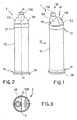
- the delivery device 3 comprises a tank 10, being preferably of a cylindrical shape, which extends along a longitudinal direction defining an X-axis.
- the tank 10 is rigid and hollow, so as to identify a main volume 12 adapted to contain a paste to be delivered, particularly the main component 5 of a multi-mould paste.
- the tank 10 does not have any substantially change in its volume and shape, i.e. it is not deformed by using the deliverer, thus maintaining a cylindrical configuration and its concentricity with the X-axis.
- the tank 10 extends from a first end 16 to a second end 22, which are at opposite ends of the X-axis.
- the tank 10 comprises a support base 28 for the delivery device 3 as well as a thrust unit 34.
- the thrust unit 34 comprises for example a sliding piston 36 inside the tank 10, a flexible ring 38, which is preferably made in aluminium and works as a non-return device, allowing the piston 36 only to move in the direction from the first end 16 to the second end 22 and a hard disk 40 which allows the flexible ring 38 to be held in position by connecting itself to the piston 36.
- the tank 10 provides a coupler portion 42, being substantially of a cylindrical and hollow shape and axially-symmetrical relative to the X-axis of the tank 10, having a diameter which is lower than the diameter of the tank 10.
- the coupler portion 42 comprises on a lateral external surface thereof a couple of circular projections 44 defining or delimiting a notch 45 which is substantially of a toroidal shape.
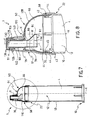
- the tank 10 is associated with a pumping device 46.
- the pumping device 46 comprises operating means 50 and fastening means 51; preferably, said operating means 50 comprise an elastic diaphragm 52 and said fastening means 51 comprise a rigid jig 58.
- the elastic diaphragm 52 comprises a cap portion 64, which is substantially hollow and defines a secondary volume 66 adapted to accommodate a minor component 6 of the multi-component paste, according to an embodiment illustrated for example in figures 9, 10 , 11 and 12 .
- the cap portion 64 is adapted to be fitted onto the coupler portion 42 of the tank 10.
- the cap portion 64 comprises at a lower edge 68 a circular rib 70 adapted to couple with said notch 45 of the coupler portion 42 of the tank 10, so as to allow the cap portion 64 to be fixed on the second end 22 of the tank 10; this fixing is adapted to assure the fluid preservation of the paste contained in the tank 10 and the cap portion 64.
- the elastic diaphragm 52 is associated with an eject pipe 76, i.e. interacts with said eject pipe which is adapted to deliver the multi-component paste.
- the elastic diaphragm 52 is in fluid cooperation with the eject pipe 76, in order to convey the paste through the eject pipe 76.
- the elastic diaphragm 52 comprises the eject pipe 76, for example of a cylindrical shape, passing through the cap portion 64; the cylindrical eject pipe 76 has its own Y-axis which is separate from the X-axis of the tank 10 and parallel to the latter.
- the eject pipe 76 comprises a first portion 78 and a second portion 80, preferably of cylindrical shape and coaxial between themselves and with said Y-axis.
- said Y-axis is a symmetry axis for said eject pipe 76.
- the cap portion 64 and the eject pipe 76 are formed as a single piece.
- the first portion 78 of the eject pipe 76 projects from the cap portion 64 to the lower edge 68 of the cap portion 64, i.e. inside the secondary volume 66 contained in the cap portion 64.
- the second portion 80 projects from the cap portion 64 on the opposite side of the first portion 78, i.e. on the opposite side of the lower edge 68 of the cap portion 64 and the second end 22 of the combined tank 10.
- the first portion 78 of the eject pipe 76 extends within the secondary volume 66.
- the first portion 78 of the eject pipe 76 is provided with an inlet aperture 82 at its end, adapted to convey the paste into the eject pipe 76.
- the inlet aperture 82 of the eject pipe 76, through which the paste flows in order to be dispensed, is not on the X-axis of the tank 10.
- the first portion 78 of the eject pipe 76 is substantially a truncated cone shape, having a diameter increasing towards the inlet aperture 82.
- the inlet aperture 82 is not on axis with the second portion 80 of the eject pipe 76; i.e. the inlet aperture has a W-axis of symetry which is separate from the Y-axis of the second portion 80.
- the inlet aperture 82 is crossed by said Y-axis of the second portion 80 of the eject pipe 76.
- a side edge 84 of the inlet aperture 82 substantially intersects said X-axis of the tank 10, preferably the side edge 84 is tangent to the X-axis.
- the inlet aperture 82 is offset relative to the second portion 80 of the eject pipe 76, said W-axis, relative to a sectional plane crossing the X-axis of the tank 10, being between the X-axis and the Y-axis.
- a hole preferably a plurality of holes 94, passing through the sidewall 88 and adapted to allow said minor component 6 to flow into the eject pipe 76; said minor component 6 being preferably housed inside the secondary volume 66 which is defined by the cap portion 64.
- the minor component 6 is loaded into the cap portion 64 so as to fill the portion of the secondary volume included between a vertex 100 of the cap which is opposite to the lower edge 68 relative to the X-axis, and the inlet aperture 82.
- the second portion 80 of the eject pipe 76 is provided with an eject aperture 106 at one end opposite to the cap portion 64, being adapted to deliver the multi-component paste outside the delivery device 3.
- An operating portion 108 of the cap 64 that is remote from the eject pipe 76 is to be pressed by a user's finger in order to cause the cap portion 64 to be deformed and obtain the delivery of the paste through the eject pipe 76.
- the operating portion 108 of the elastic diaphragm 52 is distanced from the eject pipe 76; in other words, the eject pipe 76 is set in a portion of the elastic diaphragm which is not subjected to the pressure operation from a user.
- the eject pipe 76 and the operating portion 108 are each located in one of said mid-halves.
- the operating portion 108 comprises grip means, such as ribs.
- elastic diaphragm is indicated a diaphragm having such a thickness and material to be deformable when pressed by a user, in order to start the delivery device 3; with the removal of the pressure operation from the user, the elastic diaphragm elastically returns to its shape-retaining cap configuration.
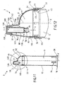
- the rigid jig 58 provides a central body 110 adapted to connect the cap portion 64 of the elastic diaphragm 52 to the tank 10.
- the rigid jig 58 is at least partially counter-shaped relative to the elastic diaphragm 52, so as to limit the deformation thereof and assure the substantial parallelism of the eject pipe 76 while passing from the shape-retaining configuration to the deformed configuration, subsequent to the operating of the elastic diaphragm 52.
- the fastening means 51 assure that the Y-axis of the eject pipe 76 is the same while passing from the shape-retaining configuration to the deformed configuration; in other words, the fastening means assure the substantial immobility of the eject pipe 76 so that the eject pipe 76 is fastened in position while passing from the shape-retaining configuration to the deformed configuration of the elastic diaphragm 52.
- the Y-axis of the eject pipe 76 and the X-axis of the tank 10 are parallel.
- the central body 110 is at least partially counter-shaped relative to said elastic diaphragm 52.
- the central body 110 is provided with a cap shape and is adapted to partially cover the cap portion 64 of the elastic diaphragm 52.
- the rigid jig 58 is at least partially in connection with the elastic diaphragm 52 so as to assure that in the deformed configuration of the elastic diaphragm 52, the latter is not deformed at the contact position with the rigid jig 58.
- the rigid jig is counter-shaped relative to the portion of the elastic diaphragm comprising the eject pipe 76, so that in a deformed configuration of the elastic diaphragm 52, the portion of the elastic diaphragm 52 comprising the eject pipe 76 does not substantially change its shape; in other words, the rigid jig 58 assures the substantial shape-retaining ability of that portion of the elastic diaphragm 52 in direct contact with it.
- the portion of the elastic diaphragm 52 being in direct contact with the rigid jig 58 comprises the eject pipe 76, so as to assure that the eject pipe 76 in the shape-retaining configuration is parallel to the eject pipe 76 in the deformed configuration.
- the central body 110 comprises a fixing portion 114, preferably of a cylindrical shape, adapted to fasten the central body 110 at the second end 22 of the tank 10, so as to block in position the lower edge 68 of the diaphragm 52 in contact with the tank 10.
- the fixing portion 114 covers the coupler portion 42 of the tank 10 thanks to a forced coupling, so as to press the lower edge 68 of the cap portion 64 against said coupler portion 42.
- the fixing portion 114 assures the fixation of the circular projections 44 of the diaphragm in the notch 45 of the tank 10; the lower edge 68 of the cap portion 64 is fixed between the fixing portion 114 and the coupler portion 42.
- the fixing portion 114 contributes to confer rigidity to the lower edge 68 of the diaphragm so as to avoid the possibility of paste passing through the lower edge itself.
- the rigid jig 58 provides a window 118, so that in an assembled configuration of the rigid jig onto the elastic diaphragm, this window overlaps at least partially said operating portion 108 of the cap 64.
- the operating portion 108 of the cap 64 is easy to access by an operator through the window, so as to allow a finger to press it in order to cause the cap to be deformed and obtain the delivery of the paste through the eject pipe.
- the rigid jig 58 comprises a ring 122, being substantially hollow and rigidly connected to the central body 110, and adapted to coupling at least partially with said eject pipe, particularly with the second portion 80 of the eject pipe 76.
- Said ring 122 at one end opposite to the fixing portion 114 comprises a cylindrical length 126 ending with a tip 128 having a hole 130 so that in an assembly configuration of the rigid jig onto the elastic diaphragm, said hole 130 coincides with the eject aperture 106.
- the tip 128 has a circular ring shape so as to form a cut-off for the second portion 80 of the eject pipe 76 towards the Y-axis and in a direction removed from the cap itself.
- the cylindrical length 126 is adapted to accommodate at least partially the second portion of the eject pipe, so as to limit the shifting of the eject pipe to a plane perpendicular to the Y-axis.
- a cap 136 is associated to said ring 122, and it is adapted to close the hole 130 and the eject pipe 106.
- rigid jig is indicated a jig having such a material and configuration that it is not deformed during the dispensing action of the delivery device 3 i.e. while the elastic diaphragm 52 is passing from the shape-retaining configuration to the deformed configuration.
- the function of the rigid jig 58 is to control the deformation of the elastic diaphragm 52 while operating; for example, the ring 122 prevents the eject pipe 76 from moving or inclining so that the Y-axis of the eject pipe is substantially parallel to the X-axis of the tank 10.
- the rigid jig 58 and the elastic diaphragm 52 are enbloc moulded, for example by means of double-moulding techniques.
- the eject pipe is not part of the elastic diaphragm 52, but forms part of the rigid jig 58.
- the elastic diaphragm 52 comprises a housing 138 to which the eject pipe 76 is associated.
- the cylindrical length 126 of the rigid jig 58 is integrally connected with the second portion 80 of the eject pipe 76.
- the eject pipe 76 is connected or cantilevered relative to the rigid jig 58, i.e. the second portion 80 of the eject pipe 76 is rigidly connected to the cylindrical length 126 of the rigid jig 58, whereas the first portion 78 penetrates into the elastic diaphragm 52 through said housing 138, without being connected with the elastic diaphragm 52. Accordingly, the first portion 78 is cantilevered relative to the second portion 80 which is rigidly fastened to the rigid jig 58.
- the ring 122 comprises a stiffening wall 140 which cooperates with the cap 136 and substantially abuts on the vertex 100 of the cap portion 64, so as to limit the deformation of the cap portion along the X-axis.
- said stiffening wall 140 is included between said X-axis and Y-axis.
- the cap 136 is opened, then the operator presses the elastic diaphragm 52 with one finger in the direction of the thrust unit 34.
- the piston 36 of the thrust unit 34 is supported by the flexible ring 38, thus it can not move to the first end 16 of the tank 10 along the X-axis.
- the paste contained in the tank 10 is pressurised and obliged to flow through the first portion 78 of the eject pipe 76.
- the volume of the paste ejected is substantially equal to the volume obtained by deforming the cap portion 64, i.e. the difference between the volumes of the shape-retaining cap portion 64 and the deformed cap portion 64.
- the minor component 6 flows through the holes 94 of the eject pipe 76 combining with the main component 5 which is conveyed through the inlet aperture 82 to the eject pipe 76.
- the paste is conveyed to the inlet aperture 82 of the eject pipe 76.
- This under-pressure has the effect of pushing the piston 36 towards the second end 22 of the tank 10, causing the feed of the piston itself.
- said under-pressure being generated inside the delivery device has the effect of drawing in an amount of air through the eject aperture 106 so as to push an amount of paste that is in the eject pipe towards the inlet aperture 82 of the pipe itself.
- the length and section of the eject pipe are set up by physical and geometrical parameters of the paste and the tank, as known in the art, so as to assure that the eject pipe is never completely empty, thus preventing that the air may enter the tank.
- the feed of the piston assures that the outlet length, i.e. the second portion 80 of the eject pipe 76 is always filled at the end of each paste pumping, so as to avoid the forming of a vortex which would compromise the visual aspect as well as the paste composition.
- the eject pipe Before first use of the delivery device, the eject pipe is at least partially filled with paste, so that when the elastic diaphragm is first put into operation, the paste completely fills up the eject pipe, thus preventing that the air may enter during the following intake or under-pressure step.
- fastening means 51 particularly of the rigid jig 58 assures that the eject pipe 76 in its shape-retaining condition is parallel to the eject pipe 76 in its deformed configuration.
- the delivery device 3 according to the invention allows drawbacks that may exist in the delivery devices of the prior art to be overcome.
- the described delivery device allows a multi-component type paste to be delivered by assuring the composition and the desired aesthetical aspect thereof.
- the main component is contained in the tank and the minor component in the cap portion.
- the piston pushes the main component into the eject pipe and the elastic diaphragm directly conveys the minor component to the same duct, so as to provide a multi-component paste having for example, a form consisting of the main component and a certain number of stripes, equal to the number of holes that are on the sidewall of the eject pipe, being composed by the minor component and equally spaced around the main component.
- the fastening means of the eject pipe assures the fixing in position of the eject pipe and the desired aesthetical aspect for the delivered paste.
- the various components are contained in the tank, comprising for example a central pipe containing the main component and a lateral tube nest containing the various minor components.
- the piston pushes the various bodies in the eject pipe so as to provide the desired multi-component configuration; following the operation of the elastic diaphragm, the parallelism of the eject pipe assures the preservation of the paste thus combined in the duct itself.
- the parallelism of the eject pipe with the X-axis of the tank, while passing from the shape-retaining configuration to the deformed configuration and vice versa assures that the main component is properly combined with the minor components, thus avoiding the forming of a vortex inside the paste, which would compromise the aesthetical aspect of and the composition of the delivered paste.
- the delivery device is cost-effective in production and assembly.
Landscapes
- Engineering & Computer Science (AREA)
- Mechanical Engineering (AREA)
- Closures For Containers (AREA)
- Reciprocating Pumps (AREA)
- Feeding, Discharge, Calcimining, Fusing, And Gas-Generation Devices (AREA)
- Containers And Packaging Bodies Having A Special Means To Remove Contents (AREA)
- Confectionery (AREA)
- Coating Apparatus (AREA)
Claims (37)
- Abgabe- bzw. Liefervorrichtung (3), die angepasst ist, eine Paste des Multikomponententyps abzugeben bzw. zu liefern, die wenigstens zwei Komponenten (5, 6) umfasst, wobei die Vorrichtung umfasst- einen starren Tank (10), der wenigstens eine der Komponenten (5, 6) enthält,- ein Ausstoßrohr (76) in Fluidkommunikation bzw. -verbindung mit dem Tank (10), um die Paste abzugeben,- eine elastische Membran (52), die dem Tank (10) zugeordnet ist, wobei die elastische Membran (52) einen verformbaren Bedienabschnitt (108) umfasst, der von einer Bedienperson zu drücken ist, um aus einer Formbeibehaltungskonfiguration in eine verformte Konfiguration überzugehen, um die Paste durch das Ausstoßrohr (76) zu pumpen,- Befestigungsmittel (51) für das Ausstoßrohr (76), um das Ausstoßrohr so zu befestigen, dass das Ausstoßrohr (76) in der Formbeibehaltungskonfiguration der elastischen Membran (52) im Wesentlichen parallel zu dem Ausstoßrohr (76) in der verformten Konfiguration der elastischen Membran (52) ist,dadurch gekennzeichnet, dass
die Befestigungsmittel (51) eine starre Einrichtung (58) umfassen, die zumindest teilweise gegensätzlich relativ zu der elastischen Membran (52) geformt ist, um so die Verformung der elastischen Membran (52) während des Übergangs aus der Formbeibehaltungskonfiguration in die verformte Konfiguration zu begrenzen. - Abgabevorrichtung (3) nach Anspruch 1, wobei die elastische Membran (52) einen Kappenabschnitt (64) umfasst, der angepasst ist, auf einen Koppelabschnitt (42) des Tanks (10) gepasst zu sein, wobei der Kappenabschnitt (64) im Wesentlichen hohl ist, um ein sekundäres Volumen (66) bzw. Raum zu definieren, das bzw. der wenigstens eine Komponente (5, 6) der Multiformpaste (4) aufnimmt.
- Abgabevorrichtung (3) nach Anspruch 2, wobei das Ausstoßrohr (76) durch den Kappenabschnitt (64) verläuft.
- Abgabevorrichtung (3) nach Anspruch 2 oder 3, wobei der Kappenabschnitt (64) eine kreisförmige Rippe (70) umfasst, die angepasst ist, mit einer Kerbe (45) des Koppelabschnitts (42) des Tanks (10) zu koppeln, um zu erlauben, dass der Kappenabschnitt (64) an dem Tank (10) befestigt wird.
- Abgabevorrichtung (3) nach einem der vorhergehenden Ansprüche, wobei das Ausstoßrohr (76) in einer im Wesentlichen zylindrischen Form um eine Achse (Y) ist, die im Wesentlichen parallel zu einer Längsachse (X) des Tanks (10) ist.
- Abgabevorrichtung (3) nach einem der Ansprüche 2 bis 5, wobei das Ausstoßrohr (76) einen ersten Abschnitt (78), der von dem Kappenabschnitt (64) zu einer unteren Kante bzw. Rand (68) des Kappenabschnitts (64) vorsteht, und einen zweiten Abschnitt (80) umfasst, der von dem Kappenabschnitt (64) an der entgegengesetzten bzw. gegenüberliegenden Seite relativ zu dem ersten Abschnitt (78) vorsteht.
- Abgabevorrichtung (3) nach Anspruch 6, wobei der erste Abschnitt (78) des Ausstoßrohrs (76) an dem Ende mit einer Einlassöffnung (82) versehen ist, um die Paste in das Ausstoßrohr (76) zu befördern, und der zweite Abschnitt (80) mit einer Ausstoßöffnung (106) versehen ist, um die Paste abzugeben.
- Abgabevorrichtung (3) nach Anspruch 6 oder 7, wobei der erste und der zweite Abschnitt (78, 80) einstückig gebildet sind.
- Abgabevorrichtung (3) nach einem der Ansprüche 6 bis 8, wobei der erste und der zweite Abschnitt (78, 80) zylindrisch und koaxial relativ zu der Achse (Y) sind.
- Abgabevorrichtung (3) nach einem der Ansprüche 7 bis 9, wobei die Einlassöffnung (82) koaxial mit bzw. zu der Achse (Y) und getrennt von der Achse (X) des Tanks (10) ist.
- Abgabevorrichtung (3) nach einem der Ansprüche 7 bis 10, wobei die Einlassöffnung (82) und die Ausstoßöffnung (106) koaxial sind.
- Abgabevorrichtung (3) nach einem der Ansprüche 6 bis 11, wobei der erste Abschnitt (78) des Ausstoßrohrs (76) im Wesentlichen ein Kegelstumpf mit einem Durchmesser ist, der sich in einer Richtung weg von dem zweiten Abschnitt (80) vergrößert.
- Abgabevorrichtung (3) nach Anspruch 12, wobei die Einlassöffnung (82) symmetrisch um eine Achse (W) ist, die von der Achse (Y) des zweiten Abschnitts (80) getrennt ist.
- Abgabevorrichtung (3) nach einem der Ansprüche 7 bis 13, wobei die Einlassöffnung (82) von der Achse (Y) des zweiten Abschnitts (80) des Ausstoßrohrs (76) gekreuzt wird.
- Abgabevorrichtung (3) nach einem der Ansprüche 6 bis 14, wobei an einer Seitenwand (88) des zweiten Abschnitts (80) wenigstens ein Loch (94) vorgesehen ist, das durch die Seitenwand (88) verläuft, um der kleineren Komponente (6) zu erlauben, in das Ausstoßrohr (76) zu fließen.
- Abgabevorrichtung (3) nach einem der Ansprüche 2 bis 15, wobei wenigstens eine kleinere Komponente (6) in den Kappenabschnitt (64) geladen ist bzw. wird, um einen Teil des sekundären Volumens bzw. Raums (66) zu füllen, das bzw. der zwischen einem Scheitelpunkt (100) des Kappenabschnitts (64) entgegengesetzt bzw. gegenüberliegend der unteren Kante bzw. Rand (68) relativ zu der Achse (X) und der Einlassöffnung (82) des Ausstoßrohrs (76) enthalten ist.
- Abgabevorrichtung (3) nach einem der Ansprüche 2 bis 16, wobei der Kappenabschnitt (64) einen Bedienabschnitt (108) entfernt von dem Ausstoßrohr (76) umfasst, der von dem Finger einer Bedienperson zu drücken ist, um zu erlauben, dass der Kappenabschnitt (64) verformt wird.
- Abgabevorrichtung (3) nach Anspruch 17, wobei der Bedienabschnitt (108) Greifmittel umfasst.
- Abgabevorrichtung (3) nach einem der vorhergehenden Ansprüche, wobei die elastische Membran (52) und das Ausstoßrohr (76) als ein einzelnes Stück gebildet sind.
- Abgabevorrichtung (3) nach einem der Ansprüche 2 bis 19, wobei die starre Einrichtung (58) einen zentralen Körper (110) umfasst, der zumindest teilweise gegensätzlich relativ zu dem Kappenabschnitt (64) der elastischen Membran (52) geformt ist.
- Abgabevorrichtung (3) nach Anspruch 20, wobei der zentrale Körper (110) einen Fixierabschnitt (114) umfasst, um die starre Einrichtung (58) an dem Tank (10) zu befestigen, um die untere Kante bzw. Rand (68) der elastischen Membran (52) in Kontakt mit dem Tank (10) zu fixieren.
- Abgabevorrichtung (3) nach Anspruch 20 oder 21, wobei der zentrale Körper (110) ein Fenster (118) umfasst, so dass das Fenster (118) in einer zusammengesetzten Konfiguration der starren Einrichtung (58) auf der elastischen Membran (52) den Bedienabschnitt (108) der Kappe (64) teilweise überlappt, was einer Bedienperson einen Zugang zu dem Bedienabschnitt (108) erlaubt.
- Abgabevorrichtung (3) nach einem der Ansprüche 20 bis 22, wobei die starre Einrichtung (58) einen Ring (122) umfasst, der starr mit dem zentralen Körper (110) verbunden ist, um mit dem zweiten Abschnitt (80) des Ausstoßrohrs (76) zu koppeln.
- Abgabevorrichtung (3) nach Anspruch 23, wobei der Ring (122) an dem Ende entgegengesetzt bzw. gegenüberliegend des Fixierabschnitts (114) eine Zylinderlänge (126) umfasst, die eine Spitze (128) mit einem Loch (130) aufweist, das im Wesentlichen koaxial mit bzw. zu der Achse (Y) ist, so dass das Loch (130) in einer zusammengesetzten Konfiguration der starren Einrichtung (58) auf der elastischen Membran (52) im Wesentlichen mit der Ausstoßöffnung (106) übereinstimmt bzw. -fällt.
- Abgabevorrichtung (3) nach Anspruch 24, wobei die Spitze (128), die eine kreisförmige Ringform aufweist, einen Ausschnitt für den zweiten Abschnitt (80) des Ausstoßrohrs (76) zu der Achse (Y) hin und in einer Richtung entfernt von dem Kappenabschnitt (64) bildet.
- Abgabevorrichtung (3) nach Anspruch 24 oder 25, wobei die Zylinderlänge (126) angepasst ist, den zweiten Abschnitt (80) des Ausstoßrohrs (76) gemäß einer forcierten Kopplung wenigstens teilweise aufzunehmen, um die Verschiebung bzw. das Gleiten des Ausstoßrohrs (76) zu einer Ebene senkrecht zu der Achse (Y) einzugrenzen.
- Abgabevorrichtung (3) nach einem der Ansprüche 23 bis 26, wobei eine Kappe (136) dem Ring (122) zugeordnet ist und angepasst ist, das Loch (130) der Spitze (128) zu schließen.
- Abgabevorrichtung (3) nach einem der Ansprüche 20 bis 27, wobei die starre Einrichtung (58) das Ausstoßrohr (76) umfasst.
- Abgabevorrichtung (3) nach Anspruch 28, wobei die starre Einrichtung (58) integral bzw. einstückig mit dem zweiten Abschnitt (80) des Ausstoßrohrs (76) verbunden ist.
- Abgabevorrichtung (3) nach Anspruch 28 oder 29, wobei die starre Einrichtung (58) und der zweite Abschnitt (80) des Ausstoßrohrs (76) als ein einzelnes Stück gebildet sind.
- Abgabevorrichtung (3) nach einem der Ansprüche 28 bis 30, wobei die elastische Membran (52) ein Gehäuse (138) umfasst, dem das Ausstoßrohr (76) zugeordnet ist.
- Abgabevorrichtung (3) nach einem der Ansprüche 28 bis 31, wobei das Ausstoßrohr (76) freitragend relativ zu der starren Einrichtung (58) ist.
- Abgabevorrichtung (3) nach Anspruch 32, wobei der zweite Abschnitt (80) des Ausstoßrohrs (76) starr mit der Zylinderlänge (126) verbunden ist und der erste Abschnitt (78) in die elastische Membran (52) penetriert, um freitragend relativ zu dem zweiten Abschnitt (80) zu sein.
- Abgabevorrichtung (3) nach einem der Ansprüche 28 bis 33, wobei die starre Einrichtung (58) und die elastische Membran (52) en bloc mittels Doppelguß geformt bzw. gegossen sind.
- Abgabevorrichtung (3) nach einem der Ansprüche 23 bis 34, wobei der Ring (122) eine Versteifungswand (140) umfasst, die an den Scheitelpunkt (100) des Kappenabschnitts (64) anschlägt bzw. anliegt, um die Verformung des Kappenabschnitts (64) entlang der Längsachse (X) einzuschränken.
- Abgabevorrichtung (3) nach Anspruch 35, wobei die Versteifungswand (140) zwischen den Achsen (X) und (Y) angeordnet ist.
- Abgabevorrichtung (3) nach einem der vorhergehenden Ansprüche, wobei die Achse (Y) des Ausstoßrohrs (76) in der Formbeibehaltungskonfiguration der elastischen Membran (52) mit der Achse (Y) des Ausstoßrohrs (76) in der verformten Konfiguration der elastischen Membran (52) übereinstimmt bzw. -fällt.
Applications Claiming Priority (2)
| Application Number | Priority Date | Filing Date | Title |
|---|---|---|---|
| IT002261A ITMI20032261A1 (it) | 2003-11-20 | 2003-11-20 | Dispositivo erogatore |
| ITMI20032261 | 2003-11-20 |
Publications (3)
| Publication Number | Publication Date |
|---|---|
| EP1533247A2 EP1533247A2 (de) | 2005-05-25 |
| EP1533247A3 EP1533247A3 (de) | 2005-10-12 |
| EP1533247B1 true EP1533247B1 (de) | 2008-10-22 |
Family
ID=34430773
Family Applications (1)
| Application Number | Title | Priority Date | Filing Date |
|---|---|---|---|
| EP04024464A Expired - Lifetime EP1533247B1 (de) | 2003-11-20 | 2004-10-14 | Pumpbetägigbarer Spender |
Country Status (4)
| Country | Link |
|---|---|
| EP (1) | EP1533247B1 (de) |
| AT (1) | ATE411952T1 (de) |
| DE (1) | DE602004017267D1 (de) |
| IT (1) | ITMI20032261A1 (de) |
Families Citing this family (2)
| Publication number | Priority date | Publication date | Assignee | Title |
|---|---|---|---|---|
| DE102011102524A1 (de) * | 2011-05-26 | 2012-11-29 | Krallmann Kunststoffverarbeitung Gmbh | Spender |
| CN108249025A (zh) * | 2017-12-14 | 2018-07-06 | 宁波圣捷喷雾泵有限公司 | 一种胶体包装结构 |
Family Cites Families (2)
| Publication number | Priority date | Publication date | Assignee | Title |
|---|---|---|---|---|
| FR2594419B1 (fr) * | 1986-02-14 | 1988-12-02 | Aerosol Inventions Dev | Procede pour distribuer une substance visqueuse par doses successives et conditionnement pour sa mise en oeuvre |
| GR880100328A (el) * | 1987-05-20 | 1989-02-23 | Colgate Palmolive Co | Διανομευς δια την κατα δοσεις διανομην υλικων μορφης παστης. |
-
2003
- 2003-11-20 IT IT002261A patent/ITMI20032261A1/it unknown
-
2004
- 2004-10-14 DE DE602004017267T patent/DE602004017267D1/de not_active Expired - Fee Related
- 2004-10-14 EP EP04024464A patent/EP1533247B1/de not_active Expired - Lifetime
- 2004-10-14 AT AT04024464T patent/ATE411952T1/de not_active IP Right Cessation
Also Published As
| Publication number | Publication date |
|---|---|
| ATE411952T1 (de) | 2008-11-15 |
| ITMI20032261A1 (it) | 2005-05-21 |
| EP1533247A3 (de) | 2005-10-12 |
| EP1533247A2 (de) | 2005-05-25 |
| DE602004017267D1 (de) | 2008-12-04 |
Similar Documents
| Publication | Publication Date | Title |
|---|---|---|
| EP1886736B1 (de) | Pumpe für Flüssigkeitsspender | |
| HU221949B1 (hu) | Billentyűs-szivattyús folyadékadagoló | |
| US5014881A (en) | Metering and spray pump for liquid and low-viscosity substances | |
| US4142651A (en) | Fluid dispenser with flexible outlet tube and pinching valve | |
| EP2371252B1 (de) | Pumpe mit stationärem Schaft | |
| EP1667801B1 (de) | Abgabevorrichtung | |
| JPH02180178A (ja) | ペーストスペンダ | |
| US20050035157A1 (en) | Pump for dispensing flowable material | |
| JP6633546B2 (ja) | 流体製品投与及び塗布用の組立体 | |
| US20070041779A1 (en) | Manual and electrical pump toothbrushes for dispensing liquid and paste dentifrices | |
| CN114162452B (zh) | 用于喷射液体的容器 | |
| US5813573A (en) | Dispenser for the simultaneous delivery of at least two paste-like products | |
| JP7092804B2 (ja) | 改善されたトリガ機能を備えた製品を分注するための装置 | |
| PL200833B1 (pl) | Dozownik z pojemnikiem aplikowanego środka oraz pompka do dozownika | |
| WO2015097606A2 (en) | Product container suited to be associated with a dispensing device suited to dispense said product and related dispensing system | |
| US5356049A (en) | Hand pump assembly with a pump mechanism which is independent of the pump housing | |
| HUP0302510A2 (hu) | Továbbfejlesztett szeleppel ellátott pumpás adagoló | |
| JP2006306501A (ja) | ポンプディスペンサ及びそのバルブアセンブリ | |
| US6334552B1 (en) | Dispenser with peripheral delivery mode | |
| CN116323405B (zh) | 用于喷射液体的容器 | |
| EP1533247B1 (de) | Pumpbetägigbarer Spender | |
| EP2121462B1 (de) | Einlass für eine pumpe | |
| US6742677B2 (en) | Fluid dispenser pump | |
| JP2006505463A (ja) | 流動性または半流動性製品の保管兼放出装置 | |
| CN116096644B (zh) | 用于喷射液体的容器 |
Legal Events
| Date | Code | Title | Description |
|---|---|---|---|
| PUAI | Public reference made under article 153(3) epc to a published international application that has entered the european phase |
Free format text: ORIGINAL CODE: 0009012 |
|
| AK | Designated contracting states |
Kind code of ref document: A2 Designated state(s): AT BE BG CH CY CZ DE DK EE ES FI FR GB GR HU IE IT LI LU MC NL PL PT RO SE SI SK TR |
|
| AX | Request for extension of the european patent |
Extension state: AL HR LT LV MK |
|
| PUAL | Search report despatched |
Free format text: ORIGINAL CODE: 0009013 |
|
| AK | Designated contracting states |
Kind code of ref document: A3 Designated state(s): AT BE BG CH CY CZ DE DK EE ES FI FR GB GR HU IE IT LI LU MC NL PL PT RO SE SI SK TR |
|
| AX | Request for extension of the european patent |
Extension state: AL HR LT LV MK |
|
| RIC1 | Information provided on ipc code assigned before grant |
Ipc: 7B 65D 83/00 A Ipc: 7B 65D 47/20 B |
|
| 17P | Request for examination filed |
Effective date: 20050926 |
|
| AKX | Designation fees paid |
Designated state(s): AT BE BG CH CY CZ DE DK EE ES FI FR GB GR HU IE IT LI LU MC NL PL PT RO SE SI SK TR |
|
| 17Q | First examination report despatched |
Effective date: 20070423 |
|
| GRAP | Despatch of communication of intention to grant a patent |
Free format text: ORIGINAL CODE: EPIDOSNIGR1 |
|
| GRAS | Grant fee paid |
Free format text: ORIGINAL CODE: EPIDOSNIGR3 |
|
| GRAA | (expected) grant |
Free format text: ORIGINAL CODE: 0009210 |
|
| AK | Designated contracting states |
Kind code of ref document: B1 Designated state(s): AT BE BG CH CY CZ DE DK EE ES FI FR GB GR HU IE IT LI LU MC NL PL PT RO SE SI SK TR |
|
| REG | Reference to a national code |
Ref country code: GB Ref legal event code: FG4D |
|
| REG | Reference to a national code |
Ref country code: CH Ref legal event code: EP |
|
| REG | Reference to a national code |
Ref country code: IE Ref legal event code: FG4D |
|
| REF | Corresponds to: |
Ref document number: 602004017267 Country of ref document: DE Date of ref document: 20081204 Kind code of ref document: P |
|
| NLV1 | Nl: lapsed or annulled due to failure to fulfill the requirements of art. 29p and 29m of the patents act | ||
| PG25 | Lapsed in a contracting state [announced via postgrant information from national office to epo] |
Ref country code: BG Free format text: LAPSE BECAUSE OF FAILURE TO SUBMIT A TRANSLATION OF THE DESCRIPTION OR TO PAY THE FEE WITHIN THE PRESCRIBED TIME-LIMIT Effective date: 20090122 Ref country code: AT Free format text: LAPSE BECAUSE OF FAILURE TO SUBMIT A TRANSLATION OF THE DESCRIPTION OR TO PAY THE FEE WITHIN THE PRESCRIBED TIME-LIMIT Effective date: 20081022 Ref country code: ES Free format text: LAPSE BECAUSE OF FAILURE TO SUBMIT A TRANSLATION OF THE DESCRIPTION OR TO PAY THE FEE WITHIN THE PRESCRIBED TIME-LIMIT Effective date: 20090202 |
|
| PG25 | Lapsed in a contracting state [announced via postgrant information from national office to epo] |
Ref country code: SI Free format text: LAPSE BECAUSE OF FAILURE TO SUBMIT A TRANSLATION OF THE DESCRIPTION OR TO PAY THE FEE WITHIN THE PRESCRIBED TIME-LIMIT Effective date: 20081022 Ref country code: PT Free format text: LAPSE BECAUSE OF FAILURE TO SUBMIT A TRANSLATION OF THE DESCRIPTION OR TO PAY THE FEE WITHIN THE PRESCRIBED TIME-LIMIT Effective date: 20090323 Ref country code: NL Free format text: LAPSE BECAUSE OF FAILURE TO SUBMIT A TRANSLATION OF THE DESCRIPTION OR TO PAY THE FEE WITHIN THE PRESCRIBED TIME-LIMIT Effective date: 20081022 Ref country code: PL Free format text: LAPSE BECAUSE OF FAILURE TO SUBMIT A TRANSLATION OF THE DESCRIPTION OR TO PAY THE FEE WITHIN THE PRESCRIBED TIME-LIMIT Effective date: 20081022 Ref country code: FI Free format text: LAPSE BECAUSE OF FAILURE TO SUBMIT A TRANSLATION OF THE DESCRIPTION OR TO PAY THE FEE WITHIN THE PRESCRIBED TIME-LIMIT Effective date: 20081022 |
|
| PG25 | Lapsed in a contracting state [announced via postgrant information from national office to epo] |
Ref country code: RO Free format text: LAPSE BECAUSE OF FAILURE TO SUBMIT A TRANSLATION OF THE DESCRIPTION OR TO PAY THE FEE WITHIN THE PRESCRIBED TIME-LIMIT Effective date: 20081022 Ref country code: EE Free format text: LAPSE BECAUSE OF FAILURE TO SUBMIT A TRANSLATION OF THE DESCRIPTION OR TO PAY THE FEE WITHIN THE PRESCRIBED TIME-LIMIT Effective date: 20081022 Ref country code: BE Free format text: LAPSE BECAUSE OF FAILURE TO SUBMIT A TRANSLATION OF THE DESCRIPTION OR TO PAY THE FEE WITHIN THE PRESCRIBED TIME-LIMIT Effective date: 20081022 Ref country code: DK Free format text: LAPSE BECAUSE OF FAILURE TO SUBMIT A TRANSLATION OF THE DESCRIPTION OR TO PAY THE FEE WITHIN THE PRESCRIBED TIME-LIMIT Effective date: 20081022 |
|
| PLBE | No opposition filed within time limit |
Free format text: ORIGINAL CODE: 0009261 |
|
| STAA | Information on the status of an ep patent application or granted ep patent |
Free format text: STATUS: NO OPPOSITION FILED WITHIN TIME LIMIT |
|
| PG25 | Lapsed in a contracting state [announced via postgrant information from national office to epo] |
Ref country code: CZ Free format text: LAPSE BECAUSE OF FAILURE TO SUBMIT A TRANSLATION OF THE DESCRIPTION OR TO PAY THE FEE WITHIN THE PRESCRIBED TIME-LIMIT Effective date: 20081022 Ref country code: SE Free format text: LAPSE BECAUSE OF FAILURE TO SUBMIT A TRANSLATION OF THE DESCRIPTION OR TO PAY THE FEE WITHIN THE PRESCRIBED TIME-LIMIT Effective date: 20090122 |
|
| 26N | No opposition filed |
Effective date: 20090723 |
|
| PG25 | Lapsed in a contracting state [announced via postgrant information from national office to epo] |
Ref country code: SK Free format text: LAPSE BECAUSE OF FAILURE TO SUBMIT A TRANSLATION OF THE DESCRIPTION OR TO PAY THE FEE WITHIN THE PRESCRIBED TIME-LIMIT Effective date: 20081022 |
|
| PG25 | Lapsed in a contracting state [announced via postgrant information from national office to epo] |
Ref country code: MC Free format text: LAPSE BECAUSE OF NON-PAYMENT OF DUE FEES Effective date: 20091031 |
|
| REG | Reference to a national code |
Ref country code: CH Ref legal event code: PL |
|
| REG | Reference to a national code |
Ref country code: IE Ref legal event code: MM4A |
|
| PG25 | Lapsed in a contracting state [announced via postgrant information from national office to epo] |
Ref country code: DE Free format text: LAPSE BECAUSE OF NON-PAYMENT OF DUE FEES Effective date: 20100501 |
|
| PG25 | Lapsed in a contracting state [announced via postgrant information from national office to epo] |
Ref country code: CH Free format text: LAPSE BECAUSE OF NON-PAYMENT OF DUE FEES Effective date: 20091031 Ref country code: GR Free format text: LAPSE BECAUSE OF FAILURE TO SUBMIT A TRANSLATION OF THE DESCRIPTION OR TO PAY THE FEE WITHIN THE PRESCRIBED TIME-LIMIT Effective date: 20090123 Ref country code: LI Free format text: LAPSE BECAUSE OF NON-PAYMENT OF DUE FEES Effective date: 20091031 Ref country code: IE Free format text: LAPSE BECAUSE OF NON-PAYMENT OF DUE FEES Effective date: 20091014 |
|
| PG25 | Lapsed in a contracting state [announced via postgrant information from national office to epo] |
Ref country code: LU Free format text: LAPSE BECAUSE OF NON-PAYMENT OF DUE FEES Effective date: 20091014 |
|
| PG25 | Lapsed in a contracting state [announced via postgrant information from national office to epo] |
Ref country code: HU Free format text: LAPSE BECAUSE OF FAILURE TO SUBMIT A TRANSLATION OF THE DESCRIPTION OR TO PAY THE FEE WITHIN THE PRESCRIBED TIME-LIMIT Effective date: 20090423 |
|
| PG25 | Lapsed in a contracting state [announced via postgrant information from national office to epo] |
Ref country code: TR Free format text: LAPSE BECAUSE OF FAILURE TO SUBMIT A TRANSLATION OF THE DESCRIPTION OR TO PAY THE FEE WITHIN THE PRESCRIBED TIME-LIMIT Effective date: 20081022 |
|
| PG25 | Lapsed in a contracting state [announced via postgrant information from national office to epo] |
Ref country code: CY Free format text: LAPSE BECAUSE OF FAILURE TO SUBMIT A TRANSLATION OF THE DESCRIPTION OR TO PAY THE FEE WITHIN THE PRESCRIBED TIME-LIMIT Effective date: 20081022 |
|
| PGFP | Annual fee paid to national office [announced via postgrant information from national office to epo] |
Ref country code: FR Payment date: 20121205 Year of fee payment: 9 |
|
| PGFP | Annual fee paid to national office [announced via postgrant information from national office to epo] |
Ref country code: GB Payment date: 20121019 Year of fee payment: 9 |
|
| GBPC | Gb: european patent ceased through non-payment of renewal fee |
Effective date: 20131014 |
|
| PG25 | Lapsed in a contracting state [announced via postgrant information from national office to epo] |
Ref country code: GB Free format text: LAPSE BECAUSE OF NON-PAYMENT OF DUE FEES Effective date: 20131014 |
|
| REG | Reference to a national code |
Ref country code: FR Ref legal event code: ST Effective date: 20140630 |
|
| PG25 | Lapsed in a contracting state [announced via postgrant information from national office to epo] |
Ref country code: FR Free format text: LAPSE BECAUSE OF NON-PAYMENT OF DUE FEES Effective date: 20131031 |
|
| P01 | Opt-out of the competence of the unified patent court (upc) registered |
Effective date: 20230523 |
|
| PGFP | Annual fee paid to national office [announced via postgrant information from national office to epo] |
Ref country code: IT Payment date: 20230807 Year of fee payment: 20 |