EP1533177B1 - Retractable seats - Google Patents
Retractable seats Download PDFInfo
- Publication number
- EP1533177B1 EP1533177B1 EP04257090A EP04257090A EP1533177B1 EP 1533177 B1 EP1533177 B1 EP 1533177B1 EP 04257090 A EP04257090 A EP 04257090A EP 04257090 A EP04257090 A EP 04257090A EP 1533177 B1 EP1533177 B1 EP 1533177B1
- Authority
- EP
- European Patent Office
- Prior art keywords
- seat
- support member
- cushion
- seat back
- framework
- Prior art date
- Legal status (The legal status is an assumption and is not a legal conclusion. Google has not performed a legal analysis and makes no representation as to the accuracy of the status listed.)
- Expired - Fee Related
Links
Images


Classifications
-
- B—PERFORMING OPERATIONS; TRANSPORTING
- B60—VEHICLES IN GENERAL
- B60N—SEATS SPECIALLY ADAPTED FOR VEHICLES; VEHICLE PASSENGER ACCOMMODATION NOT OTHERWISE PROVIDED FOR
- B60N2/00—Seats specially adapted for vehicles; Arrangement or mounting of seats in vehicles
- B60N2/24—Seats specially adapted for vehicles; Arrangement or mounting of seats in vehicles for particular purposes or particular vehicles
- B60N2/30—Non-dismountable or dismountable seats storable in a non-use position, e.g. foldable spare seats
- B60N2/3038—Cushion movements
- B60N2/3063—Cushion movements by composed movement
- B60N2/3065—Cushion movements by composed movement in a longitudinal-vertical plane
-
- B—PERFORMING OPERATIONS; TRANSPORTING
- B60—VEHICLES IN GENERAL
- B60N—SEATS SPECIALLY ADAPTED FOR VEHICLES; VEHICLE PASSENGER ACCOMMODATION NOT OTHERWISE PROVIDED FOR
- B60N2/00—Seats specially adapted for vehicles; Arrangement or mounting of seats in vehicles
- B60N2/24—Seats specially adapted for vehicles; Arrangement or mounting of seats in vehicles for particular purposes or particular vehicles
- B60N2/30—Non-dismountable or dismountable seats storable in a non-use position, e.g. foldable spare seats
- B60N2/3002—Non-dismountable or dismountable seats storable in a non-use position, e.g. foldable spare seats back-rest movements
- B60N2/3004—Non-dismountable or dismountable seats storable in a non-use position, e.g. foldable spare seats back-rest movements by rotation only
- B60N2/3009—Non-dismountable or dismountable seats storable in a non-use position, e.g. foldable spare seats back-rest movements by rotation only about transversal axis
- B60N2/3011—Non-dismountable or dismountable seats storable in a non-use position, e.g. foldable spare seats back-rest movements by rotation only about transversal axis the back-rest being hinged on the cushion, e.g. "portefeuille movement"
-
- B—PERFORMING OPERATIONS; TRANSPORTING
- B60—VEHICLES IN GENERAL
- B60N—SEATS SPECIALLY ADAPTED FOR VEHICLES; VEHICLE PASSENGER ACCOMMODATION NOT OTHERWISE PROVIDED FOR
- B60N2/00—Seats specially adapted for vehicles; Arrangement or mounting of seats in vehicles
- B60N2/24—Seats specially adapted for vehicles; Arrangement or mounting of seats in vehicles for particular purposes or particular vehicles
- B60N2/30—Non-dismountable or dismountable seats storable in a non-use position, e.g. foldable spare seats
- B60N2/3072—Non-dismountable or dismountable seats storable in a non-use position, e.g. foldable spare seats on a lower level of a multi-level vehicle floor
-
- B—PERFORMING OPERATIONS; TRANSPORTING
- B60—VEHICLES IN GENERAL
- B60N—SEATS SPECIALLY ADAPTED FOR VEHICLES; VEHICLE PASSENGER ACCOMMODATION NOT OTHERWISE PROVIDED FOR
- B60N2/00—Seats specially adapted for vehicles; Arrangement or mounting of seats in vehicles
- B60N2/24—Seats specially adapted for vehicles; Arrangement or mounting of seats in vehicles for particular purposes or particular vehicles
- B60N2/30—Non-dismountable or dismountable seats storable in a non-use position, e.g. foldable spare seats
- B60N2/3088—Non-dismountable or dismountable seats storable in a non-use position, e.g. foldable spare seats characterised by the mechanical link
- B60N2/309—Non-dismountable or dismountable seats storable in a non-use position, e.g. foldable spare seats characterised by the mechanical link rods
-
- B—PERFORMING OPERATIONS; TRANSPORTING
- B60—VEHICLES IN GENERAL
- B60N—SEATS SPECIALLY ADAPTED FOR VEHICLES; VEHICLE PASSENGER ACCOMMODATION NOT OTHERWISE PROVIDED FOR
- B60N2/00—Seats specially adapted for vehicles; Arrangement or mounting of seats in vehicles
- B60N2/24—Seats specially adapted for vehicles; Arrangement or mounting of seats in vehicles for particular purposes or particular vehicles
- B60N2/32—Seats specially adapted for vehicles; Arrangement or mounting of seats in vehicles for particular purposes or particular vehicles convertible for other use
- B60N2/36—Seats specially adapted for vehicles; Arrangement or mounting of seats in vehicles for particular purposes or particular vehicles convertible for other use into a loading platform
-
- B—PERFORMING OPERATIONS; TRANSPORTING
- B60—VEHICLES IN GENERAL
- B60N—SEATS SPECIALLY ADAPTED FOR VEHICLES; VEHICLE PASSENGER ACCOMMODATION NOT OTHERWISE PROVIDED FOR
- B60N2/00—Seats specially adapted for vehicles; Arrangement or mounting of seats in vehicles
- B60N2/70—Upholstery springs ; Upholstery
- B60N2/72—Attachment or adjustment thereof
-
- B—PERFORMING OPERATIONS; TRANSPORTING
- B60—VEHICLES IN GENERAL
- B60N—SEATS SPECIALLY ADAPTED FOR VEHICLES; VEHICLE PASSENGER ACCOMMODATION NOT OTHERWISE PROVIDED FOR
- B60N2/00—Seats specially adapted for vehicles; Arrangement or mounting of seats in vehicles
- B60N2/80—Head-rests
- B60N2/891—Head-rests with the head-rest being comma-shaped in side view
Definitions
- the present invention relates to retractable seats for a vehicle. More particularly, the present invention relates to retractable seats that can be retracted by tilting seat backs forwardly and superimposing the seat backs on seat cushions.
- a retractable seat of this type is taught, for example, by Japanese Laid-Open Patent Publication No. 2002-264708 .
- the seat includes a seat back and a seat cushion.
- the seat back is rotatably connected to the seat cushion so as to be tilted.
- the seat back is provided with a back panel.
- the back panel is arranged and constructed such that a clearance is formed between the seat back and the back panel.
- the seat back includes a clearance adjusting means.
- the clearance adjusting means is constructed such that the clearance can be changed when the seat back is tilted forwardly and rearwardly. That is, the clearance adjusting means is constructed such that the clearance can be reduced when the seat back is folded forwardly and that the clearance can be increased when the seat back is raised rearwardly.
- the seat back when the seat back is folded, the clearance is reduced and the total thickness of the seat back and the back panel can be somewhat reduced. As a result, the seat can be retracted within a limited retracting space.
- the total thickness is not so reduced because there is a limit to the changing of the clearance.
- the seat cushion or the seat back when the seat cushion or the seat back is folded, the total thickness of the seat back and the back panel can be effectively reduced. As a result, the seat can be retracted within a limited retracting space.
- FIGS. 1 to 27 Four detailed representative embodiments of the present teachings will now be described in further detail with reference to FIGS. 1 to 27 .
- a retractable seat (rear seat) 1 may include a seat cushion 10 and a seat back 20.
- the seat cushion 10 is generally supported on a vehicle floor (not shown).
- the seat cushion 10 may preferably be constituted of a cushion frame 12, a cushion pad 18 attached to the cushion frame 12, and a skin layer or outer cover 10a ( FIG. 1 ) that covers or encloses the pad 18.
- the seat back 20 may preferably be constituted of a back frame 22, a back pad 28 attached to the back frame 22, and a skin layer or outer cover 20a ( FIG. 1 ) that covers or encloses the pad 28.
- the cushion frame 12 of the seat cushion 10 is rotatably connected to the back frame 22 of the seat back 20 via a pair of seat reclining devices 30 (one of which is shown).
- the reclining device 30, for example, can tilt the seat back 20 forwardly (i.e., counterclockwise) from a normal or use position ( FIGS. 1 and 2 ), superimpose the same on the seat cushion 10, and retain the seat back 20 in that position, i.e., a retracted position ( FIG. 4 ).
- the retractable seat 1 may preferably be designed so as to be retracted into a retracting space S formed in a vehicle floor F when the seat back 20 is superimposed on the seat cushion 10.
- the seat reclining devices 30 allow the back frame 22 to be rotated forward and rearward (i.e., counterclockwise and clockwise) around rotational shafts (i.e., rotational axes) 32, and to be locked in a desired rotational position. This allows the seat back 20 to be adjusted to a desired tilting position relative to the seat cushion 10.
- the back frame 22 can be rotated forward and rearward by normally and reversely driving a motor (not shown).
- each of the seat reclining devices 30 includes a pair of opposing disk-like housings, i.e., a first housing 30a and a second housing 30b, that are arranged and constructed to rotate around the rotational shaft 32.
- the first housing 30a is attached to a lower arm 38 fixed to the rear end of the cushion frame 12 (the framework 12A) by means of an appropriate bonding means such as welding.
- the second housing 30b is attached to an upper arm 36 fixed to the lower end of the back frame 22 by means of an appropriate bonding means such as welding.
- the first and second housings 30a and 30b are circumferentially connected by means of a fastener or clip ring (not shown) so that the second housing 30b can move or rotate relative to the first housing 30a around the rotational shaft 32. Further, the respective rotational shafts 32 are interconnected via a connecting shaft 34.
- the cushion frame 12 may preferably be constituted of an outer frame member or framework 12A and a central or inner support member or pad support 12B for supporting a substantial portion of the cushion pad 18 from a backside (under surface) thereof.
- the back frame 22 may preferably be constituted of an outer frame member or framework 22A and a central or inner frame member or pad support 22B for supporting the cushion pad 28 from a backside (rear surface) thereof.
- the frameworks 12A and 22A are respectively integrally connected to the pad supports 12B and 22B, so as not to permit relative motion therebetween.
- the frameworks 12A and 22A are respectively separated from the pad supports 12B and 22B and are respectively relatively movably combined therewith. That is, the pad supports 12B and 22B may preferably be movably connected or linked to the frameworks 12A and 22A by means of at least two first linking mechanisms (i.e., coupling means) 40 and at least two second linking mechanisms (i.e., coupling means) 50 (see FIG. 5 , which will be hereinafter described).
- the pad support 12B of the cushion frame 12 may preferably be constituted of an outer rectangular support frame 13 and an inner support net 14.
- the support net 14 may preferably be formed as a crosswise combination of a plurality of spring wires. Further, the support net 14 may preferably be resiliently connected to the support frame 13 by means of plurality of coil springs 15 (one of which is shown).
- the pad support 22B of the back frame 22 may preferably be constituted of an outer rectangular support frame 23 and an inner support net 24.
- the support net 24 may preferably be formed as a crosswise combination of a plurality of spring wires. Further, unlike the support net 14, the support net 24 may preferably be directly connected to the support frame 23.
- each of the first linking mechanisms 40 includes a front link arm 42, a front bracket 41 that is fixed to the framework 12A, a rear drive link arm 45, a rear special arm 47, and a rear bracket 44 that is fixed to the upper arm 36 of the back frame 22 (the framework 22A).
- the front link arm 42 may preferably be rotatably connected to a front bracket 41 via a pivot pin 43. Further, a free end of the front link arm 42 may preferably be pivotally connected to the support frame 13 of the pad support 12B.
- the rear link arm 45 may preferably be rotatably connected to the rear bracket 44 via a pivot pin 46 interleaving the rear special arm 47 therebetween.
- the pivot pin 46 is not aligned with the rotational shaft 32 of the reclining device 30 (i.e., a rotational axis of the seat back 20) and is displaced forwardly therefrom.
- a spacer 48 may preferably be interleaved between the rear link arm 45 and the rear special arm 47 so that the rear link arm 45 and the rear special arm 47 can be appropriately positioned along the pivot pin 46.
- a free end of the rear link arm 45 is movably connected to the support frame 13 of the pad support 12B.
- the support frame 13 of the pad support 12B may preferably be supported by at least four supporting points.
- the rear special arm 47 includes first and second through holes 47a and 47b and a contact projection 47c.
- the first and second through holes 47a and 47b are respectively arranged and constructed to receive the pivot pin 46 and the connecting shaft 34. Therefore, when the back frame 22 is forwardly rotated around the rotational shaft 32 connected to the connecting shaft 34 so that the rear bracket 44 is pivoted around the rotational shaft 32, the rear special arm 47 may also preferably rotate around the connecting shaft 34 (counterclockwise in FIGS. 7-9 ).
- the contact projections 47c of the rear special arms 47 contacts the rear link arms 45 ( FIG. 9 ), thereby urging each rear link arm 45 such that the rear link arm 45 rotates in the corresponding direction (i.e., counterclockwise).
- each of the second linking mechanisms 50 includes an upper link bracket 51 that is fixed to the framework 22A, a lower drive link arm 54, and a lower bracket 53 that is fixed to the lower arm 38 (the framework 12A of the cushion frame 12).
- a free end of the upper link bracket 51 may preferably engage the support frame 23 of the pad support 22B via a spring 52.
- the lower link arm 54 may preferably be rotatably connected to the lower bracket 53 via a pivot pin 55. Further, a free end of the lower link arm 54 is pivotally connected to the support frame 23 of the pad support 22B via a connecting arm 25 that is coupled to the support frame 23 ( FIG. 5 ). That is, the lower link arm 54 is pivotally connected to the connecting arm 25 at a connecting point 57 that is displaced from the pivot pin 55 (i.e., a rotational axis of the lower link arm 54).
- the support frame 23 of the pad support 22B may preferably be supported by at least four supporting points.
- the pad support 12B when the seat 1 is positioned in a use condition, the pad support 12B is positioned in substantially an uppermost position. Also, the pad support 22B is positioned in substantially a forwardmost position. Thus, the seat cushion 10 and the seat back 20 may respectively have a maximum thickness.
- FIGS. 2 to 4 and 7 to 9 an operation for switching the seat 1 from the use condition to a retracted condition will be described with reference to, in particular, FIGS. 2 to 4 and 7 to 9 . Further, it is noted that the motion of the cushion frame 12 and the back frame 22 is substituted for the corresponding motion of the seat cushion 10 and the seat back 20.
- the back frame 22 (the framework 22A) rotates forward (i.e., counterclockwise) around the rotational shaft 32.
- the back frame 22 (the seat back 20) begins to tilt forwardly toward an intermediate position shown in FIGS. 3 and 8 .
- the rear bracket 44 ( FIG. 5 ) is rotated because the rear bracket 44 is fixed to the upper arm 36 of the back frame 22. Consequently, the pivot pin 46 pivots or moves counterclockwise around the rotational shaft 32 so that the rear special arm 47 rotates counterclockwise around the connecting shaft 34.
- the rear special arm 47 When the back frame 22 (the seat back 20) is further tilted forwardly toward the retracted position shown in FIGS. 4 and 9 , the rear special arm 47 further rotates counterclockwise around the connecting shaft 34 so that the contact projection 47c of the rear special arm 47 contacts the rear link arm 45. Therefore, the rear link arm 45 pivots or moves counterclockwise around the rotational shaft 32 along with the pivot pin 46. Consequently, as will be apparent from comparing FIGS. 3 and 4 , the pad support 12B (the support frame 13) connected to the rear link arm 45 via the coil springs 15 moves toward a backside of the seat cushion 10 while moving rearwardly. Thus, the cushion pad 18 attached to the cushion frame 12 is pulled toward the backside of the seat cushion 10. As a result, the seat cushion 10 may have a reduced thickness when the seat back 22 becomes positioned in the retracted position.
- the lower link arm 54 further rotates counterclockwise around the pivot pin 55. Therefore, the connecting point 57 of the lower link arm 54 and the connecting arm 25 further pivots or moves counterclockwise around the pivot pin 55 so as to further move toward or nearer to the rotational shaft 32. Consequently, as will be apparent from comparing FIGS. 3 and 4 , the pad support 22B connected to the lower link arm 54 via the connecting arm 25 further moves toward the backside of the seat back 20 while moving downwardly. Thus, the cushion pad 28 attached to the back frame 22 is pulled toward the backside of the seat back 20. As a result, the seat back 20 may have a reduced thickness when the seat back 22 becomes positioned in the retracted position.
- the thickness of the seat cushion 10 and the seat back 20 can be respectively effectively reduced when the seat back 20 is tilted from the use position to the retracted position.
- a total thickness of the seat cushion 10 and the seat back 20 can be effectively reduced when the seat 1 is in the retracted condition. Therefore, the seat 1 can be retracted within a reduced or limited retracting space. This may lead to minimization of the retracting space S of the seat 1.
- the reduction of each of thicknesses of the seat cushion 10 and the seat back 20 is approximately 10-35mm.
- first and second linking mechanisms 40 and 50 cannot be actuated when the back frame 22 rotates rearward (i.e., clockwise) from the use position around the rotational shaft 32. Therefore, the thicknesses of the seat cushion 10 and the seat back 20 cannot be respectively reduced even if the seat back 20 is tilted rearward from the use condition.
- the retractable seat 1 is designed such that the thicknesses of both of the seat cushion 10 and the seat back 20 can be reduced. However, if necessary, the seat 1 can be design changed such that a thickness of only one of the seat cushion 10 and the seat back 20 can be reduced.
- a retractable seat 101 may include the seat cushion 10 and the seat back 20.
- the cushion pad 18 of the seat cushion 10 includes thickened side portions 19.
- the cushion pad 28 of the seat back 20 includes thickened side portions 29.
- the cushion frame 12 may preferably be constituted of the outer frame member or framework 12A and the inner support member or pad support 12B. Unlike the first embodiment, the inner pad support 12B is integrally connected to the framework 12A.
- the cushion frame 12 may further include a side support member or pad support 12C for supporting the thickened side portions 19 of the cushion pad 18 from a backside (under surface) thereof.
- the side pad support 12C may preferably be separate from the framework 12A and the inner pad support 12B.
- the back frame 22 may preferably be constituted of the outer frame member or framework 22A and the inner frame member or pad support 22B. Unlike the first embodiment, the pad support 22B is integrally connected to the framework 22A.
- the back frame 22 may further include a side support member or pad support 22C for supporting the thickened side portions 29 of the cushion pad 28 from a backside (rear surface) thereof.
- the side pad support 22C may preferably be separate from the framework 22A and the inner pad support 22B.
- the side pad supports 12C and 22C may preferably be linked to the frameworks 12A and 22A by means of at least two first linking mechanisms (i.e., coupling means) 140 and at least two second linking mechanisms (i.e., coupling means) 150 (which will be hereinafter described).
- the inner pad support 12B of the cushion frame 12 may preferably be constituted of only the inner support net 14.
- the inner pad support 22B of the back frame 22 may preferably be constituted of only the inner support net 24.
- the side pad support 12C of the cushion frame 12 may preferably be formed as a combination of a plurality of spring wires.
- the side pad support 12C may preferably include a pair of three-dimensional side support portions 12C'.
- the side support portions 12C' may preferably be shaped so as to be substantially identical with the contour of the side portions 19 of the cushion pad 18.
- the side pad support 12C thus constructed may preferably be positioned on the framework 12A such that the side support portions 12C' correspond to the side portions of the framework 12A.
- the side pad support 22C of the back frame 22 may preferably be formed as a combination of a plurality of spring wires.
- the side pad support 22C may preferably include a pair of three-dimensional side support portions 22C'.
- the side support portions 22C' may preferably be shaped so as to be substantially identical with the contour of the side portions 29 of the cushion pad 28.
- the side pad support 22C thus constructed may preferably be positioned on the framework 22A such that the side support portions 22C' correspond to the side portions of the framework 22A.
- each of the first linking mechanisms 140 includes a front link arm 142, a front bracket 141 that is fixed to the framework 12A, a rear drive link arm 145, a rear special arm 147, and a rear bracket 144 that is fixed to the upper arm 36 of the back frame 22 (the framework 22A).
- the front link arm 142 may preferably be rotatably connected to a front bracket 141 via a pivot pin 143. Further, a free end of the front link arm 142 may preferably be movably connected to the side pad support 12C.
- the rear link arm 145 may preferably be rotatably connected to the rear bracket 144 via a pivot pin 146 interleaving the rear special arm 147 therebetween.
- the pivot pin 146 is not aligned with the rotational shaft 32 of the reclining device 30 (i.e., a rotational axis of the seat back 20) and is displaced forwardly therefrom.
- a free end of the rear link arm 145 is pivotally connected to the side pad support 12C.
- the side pad support 12C of the cushion frame 12 may preferably be supported by at least four supporting points.
- the rear special arm 147 substantially has the same construction as the rear special arm 47 of the first embodiment. Therefore, when the back frame 22 is forwardly rotated around the rotational shaft 32 connected to the connecting shaft 34 so that the rear bracket 144 is pivoted around the rotational shaft 32, the rear special arm 147 may also preferably rotate around the connecting shaft 34 (counterclockwise in FIGS. 13-15 ). As a result, the contact projections 147c of the rear special arms 147 contacts the rear link arms 145 ( FIG. 9 ), thereby urging each rear link arm 145 such that the rear link arm 145 rotates in the corresponding direction (i.e., counterclockwise).
- each of the second linking mechanisms 150 includes an upper link bracket 151 that is fixed to the framework 22A, a lower drive link arm 154, and a lower bracket 153 that is fixed to the lower arm 38 (the framework 12A of the cushion frame 12).
- a free end of the upper bracket 151 may preferably engage the side pad support 22C of the back frame 22.
- the lower link arm 154 may preferably be rotatably connected to the lower bracket 153 via a pivot pin 155. Further, a free end of the lower link arm 154 is pivotally connected to the side pad support 22C at a connecting point 157.
- the side pad support 22C of the back frame 22 may preferably be supported by at least four supporting points.
- the side support portions 12C' of side pad support 12C is positioned in substantially an uppermost position.
- the side support portions 22C' of side pad support 22C are positioned in substantially a forwardmost position.
- the seat cushion 10 and the seat back 20 may respectively have a maximum thickness.
- the back frame 22 (the framework 22A) rotates forward (i.e., counterclockwise) around the rotational shaft 32.
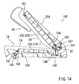
- the back frame 22 (the seat back 20) begins to tilt forwardly toward an intermediate position shown in FIG. 14 .
- the rear bracket 144 ( FIG. 12 ) is rotated because the rear bracket 144 is fixed to the upper arm 36 of the back frame 22. Consequently, the pivot pin 146 pivots or moves counterclockwise around the rotational shaft 32 so that the rear special arm 147 rotates counterclockwise around the connecting shaft 34.
- the rear special arm 147 When the back frame 22 (the seat back 20) is further tilted forwardly toward the retracted position shown in FIG. 15 , the rear special arm 147 further rotates counterclockwise around the connecting shaft 34 so that the contact projection 147c ( FIG. 12 ) of the rear special arm 147 contacts the rear link arm 145. Therefore, the rear link arm 145 pivots or moves counterclockwise around the rotational shaft 32 along with the pivot pin 146. Consequently, as will be apparent from comparing FIGS. 14 and 15 , the side pad support 12C connected to the rear link arm 145 moves toward the backside of the seat cushion 10 while moving rearwardly.
- the side portions 19 of the cushion pad 18 attached to the cushion frame 12 are pulled toward the backside of the seat cushion 10 so that the cushion pad 18 can be effectively flattened.
- the seat cushion 10 may have a reduced thickness when the seat back 22 becomes positioned in the retracted position.
- the lower link arm 154 further rotates counterclockwise around the pivot pin 155. Therefore, the connecting point 157 of the lower link arm 154 further pivots or moves counterclockwise around the pivot pin 155 so as to further move toward or nearer to the rotational shaft 32. Consequently, as will be apparent from comparing FIGS. 14 and 15 , the side pad support 22C connected to the lower link arm 154 further moves toward the backside of the seat back 20 while moving downwardly. Thus, the side portions 29 of the cushion pad 28 attached to the back frame 22 are pulled toward the backside of the seat back 20 so that the cushion pad 28 can be effectively flattened. As a result, the seat back 20 may have a reduced thickness when the seat back 22 becomes positioned in the retracted position.
- the thickness of the seat cushion 10 and the seat back 20 can be respectively effectively reduced when the seat back 20 is tilted from the use position to the retracted position.
- a total thickness of the seat cushion 10 and the seat back 20 can be effectively reduced when the seat 101 is in the retracted condition. Therefore, the seat 101 can be retracted within a reduced or limited retracting space. This may lead to the minimization of a retracting space (not shown) of the seat 101.
- the retractable seat 101 in this embodiment is not designed such that the side portions 19 and 29 of the cushion pad 18 and 28 are laterally or transversely moved when the seat back 20 is tilted. Therefore, the side portions 19 and 29 may have a sufficient side support function.
- the retractable seat 101 is designed such that the thicknesses of both of the seat cushion 10 and the seat back 20 can be reduced.
- the seat 101 can be design changed such that a thickness of only one of the seat cushion 10 and the seat back 20 can be reduced.
- a retractable seat 201 may include the seat cushion 10 and the seat back 20. Similar to the second embodiment, the cushion pad 18 of the seat cushion 10 includes the thickened side portions 19. Also, the cushion pad 28 of the seat back 20 includes the thickened side portions 29. Further, unlike the second embodiment, each of the thickened side portions 29 includes an upper projected portion (i.e., an upper side portion) 29a. As will be appreciated, each of the upper projected portions 29a may preferably be positioned so as to correspond to a shoulder of an occupant (not shown).
- the cushion frame 12 may preferably be constituted of the outer frame member or framework 12A and the inner support member or pad support 12B.
- the inner pad support 12B is connected to the framework 12A via springs 17.
- the back frame 22 may preferably be constituted of the outer frame member or framework 22A and the inner frame member or pad support 22B.
- the pad support 22B is connected to the framework 22A via springs 27.
- the framework 22A of the back frame 22 is provided with a pair of curved upper support members or pad supports 240 attached thereto.
- the upper pad supports 240 may preferably be positioned on both sides of the framework 22A so as to correspond to the upper projected portions 29a of the cushion pads 28.
- each of the upper pad supports 240 may preferably be shaped so as to be substantially identical with the contour of the upper projected portion 29a.
- An upper end of the upper pad support 240 may preferably be rotatably connected to the framework 22A via a hinge pin 241 so that the upper pad support 240 can pivot or rotate forward and rearward therearound. As best shown in FIG.
- the upper pad support 240 is integrally provided with a curved side wall 242 that is positioned adjacent to the framework 22A.
- the side wall 242 is formed with an arcuate guide slot (i.e., a guide mechanism) 243 extending therealong.
- each upper link arm 244 may preferably be rotatably connected to the framework 22A via a hinge pin 245 that is positioned at a lower side of the hinge pin 241.
- the other end of each upper link arm 244 is provided with a guide pin (i.e., the guide mechanism) 246 which slidably engages the guide slot 243.
- the framework 22A of the back frame 22 is further provided with a pair of elongated vertical connecting members or connecting rods (i.e., the linking mechanisms) 250 (one of which is shown).
- Each of the connecting rods 250 may preferably have an upper connecting end 252 and a lower connecting end (i.e. connecting point) 253.
- the upper connecting end 252 may preferably be connected to the guide pin 246 of the upper link arm 244.
- the lower connecting end 253 may preferably be rotatably connected to the lower arm 38 of the cushion frame 12. As will be apparent, the lower connecting end 253 may preferably be displaced upwardly and rearwardly from the rotational shaft 32.
- the guide pin 246 is located in a mid position within the guide slot 243.
- the pad support 240 fully or maximally projects forwardly. That is, the pad support 240 projects forwardly beyond the pad support 22B.
- the upper projected portion 29a may preferably be produced in the thickened side portion 29.
- the back frame 22 (the framework 22A) rotates forward (i.e., counterclockwise) around the rotational shaft 32.
- the back frame 22 (the seat back 20) begins to tilt forwardly toward an intermediate position shown in FIG. 20 .
- the hinge pin 241 of the upper pad support 240 and the hinge pin 245 of the upper link arm 244 are pivoted or moved around the rotational shaft 32.
- the upper connecting end 252 of the connecting rod 250 i.e., the guide pin 246 of the upper link arm 244 is pivoted or moved around the lower connecting end 253 of the connecting rod 250.
- the upper connecting end 252 of the connecting rod 250 may preferably be pulled downwardly (i.e., in the direction shown by arrow in FIG. 23 ) because the lower connecting end 253 is displaced rearwardly from the rotational shaft 32. Consequently, as will be apparent from comparing FIGS. 22 and 23 , the upper link arm 244 rotates counterclockwise around the hinge pin 245.
- the guide pin 246 of the upper link arm 244 slides downward along the guide slot 243 of the upper pad support 240 so that the upper pad support 240 rotates counterclockwise around the hinge pin 241. As a result, the upper pad support 240 substantially moves toward the backside of the seat back 20.
- the upper projected portion 29a of the cushion pad 28 is fully pulled toward the backside of the seat back 20 because the upper pad support 240 corresponds to the upper projected portion 29a.
- the upper projected portion 29a may preferably be eliminated so that the side portion 29 of the cushion pad 28 can be effectively flattened.
- the seat back 20 may have a reduced thickness when the seat back 22 becomes oriented in the retracted position.
- the thickness of the seat back 20 can be respectively effectively reduced when the seat back 20 is tilted from the use position to the retracted position.
- a total thickness of the seat cushion 10 and the seat back 20 can be effectively reduced when the seat 201 is in the retracted condition. Therefore, the seat 201 can be retracted within a reduced or limited retracting space. This may lead to the minimization of a retracting space (not shown) of the seat 201.
- a retractable seat 301 may include the seat cushion 10 and the seat back 20. Similar to the third embodiment, the framework 22A of the back frame 22 is provided with a pair of curved upper pad supports 340 attached thereto (one of which is shown).
- the upper pad supports 340 may preferably be positioned on both sides of the framework 22A so as to correspond to the upper projected portions 29a of the cushion pads 28. Also, each of the upper pad supports 340 may preferably be shaped so as to be substantially identical with the contour of the upper projected portion 29a.
- An upper end of the upper pad support 340 may preferably be rotatably connected to the framework 22A via a hinge pin 341 so that the upper pad support 340 can be rotated forward and rearward therearound.
- the upper pad support 340 is integrally provided with a cam member (i.e., a guide mechanism) 342 that extends downwardly along the rear side of the upper pad support 340.
- a lower end of the upper pad support 340 may preferably be connected to the framework 22A via a spring 360 so that the upper pad support 340 (the cam member 342) can be normally forced counterclockwise around the hinge pin 341.
- the framework 22A of the back frame 22 is also provided with a pair of upper movable members or slide members (i.e., linking mechanisms) 344 (one of which is shown) associated with the cam members 342.
- Each of the slide members 344 includes an upper projected portion (i.e., the guide mechanism) 345 and a lower guide pin 346.
- the projected portion 345 is arranged and constructed to engage a cam surface 342a of the cam member 342.
- the guide pin 346 slidably engages a guide slot 364 that is vertically or longitudinally formed in the framework 22A.
- an upper end of the slide member 344 may preferably be connected to the framework 22A via a return spring 362.
- the return spring 362 is arranged and constructed to upwardly force the slide member 344. As will be easily understood, the return spring 362 may preferably have a spring force greater than the spring 360 of the upper pad support 340.
- the framework 22A of the back frame 22 is further provided with a pair of elongated vertical connecting members or connecting cables (i.e., the linking mechanisms) 350 (one of which is shown).
- An upper end of each connecting cable 350 may preferably be connected to a lower end of the slide member 344.
- a lower end of each connecting cable 350 may preferably be rotatably connected to the lower arm 38 of the cushion frame 12.
- the slide member 344 when the seat 301 is positioned in a use condition, the slide member 344 is retained in an uppermost position by means of the return spring 362. At this time, the projected portion 345 of the slide member 344 may preferably contact an uppermost point of the cam surface 342a of the cam member 342 so that the pad support 340 is fully projected forwardly. Thus, the upper projected portion 29a may preferably be produced in the thickened side portion 29.
- the back frame 22 (the framework 22A) rotates forward (i.e., counterclockwise) around the rotational shaft 32.
- the back frame 22 (the seat back 20) begins to tilt forwardly toward an intermediate position shown in FIG. 26 .
- the guide pin 346 of the slide member 344 is pulled downwardly via the connecting cable 350 so as to slide downwardly within the guide slot 364.
- the slide member 344 slides downwardly against the spring force of the return spring 362. Therefore, the projected portion 345 of the slide member 344 may preferably slide downwardly along the cam surface 342a of the cam member 342. Consequently, the pad support 340 rotates counterclockwise around the hinge pin 341 so as to substantially move toward the backside of the seat back 20 because the upper pad support 340 may preferably be forced toward the framework 22A via the spring 360.
- the upper projected portion 29a of the cushion pad 28 is fully pulled toward the backside of the seat back 20 because the upper pad support 340 corresponds to the upper projected portion 29a.
- the upper projected portion 29a may preferably be eliminated so that the side portion 29 of the cushion pad 28 can be effectively flattened.
- the seat back 20 may have a reduced thickness when the seat back 22 becomes positioned in the retracted position.
- the pad supports 240 and 340 are respectively designed so as to rotate around the hinge pins 241 and 341.
- the pad supports 240 and 340 can be respectively designed so as to linearly slide toward the backside of the seat back 20.
- the present invention can be applied to a seat in which the seat cushion is tilted or raised.
Description
- The present invention relates to retractable seats for a vehicle. More particularly, the present invention relates to retractable seats that can be retracted by tilting seat backs forwardly and superimposing the seat backs on seat cushions.
- A retractable seat of this type is taught, for example, by
Japanese Laid-Open Patent Publication No. 2002-264708 - Typically, the seat includes a seat back and a seat cushion. The seat back is rotatably connected to the seat cushion so as to be tilted. The seat back is provided with a back panel. In the known art, the back panel is arranged and constructed such that a clearance is formed between the seat back and the back panel. Also, the seat back includes a clearance adjusting means. The clearance adjusting means is constructed such that the clearance can be changed when the seat back is tilted forwardly and rearwardly. That is, the clearance adjusting means is constructed such that the clearance can be reduced when the seat back is folded forwardly and that the clearance can be increased when the seat back is raised rearwardly.
- Thus, when the seat back is folded, the clearance is reduced and the total thickness of the seat back and the back panel can be somewhat reduced. As a result, the seat can be retracted within a limited retracting space.
- However, in the retractable seat thus constructed, the total thickness is not so reduced because there is a limit to the changing of the clearance.
-
WO-A-2004/065162 prior art document according to article 54(3) EPC andDE-A-10055205 disclose prior art folding seats. - It is, accordingly, one object of the present teachings to provide an improved, retractable vehicle seat.
- According to the invention there is provided a retractable seat having the features of
claim 1 appended hereto. - According to this retractable seat, when the seat cushion or the seat back is folded, the total thickness of the seat back and the back panel can be effectively reduced. As a result, the seat can be retracted within a limited retracting space.
- Other objects, features, and advantages, of the present invention will be readily understood after reading the following detailed description together with the accompanying drawings and the claims.
-
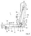
FIG 1 is a side view of a retractable vehicle seat according to a first embodiment of the present invention, illustrating a condition in which a seat back is in a use or raised position; and -
FIG. 2 is a partially omitted side view of the retractable vehicle seat shown inFIG 1 ; and -
FIG. 3 is a side view of the retractable seat, illustrating a condition in which the seat back is started to be tilted forwardly (i.e., a intermediate position of the seat back); and -
FIG 4 is a side view of the retractable seat, illustrating a condition in which the seat back is in a retracted position; and -
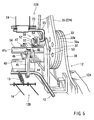
FIG 5 is an enlarged perspective view of a connecting portion of a back frame and a cushion frame; and -
FIG 6 is a perspective view of an arm used in the retractable seat; and -
FIG. 7 is a side view of support members and a link mechanism used in the retractable seat, illustrating a condition which corresponds to the condition shown inFIG 2 ; and -
FIG 8 is a side view of the support members and the link mechanism, illustrating a condition which corresponds to the condition shown inFIG 3 ; and -
FIG 9 is a side view of the support members and the link mechanism, illustrating a condition which corresponds to the condition shown inFIG 4 ; and -
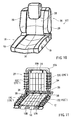
FIG. 10 is a perspective view of a retractable vehicle seat according to a second embodiment of the present invention; and -
FIG. 11 is a partially omitted perspective view of the retractable vehicle seat; and -
FIG. 12 is a partially enlarged perspective view ofFIG. 11 ; and -
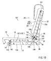
FIG. 13 is a partially omitted side view of the retractable vehicle seat, illustrating a condition in which a seat back is in a use or raised position; and -
FIG. 14 is a side view of the retractable seat, illustrating a condition in which the seat back is started to be tilted forwardly (i.e., a intermediate position of the seat back); and -
FIG. 15 is a side view of the retractable seat, illustrating a condition in which the seat back is in a retracted position. -
FIG. 16 is a perspective view of a retractable vehicle seat according to a third embodiment of the present invention; and -
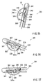
FIG. 17 is a partially omitted perspective view of the retractable vehicle seat; and -
FIG. 18 is a partially enlarged perspective view ofFIG. 17 ; and -
FIG. 19 is a partially omitted side view of the retractable vehicle seat, illustrating a condition in which a seat back is in a use or raised position; and -
FIG. 20 is a side view of the retractable seat, illustrating a condition in which the seat back is started to be tilted forwardly (i.e., a intermediate position of the seat back); and -
FIG. 21 is a side view of the retractable seat, illustrating a condition in which the seat back is in a retracted position. -
FIG. 22 is a partially enlarged view ofFIG. 19 ; and -
FIG. 23 is a partially enlarged view ofFIG. 20 ; and -
FIG. 24 is a partially enlarged view ofFIG. 21 ; and -
FIG. 25 is a view similar toFIG. 22 , illustrating a retractable vehicle seat according to a fourth embodiment of the present invention; and -
FIG. 26 is a view similar toFIG. 23 ; and -
FIG. 27 is a view similar toFIG. 24 . - Four detailed representative embodiments of the present teachings will now be described in further detail with reference to
FIGS. 1 to 27 . - The first detailed representative embodiment will now described with reference to
FIGS. 1 to 9 . - As shown in
FIGS. 1 to 4 , a retractable seat (rear seat) 1 may include aseat cushion 10 and a seat back 20. Theseat cushion 10 is generally supported on a vehicle floor (not shown). Theseat cushion 10 may preferably be constituted of acushion frame 12, acushion pad 18 attached to thecushion frame 12, and a skin layer orouter cover 10a (FIG. 1 ) that covers or encloses thepad 18. Similarly, theseat back 20 may preferably be constituted of aback frame 22, aback pad 28 attached to theback frame 22, and a skin layer orouter cover 20a (FIG. 1 ) that covers or encloses thepad 28. - The
cushion frame 12 of theseat cushion 10 is rotatably connected to theback frame 22 of theseat back 20 via a pair of seat reclining devices 30 (one of which is shown). The recliningdevice 30, for example, can tilt the seat back 20 forwardly (i.e., counterclockwise) from a normal or use position (FIGS. 1 and2 ), superimpose the same on theseat cushion 10, and retain the seat back 20 in that position, i.e., a retracted position (FIG. 4 ). As will be appreciated, theretractable seat 1 may preferably be designed so as to be retracted into a retracting space S formed in a vehicle floor F when theseat back 20 is superimposed on theseat cushion 10. - Typically, the seat reclining
devices 30 allow theback frame 22 to be rotated forward and rearward (i.e., counterclockwise and clockwise) around rotational shafts (i.e., rotational axes) 32, and to be locked in a desired rotational position. This allows theseat back 20 to be adjusted to a desired tilting position relative to theseat cushion 10. As will be appreciated, if the seat recliningdevices 30 are of motor-driven types, theback frame 22 can be rotated forward and rearward by normally and reversely driving a motor (not shown). - As shown in
FIG. 5 , each of the seat recliningdevices 30 includes a pair of opposing disk-like housings, i.e., afirst housing 30a and asecond housing 30b, that are arranged and constructed to rotate around therotational shaft 32. Thefirst housing 30a is attached to alower arm 38 fixed to the rear end of the cushion frame 12 (theframework 12A) by means of an appropriate bonding means such as welding. Thesecond housing 30b is attached to anupper arm 36 fixed to the lower end of theback frame 22 by means of an appropriate bonding means such as welding. The first andsecond housings second housing 30b can move or rotate relative to thefirst housing 30a around therotational shaft 32. Further, the respectiverotational shafts 32 are interconnected via a connectingshaft 34. - As shown in
FIGS. 1 to 4 , thecushion frame 12 may preferably be constituted of an outer frame member orframework 12A and a central or inner support member orpad support 12B for supporting a substantial portion of thecushion pad 18 from a backside (under surface) thereof. Similarly, theback frame 22 may preferably be constituted of an outer frame member orframework 22A and a central or inner frame member orpad support 22B for supporting thecushion pad 28 from a backside (rear surface) thereof. - Further, conventionally, the
frameworks frameworks frameworks FIG. 5 , which will be hereinafter described). - As partly shown in
FIG. 5 , thepad support 12B of thecushion frame 12 may preferably be constituted of an outerrectangular support frame 13 and aninner support net 14. Thesupport net 14 may preferably be formed as a crosswise combination of a plurality of spring wires. Further, thesupport net 14 may preferably be resiliently connected to thesupport frame 13 by means of plurality of coil springs 15 (one of which is shown). Similarly, thepad support 22B of theback frame 22 may preferably be constituted of an outerrectangular support frame 23 and aninner support net 24. Thesupport net 24 may preferably be formed as a crosswise combination of a plurality of spring wires. Further, unlike thesupport net 14, thesupport net 24 may preferably be directly connected to thesupport frame 23. - As shown in
FIGS. 5 and7 to 9 , each of thefirst linking mechanisms 40 includes afront link arm 42, afront bracket 41 that is fixed to theframework 12A, a reardrive link arm 45, a rearspecial arm 47, and arear bracket 44 that is fixed to theupper arm 36 of the back frame 22 (theframework 22A). Thefront link arm 42 may preferably be rotatably connected to afront bracket 41 via apivot pin 43. Further, a free end of thefront link arm 42 may preferably be pivotally connected to thesupport frame 13 of thepad support 12B. - The
rear link arm 45 may preferably be rotatably connected to therear bracket 44 via apivot pin 46 interleaving the rearspecial arm 47 therebetween. As will be apparent, thepivot pin 46 is not aligned with therotational shaft 32 of the reclining device 30 (i.e., a rotational axis of the seat back 20) and is displaced forwardly therefrom. In addition, aspacer 48 may preferably be interleaved between therear link arm 45 and the rearspecial arm 47 so that therear link arm 45 and the rearspecial arm 47 can be appropriately positioned along thepivot pin 46. Further, a free end of therear link arm 45 is movably connected to thesupport frame 13 of thepad support 12B. - Thus, the
support frame 13 of thepad support 12B may preferably be supported by at least four supporting points. - As shown in
FIG. 6 , the rearspecial arm 47 includes first and second throughholes contact projection 47c. The first and second throughholes pivot pin 46 and the connectingshaft 34. Therefore, when theback frame 22 is forwardly rotated around therotational shaft 32 connected to the connectingshaft 34 so that therear bracket 44 is pivoted around therotational shaft 32, the rearspecial arm 47 may also preferably rotate around the connecting shaft 34 (counterclockwise inFIGS. 7-9 ). As a result, thecontact projections 47c of the rearspecial arms 47 contacts the rear link arms 45 (FIG. 9 ), thereby urging eachrear link arm 45 such that therear link arm 45 rotates in the corresponding direction (i.e., counterclockwise). - As shown in
FIGS. 5 and7 to 9 , each of thesecond linking mechanisms 50 includes anupper link bracket 51 that is fixed to theframework 22A, a lowerdrive link arm 54, and alower bracket 53 that is fixed to the lower arm 38 (theframework 12A of the cushion frame 12). A free end of theupper link bracket 51 may preferably engage thesupport frame 23 of thepad support 22B via aspring 52. - The
lower link arm 54 may preferably be rotatably connected to thelower bracket 53 via apivot pin 55. Further, a free end of thelower link arm 54 is pivotally connected to thesupport frame 23 of thepad support 22B via a connectingarm 25 that is coupled to the support frame 23 (FIG. 5 ). That is, thelower link arm 54 is pivotally connected to the connectingarm 25 at a connectingpoint 57 that is displaced from the pivot pin 55 (i.e., a rotational axis of the lower link arm 54). - Thus, the
support frame 23 of thepad support 22B may preferably be supported by at least four supporting points. - Further, as shown in
FIG. 2 , when theseat 1 is positioned in a use condition, thepad support 12B is positioned in substantially an uppermost position. Also, thepad support 22B is positioned in substantially a forwardmost position. Thus, theseat cushion 10 and the seat back 20 may respectively have a maximum thickness. - Next, an operation for switching the
seat 1 from the use condition to a retracted condition will be described with reference to, in particular,FIGS. 2 to 4 and7 to 9 . Further, it is noted that the motion of thecushion frame 12 and theback frame 22 is substituted for the corresponding motion of theseat cushion 10 and the seat back 20. - In the use condition of the
seat 1 shown inFIGS. 2 and7 , when theseat reclining device 30 is operated or driven, the back frame 22 (theframework 22A) rotates forward (i.e., counterclockwise) around therotational shaft 32. As a result, the back frame 22 (the seat back 20) begins to tilt forwardly toward an intermediate position shown inFIGS. 3 and8 . When theback frame 22 is tilted in this direction, the rear bracket 44 (FIG. 5 ) is rotated because therear bracket 44 is fixed to theupper arm 36 of theback frame 22. Consequently, thepivot pin 46 pivots or moves counterclockwise around therotational shaft 32 so that the rearspecial arm 47 rotates counterclockwise around the connectingshaft 34. - At this time, the
lower link arm 54 rotates counterclockwise around thepivot pin 55. Therefore, the connectingpoint 57 of thelower link arm 54 and the connectingarm 25 pivots or moves counterclockwise around thepivot pin 55 so as to move toward or nearer to therotational shaft 32 because the connectingpoint 57 is displaced from thepivot pin 55. Consequently, as will be apparent from comparingFIGS. 2 and3 , thepad support 22B connected to thelower link arm 54 via the connectingarm 25 moves toward a backside of the seat back 20 while moving downwardly. - When the back frame 22 (the seat back 20) is further tilted forwardly toward the retracted position shown in
FIGS. 4 and9 , the rearspecial arm 47 further rotates counterclockwise around the connectingshaft 34 so that thecontact projection 47c of the rearspecial arm 47 contacts therear link arm 45. Therefore, therear link arm 45 pivots or moves counterclockwise around therotational shaft 32 along with thepivot pin 46. Consequently, as will be apparent from comparingFIGS. 3 and4 , thepad support 12B (the support frame 13) connected to therear link arm 45 via the coil springs 15 moves toward a backside of theseat cushion 10 while moving rearwardly. Thus, thecushion pad 18 attached to thecushion frame 12 is pulled toward the backside of theseat cushion 10. As a result, theseat cushion 10 may have a reduced thickness when the seat back 22 becomes positioned in the retracted position. - At this time, the
lower link arm 54 further rotates counterclockwise around thepivot pin 55. Therefore, the connectingpoint 57 of thelower link arm 54 and the connectingarm 25 further pivots or moves counterclockwise around thepivot pin 55 so as to further move toward or nearer to therotational shaft 32. Consequently, as will be apparent from comparingFIGS. 3 and4 , thepad support 22B connected to thelower link arm 54 via the connectingarm 25 further moves toward the backside of the seat back 20 while moving downwardly. Thus, thecushion pad 28 attached to theback frame 22 is pulled toward the backside of the seat back 20. As a result, the seat back 20 may have a reduced thickness when the seat back 22 becomes positioned in the retracted position. - According to the present embodiment, the thickness of the
seat cushion 10 and the seat back 20 can be respectively effectively reduced when the seat back 20 is tilted from the use position to the retracted position. As a result, a total thickness of theseat cushion 10 and the seat back 20 can be effectively reduced when theseat 1 is in the retracted condition. Therefore, theseat 1 can be retracted within a reduced or limited retracting space. This may lead to minimization of the retracting space S of theseat 1. Typically, the reduction of each of thicknesses of theseat cushion 10 and the seat back 20 is approximately 10-35mm. - Further, the first and
second linking mechanisms back frame 22 rotates rearward (i.e., clockwise) from the use position around therotational shaft 32. Therefore, the thicknesses of theseat cushion 10 and the seat back 20 cannot be respectively reduced even if the seat back 20 is tilted rearward from the use condition. - According to the present embodiment, the
retractable seat 1 is designed such that the thicknesses of both of theseat cushion 10 and the seat back 20 can be reduced. However, if necessary, theseat 1 can be design changed such that a thickness of only one of theseat cushion 10 and the seat back 20 can be reduced. - The second detailed representative embodiment will now described with reference to
FIGS. 10 to 15 . - Because the second embodiment relates to the first embodiment, only constructions and elements that are different from the first embodiment will be explained in detail. Elements that are the same in the first and second embodiments will be identified by the same reference numerals and detailed description of such elements may be omitted.
- As shown in
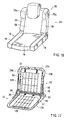
FIGS. 10 and 11 , aretractable seat 101 may include theseat cushion 10 and the seat back 20. However, unlike the first embodiment, thecushion pad 18 of theseat cushion 10 includes thickenedside portions 19. Also, thecushion pad 28 of the seat back 20 includes thickenedside portions 29. Thecushion frame 12 may preferably be constituted of the outer frame member orframework 12A and the inner support member orpad support 12B. Unlike the first embodiment, theinner pad support 12B is integrally connected to theframework 12A. Thecushion frame 12 may further include a side support member orpad support 12C for supporting the thickenedside portions 19 of thecushion pad 18 from a backside (under surface) thereof. Theside pad support 12C may preferably be separate from theframework 12A and theinner pad support 12B. Similarly, theback frame 22 may preferably be constituted of the outer frame member orframework 22A and the inner frame member orpad support 22B. Unlike the first embodiment, thepad support 22B is integrally connected to theframework 22A. Theback frame 22 may further include a side support member orpad support 22C for supporting the thickenedside portions 29 of thecushion pad 28 from a backside (rear surface) thereof. Theside pad support 22C may preferably be separate from theframework 22A and theinner pad support 22B. - In this embodiment, the side pad supports 12C and 22C may preferably be linked to the
frameworks - As shown in
FIG. 11 , unlike the first embodiment, theinner pad support 12B of thecushion frame 12 may preferably be constituted of only theinner support net 14. Similarly, theinner pad support 22B of theback frame 22 may preferably be constituted of only theinner support net 24. - As best shown in
FIG. 11 , theside pad support 12C of thecushion frame 12 may preferably be formed as a combination of a plurality of spring wires. Theside pad support 12C may preferably include a pair of three-dimensionalside support portions 12C'. Theside support portions 12C' may preferably be shaped so as to be substantially identical with the contour of theside portions 19 of thecushion pad 18. Theside pad support 12C thus constructed may preferably be positioned on theframework 12A such that theside support portions 12C' correspond to the side portions of theframework 12A. Similarly, theside pad support 22C of theback frame 22 may preferably be formed as a combination of a plurality of spring wires. Theside pad support 22C may preferably include a pair of three-dimensionalside support portions 22C'. Theside support portions 22C' may preferably be shaped so as to be substantially identical with the contour of theside portions 29 of thecushion pad 28. Theside pad support 22C thus constructed may preferably be positioned on theframework 22A such that theside support portions 22C' correspond to the side portions of theframework 22A. - As shown in
FIGS. 12 to 15 , each of thefirst linking mechanisms 140 includes afront link arm 142, afront bracket 141 that is fixed to theframework 12A, a reardrive link arm 145, a rearspecial arm 147, and arear bracket 144 that is fixed to theupper arm 36 of the back frame 22 (theframework 22A). Thefront link arm 142 may preferably be rotatably connected to afront bracket 141 via apivot pin 143. Further, a free end of thefront link arm 142 may preferably be movably connected to theside pad support 12C. - The
rear link arm 145 may preferably be rotatably connected to therear bracket 144 via apivot pin 146 interleaving the rearspecial arm 147 therebetween. As will be apparent, thepivot pin 146 is not aligned with therotational shaft 32 of the reclining device 30 (i.e., a rotational axis of the seat back 20) and is displaced forwardly therefrom. A free end of therear link arm 145 is pivotally connected to theside pad support 12C. - Thus, the
side pad support 12C of thecushion frame 12 may preferably be supported by at least four supporting points. - The rear
special arm 147 substantially has the same construction as the rearspecial arm 47 of the first embodiment. Therefore, when theback frame 22 is forwardly rotated around therotational shaft 32 connected to the connectingshaft 34 so that therear bracket 144 is pivoted around therotational shaft 32, the rearspecial arm 147 may also preferably rotate around the connecting shaft 34 (counterclockwise inFIGS. 13-15 ). As a result, thecontact projections 147c of the rearspecial arms 147 contacts the rear link arms 145 (FIG. 9 ), thereby urging eachrear link arm 145 such that therear link arm 145 rotates in the corresponding direction (i.e., counterclockwise). - As shown in
FIGS. 12 to 15 , each of thesecond linking mechanisms 150 includes anupper link bracket 151 that is fixed to theframework 22A, a lowerdrive link arm 154, and alower bracket 153 that is fixed to the lower arm 38 (theframework 12A of the cushion frame 12). A free end of theupper bracket 151 may preferably engage theside pad support 22C of theback frame 22. - The
lower link arm 154 may preferably be rotatably connected to thelower bracket 153 via apivot pin 155. Further, a free end of thelower link arm 154 is pivotally connected to theside pad support 22C at a connectingpoint 157. - Thus, the
side pad support 22C of theback frame 22 may preferably be supported by at least four supporting points. - Further, as shown in
FIG. 13 , when theseat 101 are positioned in a use condition, theside support portions 12C' ofside pad support 12C is positioned in substantially an uppermost position. Also, theside support portions 22C' ofside pad support 22C are positioned in substantially a forwardmost position. Thus, theseat cushion 10 and the seat back 20 may respectively have a maximum thickness. - Next, an operation for switching the
seat 101 from the use condition to a retracted condition will be described with particular reference toFIGS. 13 to 15 . - In the use condition of the
seat 101 shown inFIG. 13 , when theseat reclining device 30 is operated or driven, the back frame 22 (theframework 22A) rotates forward (i.e., counterclockwise) around therotational shaft 32. As a result, the back frame 22 (the seat back 20) begins to tilt forwardly toward an intermediate position shown inFIG. 14 . When theback frame 22 is tilted in this direction, the rear bracket 144 (FIG. 12 ) is rotated because therear bracket 144 is fixed to theupper arm 36 of theback frame 22. Consequently, thepivot pin 146 pivots or moves counterclockwise around therotational shaft 32 so that the rearspecial arm 147 rotates counterclockwise around the connectingshaft 34. - At this time, the
lower link arm 154 rotates counterclockwise around thepivot pin 155. Therefore, the connectingpoint 157 of thelower link arm 154 and theside pad support 22C pivots or moves counterclockwise around thepivot pin 155 so as to move toward or nearer to therotational shaft 32. Consequently, as will be apparent from comparingFIGS. 13 and14 , theside pad support 22C connected to thelower link arm 154 moves toward the backside of the seat back 20 while moving downwardly. - When the back frame 22 (the seat back 20) is further tilted forwardly toward the retracted position shown in
FIG. 15 , the rearspecial arm 147 further rotates counterclockwise around the connectingshaft 34 so that thecontact projection 147c (FIG. 12 ) of the rearspecial arm 147 contacts therear link arm 145. Therefore, therear link arm 145 pivots or moves counterclockwise around therotational shaft 32 along with thepivot pin 146. Consequently, as will be apparent from comparingFIGS. 14 and15 , theside pad support 12C connected to therear link arm 145 moves toward the backside of theseat cushion 10 while moving rearwardly. Thus, theside portions 19 of thecushion pad 18 attached to thecushion frame 12 are pulled toward the backside of theseat cushion 10 so that thecushion pad 18 can be effectively flattened. As a result, theseat cushion 10 may have a reduced thickness when the seat back 22 becomes positioned in the retracted position. - At this time, the
lower link arm 154 further rotates counterclockwise around thepivot pin 155. Therefore, the connectingpoint 157 of thelower link arm 154 further pivots or moves counterclockwise around thepivot pin 155 so as to further move toward or nearer to therotational shaft 32. Consequently, as will be apparent from comparingFIGS. 14 and15 , theside pad support 22C connected to thelower link arm 154 further moves toward the backside of the seat back 20 while moving downwardly. Thus, theside portions 29 of thecushion pad 28 attached to theback frame 22 are pulled toward the backside of the seat back 20 so that thecushion pad 28 can be effectively flattened. As a result, the seat back 20 may have a reduced thickness when the seat back 22 becomes positioned in the retracted position. - According to the present embodiment, similar to the first embodiment, the thickness of the
seat cushion 10 and the seat back 20 can be respectively effectively reduced when the seat back 20 is tilted from the use position to the retracted position. As a result, a total thickness of theseat cushion 10 and the seat back 20 can be effectively reduced when theseat 101 is in the retracted condition. Therefore, theseat 101 can be retracted within a reduced or limited retracting space. This may lead to the minimization of a retracting space (not shown) of theseat 101. - Further, the
retractable seat 101 in this embodiment is not designed such that theside portions cushion pad side portions - According to the present embodiment, the
retractable seat 101 is designed such that the thicknesses of both of theseat cushion 10 and the seat back 20 can be reduced. However, similar to the first embodiment, if necessary, theseat 101 can be design changed such that a thickness of only one of theseat cushion 10 and the seat back 20 can be reduced. - The third detailed representative embodiment will now described with reference to
FIGS. 16 to 24 . - Because the third embodiment relates to the second embodiment, only constructions and elements that are different from the second embodiment will be explained in detail. Elements that are the same in the second and third embodiments will be identified by the same reference numerals and detailed description of such elements may be omitted.
- As shown in
FIGS. 16 and 17 , aretractable seat 201 may include theseat cushion 10 and the seat back 20. Similar to the second embodiment, thecushion pad 18 of theseat cushion 10 includes the thickenedside portions 19. Also, thecushion pad 28 of the seat back 20 includes the thickenedside portions 29. Further, unlike the second embodiment, each of the thickenedside portions 29 includes an upper projected portion (i.e., an upper side portion) 29a. As will be appreciated, each of the upper projectedportions 29a may preferably be positioned so as to correspond to a shoulder of an occupant (not shown). - The
cushion frame 12 may preferably be constituted of the outer frame member orframework 12A and the inner support member orpad support 12B. Theinner pad support 12B is connected to theframework 12A via springs 17. Similarly, theback frame 22 may preferably be constituted of the outer frame member orframework 22A and the inner frame member orpad support 22B. Thepad support 22B is connected to theframework 22A via springs 27. - As best shown in
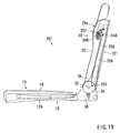
FIGS. 17 and18 , theframework 22A of theback frame 22 is provided with a pair of curved upper support members or pad supports 240 attached thereto. As will be apparent, the upper pad supports 240 may preferably be positioned on both sides of theframework 22A so as to correspond to the upper projectedportions 29a of thecushion pads 28. Also, each of the upper pad supports 240 may preferably be shaped so as to be substantially identical with the contour of the upper projectedportion 29a. An upper end of theupper pad support 240 may preferably be rotatably connected to theframework 22A via ahinge pin 241 so that theupper pad support 240 can pivot or rotate forward and rearward therearound. As best shown inFIG. 18 , theupper pad support 240 is integrally provided with acurved side wall 242 that is positioned adjacent to theframework 22A. Theside wall 242 is formed with an arcuate guide slot (i.e., a guide mechanism) 243 extending therealong. - As shown in
FIG. 18 , theframework 22A of theback frame 22 is also provided with a pair of upper movable members or link arms (i.e., linking mechanisms) 244 associated with the upper pad supports 240. One end of eachupper link arm 244 may preferably be rotatably connected to theframework 22A via ahinge pin 245 that is positioned at a lower side of thehinge pin 241. The other end of eachupper link arm 244 is provided with a guide pin (i.e., the guide mechanism) 246 which slidably engages theguide slot 243. - As shown in
FIG. 18 , theframework 22A of theback frame 22 is further provided with a pair of elongated vertical connecting members or connecting rods (i.e., the linking mechanisms) 250 (one of which is shown). Each of the connectingrods 250 may preferably have an upper connectingend 252 and a lower connecting end (i.e. connecting point) 253. The upper connectingend 252 may preferably be connected to theguide pin 246 of theupper link arm 244. The lower connectingend 253 may preferably be rotatably connected to thelower arm 38 of thecushion frame 12. As will be apparent, the lower connectingend 253 may preferably be displaced upwardly and rearwardly from therotational shaft 32. - As shown in
FIGS. 19 and22 , when theseat 201 is positioned in a use condition, theguide pin 246 is located in a mid position within theguide slot 243. At this time, thepad support 240 fully or maximally projects forwardly. That is, thepad support 240 projects forwardly beyond thepad support 22B. Thus, the upper projectedportion 29a may preferably be produced in the thickenedside portion 29. - Next, an operation for switching the
seat 201 from the use condition to a retracted condition will be described in particular with reference toFIGS. 19 to 24 . - In the use condition of the
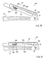
seat 201 shown inFIG. 19 , when theseat reclining device 30 is operated or driven, the back frame 22 (theframework 22A) rotates forward (i.e., counterclockwise) around therotational shaft 32. As a result, the back frame 22 (the seat back 20) begins to tilt forwardly toward an intermediate position shown inFIG. 20 . When theback frame 22 is tilted in this direction, thehinge pin 241 of theupper pad support 240 and thehinge pin 245 of theupper link arm 244 are pivoted or moved around therotational shaft 32. Also, the upper connectingend 252 of the connecting rod 250 (i.e., theguide pin 246 of the upper link arm 244) is pivoted or moved around the lower connectingend 253 of the connectingrod 250. At this time, the upper connectingend 252 of the connectingrod 250 may preferably be pulled downwardly (i.e., in the direction shown by arrow inFIG. 23 ) because the lower connectingend 253 is displaced rearwardly from therotational shaft 32. Consequently, as will be apparent from comparingFIGS. 22 and 23 , theupper link arm 244 rotates counterclockwise around thehinge pin 245. - Upon rotation of the
upper link arm 244, theguide pin 246 of theupper link arm 244 slides downward along theguide slot 243 of theupper pad support 240 so that theupper pad support 240 rotates counterclockwise around thehinge pin 241. As a result, theupper pad support 240 substantially moves toward the backside of the seat back 20. - When the back frame 22 (the seat back 20) is further tilted forwardly toward the retracted position shown in
FIG. 21 , the upper connectingend 252 of the connectingrod 250 is further pulled downwardly so that theupper link arm 244 further rotates counterclockwise around thehinge pin 245. Upon further rotation of theupper link arm 244, theguide pin 246 of theupper link arm 244 further slides downward along theguide slot 243 of theupper pad support 240 so that theupper pad support 240 further rotates counterclockwise around thehinge pin 241. As a result, theupper pad support 240 substantially moves further toward the backside of the seat back 20. - Thus, when the
back frame 22 is tilted in the retracted position, the upper projectedportion 29a of thecushion pad 28 is fully pulled toward the backside of the seat back 20 because theupper pad support 240 corresponds to the upper projectedportion 29a. As a result, the upper projectedportion 29a may preferably be eliminated so that theside portion 29 of thecushion pad 28 can be effectively flattened. As a result, the seat back 20 may have a reduced thickness when the seat back 22 becomes oriented in the retracted position. - According to the present embodiment, the thickness of the seat back 20 can be respectively effectively reduced when the seat back 20 is tilted from the use position to the retracted position. As a result, a total thickness of the
seat cushion 10 and the seat back 20 can be effectively reduced when theseat 201 is in the retracted condition. Therefore, theseat 201 can be retracted within a reduced or limited retracting space. This may lead to the minimization of a retracting space (not shown) of theseat 201. - The fourth detailed representative embodiment will now described with reference to
FIGS. 25 to 27 . - Because the fourth embodiment relates to the third embodiment, only constructions and elements that are different from the third embodiment will be explained in detail. Elements that are the same in the third and fourth embodiments will be identified by the same reference numerals and detailed description of such elements may be omitted.
- As shown in
FIGS. 25 to 27 , aretractable seat 301 may include theseat cushion 10 and the seat back 20. Similar to the third embodiment, theframework 22A of theback frame 22 is provided with a pair of curved upper pad supports 340 attached thereto (one of which is shown). The upper pad supports 340 may preferably be positioned on both sides of theframework 22A so as to correspond to the upper projectedportions 29a of thecushion pads 28. Also, each of the upper pad supports 340 may preferably be shaped so as to be substantially identical with the contour of the upper projectedportion 29a. An upper end of theupper pad support 340 may preferably be rotatably connected to theframework 22A via ahinge pin 341 so that theupper pad support 340 can be rotated forward and rearward therearound. Theupper pad support 340 is integrally provided with a cam member (i.e., a guide mechanism) 342 that extends downwardly along the rear side of theupper pad support 340. A lower end of theupper pad support 340 may preferably be connected to theframework 22A via aspring 360 so that the upper pad support 340 (the cam member 342) can be normally forced counterclockwise around thehinge pin 341. - The
framework 22A of theback frame 22 is also provided with a pair of upper movable members or slide members (i.e., linking mechanisms) 344 (one of which is shown) associated with thecam members 342. Each of theslide members 344 includes an upper projected portion (i.e., the guide mechanism) 345 and alower guide pin 346. The projectedportion 345 is arranged and constructed to engage acam surface 342a of thecam member 342. Also, theguide pin 346 slidably engages aguide slot 364 that is vertically or longitudinally formed in theframework 22A. Further, an upper end of theslide member 344 may preferably be connected to theframework 22A via areturn spring 362. Thereturn spring 362 is arranged and constructed to upwardly force theslide member 344. As will be easily understood, thereturn spring 362 may preferably have a spring force greater than thespring 360 of theupper pad support 340. - The
framework 22A of theback frame 22 is further provided with a pair of elongated vertical connecting members or connecting cables (i.e., the linking mechanisms) 350 (one of which is shown). An upper end of each connectingcable 350 may preferably be connected to a lower end of theslide member 344. Although not shown inFIGS. 25 to 27 , similar to the third embodiment, a lower end of each connectingcable 350 may preferably be rotatably connected to thelower arm 38 of thecushion frame 12. - As shown in
FIG. 25 , when theseat 301 is positioned in a use condition, theslide member 344 is retained in an uppermost position by means of thereturn spring 362. At this time, the projectedportion 345 of theslide member 344 may preferably contact an uppermost point of thecam surface 342a of thecam member 342 so that thepad support 340 is fully projected forwardly. Thus, the upper projectedportion 29a may preferably be produced in the thickenedside portion 29. - Next, an operation for switching the
seat 301 from the use condition to a retracted condition will be described with reference toFIGS. 25 to 27 . - In the use condition of the
seat 301 shown inFIG. 25 , when theseat reclining device 30 is operated or driven, the back frame 22 (theframework 22A) rotates forward (i.e., counterclockwise) around therotational shaft 32. As a result, the back frame 22 (the seat back 20) begins to tilt forwardly toward an intermediate position shown inFIG. 26 . When theback frame 22 is tilted in this direction, theguide pin 346 of theslide member 344 is pulled downwardly via the connectingcable 350 so as to slide downwardly within theguide slot 364. As a result, theslide member 344 slides downwardly against the spring force of thereturn spring 362. Therefore, the projectedportion 345 of theslide member 344 may preferably slide downwardly along thecam surface 342a of thecam member 342. Consequently, thepad support 340 rotates counterclockwise around thehinge pin 341 so as to substantially move toward the backside of the seat back 20 because theupper pad support 340 may preferably be forced toward theframework 22A via thespring 360. - When the back frame 22 (the seat back 20) is further tilted forwardly toward the retracted position shown in
FIG. 27 , theguide pin 346 of theslide member 344 is further pulled downwardly via the connectingcable 350 so that theslide member 344 further slides downwardly against the spring force of thereturn spring 362. Therefore, the projectedportion 345 of theslide member 344 further slides downwardly along thecam surface 342a of thecam member 342 so that thepad support 340 further rotates counterclockwise around thehinge pin 341. As a result, thepad support 340 substantially moves further toward the backside of the seat back 20. - Thus, when the
back frame 22 is tilted to the retracted position, the upper projectedportion 29a of thecushion pad 28 is fully pulled toward the backside of the seat back 20 because theupper pad support 340 corresponds to the upper projectedportion 29a. As a result, the upper projectedportion 29a may preferably be eliminated so that theside portion 29 of thecushion pad 28 can be effectively flattened. As a result, the seat back 20 may have a reduced thickness when the seat back 22 becomes positioned in the retracted position. - In the third and fourth embodiments, the pad supports 240 and 340 are respectively designed so as to rotate around the hinge pins 241 and 341. However, the pad supports 240 and 340 can be respectively designed so as to linearly slide toward the backside of the seat back 20.
- Further, in the first to fourth embodiments, although a retractable seat in which the seat back is tilted or folded is exemplified, the present invention can be applied to a seat in which the seat cushion is tilted or raised.
- Representative examples of the present invention have been described in detail with reference to the attached drawings. This detailed description is merely intended to teach a person of skill in the art further details for practicing preferred aspects of the present teachings and is not intended to limit the scope of the invention. Only the claims define the scope of the claimed invention. Therefore, combinations of features and steps disclosed in the foregoing detail description may not be necessary to practice the invention in the broadest sense, and are instead taught merely to particularly describe detailed representative examples of the invention. Moreover, the various features taught in this specification may be combined in ways that are not specifically enumerated in order to obtain additional useful embodiments of the present teachings.
Claims (14)
- A retractable seat (1; 101; 201; 301) comprising a seat cushion (10) and a seat back (20) rotatably supported on the seat cushion in which one of the seat cushion and the seat back is arranged and constructed to be folded onto the other of the seat cushion and the seat back, at least one of the seat cushion and the seat back comprising:a frame (12, 22),a cushion pad (18, 28), anda linking mechanism (40, 50; 140, 150; 244, 250; 344, 350),wherein the frame comprises a framework (12A, 22A) and a support member (12B, 22B; 12C, 22C; 240; 340) that supports the cushion pad from a backside of the cushion pad, andwherein the linking mechanism (40, 50; 140, 150; 244, 250; 344, 350) movably interconnects the framework (12A, 22A) and the support member (12B, 22B; 12C, 22C; 240; 340) and is arranged and constructed to move the support member toward a backside of the at least one of the seat cushion and the seat back when the seat cushion or the seat back is tilted toward a retracted position,characterized in that the linking mechanism (50; 150) is arranged and constructed to connect the support member (22B; 22C) of one of the seat cushion and the seat back to the framework (12A) of the other of the seat cushion and the seat back at a connecting point (57; 157) that is displaced from a rotational axis (32) of the framework of the seat cushion or the seat back,and in that the linking mechanism (50; 150) is arranged and constructed such that when the seat cushion or the seat back is tilted toward the retracted position, the connecting point (57; 157) moves nearer to the rotational axis, thereby moving the support member in a thickness direction of the seat cushion or the seat back.
- A retractable seat as defined in claim 1, wherein the linking mechanism (50; 150) comprises a link arm (54; 154) that is positioned in the connecting point (57; 157) of the support member and the framework, and wherein the link arm (54; 154) is rotatably connected to the support member and the framework.
- A retractable seat as defined in claim 1, wherein the linking mechanism (50) comprises a connecting arm (25) that is arranged and constructed to rotate when the seat cushion or the seat back is tilted, and wherein the connecting arm (25) is connected to the support member of the seat cushion or the seat back.
- A retractable seat as defined in claim 3, wherein the linking mechanism (50) comprises a link bracket (51) that is positioned in a side opposite to a rotational axis (32) of the framework of the seat cushion or the seat back and is rotatably connected to the framework, wherein the link bracket (51) has a free end that is connected to the support member (22B), and wherein the connecting arm (25) is arranged and constructed to pull the support member (22B) of the seat cushion or the seat back toward the rotational axis (32) of the framework of the seat cushion or the seat back when the seat cushion or the seat back is tilted toward the retracted position.
- A retractable seat as defined in any of claims 1-4 wherein the support member comprises a central support member (12B, 22B) that is separated from the framework, and wherein the central support member is arranged and constructed to support a substantial portion of the cushion pad (18, 28).
- A retractable seat as defined in any of claims 1-4 wherein the support member comprises a side support member (12C, 22C) that is separated from the framework, and wherein the side support member is arranged and constructed to support a side portion (19, 29) of the cushion pad (18, 28).
- A retractable seat as defined in claim 1 wherein at least one of the seat cushion and the seat back comprises the seat back (20), wherein the support member comprises an upper support member (240; 340) that supports an upper side portion (29a) of the cushion pad (28) and wherein the linking mechanism (244, 250; 344, 350) is arranged and constructed to move the support member toward a backside of the seat back.
- A retractable seat as defined in claim 7, wherein the support member further comprises a central support member (22B) that supports a substantial portion of the cushion pad (28) from the backside of the cushion pad, and wherein the linking mechanism (244, 250; 344, 350) is arranged and constructed such that the upper support member (240; 340) projects forwardly beyond the central support member (22B).
- A retractable seat as defined in claim 7 or 8, wherein the linking mechanism comprises a movable member (244; 344) that is movably connected to the framework (22A) and operably engages the upper support member (240; 340), and a connecting member (250; 350) that is connected to the movable member (244; 344) and is connected to a connecting point (253) that is displaced from a rotational axis (32) of the framework (12A, 22A) of the seat cushion or the seat back, and wherein the movable member (244; 344) is operated via the connecting member (250; 350) so that the upper support member (240; 340) moves toward the backside of the seat back (20) when the seat cushion or the seat back is tilted toward the retracted position.
- A retractable seat as defined in any of claims 7-9, wherein the upper support member (240; 340) is rotatably connected to the framework (22A), wherein the linking mechanism (244, 250; 344, 350) comprises a guide mechanism (243, 246; 342, 345) that is arranged and constructed to move the upper support member (240; 340) toward the backside of the seat back (20) when the movable member (244; 344) is operated via the connecting member (250; 350).
- A retractable seat as defined in claim 10, wherein the guide mechanism comprises a guide slot (243) formed in the upper support member (240) and a guide pin (246) attached to the movable member (244), and wherein the guide pin (246) slidably engages the guide slot (243).
- A retractable seat as defined in claim 10, wherein the guide mechanism comprises a cam member (342) attached to the upper support member (340) and a projected portion (345) formed in the movable member (344), and wherein the projected portion (345) slidably engages the cam member (342).
- A retractable seat as defined in any of claims 1-12 wherein the seat comprises a rear seat.
- A retractable seat as defined in any of claims 1-12 wherein the seat is arranged and constructed to be retracted in a retracting space (S) formed in a vehicle floor (F).
Applications Claiming Priority (10)
| Application Number | Priority Date | Filing Date | Title |
|---|---|---|---|
| JP2003390865 | 2003-11-20 | ||
| JP2003390865 | 2003-11-20 | ||
| JP2004059096 | 2004-03-03 | ||
| JP2004059096 | 2004-03-03 | ||
| JP2004137344 | 2004-05-06 | ||
| JP2004137344 | 2004-05-06 | ||
| JP2004300203A JP4442386B2 (en) | 2004-05-06 | 2004-10-14 | Storage sheet |
| JP2004300203 | 2004-10-14 | ||
| JP2004300202A JP4639747B2 (en) | 2003-11-20 | 2004-10-14 | Storage sheet |
| JP2004300202 | 2004-10-14 |
Publications (3)
| Publication Number | Publication Date |
|---|---|
| EP1533177A2 EP1533177A2 (en) | 2005-05-25 |
| EP1533177A3 EP1533177A3 (en) | 2007-10-10 |
| EP1533177B1 true EP1533177B1 (en) | 2009-10-21 |
Family
ID=34437778
Family Applications (1)
| Application Number | Title | Priority Date | Filing Date |
|---|---|---|---|
| EP04257090A Expired - Fee Related EP1533177B1 (en) | 2003-11-20 | 2004-11-16 | Retractable seats |
Country Status (4)
| Country | Link |
|---|---|
| US (1) | US7367625B2 (en) |
| EP (1) | EP1533177B1 (en) |
| CN (1) | CN100439150C (en) |
| DE (1) | DE602004023681D1 (en) |
Families Citing this family (21)
| Publication number | Priority date | Publication date | Assignee | Title |
|---|---|---|---|---|
| FR2874868B1 (en) * | 2004-09-06 | 2006-12-01 | Grupo Antolin Ingenieria Sa Sa | REMOVABLE SEAT |
| US7766430B2 (en) * | 2005-09-15 | 2010-08-03 | Intier Automotive Seating Systems Gmbh | Second row seat assembly having fold flat mechanism with forward cushion movement |
| JP3958772B2 (en) * | 2005-10-17 | 2007-08-15 | トヨタ自動車株式会社 | Sheet structure |
| JP4105190B2 (en) | 2005-11-16 | 2008-06-25 | トヨタ自動車株式会社 | Sheet structure |
| US7703851B2 (en) * | 2006-09-21 | 2010-04-27 | Mazda Motor Corporation | Seat device |
| US8376459B2 (en) * | 2007-12-03 | 2013-02-19 | Toyota Boshoku Kabushiki Kaisha | Vehicle seat |
| JP5119910B2 (en) * | 2007-12-26 | 2013-01-16 | トヨタ紡織株式会社 | Vehicle seat |
| KR101209993B1 (en) * | 2010-12-03 | 2012-12-07 | 현대자동차주식회사 | Fold and dive structure of seat for vehicle |
| CA2779920C (en) | 2011-06-16 | 2018-10-23 | Magna Seating Inc. | In-line recliner return mechanism |
| CN103029610A (en) * | 2011-10-06 | 2013-04-10 | 李尔公司 | Seat assembly having collapsible cushion support assembly |
| US8939510B2 (en) * | 2011-10-06 | 2015-01-27 | Lear Corporation | Seat assembly having a collapsible cushion support assembly |
| US8746772B2 (en) * | 2011-12-20 | 2014-06-10 | Honda Motor Co., Ltd. | Seating assembly for a vehicle |
| DE102012014381A1 (en) * | 2012-04-25 | 2013-10-31 | Keiper Gmbh & Co. Kg | Seat tilt adjustment, vehicle seat and mounting method for the vehicle seat |
| CN103061283B (en) * | 2013-01-08 | 2015-05-06 | 威海怡和专用车有限公司 | Automatic road cone laying and recovering vehicle |
| US9937836B2 (en) * | 2015-02-17 | 2018-04-10 | Ford Global Technologies, Llc | Seatback with collapsible internal support unit |
| DE102016224625A1 (en) | 2016-12-09 | 2018-06-14 | Brose Fahrzeugteile Gmbh & Co. Kg, Coburg | Vehicle seat with locking mechanism for blocking an at least partially lowerable cushion support in an adjustment of a backrest |
| CN107031464A (en) * | 2017-05-27 | 2017-08-11 | 长春富维安道拓汽车饰件系统有限公司 | A kind of seat back-rest angle regulating mechanism |
| US10993541B2 (en) * | 2017-10-12 | 2021-05-04 | American Leather Operations, Llc | Convertible furniture |
| US10633096B1 (en) * | 2018-10-15 | 2020-04-28 | Ami Industries, Inc. | Supplemental recline panel for aircraft cabin attendant seat |
| US10843599B2 (en) * | 2019-03-20 | 2020-11-24 | GM Global Technology Operations LLC | Vehicle seat assembly |
| CN114393373B (en) * | 2022-01-06 | 2023-09-05 | 无锡曙光精密工业有限公司 | Manufacturing process of folding child seat and folding child seat |
Family Cites Families (14)
| Publication number | Priority date | Publication date | Assignee | Title |
|---|---|---|---|---|
| JPS60168633A (en) | 1984-02-13 | 1985-09-02 | Fuji Photo Film Co Ltd | Manufacture of thermoplastic resin container |
| JPH054429Y2 (en) * | 1987-03-30 | 1993-02-03 | ||
| US6199951B1 (en) * | 1997-08-18 | 2001-03-13 | Prefix Corporation | Collapsible seat |
| SE511299C2 (en) * | 1998-02-16 | 1999-09-06 | Volvo Ab | vehicle Seat |
| JP2000041784A (en) | 1998-07-30 | 2000-02-15 | Ikeda Bussan Co Ltd | Hinged seat device for vehicle |
| JP4174908B2 (en) | 1999-05-12 | 2008-11-05 | トヨタ紡織株式会社 | Vehicle seat |
| FR2815303B1 (en) | 2000-10-18 | 2003-02-21 | Peugeot Citroen Automobiles Sa | SEAT SEAT FOR MOTOR VEHICLE |
| DE10055205C2 (en) * | 2000-11-07 | 2003-04-03 | Grammer Ag | Rear seat middle section for a passenger car |
| CA2432585A1 (en) * | 2000-12-20 | 2002-07-18 | Intier Automotive Inc. | Seat assembly with displaceable seat back recliner pivot |
| JP2002264708A (en) | 2001-03-09 | 2002-09-18 | Nissan Motor Co Ltd | Seat structure for vehicle |
| DE10149858C2 (en) * | 2001-10-10 | 2003-10-02 | Johnson Controls Gmbh | Vehicle seat with swiveling backrest |
| WO2004043730A2 (en) * | 2002-11-08 | 2004-05-27 | Johnson Controls Technology Company | Thin profile folding vehicle seat |
| WO2004065162A2 (en) * | 2003-01-22 | 2004-08-05 | L & P Property Management Company | An automatically actuating ergonomic support system for a fold down seat |
| DE10351157B3 (en) * | 2003-11-03 | 2005-06-09 | Faurecia Autositze Gmbh & Co. Kg | Automotive seat |
-
2004
- 2004-11-16 DE DE602004023681T patent/DE602004023681D1/en active Active
- 2004-11-16 EP EP04257090A patent/EP1533177B1/en not_active Expired - Fee Related
- 2004-11-17 US US10/990,601 patent/US7367625B2/en not_active Expired - Fee Related
- 2004-11-22 CN CNB2004100974471A patent/CN100439150C/en not_active Expired - Fee Related
Also Published As
| Publication number | Publication date |
|---|---|
| CN100439150C (en) | 2008-12-03 |
| US7367625B2 (en) | 2008-05-06 |
| US20050110324A1 (en) | 2005-05-26 |
| DE602004023681D1 (en) | 2009-12-03 |
| EP1533177A3 (en) | 2007-10-10 |
| CN1618655A (en) | 2005-05-25 |
| EP1533177A2 (en) | 2005-05-25 |
Similar Documents
| Publication | Publication Date | Title |
|---|---|---|
| EP1533177B1 (en) | Retractable seats | |
| EP0960766B1 (en) | Automotive seat with electrically actuated leg-rest | |
| EP1646528B1 (en) | Adjustable side bolsters | |
| EP1558459B1 (en) | Thin profile folding vehicle seat | |
| EP1558460B1 (en) | Seat cushion presenter device for folding seat | |
| JPH059863Y2 (en) | ||
| KR101407198B1 (en) | Fold flat seat assembly with rearward folding motion | |
| US20040169404A1 (en) | Retractable seats | |
| CN111216606B (en) | Height adjusting device for vehicle seat | |
| RU2695548C2 (en) | Vehicle seat (embodiments) and flexible closing element | |
| CN112550096A (en) | Rear seat for vehicle | |
| MX2011004024A (en) | Adjustable headrest assembly for furniture member. | |
| JP5313480B2 (en) | Tilt mechanism built-in suspension mechanism | |
| US6974174B2 (en) | Retractable seats | |
| JP2002345589A (en) | Seat for vehicle | |
| US7815258B2 (en) | Present invention relates to a vehicle seat support mechanism | |
| JP2002186540A (en) | Electrically-driven ottoman apparatus | |
| JP4122444B2 (en) | Vehicle seat device | |
| JP2016049961A (en) | Rear seat reclining device for vehicle | |
| US7815236B2 (en) | Vehicle seat and manufacturing method of vehicle seat | |
| CN109484261B (en) | Safety seat for vehicle | |
| JP2021187313A (en) | Floor lock release mechanism | |
| JP2000175763A (en) | Motor-driven ottoman mechanism | |
| JP2017030621A (en) | Center folding seat back | |
| JPH0731720Y2 (en) | Seat device |
Legal Events
| Date | Code | Title | Description |
|---|---|---|---|
| PUAI | Public reference made under article 153(3) epc to a published international application that has entered the european phase |
Free format text: ORIGINAL CODE: 0009012 |
|
| AK | Designated contracting states |
Kind code of ref document: A2 Designated state(s): AT BE BG CH CY CZ DE DK EE ES FI FR GB GR HU IE IS IT LI LU MC NL PL PT RO SE SI SK TR |
|
| AX | Request for extension of the european patent |
Extension state: AL HR LT LV MK YU |
|
| PUAL | Search report despatched |
Free format text: ORIGINAL CODE: 0009013 |
|
| AK | Designated contracting states |
Kind code of ref document: A3 Designated state(s): AT BE BG CH CY CZ DE DK EE ES FI FR GB GR HU IE IS IT LI LU MC NL PL PT RO SE SI SK TR |
|
| AX | Request for extension of the european patent |
Extension state: AL HR LT LV MK YU |
|
| 17P | Request for examination filed |
Effective date: 20080307 |
|
| AKX | Designation fees paid |
Designated state(s): DE FR GB |
|
| 17Q | First examination report despatched |
Effective date: 20080729 |
|
| GRAP | Despatch of communication of intention to grant a patent |
Free format text: ORIGINAL CODE: EPIDOSNIGR1 |
|
| GRAS | Grant fee paid |
Free format text: ORIGINAL CODE: EPIDOSNIGR3 |
|
| GRAA | (expected) grant |
Free format text: ORIGINAL CODE: 0009210 |
|
| AK | Designated contracting states |
Kind code of ref document: B1 Designated state(s): DE FR GB |
|
| REG | Reference to a national code |
Ref country code: GB Ref legal event code: FG4D |
|
| REF | Corresponds to: |
Ref document number: 602004023681 Country of ref document: DE Date of ref document: 20091203 Kind code of ref document: P |
|
| PLBE | No opposition filed within time limit |
Free format text: ORIGINAL CODE: 0009261 |
|
| STAA | Information on the status of an ep patent application or granted ep patent |
Free format text: STATUS: NO OPPOSITION FILED WITHIN TIME LIMIT |
|
| 26N | No opposition filed |
Effective date: 20100722 |
|
| PGFP | Annual fee paid to national office [announced via postgrant information from national office to epo] |
Ref country code: DE Payment date: 20131113 Year of fee payment: 10 Ref country code: FR Payment date: 20131108 Year of fee payment: 10 Ref country code: GB Payment date: 20131113 Year of fee payment: 10 |
|
| REG | Reference to a national code |
Ref country code: DE Ref legal event code: R119 Ref document number: 602004023681 Country of ref document: DE |
|
| GBPC | Gb: european patent ceased through non-payment of renewal fee |
Effective date: 20141116 |
|
| REG | Reference to a national code |
Ref country code: FR Ref legal event code: ST Effective date: 20150731 |
|
| PG25 | Lapsed in a contracting state [announced via postgrant information from national office to epo] |
Ref country code: DE Free format text: LAPSE BECAUSE OF NON-PAYMENT OF DUE FEES Effective date: 20150602 Ref country code: GB Free format text: LAPSE BECAUSE OF NON-PAYMENT OF DUE FEES Effective date: 20141116 |
|
| PG25 | Lapsed in a contracting state [announced via postgrant information from national office to epo] |
Ref country code: FR Free format text: LAPSE BECAUSE OF NON-PAYMENT OF DUE FEES Effective date: 20141201 |