EP1533167B1 - Haltevorrichtung einer elektrischen Maschine in einem Kupplungsgehäuse eines Fahrzeugs - Google Patents
Haltevorrichtung einer elektrischen Maschine in einem Kupplungsgehäuse eines Fahrzeugs Download PDFInfo
- Publication number
- EP1533167B1 EP1533167B1 EP04292552A EP04292552A EP1533167B1 EP 1533167 B1 EP1533167 B1 EP 1533167B1 EP 04292552 A EP04292552 A EP 04292552A EP 04292552 A EP04292552 A EP 04292552A EP 1533167 B1 EP1533167 B1 EP 1533167B1
- Authority
- EP
- European Patent Office
- Prior art keywords
- studs
- clutch housing
- outer frame
- clutch
- fingers
- Prior art date
- Legal status (The legal status is an assumption and is not a legal conclusion. Google has not performed a legal analysis and makes no representation as to the accuracy of the status listed.)
- Expired - Lifetime
Links
Images

Classifications
-
- B—PERFORMING OPERATIONS; TRANSPORTING
- B60—VEHICLES IN GENERAL
- B60K—ARRANGEMENT OR MOUNTING OF PROPULSION UNITS OR OF TRANSMISSIONS IN VEHICLES; ARRANGEMENT OR MOUNTING OF PLURAL DIVERSE PRIME-MOVERS IN VEHICLES; AUXILIARY DRIVES FOR VEHICLES; INSTRUMENTATION OR DASHBOARDS FOR VEHICLES; ARRANGEMENTS IN CONNECTION WITH COOLING, AIR INTAKE, GAS EXHAUST OR FUEL SUPPLY OF PROPULSION UNITS IN VEHICLES
- B60K6/00—Arrangement or mounting of plural diverse prime-movers for mutual or common propulsion, e.g. hybrid propulsion systems comprising electric motors and internal combustion engines
- B60K6/20—Arrangement or mounting of plural diverse prime-movers for mutual or common propulsion, e.g. hybrid propulsion systems comprising electric motors and internal combustion engines the prime-movers consisting of electric motors and internal combustion engines, e.g. HEVs
- B60K6/22—Arrangement or mounting of plural diverse prime-movers for mutual or common propulsion, e.g. hybrid propulsion systems comprising electric motors and internal combustion engines the prime-movers consisting of electric motors and internal combustion engines, e.g. HEVs characterised by apparatus, components or means specially adapted for HEVs
- B60K6/26—Arrangement or mounting of plural diverse prime-movers for mutual or common propulsion, e.g. hybrid propulsion systems comprising electric motors and internal combustion engines the prime-movers consisting of electric motors and internal combustion engines, e.g. HEVs characterised by apparatus, components or means specially adapted for HEVs characterised by the motors or the generators
-
- B—PERFORMING OPERATIONS; TRANSPORTING
- B60—VEHICLES IN GENERAL
- B60K—ARRANGEMENT OR MOUNTING OF PROPULSION UNITS OR OF TRANSMISSIONS IN VEHICLES; ARRANGEMENT OR MOUNTING OF PLURAL DIVERSE PRIME-MOVERS IN VEHICLES; AUXILIARY DRIVES FOR VEHICLES; INSTRUMENTATION OR DASHBOARDS FOR VEHICLES; ARRANGEMENTS IN CONNECTION WITH COOLING, AIR INTAKE, GAS EXHAUST OR FUEL SUPPLY OF PROPULSION UNITS IN VEHICLES
- B60K6/00—Arrangement or mounting of plural diverse prime-movers for mutual or common propulsion, e.g. hybrid propulsion systems comprising electric motors and internal combustion engines
- B60K6/20—Arrangement or mounting of plural diverse prime-movers for mutual or common propulsion, e.g. hybrid propulsion systems comprising electric motors and internal combustion engines the prime-movers consisting of electric motors and internal combustion engines, e.g. HEVs
- B60K6/22—Arrangement or mounting of plural diverse prime-movers for mutual or common propulsion, e.g. hybrid propulsion systems comprising electric motors and internal combustion engines the prime-movers consisting of electric motors and internal combustion engines, e.g. HEVs characterised by apparatus, components or means specially adapted for HEVs
- B60K6/40—Arrangement or mounting of plural diverse prime-movers for mutual or common propulsion, e.g. hybrid propulsion systems comprising electric motors and internal combustion engines the prime-movers consisting of electric motors and internal combustion engines, e.g. HEVs characterised by apparatus, components or means specially adapted for HEVs characterised by the assembly or relative disposition of components
-
- B—PERFORMING OPERATIONS; TRANSPORTING
- B60—VEHICLES IN GENERAL
- B60K—ARRANGEMENT OR MOUNTING OF PROPULSION UNITS OR OF TRANSMISSIONS IN VEHICLES; ARRANGEMENT OR MOUNTING OF PLURAL DIVERSE PRIME-MOVERS IN VEHICLES; AUXILIARY DRIVES FOR VEHICLES; INSTRUMENTATION OR DASHBOARDS FOR VEHICLES; ARRANGEMENTS IN CONNECTION WITH COOLING, AIR INTAKE, GAS EXHAUST OR FUEL SUPPLY OF PROPULSION UNITS IN VEHICLES
- B60K6/00—Arrangement or mounting of plural diverse prime-movers for mutual or common propulsion, e.g. hybrid propulsion systems comprising electric motors and internal combustion engines
- B60K6/20—Arrangement or mounting of plural diverse prime-movers for mutual or common propulsion, e.g. hybrid propulsion systems comprising electric motors and internal combustion engines the prime-movers consisting of electric motors and internal combustion engines, e.g. HEVs
- B60K6/42—Arrangement or mounting of plural diverse prime-movers for mutual or common propulsion, e.g. hybrid propulsion systems comprising electric motors and internal combustion engines the prime-movers consisting of electric motors and internal combustion engines, e.g. HEVs characterised by the architecture of the hybrid electric vehicle
- B60K6/48—Parallel type
-
- F—MECHANICAL ENGINEERING; LIGHTING; HEATING; WEAPONS; BLASTING
- F16—ENGINEERING ELEMENTS AND UNITS; GENERAL MEASURES FOR PRODUCING AND MAINTAINING EFFECTIVE FUNCTIONING OF MACHINES OR INSTALLATIONS; THERMAL INSULATION IN GENERAL
- F16D—COUPLINGS FOR TRANSMITTING ROTATION; CLUTCHES; BRAKES
- F16D3/00—Yielding couplings, i.e. with means permitting movement between the connected parts during the drive
- F16D3/50—Yielding couplings, i.e. with means permitting movement between the connected parts during the drive with the coupling parts connected by one or more intermediate members
- F16D3/70—Yielding couplings, i.e. with means permitting movement between the connected parts during the drive with the coupling parts connected by one or more intermediate members comprising elastic elements arranged in holes in one coupling part and surrounding pins on the other coupling part
-
- Y—GENERAL TAGGING OF NEW TECHNOLOGICAL DEVELOPMENTS; GENERAL TAGGING OF CROSS-SECTIONAL TECHNOLOGIES SPANNING OVER SEVERAL SECTIONS OF THE IPC; TECHNICAL SUBJECTS COVERED BY FORMER USPC CROSS-REFERENCE ART COLLECTIONS [XRACs] AND DIGESTS
- Y02—TECHNOLOGIES OR APPLICATIONS FOR MITIGATION OR ADAPTATION AGAINST CLIMATE CHANGE
- Y02T—CLIMATE CHANGE MITIGATION TECHNOLOGIES RELATED TO TRANSPORTATION
- Y02T10/00—Road transport of goods or passengers
- Y02T10/60—Other road transportation technologies with climate change mitigation effect
- Y02T10/62—Hybrid vehicles
Definitions
- the invention relates to a clutch housing of a motor vehicle.
- the invention applies for example to the attachment of an alternator-starter in a clutch housing located between the gearbox housing and the motor vehicle crankcase.
- an electric machine such as an alternator-starter is placed coaxially with the combustion engine, after the clutch, and fixed inside the clutch housing.
- the electric machine is connected in rotation with the combustion engine by means of rubber studs, which are fixed on the cover of the clutch mechanism and housed in cavities of the rotor hub of the electric machine provided for this purpose.
- US 2001/015586 discloses a coupling device between the rotor of a reversible rotating electrical machine and the crankshaft of a heat engine.
- the rotor support hub of the electric machine can be coupled to the clutch cover by a number of blocks of elastomeric material such as silicone. These blocks are embedded in conjugated cavities.
- connection between the electric machine and the combustion engine, in particular the crankshaft of the engine is achieved by means of rubber studs to make up for defects such as imperfect alignment between the motor axis and the axis of the engine.
- electric machine itself fixed in the clutch housing, a difference in behavior of the two connected elements resulting from a difference in bearing type between that of the electric machine, which is generally a bearing, and that of the motor to combustion, which is generally a level bearing, and deformations of the crankshaft when the combustion engine is loaded.
- the rubber pads provide both the flexibility to overcome mounting defects and different characteristics of the mounted elements, and the stiffness necessary for the transmission of forces, including torque transmission. Rubber is therefore chosen for its qualities of stiffness, but also damping; synthetic rubber in particular because of the ambient temperature in which the system operates.
- the rubber is installed with a radial prestressing assembly .
- This prestress is achieved by placing the rubber pads at a slight angle on the surfaces and forcing them then in the axial direction of the box, which contains the electric machine, to the engine.
- This imposes constraints on the axial abutments of the crankshaft on the bearing of the rotor, constraints that may remain during break-in, the time that the parts are put in place.
- this mounting operation can hardly be integrated into a current industrial process by the time and the tools it imposes.
- the object of the invention is achieved with a clutch housing of a motor vehicle according to claim 1 the clutch housing having a clutch cover integral with a standard steering wheel and also a combustion engine of the vehicle automobile to be rotatably coupled to a crank shaft of the engine, an electric machine having a stator, a rotor, and a rotor support hub, and the rotor support hub being connected by rotational coupling means to the lid clutch.
- the rotational coupling means comprise fingers integral with the clutch cover and studs made of a two-part synthetic rubber, each stud having a two-part outer armature and an inner armature in one part. only part, the fingers constituting supports for the studs.
- the armature is dimensioned so that the volume of a rubber stud is that which is necessary for the realization of the elastic function when it is compressed in place, on the one hand, and that the prestressing forces of the two parts of the outer frame in their housing in the rotor hub are always greater than the efforts in service, on the other hand.
- the two parts of the outer frame are dimensioned so that the rubber pad can be compressed to a lower rib to that of the cell in which it must be introduced, so that the mounting is done without axial effort .
- the two parts of the outer frame are held in a position close to each other with at least two staples.
- the staples are arranged in pairs according to essentially two provisions. According to the first arrangement, the two parts of the outer frame are held in their close position by a single pair of clips arranged in a median plane transverse to the longitudinal extent of the stud. According to a second arrangement, the two parts of the outer armature are held by two pairs of staples arranged in parallel and transverse planes with respect to the longitudinal extent of the stud.
- the two parts of the outer frame are shaped so that a staple of this pair of staples can be introduced first, at one of its ends, into a reservation made in one of the two parts of the outer frame and that the other staple of the pair of staples can be introduced, by one of these two ends, in a reservation made in the other of the two parts of the outer frame. Then, when the two parts of the outer frame are brought together by compressing the rubber pad, each of the two staples, appropriately shaped, is pushed into a notch in the other of the two parts of the outer frame.
- the clips are made of spring steel.
- the fingers which constitute supports for the rubber studs, are shaped so that they can be engaged in holes made respectively in each of the studs.
- the fingers are integral rods of the clutch cover and are fixed by riveting or welding.
- the fingers whose cross section has the same shape as the bores of the pads, extend from one side of the clutch cover and are circumferentially spaced equidistantly. At the same time, the fingers extend parallel to the crankshaft.
- the fingers can be oriented, alternatively, so as to form a low acute angle with an axis parallel to the crankshaft.
- the staples used for the temporary close-fitting of the two parts of the outer frame of the rubber pads are chosen with regard to the characteristics of their materials and the shape of their ends so that, when starting the combustion engine and at the first ramp up thereof, the efforts are such that the staples are no longer subjected to the force introduced in preparation and they therefore release the rubber pads. Once the two parts of the outer frame separated, the normal operation of the rubber pads is ensured.
- the staples of a heat-sensitive material are enclosed and compressed by an outer frame whose two parts are held together by connecting elements of a heat-sensitive material. These connecting elements melt or break at the first temperature rise of the combustion engine.
- the principle of enclosing and compressing a rubber pad by an outer frame according to the present invention is applicable to any establishment of a vibratory isolation system, called a "silent block", and mainly Everytime that the mounting conditions do not allow to place mounting tools.
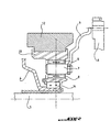
- the rotational coupling means 7, 8 comprise fingers 7 integral with the clutch cover 3 and studs 8 made of a two-part synthetic rubber 81, 82.
- the studs 8 are adhesive on the outer plates 83, 84 in two parts and on an inner frame 85 in one part.
- the fingers 7 constitute supports for the pads 8.
- the fingers 7 are prismatic rods secured to the clutch cover 3 by riveting. They extend from one side of the clutch cover 3, circumferentially spaced therefrom equidistantly. The fingers 7 extend parallel to the crankshaft 5.
- the pads 8 are made of an elastomeric material such as silicone. They comprise a pair of staples 9, preferably two pairs of staples 9, intended to hold the two parts 83, 84 of the outer frame temporarily in a position close to each other for the placement of the pads.
- the two pairs of staples can be mounted parallel or antiparallel.
- FIG. 2 shows the arrangement of the electric machine, in particular of the rotor 12, of the support hub 13, of a bearing 14, for example a ball bearing, as well as the clutch cover 3, a finger 7 and a a stud 8 in detail.
- the pads 8 are respectively embedded in conjugate cavities circumferentially produced equidistantly in the support hub 13.
- the mounting of the pads 8 is carried out as follows.
- the first operation is to install the studs 8 in final position on the fingers 7.
- the second operation consists of preparing the studs, and in particular their outer armature, for the insertion of the studs into the conjugate cavities of the hub 13.
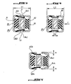
- the two parts 83, 84 of the outer armature are located in the position shown in Figure 3.
- the distance between the two opposite parallel walls of the two parts of the outer frame is at a distance represented by the L1 coast.
- This side L1 corresponds to the width of each of the conjugated cavities formed in the support hub 13.
- the application of a force F in the direction shown in FIG. 4 makes it possible to compress the stud 8 so as to obtain an edge L2 less than the L1 side.
- the L2 coast must be chosen such that the distance s (see Figure 4) between the facing upper ends, referenced 831, 841 and the opposite lower ends, referenced 832, 842, is a set of a few tenths of millimeters. Then, by means of a suitable tool, the staples 9, which are inserted by one of their ends in recesses formed in one or the other of the two parts of the outer frame, are pushed so that the free end engages in a notch provided for this purpose in the other part of the outer frame. By releasing the force F, the rib L2 is made and the staples are held in position by friction such that F divided by 2 and multiplied with a coefficient of friction is greater than the return effect of the staple.
- the third operation is to complete the assembly, that is to say insert the pads 8 in the corresponding conjugate cavities of the support hub 13. Since the L2 side is now lower than the L1 side, the assembly is very easy.
- the fourth operation of the mounting of the pads consists of releasing the pads, that is to say to undo the stapling of the two parts of the outer frame. For this, is applied to the pad 8 a slightly greater effort to F, and that in its direction, developing a torque by the electric motor higher than what it will develop in normal service. Such an operation is generally possible because it is almost instantaneous and therefore of no consequence for the reliability of the electric motor. According to a variant, it is also possible to wait for the first pairs in service and the shocks introduced by the game, shocks which will of course disappear as soon as the elastic function of the pad will be active again.
Landscapes
- Engineering & Computer Science (AREA)
- Mechanical Engineering (AREA)
- Chemical & Material Sciences (AREA)
- Combustion & Propulsion (AREA)
- Transportation (AREA)
- General Engineering & Computer Science (AREA)
- Connection Of Motors, Electrical Generators, Mechanical Devices, And The Like (AREA)
- Mechanical Operated Clutches (AREA)
- Arrangement Of Transmissions (AREA)
- Motor Or Generator Frames (AREA)
Claims (7)
- Kupplungsgehäuse (2) eines Kraftfahrzeugs, wobei das Kupplungsgehäuse (2) einen Kupplungsdeckel (3) aufweist, der mit einem Schwungrad (6) eines Verbrennungsmotors des Kraftfahrzeugs verbunden ist, um rotierend an eine Kurbelwelle (5) des Motors gekoppelt zu sein, eine elektrische Maschine (1), die einen Stator (11), einen Rotor (12) und eine Nabe zum Halten (13) des Rotors (12) aufweist und wobei die Nabe zum Halten (13) des Rotors (12) mit dem Kupplungsdeckel (3) durch rotierende Kupplungsmittel verbunden ist, die Finger (7) umfassen, die mit dem Kupplungsdeckel (3) verbunden sind, und Kontakte (8), die aus einem Gummi bestehen, wobei die Finger (7) Halter für die Kontakte (8) bilden, dadurch gekennzeichnet, dass die Kontakte (8) aus synthetischem Gummi aus zwei Teilen (81, 82) hergestellt werden, mit einer zweiteiligen Außenhülle (83, 84) und einer einteiligen Innenhülle (85).
- Kupplungsgehäuse nach Anspruch 1, dadurch gekennzeichnet, dass die Finger (7) prismatische Stifte sind, die mit dem Kupplungsdeckel (3) durch Nieten oder Schweißen verbunden sind und sich an einer Seite desselben erstrecken, wobei sie umfänglich abstandsgleich voneinander entfernt sind.
- Kupplungsgehäuse nach Anspruch 1 oder 2, dadurch gekennzeichnet, dass sich die Finger (7) parallel zur Kurbelwelle (5) erstrecken.
- Kupplungsgehäuse nach einem der Ansprüche 1 bis 3, dadurch gekennzeichnet, dass die Kontakte (8) aus einem Elastomermaterial wie Silikon hergestellt sind.
- Kupplungsgehäuse nach Anspruch 3, dadurch gekennzeichnet, dass die Kontakte (8) mindestens ein Paar Klammern (9) umfassen, die dazu bestimmt sind, die zwei Teile (83, 84) der Außenhülle zeitlich vorübergehend in einer einander angenäherten Stellung zu halten, um die Kontakte (8) zu platzieren.
- Kupplungsgehäuse nach einem der Ansprüche 1 bis 5, dadurch gekennzeichnet, dass die Kontakte (8) zwei Paar Klammern (9) umfassen, die dazu bestimmt sind, die zwei Teile (83, 84) der Außenhülle zeitlich vorübergehend in einer für die Platzierung der Kontakte (8) einander angenäherten Stellung zu halten, wobei die zwei Paar Klammern anti-parallel montiert sind.
- Kupplungsgehäuse nach einem der Ansprüche 1 bis 5, dadurch gekennzeichnet, dass die Kontakte (8) zwei Paar Klammern (9) umfassen, die dazu bestimmt sind, die zwei Teile (83, 84) der Außenhülle zeitlich vorübergehend in einer für die Platzierung der Kontakte (8) einander angenäherten Stellung zu halten, wobei die zwei Paar Klammern parallel montiert sind.
Applications Claiming Priority (2)
| Application Number | Priority Date | Filing Date | Title |
|---|---|---|---|
| FR0313542A FR2862359B1 (fr) | 2003-11-19 | 2003-11-19 | Dispositif de fixation d'une machine electrique dans un carter d'embrayage d'un vehicule automobile |
| FR0313542 | 2003-11-19 |
Publications (2)
| Publication Number | Publication Date |
|---|---|
| EP1533167A1 EP1533167A1 (de) | 2005-05-25 |
| EP1533167B1 true EP1533167B1 (de) | 2006-12-20 |
Family
ID=34430019
Family Applications (1)
| Application Number | Title | Priority Date | Filing Date |
|---|---|---|---|
| EP04292552A Expired - Lifetime EP1533167B1 (de) | 2003-11-19 | 2004-10-27 | Haltevorrichtung einer elektrischen Maschine in einem Kupplungsgehäuse eines Fahrzeugs |
Country Status (5)
| Country | Link |
|---|---|
| EP (1) | EP1533167B1 (de) |
| AT (1) | ATE348726T1 (de) |
| DE (1) | DE602004003773T2 (de) |
| ES (1) | ES2279315T3 (de) |
| FR (1) | FR2862359B1 (de) |
Families Citing this family (1)
| Publication number | Priority date | Publication date | Assignee | Title |
|---|---|---|---|---|
| DE102008052760A1 (de) | 2008-10-22 | 2010-04-29 | Bayerische Motoren Werke Aktiengesellschaft | Elektrofahrzeug |
Family Cites Families (3)
| Publication number | Priority date | Publication date | Assignee | Title |
|---|---|---|---|---|
| FR2803452B1 (fr) * | 1999-12-29 | 2002-04-05 | Peugeot Citroen Automobiles Sa | Dispositif de fixation d'un equipement electrique, tel qu'un alternateur-demarreur, dans un carter d'embrayage d'un vehicule automobile |
| FR2827925B1 (fr) * | 2001-07-27 | 2003-10-31 | Peugeot Citroen Automobiles Sa | Dispositif d'accouplement elastique entre le rotor d'une machine electrique et l'arbre vilebrequin d'un moteur thermique de vehicule automobile |
| US6781272B2 (en) * | 2002-02-11 | 2004-08-24 | Visteon Global Technologies, Inc. | Integrated torque converter and starter-generator |
-
2003
- 2003-11-19 FR FR0313542A patent/FR2862359B1/fr not_active Expired - Fee Related
-
2004
- 2004-10-27 EP EP04292552A patent/EP1533167B1/de not_active Expired - Lifetime
- 2004-10-27 ES ES04292552T patent/ES2279315T3/es not_active Expired - Lifetime
- 2004-10-27 DE DE602004003773T patent/DE602004003773T2/de not_active Expired - Lifetime
- 2004-10-27 AT AT04292552T patent/ATE348726T1/de not_active IP Right Cessation
Also Published As
| Publication number | Publication date |
|---|---|
| FR2862359B1 (fr) | 2006-02-10 |
| ES2279315T3 (es) | 2007-08-16 |
| DE602004003773T2 (de) | 2007-10-11 |
| FR2862359A1 (fr) | 2005-05-20 |
| DE602004003773D1 (de) | 2007-02-01 |
| EP1533167A1 (de) | 2005-05-25 |
| ATE348726T1 (de) | 2007-01-15 |
Similar Documents
| Publication | Publication Date | Title |
|---|---|---|
| EP0236159B1 (de) | Schwingungsdämpfer für Kraftfahrzeuge | |
| EP2373906B1 (de) | Flexibles schwungrad, insbesondere für ein kraftfahrzeug | |
| EP0237373B1 (de) | Fahrzeug-Schwungrad | |
| WO2013174616A1 (fr) | Dispositif de transmission de couple pour vehicule automobile | |
| FR2988455A1 (fr) | Dispositif de transmission de couple pour un vehicule automobile | |
| EP0341133A1 (de) | Torsionsschwingungsdämpfer mit elastischen Flanschen, insbesondere für Kraftfahrzeuge | |
| EP0730712B1 (de) | Vordämpfungsanlage für rotationsschwingungen | |
| FR2736112A1 (fr) | Ensemble formant disque amortisseur, notamment pour un disque d'embrayage | |
| FR2862359A1 (fr) | Dispositif de fixation d'une machine electrique dans un carter d'embrayage d'un vehicule automobile | |
| FR2798530A1 (fr) | Systeme d'entrainement comprenant un agencement d'amortissement d'oscillations de torsion entre un rotor et un stator | |
| FR2722548A1 (fr) | Embrayage a friction comprenant un volant moteur | |
| EP0200633B1 (de) | Schwingungsdämpfer, insbesondere Kupplungsscheibe für Kraftfahrzeug | |
| FR2902840A1 (fr) | Dispositif de demarrage pour moteur thermique | |
| FR2726341A1 (fr) | Dispositif d'amortissement de torsion | |
| FR3029581A1 (fr) | Dispositif de transmission de couple pour un vehicule automobile | |
| EP0092470A1 (de) | Dämpfungsvorrichtung für Trommelbremse, Bremsankerplatte mit solcher Vorrichtung und Trommelbremse mit Bremsankerplatte versehen mit einer solchen Vorrichtung | |
| FR3064036A1 (fr) | Disque d'embrayage avec rondelle de frottement | |
| EP0732524A1 (de) | Drehschwingungsdämpfer | |
| FR3102223A1 (fr) | Chaîne de transmission pour véhicule hybride ou électrique équipée d’un batteur inertiel à action radiale | |
| FR3004027A1 (fr) | Piece de decouplage entre un moteur et son support, et assemblage d'un moteur sur son support integrant une telle piece de decouplage | |
| FR3075296B1 (fr) | Dispositif d'amortissement pendulaire pour un vehicule automobile | |
| WO2020229632A1 (fr) | Dispositif de transmission de couple équipé d'un moyen de rétention | |
| EP0740747A1 (de) | Vorschaltbare dämpfungseinheit zur dämpfung von rotationsschwingungen | |
| FR2817601A1 (fr) | Double volant amortisseur pour mecanisme d'embrayage de vehicule automobile | |
| EP3734101B1 (de) | Progressive vorrichtung für eine reibungskupplungsscheibe und reibungskupplungsscheibe umfassend eine solche vorrichtung |
Legal Events
| Date | Code | Title | Description |
|---|---|---|---|
| PUAI | Public reference made under article 153(3) epc to a published international application that has entered the european phase |
Free format text: ORIGINAL CODE: 0009012 |
|
| AK | Designated contracting states |
Kind code of ref document: A1 Designated state(s): AT BE BG CH CY CZ DE DK EE ES FI FR GB GR HU IE IT LI LU MC NL PL PT RO SE SI SK TR |
|
| AX | Request for extension of the european patent |
Extension state: AL HR LT LV MK |
|
| 17P | Request for examination filed |
Effective date: 20051026 |
|
| AKX | Designation fees paid |
Designated state(s): AT BE BG CH CY CZ DE DK EE ES FI FR GB GR HU IE IT LI LU MC NL PL PT RO SE SI SK TR |
|
| GRAP | Despatch of communication of intention to grant a patent |
Free format text: ORIGINAL CODE: EPIDOSNIGR1 |
|
| RTI1 | Title (correction) |
Free format text: FIXING DEVICE FOR AN ELECTRIC MACHINE IN A CLUTCH HOUSING OF AN AUTOMOBILE |
|
| GRAS | Grant fee paid |
Free format text: ORIGINAL CODE: EPIDOSNIGR3 |
|
| GRAA | (expected) grant |
Free format text: ORIGINAL CODE: 0009210 |
|
| AK | Designated contracting states |
Kind code of ref document: B1 Designated state(s): AT BE BG CH CY CZ DE DK EE ES FI FR GB GR HU IE IT LI LU MC NL PL PT RO SE SI SK TR |
|
| PG25 | Lapsed in a contracting state [announced via postgrant information from national office to epo] |
Ref country code: NL Free format text: LAPSE BECAUSE OF FAILURE TO SUBMIT A TRANSLATION OF THE DESCRIPTION OR TO PAY THE FEE WITHIN THE PRESCRIBED TIME-LIMIT Effective date: 20061220 Ref country code: PL Free format text: LAPSE BECAUSE OF FAILURE TO SUBMIT A TRANSLATION OF THE DESCRIPTION OR TO PAY THE FEE WITHIN THE PRESCRIBED TIME-LIMIT Effective date: 20061220 Ref country code: RO Free format text: LAPSE BECAUSE OF FAILURE TO SUBMIT A TRANSLATION OF THE DESCRIPTION OR TO PAY THE FEE WITHIN THE PRESCRIBED TIME-LIMIT Effective date: 20061220 Ref country code: FI Free format text: LAPSE BECAUSE OF FAILURE TO SUBMIT A TRANSLATION OF THE DESCRIPTION OR TO PAY THE FEE WITHIN THE PRESCRIBED TIME-LIMIT Effective date: 20061220 Ref country code: SI Free format text: LAPSE BECAUSE OF FAILURE TO SUBMIT A TRANSLATION OF THE DESCRIPTION OR TO PAY THE FEE WITHIN THE PRESCRIBED TIME-LIMIT Effective date: 20061220 Ref country code: DK Free format text: LAPSE BECAUSE OF FAILURE TO SUBMIT A TRANSLATION OF THE DESCRIPTION OR TO PAY THE FEE WITHIN THE PRESCRIBED TIME-LIMIT Effective date: 20061220 Ref country code: SK Free format text: LAPSE BECAUSE OF FAILURE TO SUBMIT A TRANSLATION OF THE DESCRIPTION OR TO PAY THE FEE WITHIN THE PRESCRIBED TIME-LIMIT Effective date: 20061220 Ref country code: AT Free format text: LAPSE BECAUSE OF FAILURE TO SUBMIT A TRANSLATION OF THE DESCRIPTION OR TO PAY THE FEE WITHIN THE PRESCRIBED TIME-LIMIT Effective date: 20061220 Ref country code: IE Free format text: LAPSE BECAUSE OF FAILURE TO SUBMIT A TRANSLATION OF THE DESCRIPTION OR TO PAY THE FEE WITHIN THE PRESCRIBED TIME-LIMIT Effective date: 20061220 Ref country code: CZ Free format text: LAPSE BECAUSE OF FAILURE TO SUBMIT A TRANSLATION OF THE DESCRIPTION OR TO PAY THE FEE WITHIN THE PRESCRIBED TIME-LIMIT Effective date: 20061220 |
|
| REG | Reference to a national code |
Ref country code: GB Ref legal event code: FG4D Free format text: NOT ENGLISH |
|
| REG | Reference to a national code |
Ref country code: CH Ref legal event code: EP |
|
| REF | Corresponds to: |
Ref document number: 602004003773 Country of ref document: DE Date of ref document: 20070201 Kind code of ref document: P |
|
| REG | Reference to a national code |
Ref country code: IE Ref legal event code: FG4D Free format text: LANGUAGE OF EP DOCUMENT: FRENCH |
|
| PG25 | Lapsed in a contracting state [announced via postgrant information from national office to epo] |
Ref country code: SE Free format text: LAPSE BECAUSE OF FAILURE TO SUBMIT A TRANSLATION OF THE DESCRIPTION OR TO PAY THE FEE WITHIN THE PRESCRIBED TIME-LIMIT Effective date: 20070320 Ref country code: BG Free format text: LAPSE BECAUSE OF FAILURE TO SUBMIT A TRANSLATION OF THE DESCRIPTION OR TO PAY THE FEE WITHIN THE PRESCRIBED TIME-LIMIT Effective date: 20070320 |
|
| GBT | Gb: translation of ep patent filed (gb section 77(6)(a)/1977) |
Effective date: 20070307 |
|
| PG25 | Lapsed in a contracting state [announced via postgrant information from national office to epo] |
Ref country code: PT Free format text: LAPSE BECAUSE OF FAILURE TO SUBMIT A TRANSLATION OF THE DESCRIPTION OR TO PAY THE FEE WITHIN THE PRESCRIBED TIME-LIMIT Effective date: 20070424 |
|
| NLV1 | Nl: lapsed or annulled due to failure to fulfill the requirements of art. 29p and 29m of the patents act | ||
| REG | Reference to a national code |
Ref country code: ES Ref legal event code: FG2A Ref document number: 2279315 Country of ref document: ES Kind code of ref document: T3 |
|
| PLBE | No opposition filed within time limit |
Free format text: ORIGINAL CODE: 0009261 |
|
| STAA | Information on the status of an ep patent application or granted ep patent |
Free format text: STATUS: NO OPPOSITION FILED WITHIN TIME LIMIT |
|
| 26N | No opposition filed |
Effective date: 20070921 |
|
| REG | Reference to a national code |
Ref country code: GB Ref legal event code: 746 Effective date: 20080329 |
|
| BERE | Be: lapsed |
Owner name: PEUGEOT CITROEN AUTOMOBILES S.A. Effective date: 20071031 |
|
| PG25 | Lapsed in a contracting state [announced via postgrant information from national office to epo] |
Ref country code: GR Free format text: LAPSE BECAUSE OF FAILURE TO SUBMIT A TRANSLATION OF THE DESCRIPTION OR TO PAY THE FEE WITHIN THE PRESCRIBED TIME-LIMIT Effective date: 20070321 |
|
| PG25 | Lapsed in a contracting state [announced via postgrant information from national office to epo] |
Ref country code: MC Free format text: LAPSE BECAUSE OF NON-PAYMENT OF DUE FEES Effective date: 20071031 |
|
| PG25 | Lapsed in a contracting state [announced via postgrant information from national office to epo] |
Ref country code: BE Free format text: LAPSE BECAUSE OF NON-PAYMENT OF DUE FEES Effective date: 20071031 |
|
| PG25 | Lapsed in a contracting state [announced via postgrant information from national office to epo] |
Ref country code: EE Free format text: LAPSE BECAUSE OF FAILURE TO SUBMIT A TRANSLATION OF THE DESCRIPTION OR TO PAY THE FEE WITHIN THE PRESCRIBED TIME-LIMIT Effective date: 20061220 |
|
| REG | Reference to a national code |
Ref country code: CH Ref legal event code: PL |
|
| PG25 | Lapsed in a contracting state [announced via postgrant information from national office to epo] |
Ref country code: LU Free format text: LAPSE BECAUSE OF NON-PAYMENT OF DUE FEES Effective date: 20071027 Ref country code: CY Free format text: LAPSE BECAUSE OF FAILURE TO SUBMIT A TRANSLATION OF THE DESCRIPTION OR TO PAY THE FEE WITHIN THE PRESCRIBED TIME-LIMIT Effective date: 20061220 |
|
| PG25 | Lapsed in a contracting state [announced via postgrant information from national office to epo] |
Ref country code: HU Free format text: LAPSE BECAUSE OF FAILURE TO SUBMIT A TRANSLATION OF THE DESCRIPTION OR TO PAY THE FEE WITHIN THE PRESCRIBED TIME-LIMIT Effective date: 20070621 Ref country code: TR Free format text: LAPSE BECAUSE OF FAILURE TO SUBMIT A TRANSLATION OF THE DESCRIPTION OR TO PAY THE FEE WITHIN THE PRESCRIBED TIME-LIMIT Effective date: 20061220 |
|
| PG25 | Lapsed in a contracting state [announced via postgrant information from national office to epo] |
Ref country code: LI Free format text: LAPSE BECAUSE OF NON-PAYMENT OF DUE FEES Effective date: 20081031 Ref country code: CH Free format text: LAPSE BECAUSE OF NON-PAYMENT OF DUE FEES Effective date: 20081031 |
|
| REG | Reference to a national code |
Ref country code: ES Ref legal event code: GC2A Effective date: 20110406 |
|
| PGFP | Annual fee paid to national office [announced via postgrant information from national office to epo] |
Ref country code: GB Payment date: 20120924 Year of fee payment: 9 |
|
| PGFP | Annual fee paid to national office [announced via postgrant information from national office to epo] |
Ref country code: IT Payment date: 20120924 Year of fee payment: 9 |
|
| PGFP | Annual fee paid to national office [announced via postgrant information from national office to epo] |
Ref country code: DE Payment date: 20120924 Year of fee payment: 9 Ref country code: FR Payment date: 20121115 Year of fee payment: 9 |
|
| PGFP | Annual fee paid to national office [announced via postgrant information from national office to epo] |
Ref country code: ES Payment date: 20120920 Year of fee payment: 9 |
|
| REG | Reference to a national code |
Ref country code: DE Ref legal event code: R119 Ref document number: 602004003773 Country of ref document: DE |
|
| GBPC | Gb: european patent ceased through non-payment of renewal fee |
Effective date: 20131027 |
|
| REG | Reference to a national code |
Ref country code: DE Ref legal event code: R079 Ref document number: 602004003773 Country of ref document: DE Free format text: PREVIOUS MAIN CLASS: B60K0006040000 Ipc: B60K0006000000 |
|
| PG25 | Lapsed in a contracting state [announced via postgrant information from national office to epo] |
Ref country code: GB Free format text: LAPSE BECAUSE OF NON-PAYMENT OF DUE FEES Effective date: 20131027 |
|
| REG | Reference to a national code |
Ref country code: DE Ref legal event code: R079 Ref document number: 602004003773 Country of ref document: DE Free format text: PREVIOUS MAIN CLASS: B60K0006040000 Ipc: B60K0006000000 Effective date: 20140625 Ref country code: DE Ref legal event code: R119 Ref document number: 602004003773 Country of ref document: DE Effective date: 20140501 |
|
| REG | Reference to a national code |
Ref country code: FR Ref legal event code: ST Effective date: 20140630 |
|
| PG25 | Lapsed in a contracting state [announced via postgrant information from national office to epo] |
Ref country code: IT Free format text: LAPSE BECAUSE OF NON-PAYMENT OF DUE FEES Effective date: 20131027 Ref country code: DE Free format text: LAPSE BECAUSE OF NON-PAYMENT OF DUE FEES Effective date: 20140501 Ref country code: FR Free format text: LAPSE BECAUSE OF NON-PAYMENT OF DUE FEES Effective date: 20131031 |
|
| REG | Reference to a national code |
Ref country code: ES Ref legal event code: FD2A Effective date: 20141107 |
|
| PG25 | Lapsed in a contracting state [announced via postgrant information from national office to epo] |
Ref country code: ES Free format text: LAPSE BECAUSE OF NON-PAYMENT OF DUE FEES Effective date: 20131028 |