EP1533153B1 - Verstellbare Luftleiteinrichtung, insbesondere fur einen Luftverteiler einer Fahrzeugklimaanlage - Google Patents
Verstellbare Luftleiteinrichtung, insbesondere fur einen Luftverteiler einer Fahrzeugklimaanlage Download PDFInfo
- Publication number
- EP1533153B1 EP1533153B1 EP03292912A EP03292912A EP1533153B1 EP 1533153 B1 EP1533153 B1 EP 1533153B1 EP 03292912 A EP03292912 A EP 03292912A EP 03292912 A EP03292912 A EP 03292912A EP 1533153 B1 EP1533153 B1 EP 1533153B1
- Authority
- EP
- European Patent Office
- Prior art keywords
- air
- damper
- duct
- flap
- pivot axis
- Prior art date
- Legal status (The legal status is an assumption and is not a legal conclusion. Google has not performed a legal analysis and makes no representation as to the accuracy of the status listed.)
- Expired - Lifetime
Links
Images


Classifications
-
- B—PERFORMING OPERATIONS; TRANSPORTING
- B60—VEHICLES IN GENERAL
- B60H—ARRANGEMENTS OF HEATING, COOLING, VENTILATING OR OTHER AIR-TREATING DEVICES SPECIALLY ADAPTED FOR PASSENGER OR GOODS SPACES OF VEHICLES
- B60H1/00—Heating, cooling or ventilating devices
- B60H1/00642—Control systems or circuits; Control members or indication devices for heating, cooling or ventilating devices
- B60H1/00664—Construction or arrangement of damper doors
- B60H1/00671—Damper doors moved by rotation; Grilles
- B60H1/00685—Damper doors moved by rotation; Grilles the door being a rotating disc or cylinder or part thereof
Definitions
- the present invention relates to an adjustable air guiding device, in particular for an air distributor of a vehicle air conditioning system with the features of the preamble of patent claim 1.
- Vehicle air conditioning systems usually have an air duct with a heat exchanger arranged therein and a heating device arranged downstream of it.
- An adjustable air guide is used for warm air control.
- the cooled air exiting the heat exchanger may be variably distributed between a branch passage having the heater arranged therein and a bypass passage parallel to this branch passage.
- the temperature of the outflowing air is regulated.
- Gutleit- or adjusting a number of flap systems are known, for example drum flaps with a perpendicular to the longitudinal direction of the air duct arranged pivot axis. Also, different sliding or rolling flaps are known.
- the known adjustment systems have a mounting size and a space requirement, which leads to a relatively large distance between the heat exchanger and the heater.
- the entire construction volume of the air conditioner increases thereby.
- An object of the present invention is to provide an adjustable air guide for an air duct, which has a small footprint and good controllability.
- An adjustable air guiding device which is particularly suitable for an air distributor of a vehicle air conditioning system, comprises a pivotable flat flap arranged within an air duct for at least partially blocking or opening a partial cross section of the air duct.
- a pivot axis of the flap is arranged approximately parallel to the longitudinal direction of the air duct.
- the pivot axis is arranged approximately centrally in the channel cross section.
- a surface of the flat flap is preferably parallel to a vertical channel cross-section arranged.
- the flap has an approximately semicircular contour, which is preferably adapted to a contour of the air duct. Your straight base side is attached approximately in the middle of the pivot axis.
- the flap can also have a plurality of segments, which are arranged regularly one after the other so that the different airways can be blocked or released when the flap is pivoted.
- the flap between a heat exchanger and a heater of the vehicle air conditioning these can be arranged at a very small distance from each other, since the flap requires only a minimal installation space due to its flat design.
- the flap closes a branch channel of the air duct with the heating device arranged therein and leaves open a branch channel parallel to the bypass channel.
- the flap closes the bypass channel and leaves the branch channel open.
- the temperature of the cooled air coming from the heat exchanger can be regulated by a variable opening of the channel cross section.
- the pivot axis can be rotated in particular by means of an electric servomotor, for example by means of a stepper motor.
- a gear between the servomotor and the pivot axis may be provided.
- FIG. 1 illustrates in a schematic sectional view of an air distributor 10 of a vehicle air conditioning system, in the air duct 12, a heat exchanger 14 is arranged for cooling by means of a ventilation device 16 conveyed air. Downstream of the heat exchanger 14, a heater 18 is provided, which is arranged in a branch channel 20. Parallel to the branch channel runs a bypass channel 22, which serves the cold air duct. Branch channel 20 and bypass channel 22 are further merged downstream again to the common air duct 12.
- the air conveyed herein is conveyed to various exhaust ports (not shown) in the vehicle interior, for example, in a footwell, a middle region of the interior, and a disk-near region.
- an adjustable air guide device in the form of a flap 24 is arranged, which can be pivoted about a pivot axis 26 and selectively closes a part of the branch channel 20 and the bypass channel 22 opens or vice versa. It can be clearly seen that the heat exchanger 14 and the heater 18 are arranged at a very small distance from each other, so that very compact air distributor and air conditioning systems can be built.
- the flap 24 has a semicircular contour, as illustrated by the following figures.
- the pivot axis 26 is arranged at the level of the flap 24 approximately parallel to a longitudinal extension direction of the air duct 12 and is preferably located in a region between the branch channel 20 and the bypass channel 22.
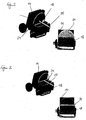
- FIGS. 2 and 3 illustrate the different positions of the pivotable flap 24th FIG. 2 illustrates in two views a first stop position of the louver, in which the semicircular flap 24 largely closes the bypass channel 22, so that the conditioned air must flow largely through the branch channel 20 with the heater 18 disposed therein.
- bypass channel 22 In any intermediate position, a part of the bypass channel 22 is opened and a part of the branch channel 20 also open, so that in this way a temperature regulation of the cooled air is made possible.
- FIG. 4 illustrates in two views the contour and arrangement of the semicircular flap 24, which can be pivoted by means of the pivot axis 26.
- the top view of the left side illustrates the semicircular contour of the flap 24, while the sectional view along the section line AA of the right side illustrates the arrangement of the pivot axis 26 and the connection of the flap 24 with the free end of the pivot axis 26.
- the spoiler device according to the invention thus functions in the manner of a diaphragm which more or less releases or closes the bypass duct 22 and the branch duct 20, depending on the angular position.
Landscapes
- Physics & Mathematics (AREA)
- Thermal Sciences (AREA)
- Engineering & Computer Science (AREA)
- Mechanical Engineering (AREA)
- Air-Flow Control Members (AREA)
- Air-Conditioning For Vehicles (AREA)
Description
- Die vorliegende Erfindung betrifft eine verstellbare Luftleiteinrichtung, insbesondere für einen Luftverteiler einer Fahrzeugklimaanlage mit den Merkmalen des Oberbegriffs des Patentanspruchs 1.
- Fahrzeugklimaanlagen weisen üblicherweise einen Luftführungskanal mit darin angeordnetem Wärmetauscher und einer diesem nachgeordneten Heizeinrichtung auf. Eine verstellbare Luftleiteinrichtung dient zur Warmluftsteuerung. Die aus dem Wärmetauscher austretende gekühlte Luft kann variabel zwischen einem Zweigkanal mit der darin angeordneten Heizeinrichtung und einem zu diesem Zweigkanal parallelen Bypasskanal verteilt werden. Je nach der Menge der durch den Zweigkanal beziehungsweise durch den Bypasskanal strömenden Luft wird die Temperatur der ausströmenden Luft reguliert. Als derartige Luftleit- bzw. Verstelleinrichtungen sind eine Reihe von Klappensystemen bekannt, beispielsweise Trommelklappen mit einer senkrecht zur Längsrichtung des Luftführungskanals angeordneten Schwenkachse. Auch unterschiedliche Verschiebe oder Rollklappen sind bekannt.
- Die bekannten Verstellsysteme weisen eine Einbaugröße und einen Platzbedarf auf, der zu einem relativ großen Abstand zwischen Wärmetauscher und Heizeinrichtung führt. Das gesamte Bauvolumen der Klimaanlage nimmt dadurch zu.
- Aus der
US 5,070,770 ist eine Heizungs- und Klimaanlage mit einer verstellbaren Klappe zwischen Verdampfer und Heizkörper bekannt, die eine kreisförmige Kontur aufweist. - Eine Aufgabe der vorliegenden Erfindung besteht darin, eine verstellbare Luftleiteinrichtung für einen Luftführungskanal zur Verfügung zu stellen, die einen geringen Platzbedarf und eine gute Steuerbarkeit aufweist.
- Diese Aufgabe wird mit dem Gegenstand des unabhängigen Patentanspruchs gelöst. Merkmale vorteilhafter Weiterbildungen ergeben sich aus abhängigen Ansprüchen.
- Eine verstellbare Luftleiteinrichtung, die insbesondere für einen Luftverteiler einer Fahrzeugklimaanlage geeignet ist, umfasst eine innerhalb eines Luftführungskanals angeordnete schwenkbare flache Klappe zum zumindest teilweisen Versperren oder Öffnen eines Teilquerschnitts der Luftführungskanals. Erfindungsgemäß ist eine Schwenkachse der Klappe in etwa parallel zur Längserstreckungsrichtung des Luftführungskanals angeordnet. Die Schwenkachse ist ungefähr mittig im Kanalquerschnitt angeordnet. Eine Oberfläche der flachen Klappe ist vorzugsweise parallel zu einem senkrechten Kanalquerschnitt angeordnet. Die Klappe weist eine in etwa halbkreisförmige Kontur auf, die vorzugsweise an eine Kontur des Luftführungskanals angepasst ist. Ihre gerade Basisseite ist ungefähr mittig an der Schwenkachse befestigt. Gegebenenfalls kann die Klappe auch mehrere Segmente aufweisen, die regelmäßig aufeinander folgend angeordnet sind, so dass bei einem Verschwenken der Klappe die unterschiedlichen Luftwege versperrt oder freigegeben werden können.
- Bei einer Anordnung der Klappe zwischen einem Wärmetauscher und einer Heizeinrichtung der Fahrzeugklimaanlage können diese in sehr geringem Abstand zueinander angeordnet sein, da die Klappe aufgrund ihrer flachen Bauweise nur einen minimalen Einbauraum benötigt. In einer ersten Anschlagstellung verschließt die Klappe einen Zweigkanal des Luftführungskanals mit der darin angeordneten Heizeinrichtung und lässt einen zum Zweigkanal parallelen Bypasskanal offen. In einer zweiten Anschlagstellung verschließt die Klappe den Bypasskanal und lässt den Zweigkanal offen. In einer beliebigen Zwischenstellung kann die Temperatur der aus dem Wärmetauscher kommenden gekühlten Luft durch eine variable Öffnung des Kanalquerschnitts reguliert werden.
- Die Schwenkachse kann insbesondere mittels eines elektrischen Stellmotors verdrehbar sein, beispielsweise mittels eines Schrittmotors. Gegebenenfalls kann auch ein Getriebe zwischen dem Stellmotor und der Schwenkachse vorgesehen sein.
- Die Erfindung wird nachfolgend anhand eines bevorzugten Ausführungsbeispielen unter Bezugnahme auf die beiliegenden Figuren näher erläutert. Dabei zeigt:
- Figur 1
- einen schematischen Querschnitt eines Luftverteilers einer Fahrzeugklimaanlage mit einer darin angeordneten verstellbaren Luftleiteinrichtung.
- Figur 2
- eine Prinzipdarstellung einer Klappenanordnung der Luftleiteinrichtung in einer ersten Anschlagstellung der Klappe,
- Figur 3
- eine Prinzipdarstellung entsprechend
Figur 2 in einer zweiten Anschlagstellung der Klappe und - Figur 4
- zwei schematische Ansichten der Klappe.
-
Figur 1 verdeutlicht in einer schematischen Schnittdarstellung einen Luftverteiler 10 einer Fahrzeugklimaanlage, in dessen Luftführungskanal 12 ein Wärmetauscher 14 zum Abkühlen von mittels einer Ventilationseinrichtung 16 geförderten Luft angeordnet ist. Stromabwärts des Wärmetauschers 14 ist eine Heizeinrichtung 18 vorgesehen, die in einem Zweigkanal 20 angeordnet ist. Parallel zum Zweigkanal verläuft ein Bypasskanal 22, der der Kaltluftführung dient. Zweigkanal 20 und Bypasskanal 22 werden weiter stromabwärts wieder zum gemeinsamen Luftführungskanal 12 zusammengeführt. Die hierin geförderte Luft wird zu verschiedenen Ausströmöffnungen (nicht dargestellt) im Fahrzeuginnenraum gefördert, beispielsweise in einem Fußraum, einen mittleren Bereich des Innenraums sowie einen scheibennahen Bereich. - Zwischen Heizeinrichtung 18 und Wärmetauscher 14 ist eine erfindungsgemäße verstellbaren Luftleiteinrichtung in Form einer Klappe 24 angeordnet, die um eine Schwenkachse 26 verschwenkt werden kann und wahlweise einen Teil des Zweigkanals 20 verschließt und des Bypasskanals 22 öffnet beziehungsweise umgekehrt. Es ist hierbei deutlich erkennbar, dass der Wärmetauscher 14 und die Heizeinrichtung 18 in sehr geringem Abstand zueinander angeordnet sind, so dass sehr kompakte Luftverteiler und Klimaanlagen aufgebaut werden können.
- Die Klappe 24 weist eine halbkreisförmige Kontur auf, wie anhand der folgenden Figuren verdeutlicht wird. Die Schwenkachse 26 ist auf Höhe der Klappe 24 in etwa parallel zu einer Längserstreckungsrichtung des Luftführungskanals 12 angeordnet und befindet sich vorzugsweise in einem Bereich zwischen Zweigkanal 20 und Bypasskanal 22.
- Die
Figuren 2 und 3 verdeutlichen die unterschiedlichen Stellungen der verschwenkbaren Klappe 24.Figur 2 illustriert in zwei Ansichten eine erste Anschlagstellung der Luftleiteinrichtung, bei der die halbkreisförmige Klappe 24 den Bypasskanal 22 weitgehend verschließt, so dass die klimatisierte Luft weitgehend durch den Zweigkanal 20 mit der darin angeordneten Heizeinrichtung 18 strömen muss. - Durch Verdrehen der Schwenkachse 26 um einen Winkel von 180 Grad wird eine zweite Anschlagstellung erreicht, welche anhand der
Figur 3 verdeutlicht ist. Hierbei ist der Zweigkanal 20 unmittelbar vor der Heizeinrichtung 18 versperrt und gleichzeitig der Bypasskanal 22 freigegeben, so dass weitgehend die gesamte Luftströmung durch den Bypasskanal 22 verläuft. - In einer beliebigen Zwischenstellung ist ein Teil des Bypasskanals 22 geöffnet und ein Teil des Zweigkanals 20 ebenfalls offen, so dass auf diese Weise eine Temperaturregulierung der gekühlten Luft ermöglicht ist.
-
Figur 4 verdeutlicht in zwei Ansichten die Kontur und Anordnung der halbkreisförmigen Klappe 24, die mittels der Schwenkachse 26 verschwenkt werden kann. Die Draufsicht der linken Seite verdeutlicht die halbkreisförmige Kontur der Klappe 24, während die Schnittdarstellung entlang der Schnittlinie A-A der rechten Seite die Anordnung der Schwenkachse 26 und die Verbindung der Klappe 24 mit dem freien Ende der Schwenkachse 26 verdeutlicht. - Die erfindungsgemäße Luftleiteinrichtung funktioniert somit in Art einer Blende, welche den Bypasskanal 22 und den Zweigkanal 20 je nach Winkelstellung mehr oder weniger freigibt bzw. verschließt.
Claims (6)
- Verstellbare Luftleiteinrichtung, mit einem Luftführungskanal (12), Wärmetauscher (14) und Heizeinrichtung (18), für einen Luftverteiler einer Fahrzeugklimaanlage, mit einer innerhalb des Luftführungskanals (12) angeordneten schwenkbaren flachen Klappe (24) zum zumindest teilweisen Versperren oder Öffnen eines Teilquerschnitts des Luftführungskanals (12), wobei die Klappe (24) eine in etwa halbkreisförmige Kontur hat, an deren gerader Basisseite der Klappe (24) ungefähr mittig die Schwenkachse (26) befestigt ist, wobei die Klappe zwischen einem Wärmetauscher (14) und einer Heizeinrichtung (18) der Fahrzeugklimaanlage angeordnet ist und die Schwenkachse (26) in etwa parallel zur Längserstreckungsrichtung des Luftführungskanals (12) ist, dadurch gekennzeichnet, dass eine Oberfläche der flachen Klappe (24) parallel zu einem senkrechten Kanalquerschnitt und in etwa parallel zum Wärmetauscher (14) und zur Heizeinrichtung (18) angeordnet ist.
- Luftleiteinrichtung nach Anspruch 1, dadurch gekennzeichnet, dass die Schwenkachse (26) ungefähr mittig im Kanalquerschnitt angeordnet ist.
- Luftleiteinrichtung nach einem der voranstehenden Ansprüche, dadurch gekennzeichnet, dass die Klappe (24) wenigstens zwei Segmente aufweist, die gegenüber liegend angeordnet sind.
- Luftleiteinrichtung nach einem der voranstehenden Ansprüche, dadurch gekennzeichnet, dass die Klappe (24) in einer ersten Anschlagstellung einen Zweigkanal (20) des Luftführungskanal (12) mit der darin angeordneten Heizeinrichtung (18) verschließt und einen zum Zweigkanal (20) parallelen Bypasskanal (22) offen lässt.
- Luftleiteinrichtung nach einem der voranstehenden Ansprüche, dadurch gekennzeichnet, dass die Klappe (24) in einer zweiten Anschlagstellung den Bypasskanal (22) verschließt und den Zweigkanal (20) offen lässt.
- Luftleiteinrichtung nach einem der voranstehenden Ansprüche, dadurch gekennzeichnet, dass die Schwenkachse (26) mittels eines elektrischen Stellmotors verdrehbar ist.
Priority Applications (3)
| Application Number | Priority Date | Filing Date | Title |
|---|---|---|---|
| AT03292912T ATE407817T1 (de) | 2003-11-21 | 2003-11-21 | Verstellbare luftleiteinrichtung, insbesondere fur einen luftverteiler einer fahrzeugklimaanlage |
| EP03292912A EP1533153B1 (de) | 2003-11-21 | 2003-11-21 | Verstellbare Luftleiteinrichtung, insbesondere fur einen Luftverteiler einer Fahrzeugklimaanlage |
| DE50310479T DE50310479D1 (de) | 2003-11-21 | 2003-11-21 | Verstellbare Luftleiteinrichtung, insbesondere fur einen Luftverteiler einer Fahrzeugklimaanlage |
Applications Claiming Priority (1)
| Application Number | Priority Date | Filing Date | Title |
|---|---|---|---|
| EP03292912A EP1533153B1 (de) | 2003-11-21 | 2003-11-21 | Verstellbare Luftleiteinrichtung, insbesondere fur einen Luftverteiler einer Fahrzeugklimaanlage |
Publications (2)
| Publication Number | Publication Date |
|---|---|
| EP1533153A1 EP1533153A1 (de) | 2005-05-25 |
| EP1533153B1 true EP1533153B1 (de) | 2008-09-10 |
Family
ID=34429581
Family Applications (1)
| Application Number | Title | Priority Date | Filing Date |
|---|---|---|---|
| EP03292912A Expired - Lifetime EP1533153B1 (de) | 2003-11-21 | 2003-11-21 | Verstellbare Luftleiteinrichtung, insbesondere fur einen Luftverteiler einer Fahrzeugklimaanlage |
Country Status (3)
| Country | Link |
|---|---|
| EP (1) | EP1533153B1 (de) |
| AT (1) | ATE407817T1 (de) |
| DE (1) | DE50310479D1 (de) |
Families Citing this family (1)
| Publication number | Priority date | Publication date | Assignee | Title |
|---|---|---|---|---|
| DE102004054838A1 (de) * | 2004-11-12 | 2006-05-24 | Behr Gmbh & Co. Kg | Steuerorgan |
Citations (1)
| Publication number | Priority date | Publication date | Assignee | Title |
|---|---|---|---|---|
| US4216822A (en) * | 1977-05-20 | 1980-08-12 | Nissan Motor Company, Limited | Airflow distributing device for automotive air-conditioning system |
Family Cites Families (2)
| Publication number | Priority date | Publication date | Assignee | Title |
|---|---|---|---|---|
| US5070770A (en) * | 1990-05-23 | 1991-12-10 | General Motors Corporation | Simultaneous temperature and mode selector for heating and cooling |
| DE10204735A1 (de) * | 2002-02-06 | 2003-08-14 | Behr Gmbh & Co | Luftmischvorrichtung für eine Fahrzeugklimatisierungseinrichtung |
-
2003
- 2003-11-21 AT AT03292912T patent/ATE407817T1/de not_active IP Right Cessation
- 2003-11-21 EP EP03292912A patent/EP1533153B1/de not_active Expired - Lifetime
- 2003-11-21 DE DE50310479T patent/DE50310479D1/de not_active Expired - Fee Related
Patent Citations (1)
| Publication number | Priority date | Publication date | Assignee | Title |
|---|---|---|---|---|
| US4216822A (en) * | 1977-05-20 | 1980-08-12 | Nissan Motor Company, Limited | Airflow distributing device for automotive air-conditioning system |
Also Published As
| Publication number | Publication date |
|---|---|
| DE50310479D1 (de) | 2008-10-23 |
| EP1533153A1 (de) | 2005-05-25 |
| ATE407817T1 (de) | 2008-09-15 |
Similar Documents
| Publication | Publication Date | Title |
|---|---|---|
| EP1902876B1 (de) | Luftführungsgehäuse, insbesondere für eine Kraftfahrzeug-Klimaanlage, mit einer Verteilerklappe und Verfahren zur Regelung einer derartigen Verteilerklappe | |
| DE60223437T2 (de) | Fahrzeugklimaanlage | |
| EP0770508A2 (de) | Klimaanlage für ein Kraftfahrzeug | |
| DE19922324C1 (de) | Heizungs- oder Klimaanlage für eine Fahrgastzelle eines Fahrzeugs | |
| DE102015110481A1 (de) | Vorrichtung zum Beheizen, Belüften und/oder Klimatisieren eines Fahrzeuginnenraums | |
| DE19919975C1 (de) | Klimaanlage für eine Fahrgastzelle eines Fahrzeugs | |
| DE10025334A1 (de) | Luftverteiler einer Heiz-, Lüftungs- und/oder Klimaanlage | |
| DE202018104942U1 (de) | Luftausströmer | |
| EP1673246A1 (de) | Bauteil für eine vorrichtung zur klimatisierung eines fahrzeuginnenraums und vorrichtung zur klimatisierung eines fahrzeuginnenraums | |
| DE60029836T2 (de) | Heizungs- und Klimaanlage mit einer Luftmischklappe | |
| DE102007013432B4 (de) | Warmluftkanal für ein Klimagerät eines Kraftfahrzeuges | |
| DE102014209452B4 (de) | Klimaanlage mit Bypassvorrichtung und Verfahren | |
| EP1930191A1 (de) | Fahrzeugheizungs- und/oder Klimaanlage mit kombinierter Luftmisch- und -verteilerklappe | |
| DE19854795C1 (de) | Belüftungsvorrichtung für Fahrzeuge | |
| DE3510991A1 (de) | Vorrichtung zum beheizen und/oder klimatisieren eines kraftfahrzeuginnenraums | |
| EP1533153B1 (de) | Verstellbare Luftleiteinrichtung, insbesondere fur einen Luftverteiler einer Fahrzeugklimaanlage | |
| EP0841202B1 (de) | Heiz- oder Klimaanlage | |
| DE2757651A1 (de) | Heiz- und belueftungsvorrichtung | |
| EP3560738B1 (de) | Luftausströmer | |
| EP2174809A1 (de) | Fahrzeugklimaanlage | |
| EP1522434B1 (de) | Klimaanlage, insbesondere Kraftfahrzeug-Klimaanlage | |
| EP1319537B1 (de) | Heiz- oder Klimaanlage für ein Kraftfahrzeug | |
| EP1571019B1 (de) | Klimatisierungsvorrichtung, insbesondere für ein Krafffahrzeug | |
| EP2050598B1 (de) | Klappenanordnung, für eine Fahrzeug-Klimaanlage | |
| EP1738941A1 (de) | Kraftfahrzeug-Klimaanlage |
Legal Events
| Date | Code | Title | Description |
|---|---|---|---|
| PUAI | Public reference made under article 153(3) epc to a published international application that has entered the european phase |
Free format text: ORIGINAL CODE: 0009012 |
|
| AK | Designated contracting states |
Kind code of ref document: A1 Designated state(s): AT BE BG CH CY CZ DE DK EE ES FI FR GB GR HU IE IT LI LU MC NL PT RO SE SI SK TR |
|
| AX | Request for extension of the european patent |
Extension state: AL LT LV MK |
|
| RAP1 | Party data changed (applicant data changed or rights of an application transferred) |
Owner name: BEHR FRANCE ROUFFACH SAS |
|
| 17P | Request for examination filed |
Effective date: 20051125 |
|
| AKX | Designation fees paid |
Designated state(s): AT BE BG CH CY CZ DE DK EE ES FI FR GB GR HU IE IT LI LU MC NL PT RO SE SI SK TR |
|
| 17Q | First examination report despatched |
Effective date: 20060131 |
|
| 17Q | First examination report despatched |
Effective date: 20060131 |
|
| GRAP | Despatch of communication of intention to grant a patent |
Free format text: ORIGINAL CODE: EPIDOSNIGR1 |
|
| GRAS | Grant fee paid |
Free format text: ORIGINAL CODE: EPIDOSNIGR3 |
|
| GRAA | (expected) grant |
Free format text: ORIGINAL CODE: 0009210 |
|
| AK | Designated contracting states |
Kind code of ref document: B1 Designated state(s): AT BE BG CH CY CZ DE DK EE ES FI FR GB GR HU IE IT LI LU MC NL PT RO SE SI SK TR |
|
| REG | Reference to a national code |
Ref country code: GB Ref legal event code: FG4D Free format text: NOT ENGLISH |
|
| REG | Reference to a national code |
Ref country code: CH Ref legal event code: EP |
|
| REG | Reference to a national code |
Ref country code: IE Ref legal event code: FG4D Free format text: LANGUAGE OF EP DOCUMENT: GERMAN |
|
| REF | Corresponds to: |
Ref document number: 50310479 Country of ref document: DE Date of ref document: 20081023 Kind code of ref document: P |
|
| PGFP | Annual fee paid to national office [announced via postgrant information from national office to epo] |
Ref country code: DE Payment date: 20081201 Year of fee payment: 6 |
|
| PG25 | Lapsed in a contracting state [announced via postgrant information from national office to epo] |
Ref country code: SI Free format text: LAPSE BECAUSE OF FAILURE TO SUBMIT A TRANSLATION OF THE DESCRIPTION OR TO PAY THE FEE WITHIN THE PRESCRIBED TIME-LIMIT Effective date: 20080910 Ref country code: FI Free format text: LAPSE BECAUSE OF FAILURE TO SUBMIT A TRANSLATION OF THE DESCRIPTION OR TO PAY THE FEE WITHIN THE PRESCRIBED TIME-LIMIT Effective date: 20080910 |
|
| NLV1 | Nl: lapsed or annulled due to failure to fulfill the requirements of art. 29p and 29m of the patents act | ||
| REG | Reference to a national code |
Ref country code: IE Ref legal event code: FD4D |
|
| PG25 | Lapsed in a contracting state [announced via postgrant information from national office to epo] |
Ref country code: BG Free format text: LAPSE BECAUSE OF FAILURE TO SUBMIT A TRANSLATION OF THE DESCRIPTION OR TO PAY THE FEE WITHIN THE PRESCRIBED TIME-LIMIT Effective date: 20081210 Ref country code: IE Free format text: LAPSE BECAUSE OF FAILURE TO SUBMIT A TRANSLATION OF THE DESCRIPTION OR TO PAY THE FEE WITHIN THE PRESCRIBED TIME-LIMIT Effective date: 20080910 Ref country code: ES Free format text: LAPSE BECAUSE OF FAILURE TO SUBMIT A TRANSLATION OF THE DESCRIPTION OR TO PAY THE FEE WITHIN THE PRESCRIBED TIME-LIMIT Effective date: 20081221 |
|
| PGFP | Annual fee paid to national office [announced via postgrant information from national office to epo] |
Ref country code: FR Payment date: 20081127 Year of fee payment: 6 |
|
| PG25 | Lapsed in a contracting state [announced via postgrant information from national office to epo] |
Ref country code: NL Free format text: LAPSE BECAUSE OF FAILURE TO SUBMIT A TRANSLATION OF THE DESCRIPTION OR TO PAY THE FEE WITHIN THE PRESCRIBED TIME-LIMIT Effective date: 20080910 Ref country code: CZ Free format text: LAPSE BECAUSE OF FAILURE TO SUBMIT A TRANSLATION OF THE DESCRIPTION OR TO PAY THE FEE WITHIN THE PRESCRIBED TIME-LIMIT Effective date: 20080910 Ref country code: PT Free format text: LAPSE BECAUSE OF FAILURE TO SUBMIT A TRANSLATION OF THE DESCRIPTION OR TO PAY THE FEE WITHIN THE PRESCRIBED TIME-LIMIT Effective date: 20090210 Ref country code: SK Free format text: LAPSE BECAUSE OF FAILURE TO SUBMIT A TRANSLATION OF THE DESCRIPTION OR TO PAY THE FEE WITHIN THE PRESCRIBED TIME-LIMIT Effective date: 20080910 Ref country code: RO Free format text: LAPSE BECAUSE OF FAILURE TO SUBMIT A TRANSLATION OF THE DESCRIPTION OR TO PAY THE FEE WITHIN THE PRESCRIBED TIME-LIMIT Effective date: 20080910 |
|
| BERE | Be: lapsed |
Owner name: BEHR FRANCE ROUFFACH SAS Effective date: 20081130 |
|
| PG25 | Lapsed in a contracting state [announced via postgrant information from national office to epo] |
Ref country code: MC Free format text: LAPSE BECAUSE OF NON-PAYMENT OF DUE FEES Effective date: 20081130 |
|
| REG | Reference to a national code |
Ref country code: CH Ref legal event code: PL |
|
| PLBE | No opposition filed within time limit |
Free format text: ORIGINAL CODE: 0009261 |
|
| STAA | Information on the status of an ep patent application or granted ep patent |
Free format text: STATUS: NO OPPOSITION FILED WITHIN TIME LIMIT |
|
| PG25 | Lapsed in a contracting state [announced via postgrant information from national office to epo] |
Ref country code: EE Free format text: LAPSE BECAUSE OF FAILURE TO SUBMIT A TRANSLATION OF THE DESCRIPTION OR TO PAY THE FEE WITHIN THE PRESCRIBED TIME-LIMIT Effective date: 20080910 Ref country code: DK Free format text: LAPSE BECAUSE OF FAILURE TO SUBMIT A TRANSLATION OF THE DESCRIPTION OR TO PAY THE FEE WITHIN THE PRESCRIBED TIME-LIMIT Effective date: 20080910 |
|
| 26N | No opposition filed |
Effective date: 20090611 |
|
| GBPC | Gb: european patent ceased through non-payment of renewal fee |
Effective date: 20081210 |
|
| PG25 | Lapsed in a contracting state [announced via postgrant information from national office to epo] |
Ref country code: IT Free format text: LAPSE BECAUSE OF FAILURE TO SUBMIT A TRANSLATION OF THE DESCRIPTION OR TO PAY THE FEE WITHIN THE PRESCRIBED TIME-LIMIT Effective date: 20080910 |
|
| PG25 | Lapsed in a contracting state [announced via postgrant information from national office to epo] |
Ref country code: BE Free format text: LAPSE BECAUSE OF NON-PAYMENT OF DUE FEES Effective date: 20081130 |
|
| PG25 | Lapsed in a contracting state [announced via postgrant information from national office to epo] |
Ref country code: LI Free format text: LAPSE BECAUSE OF NON-PAYMENT OF DUE FEES Effective date: 20081130 Ref country code: CH Free format text: LAPSE BECAUSE OF NON-PAYMENT OF DUE FEES Effective date: 20081130 |
|
| PG25 | Lapsed in a contracting state [announced via postgrant information from national office to epo] |
Ref country code: GB Free format text: LAPSE BECAUSE OF NON-PAYMENT OF DUE FEES Effective date: 20081210 |
|
| PG25 | Lapsed in a contracting state [announced via postgrant information from national office to epo] |
Ref country code: AT Free format text: LAPSE BECAUSE OF NON-PAYMENT OF DUE FEES Effective date: 20081121 Ref country code: SE Free format text: LAPSE BECAUSE OF FAILURE TO SUBMIT A TRANSLATION OF THE DESCRIPTION OR TO PAY THE FEE WITHIN THE PRESCRIBED TIME-LIMIT Effective date: 20081210 |
|
| PG25 | Lapsed in a contracting state [announced via postgrant information from national office to epo] |
Ref country code: CY Free format text: LAPSE BECAUSE OF FAILURE TO SUBMIT A TRANSLATION OF THE DESCRIPTION OR TO PAY THE FEE WITHIN THE PRESCRIBED TIME-LIMIT Effective date: 20080910 Ref country code: LU Free format text: LAPSE BECAUSE OF NON-PAYMENT OF DUE FEES Effective date: 20081121 Ref country code: HU Free format text: LAPSE BECAUSE OF FAILURE TO SUBMIT A TRANSLATION OF THE DESCRIPTION OR TO PAY THE FEE WITHIN THE PRESCRIBED TIME-LIMIT Effective date: 20090311 |
|
| REG | Reference to a national code |
Ref country code: FR Ref legal event code: ST Effective date: 20100730 |
|
| PG25 | Lapsed in a contracting state [announced via postgrant information from national office to epo] |
Ref country code: TR Free format text: LAPSE BECAUSE OF FAILURE TO SUBMIT A TRANSLATION OF THE DESCRIPTION OR TO PAY THE FEE WITHIN THE PRESCRIBED TIME-LIMIT Effective date: 20080910 |
|
| PG25 | Lapsed in a contracting state [announced via postgrant information from national office to epo] |
Ref country code: GR Free format text: LAPSE BECAUSE OF FAILURE TO SUBMIT A TRANSLATION OF THE DESCRIPTION OR TO PAY THE FEE WITHIN THE PRESCRIBED TIME-LIMIT Effective date: 20081211 Ref country code: FR Free format text: LAPSE BECAUSE OF NON-PAYMENT OF DUE FEES Effective date: 20091130 |
|
| PG25 | Lapsed in a contracting state [announced via postgrant information from national office to epo] |
Ref country code: DE Free format text: LAPSE BECAUSE OF NON-PAYMENT OF DUE FEES Effective date: 20100601 |