EP1532467B1 - Verfahren und vorrichtung zur übertragungs mit variabler datenrate - Google Patents
Verfahren und vorrichtung zur übertragungs mit variabler datenrate Download PDFInfo
- Publication number
- EP1532467B1 EP1532467B1 EP02807635A EP02807635A EP1532467B1 EP 1532467 B1 EP1532467 B1 EP 1532467B1 EP 02807635 A EP02807635 A EP 02807635A EP 02807635 A EP02807635 A EP 02807635A EP 1532467 B1 EP1532467 B1 EP 1532467B1
- Authority
- EP
- European Patent Office
- Prior art keywords
- data
- rover
- positioning system
- reference station
- transmission
- Prior art date
- Legal status (The legal status is an assumption and is not a legal conclusion. Google has not performed a legal analysis and makes no representation as to the accuracy of the status listed.)
- Expired - Lifetime
Links
- 230000005540 biological transmission Effects 0.000 title claims abstract description 155
- 238000000034 method Methods 0.000 title claims abstract description 62
- 241001061260 Emmelichthys struhsakeri Species 0.000 claims abstract description 155
- 230000006854 communication Effects 0.000 claims abstract description 32
- 238000004891 communication Methods 0.000 claims abstract description 32
- 238000013213 extrapolation Methods 0.000 claims 2
- 238000012546 transfer Methods 0.000 abstract description 2
- 230000008569 process Effects 0.000 description 22
- 238000005259 measurement Methods 0.000 description 13
- 238000012937 correction Methods 0.000 description 8
- 241001061257 Emmelichthyidae Species 0.000 description 6
- 230000001413 cellular effect Effects 0.000 description 6
- 238000012545 processing Methods 0.000 description 6
- 230000007175 bidirectional communication Effects 0.000 description 3
- 230000002457 bidirectional effect Effects 0.000 description 3
- 238000004364 calculation method Methods 0.000 description 3
- 101150016253 cmr2 gene Proteins 0.000 description 3
- 238000010586 diagram Methods 0.000 description 3
- 238000012986 modification Methods 0.000 description 3
- 230000004048 modification Effects 0.000 description 3
- 238000013459 approach Methods 0.000 description 2
- 230000008901 benefit Effects 0.000 description 2
- 230000008859 change Effects 0.000 description 2
- 230000001427 coherent effect Effects 0.000 description 2
- 230000006835 compression Effects 0.000 description 2
- 238000007906 compression Methods 0.000 description 2
- 230000000630 rising effect Effects 0.000 description 2
- 238000001228 spectrum Methods 0.000 description 2
- 101100070525 Arabidopsis thaliana HEN1 gene Proteins 0.000 description 1
- 230000003466 anti-cipated effect Effects 0.000 description 1
- 230000003416 augmentation Effects 0.000 description 1
- 238000011161 development Methods 0.000 description 1
- 230000000694 effects Effects 0.000 description 1
- 238000009434 installation Methods 0.000 description 1
- 230000002452 interceptive effect Effects 0.000 description 1
- 238000013178 mathematical model Methods 0.000 description 1
- 230000007246 mechanism Effects 0.000 description 1
- 230000000116 mitigating effect Effects 0.000 description 1
- 230000000737 periodic effect Effects 0.000 description 1
- 238000012805 post-processing Methods 0.000 description 1
- 238000011084 recovery Methods 0.000 description 1
- 238000012360 testing method Methods 0.000 description 1
Images


Classifications
-
- G—PHYSICS
- G01—MEASURING; TESTING
- G01S—RADIO DIRECTION-FINDING; RADIO NAVIGATION; DETERMINING DISTANCE OR VELOCITY BY USE OF RADIO WAVES; LOCATING OR PRESENCE-DETECTING BY USE OF THE REFLECTION OR RERADIATION OF RADIO WAVES; ANALOGOUS ARRANGEMENTS USING OTHER WAVES
- G01S19/00—Satellite radio beacon positioning systems; Determining position, velocity or attitude using signals transmitted by such systems
- G01S19/01—Satellite radio beacon positioning systems transmitting time-stamped messages, e.g. GPS [Global Positioning System], GLONASS [Global Orbiting Navigation Satellite System] or GALILEO
- G01S19/03—Cooperating elements; Interaction or communication between different cooperating elements or between cooperating elements and receivers
- G01S19/04—Cooperating elements; Interaction or communication between different cooperating elements or between cooperating elements and receivers providing carrier phase data
Definitions
- the presently claimed writing relates to the field of satellite positioning systems. More particularly, the presently claimed writing relates to a method for communication between elements of a real-time kinematic (RTK) positioning system.
- RTK real-time kinematic
- This writing discloses both a method and a system for variable data rate transmission in RTK Global Positioning System (GPS) survey system.
- GPS Global Positioning System
- GPS positioning techniques fall into two main categories, navigation and surveying.
- surveying has required greater precision and thus used differential techniques requiring long periods of observation, whereas navigation has required less precision and emphasized real-time position determination.
- RTK positioning has resulted in systems that are widely applied to both surveying and navigation.
- An RTK positioning system typically includes a constellation of satellites, a base or reference station, and a rover.
- a satellite refers to any fundamental source of raw position data such as that transmitted by the GPS, GLONASS, or planned Galileo orbiting satellites, or an earthbound source (e.g., pseudolite).
- a satellite positioning system refers to a system using either extra-terrestrial satellites or terrestrial satellites (pseudolites) as sources of raw position data.
- a reference station incorporates a SATPS data receiver and a wireless link for communication with the rover.
- the reference station may be a single base station, collection of base stations, or a virtual reference station (VRS). More than one rover may be linked to a reference station, particularly when the reference station comprises a network of base stations. Further information regarding virtual reference stations is provided in U.S. Pat. App. No. 10/078,294, Kirk et al, filed 2/15/02 .
- centimeter level accuracy is obtained by having both the reference station and the rover track the carrier phases of the same satellite(s) at the same time.
- High accuracy position determination is achieved by applying a mathematical model for relative positioning (e.g., double-difference model) to the simultaneous measurements of the reference station and rover.
- the double differences essentially eliminate common mode errors (e.g. clock errors), and can be processed to produce a precise baseline (dx, dy, dz) between the reference station and rover.
- the rover position can also be determined in the same frame. Even if the reference station position is not accurately known, precise relative positioning can still be carried out.
- the data collected by the reference station and the data collected by the rover is combined at a single location for processing and position determination.
- this data combination is usually done by wireless communication, and the data may be combined at the reference station, rover, or other location for processing. It is the immediate communication between the rover and reference station that enables real-time determination of relative or absolute position, velocity and time, as opposed to post processing.
- the data communication between a rover and a reference station may be unidirectional or bidirectional, depending upon the allocation of the data processing functions and the type of wireless link employed. Depending upon the RF band used for data transmission, power and distance limitations may result in the rover having only a receiving capability when direct radio communication is used.
- An alternative to direct radio communication is the use of a network such as a cellular network or other wireless network.
- a network such as a cellular network or other wireless network.
- the use of a wireless network can overcome problems with interference, distance, licensing, etc.
- Correction data from a reference station may be formatted according to various proprietary or published formats, e.g., the Radio Technical Commission Marine (RTCM) format or the Trimble CMR/CMR+.
- RTCM Radio Technical Commission Marine
- Trimble CMR/CMR+ Trimble CMR/CMR+
- data is updated about every .5 to 2.0 seconds.
- RTK data rates of between 2,400 bps and 9,600 bps are commonly used.
- the data transmission rate may be manually selectable.
- Packet-switched services such as Cellular Digital Packet Data (CDPD), General Packet Radio Service (GPRS), Enhanced Data Rates for Global Evolution (EDGE) and 3G Packet Data, and wireless IP networks are examples of wireless communications networks that can be used to provide communications for an RTK positioning system as an alternative to direct radio links.
- CDPD Cellular Digital Packet Data
- GPRS General Packet Radio Service
- EDGE Enhanced Data Rates for Global Evolution
- 3G Packet Data 3G Packet Data
- wireless IP networks are examples of wireless communications networks that can be used to provide communications for an RTK positioning system as an alternative to direct radio links.
- the use of these services can overcome difficulties
- the present writing provides a system and method for dynamically controlling the data transmission rate in an RTK positioning system so that the economics of packet-switched communications may be accommodated.
- the present invention (which is defined by the appended claims) applies a mechanism for determining the data transmission rate in an RTK positioning system based upon the expected value of the information.
- a method and system for variable data rate transmission in a real-time kinematic (RTK) positioning system is disclosed.
- An RTK positioning system having a reference station and a rover utilizes wireless communications for data transfer.
- the data transmission rate between the reference station and the rover is dynamically controlled by a programmable transmission controller.
- the transmission rate is determined on the basis of specific parameters. Parameters that may be used to determine the data transmission rate include rover demand, required rover accuracy, satellite positioning system (SATPS) events, and the type and content of the data transmitted. The data transmission rate may also be based upon the data required for initializing the system and maintaining initialization, (also referred to as data for ambiguities).
- SATPS satellite positioning system
- EP0588598 discloses a GPS precision approach and landing system for aircraft employs a fixed ground facility and a single satellite navigation receiver on board the aircraft.
- the fixed ground facility includes a reference receiver that measures differential corrections to the satellite code and carrier measurements and a pseudolite that is employed to transmit these corrections to a broadband GPS receiver on board the aircraft and to provide an additional code and carrier measurement to assist in the navigation solution.
- the pseudolite signal is broadcast at a frequency offset from the L1 GPS frequency in order to prevent interference with the satellite navigation system.
- the broadband GPS receiver on board the aircraft is capable of making phase coherent measurements from the GPS satellites, the pseudolite signal, and the GLONASS satellites. These phase coherent measurements are combined to form a precise differential carrier ranging (DCR) solution that is used to provide three-dimensional position guidance of the aircraft throughout a precision approach and landing procedure.
- DCR differential carrier ranging
- KR20020002034 discloses a data transmission interworking apparatus for an RTK (Real Time Kinematic) GPS (Global Positioning System) lateral position using a circuit type radio data communication of a CDMA method is provided to detect a location of a rover station without a limitation to a distance and solve a propagation disturbance problem due to installation of frequent virtual reference points, frequency repetition and a congested area by transmitting and receiving a signal between a reference station and rover station.
- a GPS receiver (100) of a reference station (107) records a carrier phase and a pseudo range measurement value from a GPS satellite signal received by a predetermined location and outputs a corresponding data in a CMR2 format.
- an RTK module unit (103) When an RTK module unit (103) receives a data transmission request from a terminal (105), it packetizes a bit stream in the CMR2 format outputted from the GPS receiver (100) after an authentication procedure into a TCP/IP format and transmits it to the radio communication terminal (105).
- the radio communication terminal (105) receives the packetized data and transmits it to a rover station (307) through a base station (200).
- the radio communication terminal (305) of the rover station (307) receives the TCP/IP data from the reference station (107) and transmits it to an RTK module unit (303).
- the RTK module unit (303) converts the bit stream in TCP/IP format received from the radio communication terminal (305) into a CMR2 format and transmits it to the GPS receiver (300).
- the GPS receiver (300) When more than four satellites are picked up, the GPS receiver (300) performs a measurement by using the CRM2 data stream (a carrier phase and a pseudo distance) inputted through the RTK module unit
- Figure 1 shows a basic configuration schematic for an RTK system with a reference station 101 and a rover 102 in accordance with an embodiment of the present claimed invention.
- the reference station e.g., a single base station
- the rover 102 receives a data signal 104 from the constellation of satellites 105.
- the received data signals 103 and 104 are derived from the same set of transmissions from the satellite constellation 105, but may differ.
- either the reference station 101 or the rover 102 may be blocked from a particular satellite.
- the reference station includes a SATPS receiver 110 for receiving the data signal 103, a SATPS data processor 111, and a wireless transmitter 112 for transmitting data to the rover 102. These three elements may be provided in a single base station, along with the addition of a programmable transmission controller 113.
- the SATPS receiver 110 receives the data signals 103 from the satellites and provides raw SATPS data to the SATPS data processor 111.
- the SATPS data processor may include functions including position determination, the calculation of corrections, and the formatting of data for transmission.
- the programmable transmission controller 113 accepts as input a desired data transmission rate and exercises control over the data flow between the processor 111 and the wireless transmitter 112 in order to provide the desired data transmission rate.
- the programmable transmission controller 113 and SATPS data processor 111 may be implemented as physically discrete processors with independent instruction sets, or they may be implemented as a single physical processor capable of accepting instructions for both SATPS data processing and data flow control to the wireless transmitter 112.
- the wireless transmitter may be a cellular telephone, in which case the controller may be integrated with the cellular telephone.
- the wireless transmitter 112 may employ a protocol (e.g. IEEE 802.11b) that enables communication to a wired packet-based network.
- the rover 102 has a SATPS receiver 120 for receiving SATPS data that may be used by a SATPS data processor 121 for position determination.
- the rover 102 also has a wireless receiver 122 for receiving data from reference station 101. Data from the reference station 101 (e.g., raw data or derived correction data) may also be used by the SATPS data processor 121 for position determination.
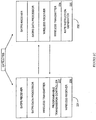
- FIG. 2A shows a unidirectional transmission configuration schematic for a rover 202 and reference station 201 with a rate instruction generator 205 in accordance with an embodiment of the present invention.
- the programmable transmission controller 101 of Figure 1 may receive instructions from different sources.
- the rate instruction generator 205 provides the instructions to the programmable transmission controller 213. Since the rover 202 does not have a wireless transmission capability, the rate instruction generator 205 functions without feedback from the rover 202. For example, a scheduled survey may be made in which the rover 202 moves between a series of points according to a predetermined schedule.
- the rate instruction generator uses the schedule information to determine the data transmission rate.
- the functions of the rate instruction generator may be provided by dedicated hardware, or may be provided by a general purpose processor.
- Figure 2B shows a bidirectional transmission configuration schematic with implicit control for a rover and reference station in accordance with an embodiment of the present invention.
- Figure 2B is an example of a system configuration in which a reference station 221 and a rover 222 have a bidirectional communication capability.
- the rover 222 has a wireless transmitter 224 enabling it to transmit data to the reference station 221.
- the data transmitted by the rover 222 may be received SATPS data, position data, or other information.
- the rover could send to the reference station the current elevation mask being used at the rover.
- the base would not send data below the rover elevation mask to avoid sending data which will not be used at the rover 222.
- the rover 222 could tell the reference station 221 which satellites are being tracked at a particular time. If the line of sight to a satellite is blocked at the rover 222 for any reason, sending that data from the reference station 221 is unnecessary.
- the data transmitted by the rover 222 is received at the reference station 221 by a wireless receiver 225.
- the rate instruction generator 205 uses the received data to determine a transmission rate for the programmable transmission controller. Since the transmission rate is not directly specified by the rover 222, but is determined on the basis of data provided by the rover, this scheme is referred to as an implicit method for data transmission rate control. In general, mobility constraints may limit the processing capability for a rover as compared to that available at a base station.
- An implicit scheme places the computational burden for transmission rate instruction generation on the base station, which is typically better equipped to handle complex algorithms.
- An implicit scheme is also useful when the data transmission rate determination is derived from information that is transmitted from the rover in the normal course of operation, without requiring the transmission of additional explicit instructions for data transmission rate control.
- Table 1 below shows three general modes of operation, each having a range of data rates associated with it.
- the data rate for transmission between the reference station and rover may be measured in fix units.
- a fix unit is the amount of data required to provide position fix.
- Tracking and Positioning Mode normal operation
- the data rate is about 1 to 20 fix units per second.
- Coarse Positioning Mode the data rate is about .05 to 1 fix units per second.
- the data rate is about 1 fix unit every 20 seconds to 1 fix unit per hour.
- the data rates associated with the three modes described above are distinct from the data transmission rate of the wireless link.
- the mode used determines the overall data volume over a period of time, but does not necessarily correlate with the data rate used for wireless transmission.
- a high frequency wireless link e.g., 2.5 GHz
- the wireless receiver 225 and wireless transmitter 226 of the base station 221 may be provided by a telephone device.
- the wireless receiver 227 and wireless transmitter 224 of the rover 222 may also be provided by a telephone device.
- communication may be established using a packet switched service such as the General Packet Radio Service (GPRS) or Cellular Digital Packet Data (CDPD) service.
- GPRS General Packet Radio Service
- CDPD Cellular Digital Packet Data
- the data transmission rate could be implied by the selection of a particular IP socket from a set of available IP sockets that have been associated with different transmission rates. This set of IP sockets may also be differentiated on the basis of data type.
- a reference station network may have multiple simultaneous IP sockets, on each of which is available the reference station data (e.g., data) but at different transmission rates (e.g., 10Hz, 5Hz, 1Hz, .5Hz, and 1Hz).
- sockets could exist on which certain subsets for the measurement data are available, at a range of suitable transmission rates.
- the rover selects which socket to connect to, depending upon the immediate transmission rate requirement. The selection may be carried out at the rover, based on the lowest acceptable frequency and content required at that time, when current variables such as solution filter status, tolerance requirement, distance from stakeout point, satellite availability and geometry, augmentation system status, etc., are taken into consideration.
- FIG. 2C shows a configuration schematic for a rover and base station with explicit control in accordance with an embodiment of the present invention.
- the rover 232 includes a rate instruction generator 235 for determining a data transmission rate instruction for a reference station 231.
- the data transmission rate is transmitted to the reference station 231 by a wireless transmitter 234 and received at the reference station 231 by a wireless receiver 236.
- the programmable transmission controller 237 sets the data transmission rate according to the instruction.
- Explicit control may be used when "on-off control" is desired.
- the rover may set the data transmission rate to zero while in transit from one survey point to another.
- the rover may calculate a transmission rate on the basis of its position or distance from the reference station. Or it may request a subset of the available data types at some rate according to the instantaneous requirements.
- the rate instruction generation function may be programmed into both the base station and rover, thereby allowing both implicit and explicit control of data transmission rate in the system.
- the base may also have multiple, parallel transmission controllers to serve multiple rovers, or it may have a single transmission controller which can take rate instructions from multiple rovers and generate the minimal common set of data required.
- Figure 3 shows a general flow chart 300 for a position determination process using variable data rate transmission in accordance with a method embodiment of the present invention.
- a reference station exercises autonomous control of the data transmission rate without requiring input from the rover.
- the method of Figure 3 corresponds to the system of Figure 2A .
- raw SATPS data is acquired by a reference station.
- the raw SATPS data received by the reference station provides information regarding the state of the satellite system (e.g., a satellite vehicle rising or setting at the horizon.
- the reference station determines the data transmission rate on the basis of information currently available to it. This information may be the state of the satellite constellation, a survey schedule for the rover's activities, pre-programmed rover accuracy requirements, or information relating to the present quality of service for wireless communication. For direct radio transmission that does not use a network, the data transmission rate may be determined on the basis of the potential for interfering with other communications in the same frequency band.
- the overall data transmission rate is a function of the content of a data message (e.g. RTCM message) and the rate at which the message is sent.
- the data transmission rate may be varied by altering the length of a data message, by altering the rate at which a message is transmitted, or both.
- the transmission data is formatted by the reference station. Formatting of the transmission data may include correction calculation and formatting according to the Radio Technical Commission Marine (RTCM) standards (or the Trimble format CMR/CMR+, other manufacturer's proprietary formats). Additional formatting associated with a communication protocol such as UDP/IP may also be performed.
- RTCM Radio Technical Commission Marine
- UDP/IP User Datagram Protocol
- step 320 the data is transmitted.
- the transmission may be a direct broadcast, or it may be transmitted on a network using a connectionless protocol that does not require acknowledgment.
- step 323 the formatted data is received at the rover.
- Figure 4 shows a flow chart 400 for position determination process using variable data rate transmission with implicit rate control in accordance with a method embodiment of the present invention.
- the method of Figure 4 is associated with the system shown in Figure 2B .
- step 404 raw SATPS data is acquired at the rover and at the reference station.
- step 410 data is transmitted by the rover to the reference station.
- the data transmitted by the rover may include raw and processed data.
- the rover may indicate the type of data required from the reference station or data that may be deleted from a message.
- step 414 the reference station generates data rate instructions for the programmable transmission rate controller using data received from the rover.
- the reference station formats the data to be transmitted to the rover. Since bidirectional communication is operational between the reference station and rover, a protocol such as TCP/IP may be used. Compression and error control with acknowledgments may be used.
- step 424 the data is transmitted to the rover.
- the transmission may be made over a direct radio link or a wireless connection to a network.
- step 430 the data is received at the rover.
- Figure 5 shows a flow chart for a position determination process using variable data rate transmission with explicit rate control in accordance with a method embodiment of the present invention.
- step 505 raw data is acquired by the rover and the reference station.
- step 510 the rover determines a data transmission rate to be used by the reference station for data transmission.
- the data transmission rate is determined by the rover on the basis of information that is currently available to it. For example, when staking out a point, the position accuracy requirement is low when the rover is far away from the point. As the rover gets nearer to the point, the accuracy requirement increases and thus the data transmission rate may be increased accordingly.
- the data transmission rate instructions are transmitted to the reference station.
- the transmission may be made by a direct radio link or may be made across a wireless link to a network.
- bidirectional communication between the rover and reference station would be carried out using the same protocol regardless of which entity initiated the communication.
- the reference station may use a different protocol than the rover.
- a reference station typically does not share the transmitter power constraint imposed on the rover by its requirement for mobility.
- a reference station may transmit data to a rover by direct radio link, while the rover uses a low power link to a cellular network.
- the data required by the rover is formatted by the reference station. Formatting of the transmission data may include correction calculation and formatting according to the Radio Technical Commission Marine (RTCM) standards or to other proprietary standards. Additional formatting associated with a communication protocol such as TCP/IP may also be performed.
- RTCM Radio Technical Commission Marine
- step 525 the formatted transmission data is transmitted to the rover.
- the transmission may be made over a direct radio link or a wireless connection to a network.
- step 530 the data is received at the rover.
- the data from base to rover may not be formatted at all, or it may be passed through compression or encryption algorithms with recovery at the receiving end, while still having an element of dynamic control based on the factors described.
- the generation of data rate transmission instructions may be performed local to either a base station or a rover in alternative fashion, by executing the appropriate instructions on a processor.
- Either the base station or the rover may control which type of data is sent and how often, based on the prevailing conditions and immediate requirements. Certain data may be determined by either the base or rover to be redundant and thus removed from the transmission stream.
- the data transmission rate may be altered by selective transmission of data. For example, during initialization a rover requires all measurement types, at a given rate. After initialization, it may only use a subset of the measurements. For example the rover might revert to L1 phase only (or phase rate only), at certain times and under certain conditions.
- SATPS events may be used by either the rover or the reference station as parameters for modifying the data transmission rate.
- the reference station and/or rover may log data that it receives.
- a discussion of SATPS events that may influence data transmission rates is provided in U.S. Patent No. 5,916,300, issued to Kirk et al on 6/29/99 .
- the data transmitted over the wireless link includes data for ambiguities and data for positioning.
- Data for ambiguities may include data required to resolve new satellite phase ambiguities, and to maintain these ambiguities (for example, after a cycle-slip or temporary loss of lock due to an obstruction to the line-of-site between the rover antenna and a satellite).
- Data for ambiguities typically does not require a continuous data stream.
- Data for positioning usually comprises a continuous data stream with some data rate greater than zero. The data rate is a function of various parameters such as position accuracy and position latency (difference between the time of position and the current time).
- differential GPS positioning may be carried out using the code phase measurements only, or phase smoothed code measurements, in which case ambiguities are not required to be solved, but an economic advantage can be gained through dynamic variation of message type and rate as a function of rover requirements.
- one of the initial 5 satellites may set below the horizon, leaving 4 satellites in a set of satellites called Set-A.
- Another new satellite may rise above the horizon.
- Set-B Once the phase ambiguity of the new satellite has been resolved, but not before, it can be added to form a set of 5 satellites called Set-B.
- any satellite from Set-A can be removed from the system (for example, obstructed from view) to leave a new set of 4 satellites called Set-C.
- Set-C Such a process may occur any number of times.
- the current visible set drops to less than 4 satellites, then the system becomes "uninitialized” and must wait for a total of 5 satellites to "initialize”.
- one or more satellites may be temporarily removed from the set, and added back, providing that ambiguities are maintained on at least 4 satellites at every measurement epoch. To reduce the chance of becoming uninitialized, it is important to resolve ambiguities on satellites as soon as possible, preferably using a high data rate from the base station.
- the data for ambiguities is typically only required prior to initialization, and when resolving ambiguities for the current set of visible satellites. At all other times, data for ambiguities may not be required. Thus, if there is no concurrent requirement for data for positioning and data for ambiguities, the data link may be disabled at such times to reduce the expense of operating the RTK system. Optionally, data can be re-enabled at any time to perform tests on the set of ambiguities, to ensure that they were correctly resolved.
- data for ambiguities may be required for the following conditions: (i) A new satellite becomes available (rises above the horizon, or user specified elevation mask); (ii) a cycle-slip or loss of lock occurs on any tracked satellite; or (iii) to check the current set of ambiguities.
- the rover needs to enable the data stream from the base.
- the handling of initialization related events is a component of the overall data rate generation process. Although the requirement for positioning data may be set to zero, while a rover is in transit between survey locations, certain events may trigger data transmission in order to maintain initialization.
- Figure 6 shows a flow chart 600 of a rover process loop that is responsive to events affecting initialization.
- the loop watches for events that may introduce ambiguities and enables data transmission so that the ambiguities may be resolved. Once all ambiguities are resolved, then the data stream can be disabled. Commands to enable and disable the data stream are sent from the rover to the base.
- step 605 the system is turned on and the loop is started. The loop may run continuously until the system is turned off.
- step 610 a check is made for the availability of a new satellite. If a new satellite is available, the step 615 is executed by setting a "Send Enable Request" (SER) flag. If a new satellite is not available, then the existing constellation of satellites is checked for cycle-slips in step 620. If a cycle-slip exists, then step 615 is executed. If a cycle-slip is not detected, then the requirement for positioning data is checked in step 625.
- SER Send Enable Request
- the condition "compute position” 625 depends on the user's requirement to obtain a position in real-time.
- a handheld controller can be used to set and reset the condition "compute position" when a survey mark needs to be observed, or when a stake-out is required (a method to locate a position at which a physical survey mark is to placed).
- a machine control user interface can be used to set and reset this condition when the machine is actively controlling an earth-moving blade. If data is required for a position computation, then step 615 is executed.
- step 630 a check is made to see if ambiguities are resolved. If ambiguities are resolved, then the SER flag is reset in step 635. If ambiguities are not resolved, then the SER flag status is checked in step 640.
- step 640 If the SER flag is set in step 640, then a check is made for data reception in step 665. If data is being received in step 665, then the loop is repeated. If data is not being received in step 665, then step 670 is executed and an "Enable Request" command is sent to the base station before repeating the loop.
- step 640 If the SER flag is not set in step 640, then a check is made for data reception in step 675. If data is being received at step 675, then a "Disable Request" is sent to the base station before repeating the loop. If the SER flag is not set in step 640 and data is not being received at step 745, then the loop is repeated.
- FIG. 7 shows a general flow chart 700 for a process similar to that of Figure 6 , in which two data requirements are reviewed.
- step 705 the system is turned on and the loop is started. The loop may run continuously until the system is turned off.
- step 710 a check is made for a positioning data requirement. If positioning data is required, then the SER flag is set in Step 720. If positioning data is not required, then a check is made in step 715 for an ambiguity data requirement. If data for ambiguities is required (ambiguities not resolved), then the SER flag is set in step 720. If ambiguities are resolved and data not required, then the SER flag is reset in step 725.
- step 730 the SER flag status is checked. If the SER flag is set in step 730, then a check is made for data reception in step 735. If data is being received in step 735, then the loop is repeated. If data is not being received in step 735, then step 740 is executed and an "Enable Request" command is sent to the base station before repeating the loop.
- step 730 If the SER flag is not set in step 730, then a check is made for data reception in step 745. If data is being received at step 745, then a "Disable Request" is sent to the base station before repeating the loop. If the SER flag is not set in step 730 and data is not being received at step 745, then the loop is repeated.
- Figure 8 shows a flow chart diagram 800 for a base station process for data transmission control.
- the base station process shown is less complex than the rover process since the base station does not have to check for satellite constellation changes. In the event of a rising or setting satellite, the rover will inform the base station. However, it is necessary for the base station to check for cycle slips, since a cycle slip may occur independently at either the rover or base station.
- step 805 the system is turned on and the loop is started. The loop may run continuously until the system is turned off.
- step 810 the base station checks for a cycle-slip on any satellite being tracked by the rover and base station. If there is a cycle-slip, the base station enables data transmission to the rover in step 815. If the base station does not detect a cycle-slip in step 810, it checks for a an "Enable request" from the rover in step 820. If an "Enable Request" has been received, the base station enables data transmission in step 815. If an "Enable Request” has not been received in step 820, the base station checks to see if a "Disable Request" has been received from the rover in step 825. If a "Disable Request has been received in step 825, the base station repeats the loop. If a "Disable Request” has been received in step 825, the base station disables data transmission in step 830 prior to repeating the loop.
- FIG. 9 shows a flow chart diagram 900 for a base station process that includes the generation of data transmission rate instructions in addition to the enablement of data transmission.
- step 905 the system is turned on and the loop is started. The loop may run continuously until the system is turned off.
- step 910 the base station checks for data rate transmission instructions from the rover or rovers. If rate instructions are received from the rover in step 910, the rate instructions are processed and transmission enabled accordingly in step 915. If rate instructions from the rover are not received in step 910, the base station checks for a cycle-slip in step 920. If the base station detects a cycle slip in step 920, a data transmission rate is determined and transmission enabled accordingly in step 925.
- the base station checks for receipt of a "Disable Request" from the rover in step 930. If a "Disable Request” has not been received from the rover in step 930, the loop is repeated. If a "Disable Request" is received in step 930, the base station disables transmission before repeating the loop.
- Figure 10 shows a flow chart diagram 1000 for a rover process that includes rate instruction generation.
- step 1005 the system is turned on and the loop is started.
- step 1010 the rover checks to see if there are ambiguities that require resolution. If it is determined in step 1010 that data for ambiguities is required, a "Need Ambiguities" (NA) flag is set in step 1015. If it is determined in step 1010 that there are no ambiguities that require resolution, the rover checks to see if data for positioning is required in step 1025. If data for positioning is required, a "Need Positions" (NP) flag is set in step 1030. If data for positioning is not required, the NP flag is reset in step 1035.
- NA Need Ambiguities
- step 1040 the status of the NA and NP flags is checked. If either of the NA and NP flags is set, a data reception check is made in step 1045. If data is not being received, then data rate transmission instructions are computed and sent with an "Enable request" to the base station in step 1050. It should be recognized that the data rate requirements for positioning and ambiguity resolution may be different. Therefore the generation of rate instructions depends on whether positioning is required (NP flag set) and whether ambiguity resolution is required (NA flag set).
- the system may be positioning with one data rate when a change of the ambiguity resolution state occurs (flag NA set). If data is being received in step 1045, a change in NA or NP flag status is determined in step 1060. If NA or NP flag status has changed, then step 1050 is executed, which results in generation of a new set of rate instructions followed by a transmission of these instructions from the rover to the base. This may increase or decrease the data rate. If neither the NA or NP flag status has changed in step 1060, the loop is repeated.
- step 1055 a data reception check is made in step 1055. If data is not being received in step 1055, the loop is repeated. If data is being received, then a "Disable Request" is sent to the base station in step 1070 before repeating the loop.
- the data for positioning is only enabled for a fraction of the time of the total survey. During the remaining time, the surveyor is moving between survey marks, and data for ambiguities will only be required infrequently.
- the rover only needs the highest accuracy data when actually on a survey line but not when making turns etc.
- the method described can be used to significantly reduce the total quantity of data transmitted from a base station or base network.
- reducing the quantity of data has a direct cost savings (charged per byte).
- reducing the data rate can reduce broadcast congestion. It can also allow the use of TDMA (Time Division Multiple Access) using a single transmit frequency.
- the Rate Instruction Generator at the base must process information from all the rovers. For example, in the simplified case in which data is being enabled/disabled (constant rate), the base enables data transmission when any rover requests "enable data" (this can be considered equivalent to a logical OR operation), and the base disables data transmission when every rover requests "disable data” (this can be considered equivalent to a logical AND operation). If the data rate is variable, as determined by the Rate Instruction Generator, then data is always enabled at the fastest rate required by any rover, or the lowest common set of requirements at any time. Alternatively, the base may serve multiple rovers on multiple parallel communications channels.
Landscapes
- Engineering & Computer Science (AREA)
- Radar, Positioning & Navigation (AREA)
- Remote Sensing (AREA)
- Computer Networks & Wireless Communication (AREA)
- Physics & Mathematics (AREA)
- General Physics & Mathematics (AREA)
- Mobile Radio Communication Systems (AREA)
- Position Fixing By Use Of Radio Waves (AREA)
- Radio Relay Systems (AREA)
- Detection And Prevention Of Errors In Transmission (AREA)
- Communication Control (AREA)
Claims (31)
- Verfahren für eine Datenübermittlung mit variabler Übermittlungsrate für die Kommunikation von Echtzeitdaten eines Satellitenpositionsbestimmungssystems zwischen einem Rover (102; 202; 222; 232) und einer Referenzstation (101; 201; 221; 231), wobei der Rover und die Referenzstation Elemente eines Real-Time Kinematic (RTK) Positionsbestimmungssystems sind; wobei das Verfahren folgendes umfasst:das Erfassen (303; 404; 505) von Rohdaten des Satellitenpositionsbestimmungssystems (103) an der genannten Referenzstation;das Umwandeln (313; 420; 520) der genannten Rohdaten des Satellitenpositionsbestimmungssystems in formatierte Daten;das Bestimmen (310; 414; 510, 515) einer Übermittlungsrate für die genannten formatierten Daten; unddas Steuern der Übermittlung (320; 424; 525) der genannten formatierten Daten an den genannten Rover unter Verwendung einer programmierbaren Übermittlungssteuereinheit und eines drahtlosen Senders;dadurch gekennzeichnet, dass das Bestimmen der Übermittlungsrate auf der für den Rover erforderlichen (510) Positionsgenauigkeit basiert.
- Verfahren nach Anspruch 1, wobei:das Bestimmen der Übermittlungsrate für die genannten Daten ferner auf aktuellen Bedingungen einer Reihe von Kriterien basiert.
- Verfahren nach Anspruch 1, wobei:das Bestimmen der Übermittlungsrate für die genannten Daten ferner ausgeführt wird gemäß einer vorbestimmten Reihe von Kriterien; unddas Steuern der Übermittlung das dynamische Steuern der Übermittlung der genannten Daten an den genannten Rover unter Verwendung einer programmierbaren Übermittlungssteuereinheit und eines drahtlosen Senders umfasst.
- Verfahren nach Anspruch 1 oder 2 oder 3, wobei das Verfahren ferner das Empfangen von Daten (410; 515) von dem genannten Rover (102; 202; 222; 232) an der genannten Referenzstation (101; 201; 221; 231) aufweist.
- Verfahren nach Anspruch 4, wobei die genannten Daten Steuerbefehle für die Übermittlungsrate umfassen.
- Verfahren nach Anspruch 1 oder 2 oder 3, wobei das Bestimmen der Übermittlungsrate ferner auf Ereignissen des Satellitenpositionsbestimmungssystems basiert, wobei es sich bei den Ereignissen des Satellitenpositionsbestimmungssystems um Cycle Slips oder Konfigurationsanpassungen handelt.
- Verfahren nach Anspruch 1 oder 2 oder 3, wobei das Bestimmen der Übermittlungsrate ferner auf der Art der übermittelten Daten basiert.
- Verfahren nach Anspruch 1 oder 2 oder 3, wobei das Bestimmen der Übermittlungsrate ferner auf einer Anforderung für Daten in Bezug auf Uneindeutigkeiten basiert.
- Verfahren nach Anspruch 1 oder 2 oder 3, wobei die genannte Datenübermittlung ausgeführt wird unter Verwendung von TCP/IP und einem IP-Socket, das aus einer Mehrzahl von IP-Sockets ausgewählt wird.
- Verfahren nach Anspruch 1 oder 2 oder 3, wobei die Datenübermittlungsrate ferner auf der Basis der Positionsextrapolationsgenauigkeit des Rover (102; 202; 222; 232) bestimmt wird.
- Computerlesbares Medium, das ausführbare Anweisungen aufweist, die, wenn sie in einem Echtzeit-Satellitenpositionsbestimmungssystem mit einer Referenzstation (101; 201; 221; 231) und einem Rover (102; 202; 222; 232) ausgeführt werden, bewirken, dass das System eine Datenübermittlungsrate zwischen der genannten Referenzstation und dem genannten Rover anpasst, wobei der Rover und die Referenzstation Elemente eines Real-Time Kinematic (RTK) Positionsbestimmungssystems sind; wobei die Anweisungen folgendes umfassen:Anweisungen zum Erfassen (303; 404; 505) von Rohdaten des Satellitenpositionsbestimmungssystems (103) an der genannten Referenzstation;Anweisungen zum Umwandeln (313; 420; 520) der genannten Rohdaten des Satellitenpositionsbestimmungssystems in formatierte Daten;Anweisungen zum Bestimmen (310; 414; 510, 515) einer Übermittlungsrate für die genannten formatierten Daten; undAnweisungen zum Übermitteln (320; 424; 525) der genannten formatierten Daten an den genannten Rover unter Verwendung der genannten Übermittlungsrate;dadurch gekennzeichnet, dass die Anweisungen zum Bestimmen der Übermittlungsrate auf der für den Rover erforderlichen Positionsgenauigkeit basiert.
- Computerlesbares Medium nach Anspruch 11, wobei dieses ferner Anweisungen für den Empfang von Daten von dem genannten Rover (102; 202; 222; 232) an der genannten Referenzstation aufweist.
- Computerlesbares Medium nach Anspruch 12, wobei die genannten Daten Anweisungen zur Steuerung der genannten Übermittlungsrate umfassen.
- Computerlesbares Medium nach Anspruch 11, wobei die Anweisungen zum Bestimmen der Übermittlungsrate ferner auf Ereignissen des Satellitenpositionsbestimmungssystems basiert, wobei es sich bei den Ereignissen des Satellitenpositionsbestimmungssystems um Cycle Slips oder Konfigurationsanpassungen handelt.
- Computerlesbares Medium nach Anspruch 11, wobei die Anweisungen zum Bestimmen der Übermittlungsrate ferner auf der Art der übermittelten Daten basieren.
- Computerlesbares Medium nach Anspruch 11, wobei die Anweisungen zum Bestimmen der Datenübermittlungsrate ferner auf der Basis der Positionsextrapolationsgenauigkeit des Rover (102; 202; 222; 232) erzeugt werden.
- Computerlesbares Medium nach Anspruch 11, wobei die Anweisungen zum Bestimmen der Datenübermittlungsrate ferner auf der Basis einer Anforderung für Daten in Bezug auf Uneindeutigkeiten erzeugt werden.
- System für eine Datenübermittlung mit variabler Übermittlungsrate für die Kommunikation von Echtzeitdaten eines Satellitenpositionsbestimmungssystems zwischen einem Rover (102; 202; 222; 232) und einer Referenzstation (101; 201; 221; 231), wobei der Rover und die Referenzstation Elemente eines Real-Time Kinematic (RTK) Positionsbestimmungssystems sind; wobei das System folgendes umfasst:Einrichtungen (110) zum Erfassen von Rohdaten des Satellitenpositionsbestimmungssystems an der genannten Referenzstation;Einrichtungen (111) zum Umwandeln der genannten Rohdaten des Satellitenpositionsbestimmungssystems in formatierte Daten;Einrichtungen (113; 213, 205; 205, 225) zum Bestimmen einer Übermittlungsrate für die genannten formatierten Daten; undeine programmierbare Übermittlungssteuereinheit (113; 213; 237) und einen drahtlosen Sender (112; 226) zum Steuern der Übermittlung der genannten formatierten Daten an den genannten Rover;dadurch gekennzeichnet, dass das Bestimmen der Übermittlungsrate auf der für den Rover erforderlichen Positionsgenauigkeit basiert.
- Real-Time Kinematic (RTK) Positionsbestimmungssystem nach Anspruch 18, wobei:die Einrichtungen zum Erfassen von Rohdaten des Satellitenpositionsbestimmungssystems an der genannten Referenzstation einen Satellitenpositionsbestimmungssystemempfänger (110) für den Empfang von Satellitenpositionsbestimmungssystemdaten (103) aufweist; unddie programmierbare Übermittlungssteuereinheit (113; 213; 237) eine programmierbare Übermittlungssteuereinheit zum Steuern der Rate aufweist, mit der die Daten durch den drahtlosen Sender (112) übermittelt werden;der genannte Rover (102; 220; 222; 232) einen Satellitenpositionsbestimmungssystemempfänger (120) für den Empfang von Satellitenpositionsbestimmungssystemdaten (104) aufweist, einen drahtlosen Empfänger (122; 224; 234) für den Empfang von Daten, die von der genannten Referenzstation übermittelt werden, und einen Prozessor (121; 227; 234) zur Positionsbestimmung auf der Basis der genannten Satellitenpositionsbestimmungssystemdaten (104) sowie der von der genannten Referenzstation empfangenen Daten.
- System nach Anspruch 18, wobei die Einrichtungen zum Erfassen der Rohdaten des Satellitenpositionsbestimmungssystems an der genannten Referenzstation einen Satellitenpositionsbestimmungssystemempfänger (110) für den Empfang von Satellitenpositionsbestimmungssystemdaten (103) umfassen; wobei die Referenzstation ferner folgendes umfasst:den drahtlosen Sender (112; 226) für die Datenübermittlung; unddie programmierbare Übermittlungssteuereinheit (113; 213; 237) zum Steuern der Rate, mit der die genannten Daten übermittelt werden.
- System nach Anspruch 18, wobei der Rover (102; 202; 222; 232) folgendes umfasst:einen Satellitenpositionsbestimmungssystemempfänger (120) für den Empfang von Satellitenpositionsbestimmungssystemdaten (104);einen drahtlosen Empfänger (122; 224) für den Empfang von Daten, die von einer Referenzstation übermittelt werden; undeinen Prozessor (121; 227) zur Positionsbestimmung auf der Basis der genannten Satellitenpositionsbestimmungssystemdaten und der Daten, die von der genannten Referenzstation empfangen werden.
- System nach Anspruch 20, wobei die genannte programmierbare Übermittlungssteuereinheit (213; 237) dynamisch die Rate steuert, mit der die genannten Daten übermittelt werden.
- System nach Anspruch 19 oder 20 oder 22, wobei die genannte Referenzstation (101; 201; 221; 231) ferner einen Prozessor zum Erzeugen von Übermittlungsratenanweisungen zur Programmierung der genannten programmierbaren Übermittlungsratensteuereinheit (212; 237) aufweist.
- System nach Anspruch 20 oder 21, wobei es sich bei der genannten Fähigkeit zur Übermittlung mit variabler Rate um eine dynamisch gesteuerte Fähigkeit zur Übermittlung mit variabler Datenrate handelt.
- System nach Anspruch 22 oder 24, wobei der genannte Rover (232) ferner einen Prozessor (235) zum Erzeugen von Übermittlungsratenanweisungen zur dynamischen Steuerung der programmierbaren Übermittlungssteuereinheit handelt.
- System nach Anspruch 19 oder 25, wobei die genannten Anweisungen ferner teilweise aus Ereignisdaten des Satellitenpositionsbestimmungssystems erzeugt werden, wobei es sich bei den Ereignissen des Satellitenpositionsbestimmungssystems um Cycle Slips oder Konfigurationsanpassungen handelt.
- System nach Anspruch 19 oder 25, wobei der Rover (232) einen drahtlosen Sender (234) zum Übermitteln von Daten an die Referenzstation (231) aufweist.
- System nach Anspruch 27, wobei es sich bei den genannten Anweisungen zur Steuerung der genannten programmierbaren Ratensteuereinheit um implizite Anweisungen handelt.
- System nach Anspruch 25 und 27, wobei die von dem Rover übermittelten Daten explizite Anweisungen zur dynamischen Steuerung der genannten programmierbaren Übermittlungsratensteuereinheit aufweist.
- System nach Anspruch 27, wobei die von dem Rover übermittelten Daten explizite Anweisungen zur Programmierung der genannten programmierbaren Übermittlungsratensteuereinheit aufweist.
- System nach Anspruch 29 oder 30, wobei die genannten expliziten Anweisungen ferner teilweise auf der Basis einer Anforderung für Daten in Bezug auf Uneindeutigkeiten erzeugt werden.
Applications Claiming Priority (3)
| Application Number | Priority Date | Filing Date | Title |
|---|---|---|---|
| US209613 | 1988-06-21 | ||
| US10/209,613 US6985104B2 (en) | 2002-07-29 | 2002-07-29 | Method and system for variable data rate transmission in RTK GPS survey system |
| PCT/US2002/036842 WO2004011958A1 (en) | 2002-07-29 | 2002-11-15 | A method and system for variable data rate transmission |
Publications (2)
| Publication Number | Publication Date |
|---|---|
| EP1532467A1 EP1532467A1 (de) | 2005-05-25 |
| EP1532467B1 true EP1532467B1 (de) | 2012-05-09 |
Family
ID=31187094
Family Applications (1)
| Application Number | Title | Priority Date | Filing Date |
|---|---|---|---|
| EP02807635A Expired - Lifetime EP1532467B1 (de) | 2002-07-29 | 2002-11-15 | Verfahren und vorrichtung zur übertragungs mit variabler datenrate |
Country Status (5)
| Country | Link |
|---|---|
| US (2) | US6985104B2 (de) |
| EP (1) | EP1532467B1 (de) |
| AT (1) | ATE557299T1 (de) |
| AU (1) | AU2002368123A1 (de) |
| WO (1) | WO2004011958A1 (de) |
Cited By (1)
| Publication number | Priority date | Publication date | Assignee | Title |
|---|---|---|---|---|
| CN110673182A (zh) * | 2019-09-29 | 2020-01-10 | 清华大学 | 一种gnss高精度快速定位方法及装置 |
Families Citing this family (20)
| Publication number | Priority date | Publication date | Assignee | Title |
|---|---|---|---|---|
| US6985104B2 (en) * | 2002-07-29 | 2006-01-10 | Trimble Navigation Limited | Method and system for variable data rate transmission in RTK GPS survey system |
| JP2004361186A (ja) * | 2003-06-03 | 2004-12-24 | Sony Corp | 位置情報測位装置 |
| GB2417391B (en) | 2004-08-18 | 2007-04-18 | Wecomm Ltd | Transmitting data over a network |
| US9621473B2 (en) | 2004-08-18 | 2017-04-11 | Open Text Sa Ulc | Method and system for sending data |
| EP2026085B1 (de) * | 2004-10-21 | 2012-03-07 | Nokia Corporation | Zurverfügungstellung von Trägerphasenmessungen auf Anfrage zur Positionsbestimmung auf Satellitenbasis |
| JP4912739B2 (ja) * | 2006-05-16 | 2012-04-11 | 株式会社トプコン | Rtk−gps測量システム |
| US7855678B2 (en) * | 2007-05-16 | 2010-12-21 | Trimble Navigation Limited | Post-mission high accuracy position and orientation system |
| US20090093959A1 (en) * | 2007-10-04 | 2009-04-09 | Trimble Navigation Limited | Real-time high accuracy position and orientation system |
| WO2010016783A1 (en) * | 2008-08-04 | 2010-02-11 | Magellan Navigation, Inc. | Space based augmentation system ranging signal applied to l1 real time kinematic |
| US8626473B2 (en) * | 2008-08-07 | 2014-01-07 | Trimble Navigation Limited | Real-time transmission of survey data |
| US8571800B2 (en) | 2008-08-07 | 2013-10-29 | Trimble Navigation Limited | User interactive actual time networked survey system |
| US9588226B2 (en) * | 2008-12-23 | 2017-03-07 | Trimble Inc. | System and method for providing position correction data |
| US8983685B2 (en) * | 2010-07-30 | 2015-03-17 | Deere & Company | System and method for moving-base RTK measurements |
| US20120150573A1 (en) * | 2010-12-13 | 2012-06-14 | Omar Soubra | Real-time site monitoring design |
| US8554135B2 (en) * | 2011-03-15 | 2013-10-08 | Trimble Navigation Limited | Controlling power dissipation in a base station of a navigation satellite system (NSS) |
| US9386127B2 (en) | 2011-09-28 | 2016-07-05 | Open Text S.A. | System and method for data transfer, including protocols for use in data transfer |
| KR102294634B1 (ko) * | 2015-08-12 | 2021-08-26 | 현대자동차주식회사 | 네트워크에서 통신 노드의 동작 방법 |
| CN109309560B (zh) * | 2018-10-25 | 2020-08-11 | 清华大学 | 基于北斗rdss的共视数据传递与时间同步方法及系统 |
| US11181643B2 (en) * | 2019-04-30 | 2021-11-23 | Verizon Patent And Licensing Inc. | Providing a location as a service |
| EP3971615A1 (de) | 2020-09-22 | 2022-03-23 | HERE Global B.V. | Bestimmung von übertragungseigenschaften zur übertragung von korrekturdaten |
Family Cites Families (11)
| Publication number | Priority date | Publication date | Assignee | Title |
|---|---|---|---|---|
| US5379224A (en) * | 1991-11-29 | 1995-01-03 | Navsys Corporation | GPS tracking system |
| US5311194A (en) | 1992-09-15 | 1994-05-10 | Navsys Corporation | GPS precision approach and landing system for aircraft |
| US5748651A (en) * | 1995-05-05 | 1998-05-05 | Trumble Navigation Limited | Optimum utilization of pseudorange and range rate corrections by SATPS receiver |
| US5678182A (en) * | 1995-06-19 | 1997-10-14 | Trimble Navigation Limited | Self-locating radio system that automatically configures to the radio regulations for the location |
| US6574211B2 (en) * | 1997-11-03 | 2003-06-03 | Qualcomm Incorporated | Method and apparatus for high rate packet data transmission |
| US6268824B1 (en) * | 1998-09-18 | 2001-07-31 | Topcon Positioning Systems, Inc. | Methods and apparatuses of positioning a mobile user in a system of satellite differential navigation |
| US6229478B1 (en) * | 1998-11-05 | 2001-05-08 | Trimble Navigation Limited | Near-real time DGPS network and server system |
| KR100339988B1 (ko) | 2000-06-29 | 2002-06-10 | 강동호 | 부호분할 다중접속방식의 서킷 방식 무선 데이터 통신을이용한 알티케이 지피에스 측위를 위한 데이터 전송연동장치 |
| US6492945B2 (en) * | 2001-01-19 | 2002-12-10 | Massachusetts Institute Of Technology | Instantaneous radiopositioning using signals of opportunity |
| US6567041B1 (en) * | 2001-04-18 | 2003-05-20 | Sprint Spectrum, L.P. | Network system and method for a remote reference receiver system |
| US6985104B2 (en) * | 2002-07-29 | 2006-01-10 | Trimble Navigation Limited | Method and system for variable data rate transmission in RTK GPS survey system |
-
2002
- 2002-07-29 US US10/209,613 patent/US6985104B2/en not_active Expired - Lifetime
- 2002-11-15 AU AU2002368123A patent/AU2002368123A1/en not_active Abandoned
- 2002-11-15 AT AT02807635T patent/ATE557299T1/de active
- 2002-11-15 WO PCT/US2002/036842 patent/WO2004011958A1/en not_active Ceased
- 2002-11-15 EP EP02807635A patent/EP1532467B1/de not_active Expired - Lifetime
-
2005
- 2005-10-28 US US11/261,123 patent/US7456786B2/en not_active Expired - Lifetime
Cited By (1)
| Publication number | Priority date | Publication date | Assignee | Title |
|---|---|---|---|---|
| CN110673182A (zh) * | 2019-09-29 | 2020-01-10 | 清华大学 | 一种gnss高精度快速定位方法及装置 |
Also Published As
| Publication number | Publication date |
|---|---|
| AU2002368123A1 (en) | 2004-02-16 |
| WO2004011958A1 (en) | 2004-02-05 |
| EP1532467A1 (de) | 2005-05-25 |
| US20040145516A1 (en) | 2004-07-29 |
| US6985104B2 (en) | 2006-01-10 |
| US20060066479A1 (en) | 2006-03-30 |
| ATE557299T1 (de) | 2012-05-15 |
| US7456786B2 (en) | 2008-11-25 |
Similar Documents
| Publication | Publication Date | Title |
|---|---|---|
| EP1532467B1 (de) | Verfahren und vorrichtung zur übertragungs mit variabler datenrate | |
| US7911378B2 (en) | System and method for applying code corrections for GNSS positioning | |
| EP3444636B1 (de) | Differenzielles globales positionierungssystem und positionierungsverfahren dafür | |
| CN103370635B (zh) | 用于确定时钟校正的方法和系统 | |
| AU663490B2 (en) | Vehicle tracking system employing global positioning system (GPS) satellites | |
| EP1802991B1 (de) | Positionsbestimmung auf satellitenbasis | |
| RU2608763C2 (ru) | Усовершенствованные синхронизация по времени и передача значений времени для группировок спутников посредством определения расстояния между спутниками и использования источника точного времени | |
| US6285315B1 (en) | Positioning systems | |
| US8654009B2 (en) | Prediction refresh method for ephemeris extensions | |
| US6684158B1 (en) | Method for aiding a global positioning system | |
| JP7246778B2 (ja) | 高精度な単独測位機能を有する自律型基準局 | |
| US7800531B2 (en) | High precision positioning system | |
| CN106796296B (zh) | 具有置信指数的定位和导航接收机 | |
| WO2014022930A1 (en) | Low latency centralized rtk system | |
| KR20190029929A (ko) | 의사 위성항법 신호 중계 장치 및 의사 위성항법 신호 중계 장치의 동작 방법 | |
| US20120075140A1 (en) | Method and System for a Virtual Wide Area GNSS Reference Network | |
| US20100094554A1 (en) | Systems and Methods for Accessing Data Over a Short-range Data Link to Enhance the Performance of a Navigational Unit | |
| CN119916411B (zh) | 确定卫星钟差的方法及装置 | |
| KR20080065040A (ko) | 위성항법 신호보정을 위한 장치 및 방법 | |
| CN111885483B (zh) | 一种自行走设备精确定位的方法及系统 | |
| CN114779296A (zh) | 一种全天时全天候的卫星广域精密定位终端 | |
| El-Mowafy et al. | Machine automation using RTK GPS positioning | |
| Moon et al. | GPS-RTK solution using WAVE communication for vehicle | |
| EP2541276A1 (de) | Kompakte Langzeitsatellitenmodelle | |
| Lapucha et al. | High‐Rate Precise Real‐Time Positioning Using Differential Carrier Phase |
Legal Events
| Date | Code | Title | Description |
|---|---|---|---|
| PUAI | Public reference made under article 153(3) epc to a published international application that has entered the european phase |
Free format text: ORIGINAL CODE: 0009012 |
|
| 17P | Request for examination filed |
Effective date: 20050223 |
|
| AK | Designated contracting states |
Kind code of ref document: A1 Designated state(s): AT BE BG CH CY CZ DE DK EE ES FI FR GB GR IE IT LI LU MC NL PT SE SK TR |
|
| AX | Request for extension of the european patent |
Extension state: AL LT LV MK RO SI |
|
| DAX | Request for extension of the european patent (deleted) | ||
| 17Q | First examination report despatched |
Effective date: 20070615 |
|
| RIN1 | Information on inventor provided before grant (corrected) |
Inventor name: LARGE, PETER Inventor name: ALLISON, MICHAEL, TIMO Inventor name: KIRK, GEOFFREY, R. |
|
| REG | Reference to a national code |
Ref country code: DE Ref legal event code: R079 Ref document number: 60242911 Country of ref document: DE Free format text: PREVIOUS MAIN CLASS: G01S0005140000 Ipc: G01S0019040000 |
|
| GRAP | Despatch of communication of intention to grant a patent |
Free format text: ORIGINAL CODE: EPIDOSNIGR1 |
|
| RIC1 | Information provided on ipc code assigned before grant |
Ipc: G01S 19/04 20100101AFI20111031BHEP |
|
| GRAS | Grant fee paid |
Free format text: ORIGINAL CODE: EPIDOSNIGR3 |
|
| GRAA | (expected) grant |
Free format text: ORIGINAL CODE: 0009210 |
|
| AK | Designated contracting states |
Kind code of ref document: B1 Designated state(s): AT BE BG CH CY CZ DE DK EE ES FI FR GB GR IE IT LI LU MC NL PT SE SK TR |
|
| REG | Reference to a national code |
Ref country code: GB Ref legal event code: FG4D Ref country code: DE Ref legal event code: R081 Ref document number: 60242911 Country of ref document: DE Owner name: TRIMBLE INC. (N.D.GES.D.STAATES DELAWARE), SUN, US Free format text: FORMER OWNER: TRIMBLE NAVIGATION LTD., SUNNYVALE, CALIF., US |
|
| REG | Reference to a national code |
Ref country code: CH Ref legal event code: EP Ref country code: AT Ref legal event code: REF Ref document number: 557299 Country of ref document: AT Kind code of ref document: T Effective date: 20120515 |
|
| REG | Reference to a national code |
Ref country code: IE Ref legal event code: FG4D |
|
| REG | Reference to a national code |
Ref country code: DE Ref legal event code: R096 Ref document number: 60242911 Country of ref document: DE Effective date: 20120628 |
|
| REG | Reference to a national code |
Ref country code: NL Ref legal event code: VDEP Effective date: 20120509 |
|
| PG25 | Lapsed in a contracting state [announced via postgrant information from national office to epo] |
Ref country code: FI Free format text: LAPSE BECAUSE OF FAILURE TO SUBMIT A TRANSLATION OF THE DESCRIPTION OR TO PAY THE FEE WITHIN THE PRESCRIBED TIME-LIMIT Effective date: 20120509 Ref country code: CY Free format text: LAPSE BECAUSE OF FAILURE TO SUBMIT A TRANSLATION OF THE DESCRIPTION OR TO PAY THE FEE WITHIN THE PRESCRIBED TIME-LIMIT Effective date: 20120509 Ref country code: SE Free format text: LAPSE BECAUSE OF FAILURE TO SUBMIT A TRANSLATION OF THE DESCRIPTION OR TO PAY THE FEE WITHIN THE PRESCRIBED TIME-LIMIT Effective date: 20120509 |
|
| REG | Reference to a national code |
Ref country code: AT Ref legal event code: MK05 Ref document number: 557299 Country of ref document: AT Kind code of ref document: T Effective date: 20120509 |
|
| PG25 | Lapsed in a contracting state [announced via postgrant information from national office to epo] |
Ref country code: PT Free format text: LAPSE BECAUSE OF FAILURE TO SUBMIT A TRANSLATION OF THE DESCRIPTION OR TO PAY THE FEE WITHIN THE PRESCRIBED TIME-LIMIT Effective date: 20120910 Ref country code: GR Free format text: LAPSE BECAUSE OF FAILURE TO SUBMIT A TRANSLATION OF THE DESCRIPTION OR TO PAY THE FEE WITHIN THE PRESCRIBED TIME-LIMIT Effective date: 20120810 |
|
| PG25 | Lapsed in a contracting state [announced via postgrant information from national office to epo] |
Ref country code: BE Free format text: LAPSE BECAUSE OF FAILURE TO SUBMIT A TRANSLATION OF THE DESCRIPTION OR TO PAY THE FEE WITHIN THE PRESCRIBED TIME-LIMIT Effective date: 20120509 |
|
| PG25 | Lapsed in a contracting state [announced via postgrant information from national office to epo] |
Ref country code: EE Free format text: LAPSE BECAUSE OF FAILURE TO SUBMIT A TRANSLATION OF THE DESCRIPTION OR TO PAY THE FEE WITHIN THE PRESCRIBED TIME-LIMIT Effective date: 20120509 Ref country code: SK Free format text: LAPSE BECAUSE OF FAILURE TO SUBMIT A TRANSLATION OF THE DESCRIPTION OR TO PAY THE FEE WITHIN THE PRESCRIBED TIME-LIMIT Effective date: 20120509 Ref country code: CZ Free format text: LAPSE BECAUSE OF FAILURE TO SUBMIT A TRANSLATION OF THE DESCRIPTION OR TO PAY THE FEE WITHIN THE PRESCRIBED TIME-LIMIT Effective date: 20120509 Ref country code: DK Free format text: LAPSE BECAUSE OF FAILURE TO SUBMIT A TRANSLATION OF THE DESCRIPTION OR TO PAY THE FEE WITHIN THE PRESCRIBED TIME-LIMIT Effective date: 20120509 Ref country code: NL Free format text: LAPSE BECAUSE OF FAILURE TO SUBMIT A TRANSLATION OF THE DESCRIPTION OR TO PAY THE FEE WITHIN THE PRESCRIBED TIME-LIMIT Effective date: 20120509 Ref country code: AT Free format text: LAPSE BECAUSE OF FAILURE TO SUBMIT A TRANSLATION OF THE DESCRIPTION OR TO PAY THE FEE WITHIN THE PRESCRIBED TIME-LIMIT Effective date: 20120509 |
|
| PG25 | Lapsed in a contracting state [announced via postgrant information from national office to epo] |
Ref country code: IT Free format text: LAPSE BECAUSE OF FAILURE TO SUBMIT A TRANSLATION OF THE DESCRIPTION OR TO PAY THE FEE WITHIN THE PRESCRIBED TIME-LIMIT Effective date: 20120509 |
|
| PLBE | No opposition filed within time limit |
Free format text: ORIGINAL CODE: 0009261 |
|
| STAA | Information on the status of an ep patent application or granted ep patent |
Free format text: STATUS: NO OPPOSITION FILED WITHIN TIME LIMIT |
|
| 26N | No opposition filed |
Effective date: 20130212 |
|
| PG25 | Lapsed in a contracting state [announced via postgrant information from national office to epo] |
Ref country code: ES Free format text: LAPSE BECAUSE OF FAILURE TO SUBMIT A TRANSLATION OF THE DESCRIPTION OR TO PAY THE FEE WITHIN THE PRESCRIBED TIME-LIMIT Effective date: 20120820 |
|
| REG | Reference to a national code |
Ref country code: DE Ref legal event code: R097 Ref document number: 60242911 Country of ref document: DE Effective date: 20130212 |
|
| REG | Reference to a national code |
Ref country code: CH Ref legal event code: PL |
|
| GBPC | Gb: european patent ceased through non-payment of renewal fee |
Effective date: 20121115 |
|
| PG25 | Lapsed in a contracting state [announced via postgrant information from national office to epo] |
Ref country code: BG Free format text: LAPSE BECAUSE OF FAILURE TO SUBMIT A TRANSLATION OF THE DESCRIPTION OR TO PAY THE FEE WITHIN THE PRESCRIBED TIME-LIMIT Effective date: 20120809 Ref country code: LI Free format text: LAPSE BECAUSE OF NON-PAYMENT OF DUE FEES Effective date: 20121130 Ref country code: CH Free format text: LAPSE BECAUSE OF NON-PAYMENT OF DUE FEES Effective date: 20121130 |
|
| REG | Reference to a national code |
Ref country code: IE Ref legal event code: MM4A |
|
| REG | Reference to a national code |
Ref country code: FR Ref legal event code: ST Effective date: 20130731 |
|
| PG25 | Lapsed in a contracting state [announced via postgrant information from national office to epo] |
Ref country code: IE Free format text: LAPSE BECAUSE OF NON-PAYMENT OF DUE FEES Effective date: 20121115 |
|
| PG25 | Lapsed in a contracting state [announced via postgrant information from national office to epo] |
Ref country code: FR Free format text: LAPSE BECAUSE OF NON-PAYMENT OF DUE FEES Effective date: 20121130 Ref country code: GB Free format text: LAPSE BECAUSE OF NON-PAYMENT OF DUE FEES Effective date: 20121115 |
|
| PG25 | Lapsed in a contracting state [announced via postgrant information from national office to epo] |
Ref country code: TR Free format text: LAPSE BECAUSE OF FAILURE TO SUBMIT A TRANSLATION OF THE DESCRIPTION OR TO PAY THE FEE WITHIN THE PRESCRIBED TIME-LIMIT Effective date: 20120509 Ref country code: MC Free format text: LAPSE BECAUSE OF NON-PAYMENT OF DUE FEES Effective date: 20121130 |
|
| PG25 | Lapsed in a contracting state [announced via postgrant information from national office to epo] |
Ref country code: LU Free format text: LAPSE BECAUSE OF NON-PAYMENT OF DUE FEES Effective date: 20121115 |
|
| REG | Reference to a national code |
Ref country code: DE Ref legal event code: R081 Ref document number: 60242911 Country of ref document: DE Owner name: TRIMBLE INC. (N.D.GES.D.STAATES DELAWARE), SUN, US Free format text: FORMER OWNER: TRIMBLE NAVIGATION LIMITED, SUNNYVALE, CALIF., US |
|
| PGFP | Annual fee paid to national office [announced via postgrant information from national office to epo] |
Ref country code: DE Payment date: 20220127 Year of fee payment: 20 |
|
| REG | Reference to a national code |
Ref country code: DE Ref legal event code: R071 Ref document number: 60242911 Country of ref document: DE |