EP1532423B1 - Vial illumination for a tool - Google Patents
Vial illumination for a tool Download PDFInfo
- Publication number
- EP1532423B1 EP1532423B1 EP03791558A EP03791558A EP1532423B1 EP 1532423 B1 EP1532423 B1 EP 1532423B1 EP 03791558 A EP03791558 A EP 03791558A EP 03791558 A EP03791558 A EP 03791558A EP 1532423 B1 EP1532423 B1 EP 1532423B1
- Authority
- EP
- European Patent Office
- Prior art keywords
- vial
- tool
- inwardly facing
- level
- facing surfaces
- Prior art date
- Legal status (The legal status is an assumption and is not a legal conclusion. Google has not performed a legal analysis and makes no representation as to the accuracy of the status listed.)
- Expired - Lifetime
Links
Images


Classifications
-
- G—PHYSICS
- G01—MEASURING; TESTING
- G01C—MEASURING DISTANCES, LEVELS OR BEARINGS; SURVEYING; NAVIGATION; GYROSCOPIC INSTRUMENTS; PHOTOGRAMMETRY OR VIDEOGRAMMETRY
- G01C9/00—Measuring inclination, e.g. by clinometers, by levels
- G01C9/18—Measuring inclination, e.g. by clinometers, by levels by using liquids
- G01C9/24—Measuring inclination, e.g. by clinometers, by levels by using liquids in closed containers partially filled with liquid so as to leave a gas bubble
- G01C9/26—Details
- G01C9/32—Means for facilitating the observation of the position of the bubble, e.g. illuminating means
Definitions
- the invention relates to levels or other tools containing a bubble vial, and more particularly to such tools that have a vial that is surrounded by a cover arrangement for retaining the vial in position on the tool.
- a bubble vial is typically incorporated into a tool, such as a level, to provide an indication as to the orientation of the tool, e.g. relative to a horizontal, vertical, or a diagonal plane.
- the vial contains a quantity of fluid and a bubble, and the user views the position of the bubble within the vial to ascertain the position of the tool relative to the plane.
- a bubble vial consists of a tubular member formed of a transparent material having a volume of fluid in its interior.
- a vial is constructed by filling a cylindrical member with fluid and then securing a cap to the open end of the cylindrical member to seal the interior of the cylindrical member and retain the fluid therein.
- the fluid occupies less than the entire volume of the closed interior of the cylindrical member, to form a bubble.
- the transparent material of the cylindrical member enables the bubble to be viewed from the exterior of the vial after it has been constructed as described.
- Bubble vials are mounted to a frame of a level in a variety of ways.
- a metal frame includes a web located between a pair of spaced flanges that define the gauging surfaces of the level.
- the web is provided with a series of openings and each opening includes a structure, such as a pair of notches, for receiving the ends of the vial such that the vial extends across the opening.
- a pair of plastic side covers are located one on each side of the frame.
- the side covers are connected together, such as by sonic welding or a snap fit arrangement, and the frame web and the vials are disposed between the side covers to form a composite level construction in which the side covers function to retain the vials in position within the web openings.
- a pair of separate covers can be provided for each vial.
- Each pair of vial covers is engaged together with the frame web and the vial therebetween, such that each pair of vial covers functions to retain one of the vials in position.
- a level body is provided with a series of openings, and vial-retaining structure is associated with each opening so as to retain the vials within the opening.
- openings are formed in the wood frame for receiving one or more vials.
- the vials are retained in the openings by plastic retainers that are received within the openings and engaged with the vials for maintaining the vials in position.
- Transparent lenses are mounted on either side of the frame over the opening for protecting the vials and enabling the vials to be viewed from the exterior of the frame.
- Levels are commonly used in many environments in which ambient light is quite low, making it difficult, if not impossible, to read the level to determine if the bubble is in the center of the vial. For example, when a level is used for work in an' interior environment, e.g. inside a closet, a cabinet or the like, very little ambient light reaches the level even though the room housing the cabinet may be well lit. Additionally, levels are commonly used in construction applications within buildings that lack lighting or where light is poor, such as in new construction or in some sheds, garages, and barns. In these situations, it is difficult to read conventional levels.
- a box beam level has been designed with a luminescent insert disposed below the underside of the vial, which is in the form of a block vial.
- This type of level employs a unique construction in which the insert is placed in close proximity to the vial, which is not possible with a conventional arrangement in which the vial is exposed within and spans across a space defined by the body of the level.
- the luminescent insert underlies the block vial and emits light through the vial.
- the luminescent insert has a relatively small surface area capable of emitting light, and does not significantly enhance the ability to read the level in low light conditions, and also requires light in order to function.
- the luminescent insert is a separate component that must be produced and assembled into the level.
- US-A-4,103,430 upon which the precharacterising clause of claim 1 is based, describes a viewing device of a spirit level in the form of a separately formed panel which includes a luminescent disk located on one side of the bubble vial and which projects light thorough the vial to one side of the level for viewing in low light conditions.
- the present invention further provides method according to claim 7 of illuminating a vial of a tool.
- the level includes a side cover arrangement, which includes a cover insert that has multiple vial retaining areas and intermediate areas disposed between adjacent vial retaining areas.
- Each cover insert is engaged with the web of the frame on opposite sides of the web, and the vial retaining areas of the cover inserts engage the vials to maintain the vials within the web openings.
- the cover inserts are formed of molded plastic material that is luminescent, and the vial retaining areas are configured to surround the vials to emit light toward the vials from all sided.
- This embodiment preferably includes a casing that overlies the intermediate areas of the cover inserts and surrounds the web.
- the level includes individual covers for each vial, as opposed to cover inserts that retain multiple vials.
- Each individual vial cover is an assembly that includes a first cover member and a second cover member configured to be securable to each other on either side of the web. Both the first and second vial cover members are formed to include the luminescent agent, such that the first and second cover members make up an assembly that provides illumination to the vial from all directions, after the level has been exposed to a light source in order to charge the luminescent agent.
- Figs. 1 and 2 show a prior art box beam-type level 10 that has a three-sided opening 12 that receives a block vial 14, and a luminescent insert 16 disposed below one side of the vial 14.
- light from the insert 16 is directed toward and through the vial 14, as is represented schematically by lines 18 that project upwardly from the insert 16 in Fig. 2 .
- the luminescent insert 16 is an additional piece that must be separately fabricated, thus requiring additional tooling for the luminescent insert 16 and also requiring modification of the surrounding parts of the level to accompany the insert 16.
- the insert 16 must be assembled into the level, which increase the assembly time and cost of the level.
- Figs. 3-7 show a first embodiment of a tool, such as a level 20, made in accordance with the invention.
- Level 20 includes a frame 22, a pair of side cover inserts 24, 26, and a pair of outer casing members 28, 30.
- a series of vials 32a, 32b and 32c are engaged with frame 22 and retained within openings 34a, 34b and 34c, respectively, by cover inserts 24, 26.
- the general construction of the components of level 20 is in accordance with the prior art, such as a level available from Johnson Level & Tool Mfg. Co., Inc. of Mequon, Wisconsin under its designation #931-9RE.
- Vials 32a, 32b and 32c are adapted for engagement within openings 34a, 34b and 34c, respectively, formed in web 36 of frame 20, to position each vial 32a, 32b and 32c in a predetermined orientation relative to level frame 22.
- Vial 32a extends transversely to the longitudinal axis of frame 22
- vial 32b extends parallel to the longitudinal axis of frame 22
- vial 32c extends at a 45° angle diagonally relative to the longitudinal axis of frame 22.
- vial 32a is a plumb vial
- vial 32b is a level vial
- vial 32c is a vial that provides a reading relative to a plane of 45° between plumb and level.
- frame 22 includes a pair of flanges 38 between which web 36 extends, and the outer surface of each flange 38 provides a gauging surface for level 20.
- Frame 22 further includes a pair of end sections 40 that extend between flanges 38 at the opposite ends of web 36.
- Openings 34a, 34b and 34c in web 36 are defined by edges that are formed with opposed notches within which the ends of vials 32a, 32b and 32c, respectively, are received. Each vial 32a, 32b and 32c thus extends across its respective opening 34a, 34b and 34c, such that open space is provided about each vial 32a, 32b and 32c between its ends.
- Side cover inserts 24 and 26 are adapted for placement on opposite sides of web 36, and are configured to retain vials 32a, 32b and 32c within the notches in frame web 36.
- Side cover insert 24 includes a series of retainer sections 42a, 42b and 42c, which define respective openings 44a, 44b and 44c.
- Intermediate connector sections 46 extend between and interconnect retainer sections 42a, 42b and 42c.
- Retainer section 42a includes a pair of notches 48a on opposite sides of opening 44a that are configured to engage the ends of vial 32a:
- retainer section 42b includes a pair of notches 48b adapted to engage the ends of vial 32b
- retainer section 42c includes a pair of notches 48c adapted to engage the ends of vial 32c.
- the inside facing surface of each retainer section 42a, 42b and 42c includes respective peripheral grooves 50a, 50b and 50c.
- Side cover insert 26 is formed similarly to side cover insert 24, including retainer sections 52a, 52b and 52c that define respective openings 54a, 54b and 54c, and connector sections 56 that interconnect retainer sections 52a, 52b and 52c.
- Notches 58a, 58b and 58c are formed in retainer sections 52a, 52b and 52c, respectively, to engage the ends of vials 32a, 32b and 32c, respectively.
- Retainer sections 52a, 52b and 52c include respective peripheral ribs 60a, 60b and 60c that are adapted to be received within respective grooves 50a, 50b and 50c defined by side cover insert 24, so as to fix the position of side cover inserts 24, 26 relative to each other on either side of web 36.
- Openings 44a, 44b and 44c are configured such that vials 32a, 32b and 32c, respectively, are exposed between the opening edges within which respective notches 48a, 48b and 48c are formed.
- openings 44a, 44b and 44c are configured to define open space between the respective vials 32a, 32b and 32c and the remaining edges of the respective openings, such that the area of the respective vials 32a, 32b and 32c located within the respective openings 44a, 44b and 44c is exposed on all sides.
- Outer side casing members 28, 30 are formed to enclose side cover inserts 24, 26 on opposite sides of web 36.
- Outer casing member 28 includes an outer wall 62 within which openings 64a, 64b and 64c are formed, such that respective vial retainer sections 42a, 42b and 42c are exposed.
- outer casing member 30 includes an outer wall 66 within which openings 68a, 68b and 68c are formed so as to expose respective vial retainer sections 52a, 52b and 52c of cover insert 26.
- Side cover inserts 24, 26 and outer casing members 28, 30 are assembled together on opposite sides of frame 22 in any conventional manner, such as by sonic welding, snap-fit adhesive or the like.
- Side cover inserts 24, 26 are preferably formed of a thermoplastic material such as polystyrene in an injection molding process, although it is understood that any other satisfactory thermoplastic material such as ABS, crystal styrene, acrylic, amorphous nylon, and transparent ABS may be employed, and that other forming methods may also be used.
- outer casing members 28, 30 are formed of a thermoplastic material such as styrene in an injection molding process, although it is again understood that other satisfactory materials and forming methods may be employed.
- side cover inserts 24, 26 are formed of a material that is luminescent, such that cover inserts 24, 26 have a glow in the dark feature. Such luminescence of cover inserts 24, 26 may be provided in any satisfactory manner, such as by incorporating a luminescent agent into the material of side cover inserts 24, 26.
- side cover inserts 24, 26 are formed of a pigment free thermoplastic material such as polystyrene, and a luminescent agent in the form of a LUMI-NOVA® pigment is incorporated into the pigment free thermoplastic material of side cover inserts 24, 26.
- the LUMI-NOVA® luminescent agent is available from United Mineral and Chemical Corporation of Lyndhurst, New Jersey, and is described in U.S.
- the luminescent agent is a phosphorescent phosphor material that absorbs energy from light and then returns the absorbed energy in the form of luminescence in a darkened environment.
- the luminescent agent is incorporated into the thermoplastic material of cover inserts 24, 26 in a ratio of approximately one (1) part luminescent agent to thirty three (33) parts thermoplastic material. While the LUMI-NOVA® luminescent agent has been found to provide a highly satisfactory luminescent characteristic, it is understood that any other type of luminescent agent may be employed in side cover inserts 24, 26.
- level 20 is well suited for use in a dark environment, which is illustrated generally at 64.
- the luminescence of the material of side cover inserts 24, 26, and in particular the exposed retainer sections 42a, 42b, 42c and 52a, 52b and 52c function to emit light into the surrounding space, including emission of light inwardly into the openings, such as 44b, 54b, defined by side cover inserts 24, 26, respectively.
- each vial insert opening is essentially "framed" by a luminescent structure, in the form of vial retainer sections such as 42b, 52b. The emitted light impinges on the vial contained within the opening, such as vial 32b as illustrated in Fig.
- Lines 68 represent the emission of light into the space surrounding vial 32b from retainer sections 42b, 52b of side cover inserts 24, 26, respectively.
- the luminescent agent incorporated into the material of side cover inserts 24, 26 preferably provides luminescence for an extended period of time without recharging by exposure to an external light source, to enable level 20 to be used in darkened environment 64 for an extended period of time.
- Casing members 28, 30 are preferably formed of a material that is non-luminescent. In this manner, the luminescence of vial retainer sections 42a, 42b, 42c and 52a, 52b and 52c provides a significant contrast when level 20 is in low light conditions, to quickly draw the user's eyes to the bubble vials 32a, 32b and 32c.
- a level 70 includes a frame 72 having a web 74 and a pair of flanges 76.
- a bubble vial, such as 78, extends across an opening in web 74, and the ends of vial 76 are received within notches defined by the edges of the opening, in a known manner.
- Vial covers or holders 78, 80 are located on opposite sides of web 74, and include notches within which the ends of vial 76 are received. With this arrangement, vial covers 78, 80 function to retain vial 76 in engagement with web 74 of frame 72. Vial covers 78, 80 define respective openings 82, 84, and vial 76 extends across openings 82, 84 in the same manner as described previously. The openings, such as 82, 84, are configured such that the opening sides are spaced from the surfaces of vial 76, to define open space between the vial surfaces and the surfaces of vial covers 78, 80 that define openings 82, 84, respectively.
- vial covers 78, 80 are formed of a material having a luminescent characteristic, such as a pigment free thermoplastic material having a luminescent material dispersed throughout, as described previously. In this manner, vial covers 78, 80 function to emit light toward vial 76, as shown at 86, when level 70 is placed in a darkened environment.
- vial covers 78 may have a construction such as is illustrated in Grosz U.S. Patent 4,996,777 although it is understood that any other satisfactory type of vial holder or retainer construction may be employed.
- the luminescent material that surrounds and illuminates the bubble vial has been shown and described in connection with a level. It is understood, however, that this feature may also be incorporated in any other type of tool that utilizes a bubble vial, especially in an application in which the bubble vial extends through or across a space.
- the material within which the space is formed includes a luminescent characteristic, so that light is emitted toward and onto the vial when the tool is used in a darkened environment.
- luminescent material may simply be applied to the surfaces that face the vial, which provides the same type of illumination in that light is emitted toward and onto the vial in a darkened environment
- the entirety of vial cover inserts 24, 26 is described as being formed of a material with a luminescent characteristic, it is understood that the luminescent material may only be incorporated in the vial retaining sections and not in the sections that connect the vial retaining sections.
- a separate vial cover embodiment such as in Figs.
- separate outer vial covers may be formed of a non-luminescent material and separate inner vial retaining sections may be surrounded by the outer sections and define the surfaces that face the vial and engage the ends of the vial.
- This type of construction avoids forming the entire vial holder of luminescent material, but rather uses luminescent material only in the areas that surround and face the vial.
- the luminescent material may be incorporated into the plastic material of the vial holders, which are located inside of the lenses through which the vials are viewed.
- the present invention contemplates incorporating luminescent material into existing structure that is utilized to secure a vial in place in a tool. This avoids the need for a separate luminescent member, as in the prior art, so that existing construction can be employed while simply altering the material of construction so as to minimize costs of incorporating the vial illumination feature of the present invention into a tool.
Landscapes
- Physics & Mathematics (AREA)
- Engineering & Computer Science (AREA)
- General Physics & Mathematics (AREA)
- Radar, Positioning & Navigation (AREA)
- Remote Sensing (AREA)
- Details Of Rigid Or Semi-Rigid Containers (AREA)
- Accommodation For Nursing Or Treatment Tables (AREA)
- Toys (AREA)
- Circuit Arrangement For Electric Light Sources In General (AREA)
- Securing Globes, Refractors, Reflectors Or The Like (AREA)
- Fastening Of Light Sources Or Lamp Holders (AREA)
- Non-Portable Lighting Devices Or Systems Thereof (AREA)
- Knives (AREA)
Abstract
Description
- The invention relates to levels or other tools containing a bubble vial, and more particularly to such tools that have a vial that is surrounded by a cover arrangement for retaining the vial in position on the tool.
- A bubble vial is typically incorporated into a tool, such as a level, to provide an indication as to the orientation of the tool, e.g. relative to a horizontal, vertical, or a diagonal plane. The vial contains a quantity of fluid and a bubble, and the user views the position of the bubble within the vial to ascertain the position of the tool relative to the plane.
- A bubble vial consists of a tubular member formed of a transparent material having a volume of fluid in its interior. Typically, a vial is constructed by filling a cylindrical member with fluid and then securing a cap to the open end of the cylindrical member to seal the interior of the cylindrical member and retain the fluid therein. The fluid occupies less than the entire volume of the closed interior of the cylindrical member, to form a bubble. The transparent material of the cylindrical member enables the bubble to be viewed from the exterior of the vial after it has been constructed as described.
- Bubble vials are mounted to a frame of a level in a variety of ways. In one arrangement, a metal frame includes a web located between a pair of spaced flanges that define the gauging surfaces of the level. The web is provided with a series of openings and each opening includes a structure, such as a pair of notches, for receiving the ends of the vial such that the vial extends across the opening. A pair of plastic side covers are located one on each side of the frame. The side covers are connected together, such as by sonic welding or a snap fit arrangement, and the frame web and the vials are disposed between the side covers to form a composite level construction in which the side covers function to retain the vials in position within the web openings. Alternatively, a pair of separate covers can be provided for each vial. Each pair of vial covers is engaged together with the frame web and the vial therebetween, such that each pair of vial covers functions to retain one of the vials in position.
- In another arrangement, a level body is provided with a series of openings, and vial-retaining structure is associated with each opening so as to retain the vials within the opening. In a wood level construction, openings are formed in the wood frame for receiving one or more vials. The vials are retained in the openings by plastic retainers that are received within the openings and engaged with the vials for maintaining the vials in position. Transparent lenses are mounted on either side of the frame over the opening for protecting the vials and enabling the vials to be viewed from the exterior of the frame.
- Levels are commonly used in many environments in which ambient light is quite low, making it difficult, if not impossible, to read the level to determine if the bubble is in the center of the vial. For example, when a level is used for work in an' interior environment, e.g. inside a closet, a cabinet or the like, very little ambient light reaches the level even though the room housing the cabinet may be well lit. Additionally, levels are commonly used in construction applications within buildings that lack lighting or where light is poor, such as in new construction or in some sheds, garages, and barns. In these situations, it is difficult to read conventional levels.
- To address this problem, a box beam level has been designed with a luminescent insert disposed below the underside of the vial, which is in the form of a block vial. This type of level employs a unique construction in which the insert is placed in close proximity to the vial, which is not possible with a conventional arrangement in which the vial is exposed within and spans across a space defined by the body of the level. The luminescent insert underlies the block vial and emits light through the vial. In this construction, the luminescent insert has a relatively small surface area capable of emitting light, and does not significantly enhance the ability to read the level in low light conditions, and also requires light in order to function. In addition, the luminescent insert is a separate component that must be produced and assembled into the level.
-
US-A-4,103,430 , upon which the precharacterising clause of claim 1 is based, describes a viewing device of a spirit level in the form of a separately formed panel which includes a luminescent disk located on one side of the bubble vial and which projects light thorough the vial to one side of the level for viewing in low light conditions. - Other prior art devices are disclosed in
FR-A-1247106 FR-A-1500836 GB-A-2240091 US-A-1318162 ,US-A-3368287 ,US-A-2362872 ,US-A-2344241 andDE-A-2754030 . - It is an object of the present invention to provide a vial illumination feature for a tool such as a level, which is capable of use in a conventional level construction in which a vial extends across a space defined by a side cover or vial cover arrangement, and which functions to direct light toward the vial from all sides to enhance visibility of the vial. It is a further object of the invention to provide such a vial illumination feature which does not require the production and assembly of a separate component into the level, nor any electronic componentry. It is a further object of the invention to provide such a vial illumination feature which is capable of use in a wide range of level constructions. It is a further object of the invention to provide such a vial illumination feature which is simple in its construction and which does not significantly add to the cost of production of the level.
- The invention, which is defined by the claims set out at the end of this disclosure, is intended to solve at least some of the problems noted above.
- According to one aspect of the invention there is provided a tool according to claim 1.
- The present invention further provides method according to claim 7 of illuminating a vial of a tool.
- In one embodiment, the level includes a side cover arrangement, which includes a cover insert that has multiple vial retaining areas and intermediate areas disposed between adjacent vial retaining areas. Each cover insert is engaged with the web of the frame on opposite sides of the web, and the vial retaining areas of the cover inserts engage the vials to maintain the vials within the web openings. The cover inserts are formed of molded plastic material that is luminescent, and the vial retaining areas are configured to surround the vials to emit light toward the vials from all sided. This embodiment preferably includes a casing that overlies the intermediate areas of the cover inserts and surrounds the web.
- In another embodiment, the level includes individual covers for each vial, as opposed to cover inserts that retain multiple vials. Each individual vial cover is an assembly that includes a first cover member and a second cover member configured to be securable to each other on either side of the web. Both the first and second vial cover members are formed to include the luminescent agent, such that the first and second cover members make up an assembly that provides illumination to the vial from all directions, after the level has been exposed to a light source in order to charge the luminescent agent.
- In order that the invention may be well understood, there will now be described some embodinates thereof, given by way of example reference being made to the accompaying drawing in which:
-
Fig. 1 is a fragmentary, isometric view of a prior art box beam-type level incorporating a luminescent strip; -
Fig. 2 is a sectional view taken alongline 2--2 ofFig. 1 ; -
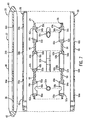
Fig. 3 is a side elevation view of a first embodiment of a level in accordance with the invention, having a frame and luminescent side covers that retain the vials in engagement with the frame; -
Fig. 4 is an enlarged partial elevation view with reference to line 4--4 ofFig. 3 , showing the level in a darkened environment; -
Fig. 5 is a sectional view taken alongline 5--5 ofFig. 3 ; -
Fig. 6 is a sectional view taken alongline 6--6 ofFig. 3 ; -
Fig. 7 is a an exploded section view of the level ofFigs. 3 through 6 ; -
Fig. 8 is a partial elevation view of a second embodiment of a level in accordance with the invention, incorporating a luminescent individual vial cover arrangement; and -
Fig. 9 is a sectional view taken alongline 9--9 ofFig. 8 . -
Figs. 1 and 2 show a prior art box beam-type level 10 that has a three-sided opening 12 that receives ablock vial 14, and aluminescent insert 16 disposed below one side of thevial 14. In low light conditions, light from theinsert 16 is directed toward and through thevial 14, as is represented schematically bylines 18 that project upwardly from theinsert 16 inFig. 2 . It can be appreciated that having only one side of thevial 14 illuminated does not provide much more visibility to the vial than conventional, non-illuminated levels. Furthermore, theluminescent insert 16 is an additional piece that must be separately fabricated, thus requiring additional tooling for theluminescent insert 16 and also requiring modification of the surrounding parts of the level to accompany theinsert 16. Furthermore, theinsert 16 must be assembled into the level, which increase the assembly time and cost of the level. -
Figs. 3-7 show a first embodiment of a tool, such as alevel 20, made in accordance with the invention.Level 20 includes aframe 22, a pair ofside cover inserts outer casing members vials frame 22 and retained withinopenings level 20 is in accordance with the prior art, such as a level available from Johnson Level & Tool Mfg. Co., Inc. of Mequon, Wisconsin under its designation #931-9RE. -
Vials openings web 36 offrame 20, to position eachvial level frame 22.Vial 32a extends transversely to the longitudinal axis offrame 22,vial 32b extends parallel to the longitudinal axis offrame 22, andvial 32c extends at a 45° angle diagonally relative to the longitudinal axis offrame 22. In this manner,vial 32a is a plumb vial,vial 32b is a level vial, andvial 32c is a vial that provides a reading relative to a plane of 45° between plumb and level. - In accordance with conventional construction,
frame 22 includes a pair offlanges 38 between whichweb 36 extends, and the outer surface of eachflange 38 provides a gauging surface forlevel 20.Frame 22 further includes a pair ofend sections 40 that extend betweenflanges 38 at the opposite ends ofweb 36. -
Openings web 36 are defined by edges that are formed with opposed notches within which the ends ofvials vial respective opening vial - Side cover inserts 24 and 26 are adapted for placement on opposite sides of
web 36, and are configured to retainvials frame web 36.Side cover insert 24 includes a series ofretainer sections respective openings Intermediate connector sections 46 extend between andinterconnect retainer sections Retainer section 42a includes a pair ofnotches 48a on opposite sides ofopening 44a that are configured to engage the ends ofvial 32a: Similarly,retainer section 42b includes a pair ofnotches 48b adapted to engage the ends ofvial 32b, andretainer section 42c includes a pair ofnotches 48c adapted to engage the ends ofvial 32c. The inside facing surface of eachretainer section peripheral grooves -
Side cover insert 26 is formed similarly toside cover insert 24, includingretainer sections respective openings connector sections 56 thatinterconnect retainer sections Notches retainer sections vials Retainer sections peripheral ribs respective grooves side cover insert 24, so as to fix the position of side cover inserts 24, 26 relative to each other on either side ofweb 36. -
Openings vials respective notches openings respective vials respective vials respective openings - Outer
side casing members web 36.Outer casing member 28 includes anouter wall 62 within whichopenings vial retainer sections outer casing member 30 includes anouter wall 66 within whichopenings vial retainer sections cover insert 26. Side cover inserts 24, 26 andouter casing members frame 22 in any conventional manner, such as by sonic welding, snap-fit adhesive or the like. Side cover inserts 24, 26 are preferably formed of a thermoplastic material such as polystyrene in an injection molding process, although it is understood that any other satisfactory thermoplastic material such as ABS, crystal styrene, acrylic, amorphous nylon, and transparent ABS may be employed, and that other forming methods may also be used. Similarly,outer casing members - In accordance with the present invention, side cover inserts 24, 26 are formed of a material that is luminescent, such that cover inserts 24, 26 have a glow in the dark feature. Such luminescence of cover inserts 24, 26 may be provided in any satisfactory manner, such as by incorporating a luminescent agent into the material of side cover inserts 24, 26. In a representative embodiment, side cover inserts 24, 26 are formed of a pigment free thermoplastic material such as polystyrene, and a luminescent agent in the form of a LUMI-NOVA® pigment is incorporated into the pigment free thermoplastic material of side cover inserts 24, 26. The LUMI-NOVA® luminescent agent is available from United Mineral and Chemical Corporation of Lyndhurst, New Jersey, and is described in
U.S. Patent 5,686,022 . The luminescent agent is a phosphorescent phosphor material that absorbs energy from light and then returns the absorbed energy in the form of luminescence in a darkened environment. In a representative embodiment, the luminescent agent is incorporated into the thermoplastic material of cover inserts 24, 26 in a ratio of approximately one (1) part luminescent agent to thirty three (33) parts thermoplastic material. While the LUMI-NOVA® luminescent agent has been found to provide a highly satisfactory luminescent characteristic, it is understood that any other type of luminescent agent may be employed in side cover inserts 24, 26. - As shown in
Fig. 4 ,level 20 is well suited for use in a dark environment, which is illustrated generally at 64. Whenlevel 20 is positioned in thedark environment 64, the luminescence of the material of side cover inserts 24, 26, and in particular the exposedretainer sections vial 32b as illustrated inFig. 4 , to illuminate the vial and to enable the bubble of the vial, shown at 66, to be clearly visible withindark environment 64.Lines 68 represent the emission of light into thespace surrounding vial 32b fromretainer sections vial 32b as well as the surfaces ofvial 32b are illuminated, and the translucence ofvial 32b functions to enable light to pass therethrough so as to enable light to pass intovial 32b and thereby enhance visibility ofbubble 66. - The luminescent agent incorporated into the material of side cover inserts 24, 26 preferably provides luminescence for an extended period of time without recharging by exposure to an external light source, to enable
level 20 to be used indarkened environment 64 for an extended period of time. -
Casing members vial retainer sections level 20 is in low light conditions, to quickly draw the user's eyes to thebubble vials - While
level 20 is illustrated as being a torpedo-type level having a certain construction, it is understood that the luminescent feature of the present invention may be employed in other types of torpedo levels and in any other type of level construction. Another example is illustrated inFigs. 8 and 9 , which illustrate separate vial covers on opposite sides of the web of the level frame, which engage the vial ends and retain the vial in engagement with the level frame. In this embodiment, alevel 70 includes aframe 72 having aweb 74 and a pair offlanges 76. A bubble vial, such as 78, extends across an opening inweb 74, and the ends ofvial 76 are received within notches defined by the edges of the opening, in a known manner. Vial covers orholders web 74, and include notches within which the ends ofvial 76 are received. With this arrangement, vial covers 78, 80 function to retainvial 76 in engagement withweb 74 offrame 72. Vial covers 78, 80 definerespective openings vial 76 extends acrossopenings vial 76, to define open space between the vial surfaces and the surfaces of vial covers 78, 80 that defineopenings vial 76, as shown at 86, whenlevel 70 is placed in a darkened environment. - Representatively, vial covers 78 may have a construction such as is illustrated in
Grosz U.S. Patent 4,996,777 although it is understood that any other satisfactory type of vial holder or retainer construction may be employed. - While the invention has been shown and described with respect to certain embodiments, it is understood that other variations and alternatives are possible and are contemplated as being within the scope of the present invention. For example, and without limitation, the luminescent material that surrounds and illuminates the bubble vial has been shown and described in connection with a level. It is understood, however, that this feature may also be incorporated in any other type of tool that utilizes a bubble vial, especially in an application in which the bubble vial extends through or across a space. In any tool of this type, the material within which the space is formed includes a luminescent characteristic, so that light is emitted toward and onto the vial when the tool is used in a darkened environment. In addition, while the invention has been described with respect to the luminescent material being dispersed throughout the material of the vial holder or vial holding section, it is also understood that luminescent material may simply be applied to the surfaces that face the vial, which provides the same type of illumination in that light is emitted toward and onto the vial in a darkened environment In the embodiment of
Figs. 1-7 , while the entirety of vial cover inserts 24, 26 is described as being formed of a material with a luminescent characteristic, it is understood that the luminescent material may only be incorporated in the vial retaining sections and not in the sections that connect the vial retaining sections. In addition, in a separate vial cover embodiment such as inFigs. 8 and 9 , separate outer vial covers may be formed of a non-luminescent material and separate inner vial retaining sections may be surrounded by the outer sections and define the surfaces that face the vial and engage the ends of the vial. This type of construction avoids forming the entire vial holder of luminescent material, but rather uses luminescent material only in the areas that surround and face the vial. In a wood level, the luminescent material may be incorporated into the plastic material of the vial holders, which are located inside of the lenses through which the vials are viewed. - It can thus be appreciated that the present invention contemplates incorporating luminescent material into existing structure that is utilized to secure a vial in place in a tool. This avoids the need for a separate luminescent member, as in the prior art, so that existing construction can be employed while simply altering the material of construction so as to minimize costs of incorporating the vial illumination feature of the present invention into a tool.
Claims (7)
- A tool (20), comprising:a body having an opening (34a, 34b, 34c);a bubble vial (32a, 32b, 32c) extending across the opening (34a, 34b, 34c), wherein the vial (32a, 32b, 32c) defines one or more exterior surfaces; anda vial retainer arrangement (24,26) for securing the bubble vial (34a, 34b, 34c) in position relative to the body,characterised in that the vial retainer (24,26) arrangement includes one or more vial retainer member (24,26) separate from and engageable between the vial (32a, 32b, 32c) and the body for securing the vial in position on the body, the one or more vial retainer members (24,26) defining one or more inwardly facing surfaces which extend around the vial;in that the vial (32a, 32b, 32c) is oriented relative to the body and the vial retainer members (24,26) such that the one or more exterior surfaces of the vial (32a, 32b, 32c) are located inwardly of the one or more inwardly facing surfaces (42a, 42b, 42c, 52a, 52b, 52c) of the vial retainer members (24,26), wherein the one or more inwardly facing surfaces (42a, 42b, 42c, 52a, 52b, 52c) of the vial retainer members (24,26) face towards the vial and wherein the one or more inwardly facing surfaces (42a, 42b, 42c, 52a, 52b, 52c) of the vial retainer members (24,26) and the one or more exterior surfaces of the vial (32a, 32b, 32c) are configured such that an open space (44a, 44b, 44c, 54a, 54b, 54c) is defined between the one or more exterior surfaces of the vial and the one or more inwardly facing surfaces of the vial retainer members; andin that the one or more inwardly facing surfaces of the vial retainer members (24,26) are formed of a luminescent material, the inwardly facing surfaces of the luminescent material being exposed to said open space (44a, 44b, 44c, 54a, 54b, 54c) such that the luminescent material emits light from said one or more inwardly facing surfaces (32a, 32b, 32c) through the open space and onto the one or more exterior surfaces of the vial (32a, 32b, 32c) to illuminate the vial around so as to provide visibility of the vial when the tool is placed in a darkened environment.
- A tool of claim 1, wherein the tool comprises a level (20) having a frame (22), and wherein the one or more vial retainer members (24,26) engage the frame (22) and the vial (32a, 32b, 32c) to maintain the vial in a predetermined position relative to the frame (22).
- A tool of claim 1 or claim 2, wherein the luminescent material comprises the material from which the one or more vial retainer members (24,26) are formed.
- A tool according to any of the preceding claims, wherein the one or more vial retainer members (24,26) comprise a pair of vial retainers (24,26) located one on either side of a web (36) defined by the frame (22) of the level (20), wherein the pair of vial retainers (24,26) functions to maintain the vial in engagement with the web (26) of the frame (22).
- A tool of claim 2, wherein the luminescent material comprises a thermoplastic material having a phosphorescent phosphor material dispersed therewithin.
- A tool according to claim 1, wherein the vial retaining members (24,26) are thermoplastic, and wherein luminescent material is dispersed throughout the material of the retaining members (24,26).
- A method of illuminating a vial of a tool according to any of the preceding claims, comprising the steps of positioning the vial (32a, 32b, 32c) within
an opening (34a, 34b, 24c) formed in a body associated with the tool (20) such that the one or more exterior surfaces of the vial (32a, 32b, 32c) are located inwardly of one or more inwardly facing surfaces of the body (20) that define the opening (34a, 34b, 34c), an open space (44a, 44b, 44c, 54a, 54b, 54c) being defined between the one or more exterior surfaces of the vial (32a, 32b, 32c) and the one or more inwardly facing surfaces of the body (20) that define the opening, and placing between the one or more inwardly facing surfaces of the body (20) and the vial one or more vial retainer members (24,26), which retainer members include luminescent material, are separate from and are engageable with the body (20) and with the vial (32a, 32b, 32c), and extend around the vial (32a, 32b, 32c) so as to maintain the vial in position within the opening in the body of the tool, the luminescent material emitting light through the open space (44a, 44b, 44c, 54a, 54b, 54c) and onto the one or more exterior surfaces of the vial so as to illuminate the vial when the tool is placed in a darkened environment.
Applications Claiming Priority (3)
| Application Number | Priority Date | Filing Date | Title |
|---|---|---|---|
| US10/228,579 US7024781B1 (en) | 2002-08-27 | 2002-08-27 | Vial illumination feature for a tool such as a level |
| US228579 | 2002-08-27 | ||
| PCT/US2003/018054 WO2004020944A1 (en) | 2002-08-27 | 2003-06-06 | Vial illumination for a tool |
Publications (2)
| Publication Number | Publication Date |
|---|---|
| EP1532423A1 EP1532423A1 (en) | 2005-05-25 |
| EP1532423B1 true EP1532423B1 (en) | 2010-08-11 |
Family
ID=31976061
Family Applications (1)
| Application Number | Title | Priority Date | Filing Date |
|---|---|---|---|
| EP03791558A Expired - Lifetime EP1532423B1 (en) | 2002-08-27 | 2003-06-06 | Vial illumination for a tool |
Country Status (8)
| Country | Link |
|---|---|
| US (1) | US7024781B1 (en) |
| EP (1) | EP1532423B1 (en) |
| CN (1) | CN1678882B (en) |
| AT (1) | ATE477470T1 (en) |
| AU (1) | AU2003251420A1 (en) |
| CA (1) | CA2496387C (en) |
| DE (1) | DE60333760D1 (en) |
| WO (1) | WO2004020944A1 (en) |
Families Citing this family (21)
| Publication number | Priority date | Publication date | Assignee | Title |
|---|---|---|---|---|
| DE202004006643U1 (en) * | 2004-03-12 | 2005-07-21 | Stabila-Meßgeräte Gustav Ullrich GmbH | Spirit level with an injection molded body that incorporates thermoplastic strengthening inserts which are at least partially enclosed by the injection molding process |
| US7959827B2 (en) * | 2007-12-12 | 2011-06-14 | General Electric Company | Persistent phosphor |
| US8003012B2 (en) * | 2007-01-17 | 2011-08-23 | General Electric Company | Method for producing a palette of colors for persistent phosphors and phosphors made by same |
| US20080171229A1 (en) * | 2007-01-17 | 2008-07-17 | General Electric Company | Method of producing a palette of colors for persistent phosphors and phosphors made by same |
| US8333907B2 (en) | 2007-01-17 | 2012-12-18 | Utc Fire & Security Corporation | Articles using persistent phosphors |
| WO2008144545A2 (en) * | 2007-05-18 | 2008-11-27 | Allemand James S | Composite level tool |
| US8545723B2 (en) * | 2007-12-12 | 2013-10-01 | General Electric Company | Persistent phosphor |
| US8329060B2 (en) * | 2008-10-22 | 2012-12-11 | General Electric Company | Blue-green and green phosphors for lighting applications |
| US8703016B2 (en) | 2008-10-22 | 2014-04-22 | General Electric Company | Phosphor materials and related devices |
| US20110005091A1 (en) * | 2009-06-29 | 2011-01-13 | Pedersen Dale A | Level lite |
| US8522446B1 (en) * | 2009-12-08 | 2013-09-03 | Karl E. Staudt | Level assembly |
| US20110147661A1 (en) * | 2009-12-21 | 2011-06-23 | Sam Joseph Camardello | Novel aluminosilicate based blue persistent phosphors |
| CA2797106C (en) | 2010-05-03 | 2016-11-08 | James S. Allemand | Lighted level tool |
| AT515707B1 (en) * | 2014-04-25 | 2022-04-15 | Sola Messwerkzeuge Gmbh | Dragonfly for a spirit level |
| CN105333862B (en) * | 2014-08-08 | 2018-05-25 | 梅特勒-托利多仪器(上海)有限公司 | Measure the device and method of air level bubble position and the air level comprising the equipment |
| CN107076556B (en) | 2014-11-13 | 2021-08-03 | 米沃奇电动工具公司 | level |
| US20180283581A1 (en) * | 2017-03-23 | 2018-10-04 | Jose Ramirez | Interlocking Axial Pipe Fitting Squares |
| US11105625B1 (en) * | 2018-05-29 | 2021-08-31 | William Clifton Harrison | Multi-use level that illuminates when level |
| WO2020150484A1 (en) | 2019-01-17 | 2020-07-23 | Milwaukee Electric Tool Corporation | Two datum vial mounting system and method |
| US11193764B2 (en) | 2019-01-17 | 2021-12-07 | Milwaukee Electric Tool Corporation | Two datum vial mounting system and method |
| US11828595B2 (en) * | 2021-12-12 | 2023-11-28 | Thomas Costello | Instrument for determining level or plumb orientations |
Family Cites Families (33)
| Publication number | Priority date | Publication date | Assignee | Title |
|---|---|---|---|---|
| US674107A (en) * | 1900-04-04 | 1901-05-14 | Justus A Traut | Level-glass. |
| US1318162A (en) | 1919-06-16 | 1919-10-07 | Ernest J Loring | Luminous level. |
| US2344241A (en) * | 1942-01-28 | 1944-03-14 | Bausch & Lomb | Illuminated bubble level |
| US2362872A (en) * | 1943-03-06 | 1944-11-14 | Rca Corp | Spirit device |
| US2813349A (en) * | 1953-01-02 | 1957-11-19 | Creative Plastics Corp | Level |
| US2877561A (en) * | 1955-05-16 | 1959-03-17 | William L Morse | Angular position indicator |
| FR1247106A (en) | 1960-01-27 | 1960-11-25 | Antichoc | Luminescent vial for water levels |
| GB1001771A (en) * | 1963-05-01 | 1965-08-18 | Saunders Roe & Nuclear Entpr | Improvements in or relating to the illumination of levelling bubbles |
| GB1161065A (en) * | 1966-01-20 | 1969-08-13 | Stanley Horace Frederick Sarl | Improvements in or relating to Surveying Instruments. |
| FR1500836A (en) | 1966-05-13 | 1967-11-10 | Saint Gobain Techn Nouvelles | Improvements to horizontal direction tracking devices |
| US3568287A (en) | 1969-01-24 | 1971-03-09 | Albert J Balon | Method of making connector and tube assembly |
| US3738015A (en) * | 1970-05-11 | 1973-06-12 | Stanley Works | Snap-in vial retainers |
| US3766657A (en) * | 1970-10-16 | 1973-10-23 | Hopkins Mf Corp | Trailer level indicating device |
| US4103430A (en) * | 1977-08-31 | 1978-08-01 | Schrader Joseph F | Viewing device for a bubble level |
| DE2754030A1 (en) | 1977-12-05 | 1979-06-07 | Hans Faass | Spirit level for single operator in poor light - has integral light sources and voltage supplies for bubbles with light source in discharge tube |
| US4164077A (en) * | 1978-07-07 | 1979-08-14 | Hopkins Manufacturing Corporation | Level indicating devices |
| US4332046A (en) * | 1979-06-05 | 1982-06-01 | Foley Clifford T | Combined hammer and level |
| CH637765A5 (en) * | 1980-10-17 | 1983-08-15 | Valinor Sa | DEVICE FOR LOCATING THE DEGREE OF TILT OF THE AXIS OF A TUBULAR OBJECT. |
| US4407075A (en) * | 1981-12-03 | 1983-10-04 | Louis Rains | Illuminated spirit vial and level |
| US4610094A (en) * | 1985-09-19 | 1986-09-09 | George Robson | Level |
| US4912854A (en) * | 1988-10-19 | 1990-04-03 | Weadon Joseph P | Cross vial liquid bubble illuminated level |
| US4932133A (en) * | 1989-06-05 | 1990-06-12 | Upward, Inc. | Post-avalanche aid device |
| US4996777A (en) * | 1989-08-09 | 1991-03-05 | Johnson Level & Tool Mfg. Co., Inc. | Snap-in level vial cover |
| US5033199A (en) * | 1989-10-11 | 1991-07-23 | The Stanley Works | Level vial holder assembly |
| GB9001377D0 (en) | 1990-01-20 | 1990-03-21 | Wilkins Andre P | Tamper evident container/carton |
| GB2248938A (en) * | 1990-10-17 | 1992-04-22 | Lee Reginald Webster | Level |
| GB2250091A (en) | 1990-11-21 | 1992-05-27 | Peter Werbowy | Spirit levels |
| US5105549A (en) * | 1991-06-14 | 1992-04-21 | Johnson Level & Tool Mfg. Co., Inc. | Level with top-reading magnification |
| US5199177A (en) * | 1992-05-14 | 1993-04-06 | Stanley Tools, A Division Of The Stanley Works | Level |
| CA2107441A1 (en) * | 1993-04-02 | 1994-10-03 | John G. Baker | Level vial assembly |
| JP3456553B2 (en) * | 1994-11-01 | 2003-10-14 | 根本特殊化学株式会社 | Phosphorescent phosphor |
| US6148530A (en) * | 1998-10-16 | 2000-11-21 | Great Neck Saw Manufacturers, Inc. | Level with snap action vial holder |
| US6760975B1 (en) * | 2002-10-01 | 2004-07-13 | Great Neck Saw Manufacturers, Inc. | Vial holding level |
-
2002
- 2002-08-27 US US10/228,579 patent/US7024781B1/en not_active Expired - Lifetime
-
2003
- 2003-06-06 DE DE60333760T patent/DE60333760D1/en not_active Expired - Lifetime
- 2003-06-06 WO PCT/US2003/018054 patent/WO2004020944A1/en not_active Ceased
- 2003-06-06 EP EP03791558A patent/EP1532423B1/en not_active Expired - Lifetime
- 2003-06-06 AT AT03791558T patent/ATE477470T1/en not_active IP Right Cessation
- 2003-06-06 CN CN038202247A patent/CN1678882B/en not_active Expired - Lifetime
- 2003-06-06 CA CA2496387A patent/CA2496387C/en not_active Expired - Lifetime
- 2003-06-06 AU AU2003251420A patent/AU2003251420A1/en not_active Abandoned
Also Published As
| Publication number | Publication date |
|---|---|
| CN1678882B (en) | 2010-12-15 |
| CA2496387C (en) | 2012-02-07 |
| US7024781B1 (en) | 2006-04-11 |
| WO2004020944A1 (en) | 2004-03-11 |
| ATE477470T1 (en) | 2010-08-15 |
| CN1678882A (en) | 2005-10-05 |
| AU2003251420A1 (en) | 2004-03-19 |
| DE60333760D1 (en) | 2010-09-23 |
| CA2496387A1 (en) | 2004-03-11 |
| EP1532423A1 (en) | 2005-05-25 |
Similar Documents
| Publication | Publication Date | Title |
|---|---|---|
| CA2496387C (en) | Vial illumination for a tool | |
| TWI727644B (en) | Level | |
| AU2011248348B2 (en) | Lighted level tool | |
| EP1700084B1 (en) | Pocket level | |
| US4407075A (en) | Illuminated spirit vial and level | |
| US5522146A (en) | Level marker | |
| KR910010486A (en) | Disc cartridge | |
| GT199800004S (en) | WRITING INSTRUMENT COVER. (CASE 2). | |
| ES2145624T3 (en) | UREA BASED TABLETS MARKED WITH ISOTOPES. | |
| DE602004031150D1 (en) | MARKING ASSEMBLY FOR ELECTRONIC ARTICLE ASSURANCE | |
| US4862595A (en) | Extension level | |
| CN213148726U (en) | spectrometer | |
| JP2002373512A (en) | Electronic device housing | |
| MY140295A (en) | Photographic processing agent cartridge | |
| KR200282159Y1 (en) | a cellular case | |
| IL137195A (en) | Wall-mounting enclosure for electrical components | |
| JP2804450B2 (en) | Photoelectric sensor | |
| KR200245328Y1 (en) | collection box | |
| KR860001717Y1 (en) | Rice canister with door on transparent window | |
| KR840000828A (en) | Electronic watch assembly | |
| JPH0399226A (en) | Air hole for vehicle instrument | |
| GB2329470A (en) | Compass disc having a map | |
| US20020092459A1 (en) | Indicator light collector | |
| JPH0618309A (en) | Flowmeter with transmitter | |
| KR970000920A (en) | Glove box structure |
Legal Events
| Date | Code | Title | Description |
|---|---|---|---|
| PUAI | Public reference made under article 153(3) epc to a published international application that has entered the european phase |
Free format text: ORIGINAL CODE: 0009012 |
|
| 17P | Request for examination filed |
Effective date: 20050301 |
|
| AK | Designated contracting states |
Kind code of ref document: A1 Designated state(s): AT BE BG CH CY CZ DE DK EE ES FI FR GB GR HU IE IT LI LU MC NL PT RO SE SI SK TR |
|
| AX | Request for extension of the european patent |
Extension state: AL LT LV MK |
|
| DAX | Request for extension of the european patent (deleted) | ||
| 17Q | First examination report despatched |
Effective date: 20080204 |
|
| GRAP | Despatch of communication of intention to grant a patent |
Free format text: ORIGINAL CODE: EPIDOSNIGR1 |
|
| GRAS | Grant fee paid |
Free format text: ORIGINAL CODE: EPIDOSNIGR3 |
|
| GRAA | (expected) grant |
Free format text: ORIGINAL CODE: 0009210 |
|
| AK | Designated contracting states |
Kind code of ref document: B1 Designated state(s): AT BE BG CH CY CZ DE DK EE ES FI FR GB GR HU IE IT LI LU MC NL PT RO SE SI SK TR |
|
| REG | Reference to a national code |
Ref country code: GB Ref legal event code: FG4D |
|
| REG | Reference to a national code |
Ref country code: CH Ref legal event code: EP |
|
| REG | Reference to a national code |
Ref country code: IE Ref legal event code: FG4D |
|
| REF | Corresponds to: |
Ref document number: 60333760 Country of ref document: DE Date of ref document: 20100923 Kind code of ref document: P |
|
| REG | Reference to a national code |
Ref country code: NL Ref legal event code: VDEP Effective date: 20100811 |
|
| PG25 | Lapsed in a contracting state [announced via postgrant information from national office to epo] |
Ref country code: FI Free format text: LAPSE BECAUSE OF FAILURE TO SUBMIT A TRANSLATION OF THE DESCRIPTION OR TO PAY THE FEE WITHIN THE PRESCRIBED TIME-LIMIT Effective date: 20100811 Ref country code: NL Free format text: LAPSE BECAUSE OF FAILURE TO SUBMIT A TRANSLATION OF THE DESCRIPTION OR TO PAY THE FEE WITHIN THE PRESCRIBED TIME-LIMIT Effective date: 20100811 Ref country code: AT Free format text: LAPSE BECAUSE OF FAILURE TO SUBMIT A TRANSLATION OF THE DESCRIPTION OR TO PAY THE FEE WITHIN THE PRESCRIBED TIME-LIMIT Effective date: 20100811 |
|
| PG25 | Lapsed in a contracting state [announced via postgrant information from national office to epo] |
Ref country code: SI Free format text: LAPSE BECAUSE OF FAILURE TO SUBMIT A TRANSLATION OF THE DESCRIPTION OR TO PAY THE FEE WITHIN THE PRESCRIBED TIME-LIMIT Effective date: 20100811 Ref country code: PT Free format text: LAPSE BECAUSE OF FAILURE TO SUBMIT A TRANSLATION OF THE DESCRIPTION OR TO PAY THE FEE WITHIN THE PRESCRIBED TIME-LIMIT Effective date: 20101213 Ref country code: BG Free format text: LAPSE BECAUSE OF FAILURE TO SUBMIT A TRANSLATION OF THE DESCRIPTION OR TO PAY THE FEE WITHIN THE PRESCRIBED TIME-LIMIT Effective date: 20101111 Ref country code: CY Free format text: LAPSE BECAUSE OF FAILURE TO SUBMIT A TRANSLATION OF THE DESCRIPTION OR TO PAY THE FEE WITHIN THE PRESCRIBED TIME-LIMIT Effective date: 20100811 |
|
| PG25 | Lapsed in a contracting state [announced via postgrant information from national office to epo] |
Ref country code: SE Free format text: LAPSE BECAUSE OF FAILURE TO SUBMIT A TRANSLATION OF THE DESCRIPTION OR TO PAY THE FEE WITHIN THE PRESCRIBED TIME-LIMIT Effective date: 20100811 Ref country code: BE Free format text: LAPSE BECAUSE OF FAILURE TO SUBMIT A TRANSLATION OF THE DESCRIPTION OR TO PAY THE FEE WITHIN THE PRESCRIBED TIME-LIMIT Effective date: 20100811 Ref country code: GR Free format text: LAPSE BECAUSE OF FAILURE TO SUBMIT A TRANSLATION OF THE DESCRIPTION OR TO PAY THE FEE WITHIN THE PRESCRIBED TIME-LIMIT Effective date: 20101112 |
|
| PG25 | Lapsed in a contracting state [announced via postgrant information from national office to epo] |
Ref country code: DK Free format text: LAPSE BECAUSE OF FAILURE TO SUBMIT A TRANSLATION OF THE DESCRIPTION OR TO PAY THE FEE WITHIN THE PRESCRIBED TIME-LIMIT Effective date: 20100811 |
|
| PG25 | Lapsed in a contracting state [announced via postgrant information from national office to epo] |
Ref country code: CZ Free format text: LAPSE BECAUSE OF FAILURE TO SUBMIT A TRANSLATION OF THE DESCRIPTION OR TO PAY THE FEE WITHIN THE PRESCRIBED TIME-LIMIT Effective date: 20100811 Ref country code: RO Free format text: LAPSE BECAUSE OF FAILURE TO SUBMIT A TRANSLATION OF THE DESCRIPTION OR TO PAY THE FEE WITHIN THE PRESCRIBED TIME-LIMIT Effective date: 20100811 Ref country code: EE Free format text: LAPSE BECAUSE OF FAILURE TO SUBMIT A TRANSLATION OF THE DESCRIPTION OR TO PAY THE FEE WITHIN THE PRESCRIBED TIME-LIMIT Effective date: 20100811 Ref country code: SK Free format text: LAPSE BECAUSE OF FAILURE TO SUBMIT A TRANSLATION OF THE DESCRIPTION OR TO PAY THE FEE WITHIN THE PRESCRIBED TIME-LIMIT Effective date: 20100811 Ref country code: IT Free format text: LAPSE BECAUSE OF FAILURE TO SUBMIT A TRANSLATION OF THE DESCRIPTION OR TO PAY THE FEE WITHIN THE PRESCRIBED TIME-LIMIT Effective date: 20100811 |
|
| PLBE | No opposition filed within time limit |
Free format text: ORIGINAL CODE: 0009261 |
|
| STAA | Information on the status of an ep patent application or granted ep patent |
Free format text: STATUS: NO OPPOSITION FILED WITHIN TIME LIMIT |
|
| PG25 | Lapsed in a contracting state [announced via postgrant information from national office to epo] |
Ref country code: ES Free format text: LAPSE BECAUSE OF FAILURE TO SUBMIT A TRANSLATION OF THE DESCRIPTION OR TO PAY THE FEE WITHIN THE PRESCRIBED TIME-LIMIT Effective date: 20101122 |
|
| 26N | No opposition filed |
Effective date: 20110512 |
|
| REG | Reference to a national code |
Ref country code: DE Ref legal event code: R097 Ref document number: 60333760 Country of ref document: DE Effective date: 20110512 |
|
| REG | Reference to a national code |
Ref country code: CH Ref legal event code: PL |
|
| GBPC | Gb: european patent ceased through non-payment of renewal fee |
Effective date: 20110606 |
|
| REG | Reference to a national code |
Ref country code: FR Ref legal event code: ST Effective date: 20120229 |
|
| REG | Reference to a national code |
Ref country code: IE Ref legal event code: MM4A |
|
| PG25 | Lapsed in a contracting state [announced via postgrant information from national office to epo] |
Ref country code: FR Free format text: LAPSE BECAUSE OF NON-PAYMENT OF DUE FEES Effective date: 20110630 Ref country code: IE Free format text: LAPSE BECAUSE OF NON-PAYMENT OF DUE FEES Effective date: 20110606 Ref country code: CH Free format text: LAPSE BECAUSE OF NON-PAYMENT OF DUE FEES Effective date: 20110630 Ref country code: LI Free format text: LAPSE BECAUSE OF NON-PAYMENT OF DUE FEES Effective date: 20110630 |
|
| PG25 | Lapsed in a contracting state [announced via postgrant information from national office to epo] |
Ref country code: GB Free format text: LAPSE BECAUSE OF NON-PAYMENT OF DUE FEES Effective date: 20110606 |
|
| PG25 | Lapsed in a contracting state [announced via postgrant information from national office to epo] |
Ref country code: MC Free format text: LAPSE BECAUSE OF NON-PAYMENT OF DUE FEES Effective date: 20110630 |
|
| PG25 | Lapsed in a contracting state [announced via postgrant information from national office to epo] |
Ref country code: LU Free format text: LAPSE BECAUSE OF NON-PAYMENT OF DUE FEES Effective date: 20110606 |
|
| PG25 | Lapsed in a contracting state [announced via postgrant information from national office to epo] |
Ref country code: TR Free format text: LAPSE BECAUSE OF FAILURE TO SUBMIT A TRANSLATION OF THE DESCRIPTION OR TO PAY THE FEE WITHIN THE PRESCRIBED TIME-LIMIT Effective date: 20100811 |
|
| PG25 | Lapsed in a contracting state [announced via postgrant information from national office to epo] |
Ref country code: HU Free format text: LAPSE BECAUSE OF FAILURE TO SUBMIT A TRANSLATION OF THE DESCRIPTION OR TO PAY THE FEE WITHIN THE PRESCRIBED TIME-LIMIT Effective date: 20100811 |
|
| PGFP | Annual fee paid to national office [announced via postgrant information from national office to epo] |
Ref country code: DE Payment date: 20220414 Year of fee payment: 20 |
|
| REG | Reference to a national code |
Ref country code: DE Ref legal event code: R071 Ref document number: 60333760 Country of ref document: DE |