EP1532391B2 - ISOLIERPLATTE FüR ZUFUHRKANAL - Google Patents
ISOLIERPLATTE FüR ZUFUHRKANAL Download PDFInfo
- Publication number
- EP1532391B2 EP1532391B2 EP03760735.5A EP03760735A EP1532391B2 EP 1532391 B2 EP1532391 B2 EP 1532391B2 EP 03760735 A EP03760735 A EP 03760735A EP 1532391 B2 EP1532391 B2 EP 1532391B2
- Authority
- EP
- European Patent Office
- Prior art keywords
- duct
- section
- angle
- panel
- cutting
- Prior art date
- Legal status (The legal status is an assumption and is not a legal conclusion. Google has not performed a legal analysis and makes no representation as to the accuracy of the status listed.)
- Expired - Lifetime
Links
- 238000009413 insulation Methods 0.000 title description 12
- 238000009826 distribution Methods 0.000 claims description 14
- 239000011490 mineral wool Substances 0.000 claims description 7
- 229910052782 aluminium Inorganic materials 0.000 claims description 6
- XAGFODPZIPBFFR-UHFFFAOYSA-N aluminium Chemical compound [Al] XAGFODPZIPBFFR-UHFFFAOYSA-N 0.000 claims description 6
- 238000005520 cutting process Methods 0.000 description 55
- 238000000034 method Methods 0.000 description 35
- 238000004519 manufacturing process Methods 0.000 description 14
- 230000001143 conditioned effect Effects 0.000 description 11
- 238000011144 upstream manufacturing Methods 0.000 description 9
- 238000005259 measurement Methods 0.000 description 8
- 238000007789 sealing Methods 0.000 description 8
- 230000004048 modification Effects 0.000 description 7
- 238000012986 modification Methods 0.000 description 7
- 239000011491 glass wool Substances 0.000 description 6
- 229910052751 metal Inorganic materials 0.000 description 5
- 239000002184 metal Substances 0.000 description 5
- 230000000295 complement effect Effects 0.000 description 4
- 239000002390 adhesive tape Substances 0.000 description 3
- 239000003292 glue Substances 0.000 description 3
- 238000000926 separation method Methods 0.000 description 3
- 230000001154 acute effect Effects 0.000 description 2
- 230000032798 delamination Effects 0.000 description 2
- 238000004378 air conditioning Methods 0.000 description 1
- 239000011324 bead Substances 0.000 description 1
- 238000005452 bending Methods 0.000 description 1
- 230000015572 biosynthetic process Effects 0.000 description 1
- 230000003750 conditioning effect Effects 0.000 description 1
- 238000010276 construction Methods 0.000 description 1
- 238000010586 diagram Methods 0.000 description 1
- 239000000428 dust Substances 0.000 description 1
- 239000004744 fabric Substances 0.000 description 1
- 239000011152 fibreglass Substances 0.000 description 1
- 239000010408 film Substances 0.000 description 1
- 238000009434 installation Methods 0.000 description 1
- 239000011810 insulating material Substances 0.000 description 1
- 238000005304 joining Methods 0.000 description 1
- 238000012423 maintenance Methods 0.000 description 1
- 239000000463 material Substances 0.000 description 1
- 239000011505 plaster Substances 0.000 description 1
- 230000000750 progressive effect Effects 0.000 description 1
- 238000010079 rubber tapping Methods 0.000 description 1
- 239000007787 solid Substances 0.000 description 1
- 239000010409 thin film Substances 0.000 description 1
Images


Classifications
-
- F—MECHANICAL ENGINEERING; LIGHTING; HEATING; WEAPONS; BLASTING
- F24—HEATING; RANGES; VENTILATING
- F24F—AIR-CONDITIONING; AIR-HUMIDIFICATION; VENTILATION; USE OF AIR CURRENTS FOR SCREENING
- F24F13/00—Details common to, or for air-conditioning, air-humidification, ventilation or use of air currents for screening
- F24F13/02—Ducting arrangements
- F24F13/0263—Insulation for air ducts
-
- F—MECHANICAL ENGINEERING; LIGHTING; HEATING; WEAPONS; BLASTING
- F16—ENGINEERING ELEMENTS AND UNITS; GENERAL MEASURES FOR PRODUCING AND MAINTAINING EFFECTIVE FUNCTIONING OF MACHINES OR INSTALLATIONS; THERMAL INSULATION IN GENERAL
- F16L—PIPES; JOINTS OR FITTINGS FOR PIPES; SUPPORTS FOR PIPES, CABLES OR PROTECTIVE TUBING; MEANS FOR THERMAL INSULATION IN GENERAL
- F16L59/00—Thermal insulation in general
- F16L59/04—Arrangements using dry fillers, e.g. using slag wool
-
- F—MECHANICAL ENGINEERING; LIGHTING; HEATING; WEAPONS; BLASTING
- F16—ENGINEERING ELEMENTS AND UNITS; GENERAL MEASURES FOR PRODUCING AND MAINTAINING EFFECTIVE FUNCTIONING OF MACHINES OR INSTALLATIONS; THERMAL INSULATION IN GENERAL
- F16L—PIPES; JOINTS OR FITTINGS FOR PIPES; SUPPORTS FOR PIPES, CABLES OR PROTECTIVE TUBING; MEANS FOR THERMAL INSULATION IN GENERAL
- F16L59/00—Thermal insulation in general
- F16L59/14—Arrangements for the insulation of pipes or pipe systems
- F16L59/143—Pre-insulated pipes
-
- F—MECHANICAL ENGINEERING; LIGHTING; HEATING; WEAPONS; BLASTING
- F24—HEATING; RANGES; VENTILATING
- F24F—AIR-CONDITIONING; AIR-HUMIDIFICATION; VENTILATION; USE OF AIR CURRENTS FOR SCREENING
- F24F13/00—Details common to, or for air-conditioning, air-humidification, ventilation or use of air currents for screening
- F24F13/02—Ducting arrangements
- F24F13/0209—Ducting arrangements characterised by their connecting means, e.g. flanges
-
- F—MECHANICAL ENGINEERING; LIGHTING; HEATING; WEAPONS; BLASTING
- F24—HEATING; RANGES; VENTILATING
- F24F—AIR-CONDITIONING; AIR-HUMIDIFICATION; VENTILATION; USE OF AIR CURRENTS FOR SCREENING
- F24F13/00—Details common to, or for air-conditioning, air-humidification, ventilation or use of air currents for screening
- F24F13/02—Ducting arrangements
- F24F13/0245—Manufacturing or assembly of air ducts; Methods therefor
Definitions
- the present invention relates to an insulation panel for conditioned air distribution duct, said insulating panel comprising at least one insulating core based on mineral wool, preferably glass wool, and comprising an outer layer by example based on a thin film of aluminum.
- the document FR 2,740,804 discloses such an insulating panel comprising an insulating core based on mineral wool and an outer layer based on aluminum.
- the present invention relates more particularly to the manufacture in duct buildings for the transport and distribution of conditioned air.
- ducts generally have a metal structure composed of a self-supporting frame and metal plates disposed between the uprights of this frame, as well as inside this duct, an insulation made from insulating panels.
- the manufacture of these conduits for transporting and distributing conditioned air requires changes in the direction of the duct, in order to ensure the distribution of air at different points.
- the prior art discloses a method of manufacturing insulating ducts in which the angle of change of direction is decomposed into a large number of lower value angles.
- the change of direction is very progressive and the intrinsic values of the air flow undergo only a slight change as the current progresses in the change of direction.
- the object of the invention is to reduce the pressure losses generated in the direction changes made according to the method of the prior art, while facilitating the realization of changes of direction.
- the present invention thus relates to an insulation panel for a conditioned air distribution duct according to claim 1.
- This insulation panel comprises an insulating core based on mineral wool, preferably glass wool, and has an outer layer for example based on a thin aluminum film.
- This panel further has, on an outer face a plurality of rectilinear marks and oblique with respect to a longitudinal direction of said panel, said marks forming godeux bundles of opposite inclinations and oriented at an angle ⁇ relative to said longitudinal direction.
- Said angle ⁇ is equal to 67.5 °.
- Said outer face of the panel further preferably has a plurality of transverse rectilinear marks oriented perpendicularly to said longitudinal direction. It has a plurality of longitudinal rectilinear marks oriented parallel to said longitudinal direction.
- Said oblique rectilinear marks, and optionally said transverse rectilinear marks and / or said longitudinal rectilinear marks, are preferably materialized at least in the vicinity of longitudinal edges and preferably over the entire surface of the outer face.
- Said oblique rectilinear marks, and optionally said transverse rectilinear marks and / or said longitudinal rectilinear marks are materialized on the surface of the outer face of the outer layer of the panel.
- transverse rectilinear marks and / or said longitudinal rectilinear marks intersect said oblique rectilinear marks at points where longitudinal rectilinear marks of opposite inclinations intersect.
- the oblique, transverse and rectilinear guide marks thus make it easier to manufacture insulation conduits and save time and precision when drawing and cutting on site.
- the marks are drawn so as to coincide on all four sides of the duct once the necessary cuts have been made, without any offset, provided that the internal measurements are multiples of 5 cm.
- the present invention also relates to a distribution duct having a substantially parallelepipedal section, said panel being constituted from at least one insulation panel according to the invention.
- This duct preferably has a longitudinal main axis P and at least one change of direction at an angle ⁇ , modifying the main longitudinal axis P in a downstream axis P ', P ", said angle ⁇ being substantially between 30 ° and 60 ° and preferably equal to substantially 45 °.
- the present disclosure also relates to a method of manufacturing a distribution duct with a substantially parallelepiped section using at least one insulation panel according to the invention.
- said duct has a main longitudinal axis P and at least one change of direction at an angle ⁇ , modifying the main longitudinal axis P in a downstream axis P ', P ", said angle ⁇ being substantially between 30 ° and 60 ° and preferably equal to substantially 45 °.
- Branching is the figure that gives rise to a bifurcation of the air flow circulating in the network, by modifying the direction of a part of the circulating flow (simple branching or in "r") or by modifying the direction of the totality circulating flow (double branching or in "pants"). To ensure adequate distribution, the upstream branch of a branch is always that of larger section.
- transverse direction in the sense of the present invention is meant a direction oriented perpendicular to the general longitudinal direction of the conduit.
- said change of direction is made by cutting in a flat panel of each of the faces of said duct.
- the faces of the duct which are parallel to the plane comprising said change of direction preferably each have more than four sides in this plane and preferably six sides or eight sides.
- said change of direction is made by complete section of a duct in a downstream primary section and possibly a downstream secondary section, as well as, optionally, rotation around its main axis of said primary section, or of the secondary section.
- said section is preferably made on two faces parallel to the plane comprising said change of direction at an angle ⁇ , with respect to a transverse direction of these faces and on the other two faces in a transverse direction of these directions. faces.
- the cutting according to the first variant or the section according to the second variant is preferably carried out using a cutting instrument having two blades located in the same plane, the cutting edges respectively of said blades being oriented in opposite inclinations. and the first cutting edge having a height less than the second cutting edge in the general direction of cutting or section.
- the method makes it possible to eliminate these irregularities and thus to reduce the pressure drops across the duct. In addition, it avoids deposits of dust, dirt, etc. produced by these irregularities.
- the method ensures a better rigidity of the figures than the previous method, since it initially uses a straight duct, the most resistant part of the network.
- the method makes it possible to significantly reduce the number of unused insulating material falls, and the total surface area of these falls, which facilitates the maintenance of the building site and makes it possible to save material.
- the present disclosure also relates to a cutting instrument for cutting at least one insulating panel according to the invention, this instrument having two blades located in the same plane, the cutting edges respectively of said blades being oriented according to inclinations contrary and the first cutting edge having a height less than the second cutting edge in the general direction of cutting.
- said blades are oriented at an angle ⁇ with respect to a guide surface.
- ⁇ ⁇ .
- the first cutting edge has a height less than the total thickness of the panel and the second cutting edge has a height greater than the total thickness of the panel.
- the cutting instrument ensures a clean and precise cut, according to the inclination adapted to the formation of the figures, hence a perfect connection between the cut pieces forming the figures. These pieces remain intimately united thanks to the glue, ensuring a perfect joint equivalent to that joining two straight sections.
- front-rear directions are in relation to the direction of the air flow, considering that the pipe is manufactured starting from the source of the air stream.
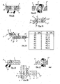
- the present invention relates to the production of conditioned air distribution ducts (1) with a substantially parallelepipedal section, such as that illustrated in FIGS. Figures 1 and 2 with at least one insulating panel (2) comprising at least one insulating layer (3) of mineral wool and preferably of glass wool, said duct (1) having a longitudinal principal axis P.
- insulation duct (1) is intended to convey a conditioning air flow F, the upstream duct being connected to at least one conditioned air source (not shown) and the duct downstream being connected at least one conditioned air distribution mouth (also not shown).
- the air flow F is oriented substantially along the main axis P.
- the minimum requirements for the manufacture and assembly of fiberglass core tubular conduit systems for the forced circulation of air at negative or positive pressures up to 500 Pa and maximum speeds of 10 m / s are defined in a standard.
- the ducts CLIMAVER PLUS and SISTEMA CLIMAVER METAL of the company SAINT GOBAIN ISOVER are suitable for the implementation of the present invention and the respect of the standard because they admit pressures up to 800 Pa and maximum speeds of 18 m / s .
- the duct (1) which is intended to be arranged in a metal duct (not shown) to form a conditioned air transport duct, will be described in more detail below.
- the present disclosure relates more particularly to a method for producing a duct figure, in order to make it possible to achieve at least one change of direction C according to an angle ⁇ , or its complementary angle ⁇ , modifying the main longitudinal axis P , in a primary downstream axis P ', or even in a secondary downstream axis P ", that is to say involving a change of direction simple or with separation of air flow.
- said angle ⁇ is substantially between 30 ° and 60 ° and preferably substantially equal to 45 °.
- the figure 3 illustrates the pressure drop measurements (in Pa) performed on four types of right angle elbows (T1 to T4), of square section 30x30 cm for T1 and T2 and rectangular section 39x32 cm for T3 and T4 depending on the speed air flow (in m / s), T1 and T3 being made according to the prior method and T2 and T4 being manufactured according to the method of this presentation.
- the method of the present invention makes it possible to eliminate the irregularities formed on the inner surface of the duct when a figure is made using the prior method and thus makes it possible to reduce the pressure drops across the duct otherwise generated by these irregularities.
- said change of direction C is made by cutting in a flat panel (2), as illustrated. figure 4 , of each of the faces of said duct (1).
- the faces of the duct which are parallel to the plane comprising said change of direction C each have more than four sides in this plane and preferably six sides for a simple change of direction or eight sides for a double directional change allowing in the end to make a change of direction at right angles. In this way, the sealing of the insulation is even better ensured at the level of the change of direction.
- the change of direction C is made by complete section, that is to say, complete cutting, of an upstream duct (1) into a downstream primary section (1 ') and possibly a downstream secondary section ( 1 ") if the change of direction is double, as well as, possibly, rotation around its axis of the primary section (1 '), see secondary section (1").
- the conduit (1-1'-1 ") is made from a panel (2) such as that illustrated on the figure 5 .
- the first variant of the process produces about 1.5 m 2 of falls to make two 90 ° elbows of 30x35 cm (approximately), illustrated in gray on the figure 4 , while the second variant produces no drop for the manufacture of the same two figures.
- FIGS. 1 and 2 schematically represent this second variant of implementation of the method from a straight section to obtain a change of direction at an angle ⁇ .
- a tubular duct (1) of rectangular section, on four sides of which is carried out, in a traditional way and by appropriate measures, four straight marks (20, 20 ', 20 ", 20'” ) on the four sides of the duct, which, in the case of lines or marks (20, 20 ") form an angle ⁇ with respect to a transverse line of the relevant face at the corner of the duct, and which, in the case of lines (20 ', 20 ") are parallel to said transverse line of the relevant face.
- conduit (1-1 ') bent at an angle ⁇ illustrated on the figure 2 it suffices to turn the primary section (1 ') by 180 ° and to position the rear edges of the downstream primary section (1') against the front edges of the upstream tubular duct (1).
- the conduit (1-1 ') then forms an obtuse elbow, in other words at an angle ⁇ greater than 90 °, to cause a change of direction of the air flow F.
- the figure 6 illustrates a panel (2) for the realization of the tubular duct (1) according to the first or the second variant of implementation of the method.
- This panel (2) comprises at least one insulating layer (3) of mineral wool and preferably glass wool and has a substantially parallelepipedal shape and flat. It also comprises an outer layer (4) which will be outside the tubular insulation duct (1) when it is formed, and optionally an inner layer (4 ') which will be inside the tubular duct ( 1) when it is formed.
- the outer layer (4) is intended to be substantially brought into contact with the metal wall of the conditioned inventive step transport conduit.
- the outer layer (4) further has a plurality of transverse rectilinear marks (6), oriented perpendicular to said transverse edges (9) and a plurality of longitudinal rectilinear marks (7) oriented in the direction of the longitudinal edges (8).
- the straight marks (5, 6, 7) thus make it possible to calibrate the plate (2) and, as a result, the tubular body (1), so as to facilitate the making of markings prior to cutting and cutting.
- the marks (5) have only been illustrated on one side of the duct (1) on the figure 2 to facilitate reading, but it is obvious that they are present on all sides of the conduit (1).
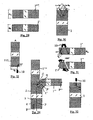
- FIGS 7, 8 and 9 illustrate an embodiment of a duct (1) from a single plate (2) folded along four longitudinal edges at right angles, according to the second variant of implementation of the method.
- the four pieces of the panel intended to form the faces of the duct each have a right longitudinal edge and an opposite longitudinal edge profiled in a stair step, in other words provided with a rabbet depth equal to the edge of the room it will receive when bending at 90 ° and thickness equal to half the thickness thereof.
- One of the parts further comprises an extension of the outer layer which will be stapled over the other part, as can be seen on the figure 9 .
- the sealing is done with a strip of fabric impregnated with plaster and glue or with an adhesive tape of aluminum.
- the sealing of the ducts is particularly tight, air leakage to the outside of the duct being negligible provided that it was manufactured and assembled correctly.
- the transverse connection of elements to form the ductwork is done by placing the surfaces of two sections of duct in the same plane, stapling the flap of one of the sections on the other (without flap) and sealing the connection using an adhesive tape.
- the transverse edges (9) of the elements to be connected are profiled so as to form a so-called "male” section and another so-called “female". On these transverse edges, the density of the glass wool is much greater, which increases the rigidity of the connection and improves the assembly.
- the cutting panels (2) can be achieved using a circular saw connected to a suction system.
- the circular saw shall be equipped with a device for tilting the angle of cut to allow for perpendicular cuts, cuts at 22.5 ° from the vertical, and cuts at 45 ° or more. other angles.
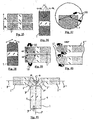
- the cutting of the panels (2) is operated using a particular cutting instrument (10) first illustrated at the figure 10 for the implementation of the second variant.
- This instrument (10) shown in detail Figures 11 to 15 , has a guide surface (12) for sliding on the surface of the panel (2), a handle (14) and two blades (15, 16) located in the same plane and each having a cutting edge (17, 18). .
- These cutting edges (17, 18) are oriented in this plane at inclinations contrary to the guide surface (12).
- the first cutting edge (17), that of the first blade (15) is oriented rearward with respect to the cutting direction and has a height less than the second cutting edge (18), that of the second blade (16). ), which is oriented forward; however, the two blades (15, 16) do not touch each other.
- the first cutting edge (17) has a height less than the total thickness of the panel (2) and the second cutting edge (18) has a height greater than the total thickness of the panel (2).
- the instrument (10) also makes it possible to cut a panel (12), even when the latter is already arranged to form a duct, as can be seen on the figure 13 . Due to the arrangement of the blades (15, 16) and their respective cutting edges (17, 18), it is possible to start cutting a conduit at an angle without causing smudging or delamination.
- the cutting instrument (10) has straight blades (15, 16), that is, oriented perpendicularly to the guide surface (12). This version allows to make straight cuts, like the cuts (20 and 20 ") on the Figures 1 and 2 .
- the cutting instrument (10) has slats (15, 16) inclined, that is to say oriented at an angle ⁇ with respect to the guide surface (12).
- This version makes it possible to make inclined cuts, like the cuts (20 'and 20 "') on the Figures 1 and 2 .
- ⁇ ⁇ .
- the blades (15, 16) are provided with a system for adjusting their inclination with respect to the guide surface (12), or that the blades (15, 16) are removable and cooperate with a rail formed in the guide surface (12), a plurality of rail types imposing different blade inclinations.
- the cutting line is marked on the outer surface (4) of the duct (1) with the help of the marks (5), as illustrated by FIG. figure 16 and is cut with a tangential circular saw or preferably using the instrument (10), following the imaginary plane passing through the duct perpendicular to the main axis P and passing through this section line.
- the slices inclined at ⁇ ° are preferably made first, before those perpendicular to the surface (4) of the conduit.
- the duct is rotated 180 ° on itself, then is positioned so that axis P 'crosses the axis P of the upstream duct, as can be seen on the figure 18 .
- a bead of glue is applied along the edges to be connected, and this near the inner edge duct.
- the connection area is then sealed, outside and on the perimeter, with an aluminum adhesive tape.
- the ribbon will maintain the shape and rigidity of the fitting, both inside and out.
- the outer surface (4) of the panel comprises a template formed of marks (5) facilitating the drawing of lines that will serve as cutting lines.
- the table of the figure 21 exposes the gaps D 1 between the main duct (1) and the secondary section (1 ") as a function of the minimum length A 1 of the primary section (1 ').
- the inflection is a deviation of the direction of the duct sometimes necessary if one wants to avoid the obstacles present on the right trajectory of the duct.
- the duct section is kept constant throughout its course.
- the method of realizing an inflection is very close to the method of producing a 90 ° elbow.
- the outer surface (4) of the panel comprises a template formed of marks (5) facilitating the drawing of lines that will serve as cutting lines.
- the table of the figure 25 exposes the spacings D 2 between the main duct (1) and the secondary section (1 ") as a function of the minimum length A 2 of the primary section (1 ').
- the outer surface (4) of the panel comprises a template formed of marks (5) facilitating the drawing of lines that will serve as cutting lines.
- the first section constitutes the main section (1), illustrated figure 30
- the second section constitutes the primary section (1 '), illustrated figure 29 , of width B K
- the third section constitutes the tertiary section (1"'), also illustrated figure 29 , of width A K.
- the connection of the continuation of the main section in tertiary section and the branch goes through this line.
- the reduced width at K of the tertiary section (1 "') at the intersection which is reported on the tertiary section (1"') is measured on one side, as shown in FIG. figure 33 and a line inclined 22.5 ° with respect to an imaginary perpendicular section is drawn on the outer surface of the other side, thereby obtaining the measurement of the reduced width b K of the primary section (1 ') which is refer to the primary section (1 ') as shown in figure 31 along a line inclined at 22.5 ° with respect to an imaginary perpendicular section.
- a second section is made at an angle of 22.5 ° with respect to an imaginary perpendicular section to form the secondary section (1 "), the primary section must then be turned 180 °, as for a right angle bend (see point b).
- the measured value d K of this segment must be reported on the main pipe (1), illustrated figure 32 , then the width b K must be reported along a line inclined at 22.5 ° with respect to a transverse of the main duct (1).
- the four sections (1, 1 ', 1 ", 1"') are connected in such a way that the respective axes (P, P ', P ") of the sections (1, 1', 1" ) cut in pairs at a 45 ° angle and the axes of the main (1) and tertiary (1 "') sections are parallel, as shown figure 34 .
- the angle ⁇ between the uppermost axis P and the downstream axis P "of the branch is 90 °.
- Each branch (left, right) is thus formed of a primary section (1 ') and a secondary section (1 "), the secondary sections (1") left and right being respectively derived from the primary sections (1') left and right.
- the two elbows at 90 ° may have different downstream sections, the sum of which is greater than the section of the main duct, their height must however be identical to that of the main section.
- the connection of the two branches goes through this line. From this line, two lines inclined by 22.5 ° are drawn on each side, to obtain the measurements a L and b L which are reported on the branches, as shown in the diagram. figure 39 .
Landscapes
- Engineering & Computer Science (AREA)
- General Engineering & Computer Science (AREA)
- Mechanical Engineering (AREA)
- Chemical & Material Sciences (AREA)
- Combustion & Propulsion (AREA)
- Manufacturing & Machinery (AREA)
- Duct Arrangements (AREA)
- Laminated Bodies (AREA)
- Thermal Insulation (AREA)
- Building Environments (AREA)
Claims (3)
- Isolierplatte (2) für eine Leitung zum Verteilen klimatisierter Luft (1), wobei die Isolierplatte (2) einen isolierenden Kern (3) auf der Basis von Mineralwolle, vorzugsweise Glaswolle, aufweist und eine Außenschicht (4) beispielweise auf der Basis eines dünnen Aluminiumfilms umfasst, dadurchgekennzeichnet, dass sie auf einer Außenseite der Außenschicht eine Vielzahl von geradlinigen und gegenüber einer Längsrichtung der Platte schräg verlaufenden Markierungen (5) aufweist, wobei die Markierungen zwei Gruppen mit entgegengesetzten Neigungen bilden, die unter einem Winkel γ gleich 67,5° gegenüber der Längsrichtung ausgerichtet sind, und dadurch, dass die Außenseite außerdem eine Vielzahl von geradlinigen Längsmarkierungen (7) aufweist, die parallel zur Längsrichtung ausgerichtet sind.
- Isolierplatte nach Anspruch 1, dadurch gekennzeichnet, dass die Außenseite ferner eine Vielzahl von geradlinigen querverlaufenden Markierungen (6) aufweist, die senkrecht zur Längsrichtung ausgerichtet sind.
- Verteilungleitung (1) mit einem im wesentlichen quaderförmigen Querschnitt, die aus wenigstens einer Isolierplatte (2) nach einem der vorgehenden Ansprüche gebildet ist.
Priority Applications (1)
| Application Number | Priority Date | Filing Date | Title |
|---|---|---|---|
| SI200331603T SI1532391T2 (sl) | 2002-06-24 | 2003-06-18 | Izolirna plošča za dovodni kanal |
Applications Claiming Priority (5)
| Application Number | Priority Date | Filing Date | Title |
|---|---|---|---|
| ES201600001U | 2002-06-24 | ||
| ES200201600U ES1052377Y (es) | 2002-06-24 | 2002-06-24 | Herramienta de corte para conductos de aire acondicionado. |
| ES201600000U | 2002-06-24 | ||
| ES200201601U ES1052378Y (es) | 2002-06-24 | 2002-06-24 | Panel para conductos de distribucion de aire acondicionado. |
| PCT/FR2003/001854 WO2004001277A1 (fr) | 2002-06-24 | 2003-06-18 | Panneau d'isolation pour conduit de distribution |
Publications (3)
| Publication Number | Publication Date |
|---|---|
| EP1532391A1 EP1532391A1 (de) | 2005-05-25 |
| EP1532391B1 EP1532391B1 (de) | 2009-03-18 |
| EP1532391B2 true EP1532391B2 (de) | 2019-03-06 |
Family
ID=30001915
Family Applications (1)
| Application Number | Title | Priority Date | Filing Date |
|---|---|---|---|
| EP03760735.5A Expired - Lifetime EP1532391B2 (de) | 2002-06-24 | 2003-06-18 | ISOLIERPLATTE FüR ZUFUHRKANAL |
Country Status (15)
| Country | Link |
|---|---|
| US (1) | US7798176B2 (de) |
| EP (1) | EP1532391B2 (de) |
| CN (1) | CN100516622C (de) |
| AR (1) | AR040470A1 (de) |
| AT (1) | ATE426127T2 (de) |
| AU (1) | AU2003260599A1 (de) |
| BR (1) | BRPI0312016B1 (de) |
| CA (1) | CA2490055C (de) |
| DE (1) | DE60326733D1 (de) |
| DK (1) | DK1532391T4 (de) |
| ES (1) | ES2324530T5 (de) |
| PT (1) | PT1532391E (de) |
| RU (1) | RU2305815C2 (de) |
| SI (1) | SI1532391T2 (de) |
| WO (1) | WO2004001277A1 (de) |
Families Citing this family (15)
| Publication number | Priority date | Publication date | Assignee | Title |
|---|---|---|---|---|
| EP2045505A1 (de) * | 2007-10-02 | 2009-04-08 | Logstor A/S | Vorisolierte flexible Röhrenanordnung |
| FR2986255A1 (fr) * | 2012-02-01 | 2013-08-02 | Egis Conseil Batiments | Conduit prefabrique etanche etcoupe feu et procede de realisation |
| US8667995B1 (en) * | 2012-05-23 | 2014-03-11 | Carl Fanelli | Insulated ducts and insulated ductworks |
| ES1077290Y (es) * | 2012-06-06 | 2012-09-21 | Saint Gobain Cristaleria S L | Panel para conductos de aire |
| US9528261B2 (en) | 2013-01-09 | 2016-12-27 | Vita Nonwovens, Llc | Synthetic fiber insulation with facing |
| ITMI20131540A1 (it) * | 2013-09-19 | 2015-03-20 | Carpenteria Leggera Aerotecnica C L A S R L | Dispositivo di insonorizzazione, particolarmente per canali di ventilazione. |
| FR3033021B1 (fr) * | 2015-02-19 | 2017-11-24 | Saint Gobain Isover Iberica S L | Enveloppe revetue de reperes |
| US10578335B2 (en) * | 2018-04-04 | 2020-03-03 | Daniel Frank Nolin | Insulated air transfer duct |
| ES2780998B2 (es) * | 2019-02-25 | 2022-06-24 | Saint Gobain Isover Iberica S L | Dispositivo de corte para el cortado de planchas de lana mineral o similar |
| ES2911848R1 (es) * | 2019-02-25 | 2022-07-19 | Saint Gobain Isover Iberica S L | Herramienta de machihembrados en conductos de lana mineral o similar |
| FR3114045B1 (fr) | 2020-09-14 | 2022-12-23 | Saint Gobain Isover Iberica S L | Panneau pour conduits de climatisation |
| GB202018461D0 (en) * | 2020-11-24 | 2021-01-06 | Knauf Insulation Doo Skofja Loka | Insulating panel |
| EP4393839A1 (de) | 2022-12-27 | 2024-07-03 | URSA Insulation S.A. | Dämmungsverpackungsmaterial und dämmungsplattenverpackungen |
| EP4578795A1 (de) | 2023-12-27 | 2025-07-02 | URSA Insulation S.A. | Dämmplattenverpackung mit verpackungseinsatz |
| JP7807121B1 (ja) * | 2025-02-23 | 2026-01-27 | 株式会社山久トータルプラン | 断熱部材 |
Citations (12)
| Publication number | Priority date | Publication date | Assignee | Title |
|---|---|---|---|---|
| US3092529A (en) † | 1955-07-01 | 1963-06-04 | Owens Corning Fiberglass Corp | Duct or conduit blank |
| DE1190391B (de) † | 1958-02-20 | 1965-04-01 | Gewerk Eisenhuette Westfalia | Foerderer mit ruhender Rinne, insbesondere fuer Kohle |
| US4064627A (en) † | 1976-12-15 | 1977-12-27 | Vincent Zanfini | Carpet cutter |
| US4064626A (en) † | 1976-09-09 | 1977-12-27 | Cbs Inc. | Cutter for sheet material |
| FR2409755A1 (fr) † | 1977-11-25 | 1979-06-22 | Buzas Andre | Medicaments a base de nouvelles indolo (2,3-a) quinolizidines |
| US4179808A (en) † | 1978-05-10 | 1979-12-25 | Johns-Manville Corporation | Cutting guide tool for fabrication of air duct transitions and method of its use |
| US4183379A (en) † | 1975-12-03 | 1980-01-15 | Mutz Corp. | Duct board assembly |
| GB2189273A (en) † | 1986-04-16 | 1987-10-21 | Saint Gobain Isover | A method of installing between supports such as rafters a mineral fibre material provided in roll form, a mineral fibre strip suitable for carrying out the method and a method of producing the said mineral fibre strip |
| US5040297A (en) † | 1989-12-01 | 1991-08-20 | Malco Products, Inc. | Fiberglass panel cutter with adjustable square and duct knife |
| US5750225A (en) † | 1995-05-26 | 1998-05-12 | Compac Corporation | Laminated vapor barrier |
| US5783268A (en) † | 1993-08-11 | 1998-07-21 | Knauf Fiber Glass Gmbh | High air velocity duct board having minimal turbulence |
| US20010003993A1 (en) † | 1999-12-13 | 2001-06-21 | Faverio Louis P. | Thermal insulating panels |
Family Cites Families (7)
| Publication number | Priority date | Publication date | Assignee | Title |
|---|---|---|---|---|
| FR2409855A1 (fr) | 1977-11-24 | 1979-06-22 | Chollet Jacques | Element prefabrique destine notamment a la construction de gaines |
| US5172731A (en) * | 1989-02-13 | 1992-12-22 | Soltech, Inc. | Thermal insulation blanket |
| RU2042087C1 (ru) * | 1991-04-08 | 1995-08-20 | Полтавский инженерно-строительный институт | Система вентиляции здания |
| FR2740804B1 (fr) | 1995-11-03 | 1997-12-05 | Saint Gobain Isover | Gaine de ventilation et panneau isolant utilise pour son revetement interne |
| ES2175050T3 (es) * | 1995-11-03 | 2002-11-16 | Saint Gobain Isover | Conducto de ventilacion y panel aislante utilizado para su revestimiento. |
| CA2226595C (en) * | 1998-01-12 | 2003-12-02 | Emco Limited | Composite vapour barrier panel |
| RU44040U1 (ru) * | 2004-04-20 | 2005-02-27 | Григорьев Валерий Васильевич | Технологический блок чистых помещений |
-
2003
- 2003-06-18 DE DE60326733T patent/DE60326733D1/de not_active Expired - Lifetime
- 2003-06-18 US US10/517,616 patent/US7798176B2/en active Active
- 2003-06-18 AU AU2003260599A patent/AU2003260599A1/en not_active Abandoned
- 2003-06-18 ES ES03760735T patent/ES2324530T5/es not_active Expired - Lifetime
- 2003-06-18 PT PT03760735T patent/PT1532391E/pt unknown
- 2003-06-18 WO PCT/FR2003/001854 patent/WO2004001277A1/fr not_active Ceased
- 2003-06-18 AT AT03760735T patent/ATE426127T2/de active
- 2003-06-18 CN CNB038201062A patent/CN100516622C/zh not_active Expired - Lifetime
- 2003-06-18 RU RU2005101418/06A patent/RU2305815C2/ru active
- 2003-06-18 DK DK03760735.5T patent/DK1532391T4/da active
- 2003-06-18 BR BRPI0312016A patent/BRPI0312016B1/pt active IP Right Grant
- 2003-06-18 CA CA2490055A patent/CA2490055C/fr not_active Expired - Lifetime
- 2003-06-18 SI SI200331603T patent/SI1532391T2/sl unknown
- 2003-06-18 EP EP03760735.5A patent/EP1532391B2/de not_active Expired - Lifetime
- 2003-06-24 AR AR20030102245A patent/AR040470A1/es active IP Right Grant
Patent Citations (12)
| Publication number | Priority date | Publication date | Assignee | Title |
|---|---|---|---|---|
| US3092529A (en) † | 1955-07-01 | 1963-06-04 | Owens Corning Fiberglass Corp | Duct or conduit blank |
| DE1190391B (de) † | 1958-02-20 | 1965-04-01 | Gewerk Eisenhuette Westfalia | Foerderer mit ruhender Rinne, insbesondere fuer Kohle |
| US4183379A (en) † | 1975-12-03 | 1980-01-15 | Mutz Corp. | Duct board assembly |
| US4064626A (en) † | 1976-09-09 | 1977-12-27 | Cbs Inc. | Cutter for sheet material |
| US4064627A (en) † | 1976-12-15 | 1977-12-27 | Vincent Zanfini | Carpet cutter |
| FR2409755A1 (fr) † | 1977-11-25 | 1979-06-22 | Buzas Andre | Medicaments a base de nouvelles indolo (2,3-a) quinolizidines |
| US4179808A (en) † | 1978-05-10 | 1979-12-25 | Johns-Manville Corporation | Cutting guide tool for fabrication of air duct transitions and method of its use |
| GB2189273A (en) † | 1986-04-16 | 1987-10-21 | Saint Gobain Isover | A method of installing between supports such as rafters a mineral fibre material provided in roll form, a mineral fibre strip suitable for carrying out the method and a method of producing the said mineral fibre strip |
| US5040297A (en) † | 1989-12-01 | 1991-08-20 | Malco Products, Inc. | Fiberglass panel cutter with adjustable square and duct knife |
| US5783268A (en) † | 1993-08-11 | 1998-07-21 | Knauf Fiber Glass Gmbh | High air velocity duct board having minimal turbulence |
| US5750225A (en) † | 1995-05-26 | 1998-05-12 | Compac Corporation | Laminated vapor barrier |
| US20010003993A1 (en) † | 1999-12-13 | 2001-06-21 | Faverio Louis P. | Thermal insulating panels |
Also Published As
| Publication number | Publication date |
|---|---|
| US7798176B2 (en) | 2010-09-21 |
| PT1532391E (pt) | 2009-06-25 |
| CN100516622C (zh) | 2009-07-22 |
| SI1532391T1 (sl) | 2009-08-31 |
| WO2004001277A1 (fr) | 2003-12-31 |
| ES2324530T5 (es) | 2019-10-25 |
| US20060096652A1 (en) | 2006-05-11 |
| AR040470A1 (es) | 2005-04-06 |
| AU2003260599A1 (en) | 2004-01-06 |
| EP1532391B1 (de) | 2009-03-18 |
| DK1532391T3 (da) | 2009-06-29 |
| CN1678863A (zh) | 2005-10-05 |
| DE60326733D1 (de) | 2009-04-30 |
| SI1532391T2 (sl) | 2019-06-28 |
| RU2005101418A (ru) | 2005-09-20 |
| ES2324530T3 (es) | 2009-08-10 |
| EP1532391A1 (de) | 2005-05-25 |
| BR0312016A (pt) | 2005-03-22 |
| DK1532391T4 (da) | 2019-06-24 |
| CA2490055C (fr) | 2011-10-18 |
| BRPI0312016B1 (pt) | 2015-10-20 |
| CA2490055A1 (fr) | 2003-12-31 |
| RU2305815C2 (ru) | 2007-09-10 |
| ATE426127T2 (de) | 2009-04-15 |
Similar Documents
| Publication | Publication Date | Title |
|---|---|---|
| EP1532391B2 (de) | ISOLIERPLATTE FüR ZUFUHRKANAL | |
| FR2976820A1 (fr) | Element filtrant avec des puits de guidage | |
| CA2933123A1 (fr) | Piece de turbomachine a surface non-axisymetrique definissant une pluralite d'ailettes | |
| WO2009103891A2 (fr) | Dispositif de soufflage de gaz sur une face d'un materiau en bande en defilement | |
| CA2703836A1 (en) | Non-metallic raceway for wiring and fiber optic cable and method of forming raceway | |
| EP1734203A1 (de) | Eckstück für ein Fussbodenbelag im Bereich einer Innenecke zwischen Boden und angrenzenden Wänden, sowie entsprechendes Verlegeverfahren | |
| FR2501847A1 (fr) | Infrastructure a plaques pour echangeur de chaleur pose en nappe | |
| EP2795229A1 (de) | Platte für wärmeaustauscher | |
| EP3645184A1 (de) | Rohr für einen wärmetauscher mit störvorrichtung | |
| EP3234473B1 (de) | Seitlicher belüfter und belüftungskanal mit zumindest einem solchen belüfter | |
| KR100972446B1 (ko) | 공기 조화 공급 도관용 단열성 패널, 공급 도관, 공급 도관을 제조하는 방법, 및 단열성 패널을 절단하는 절단 기구 | |
| FR2982181A1 (fr) | Procede de cintrage de profiles notamment tubulaires | |
| EP4283806A2 (de) | Verbindungselement für kabelrinnenabschnitte aus drahtgitter | |
| FR3144830A1 (fr) | « Système de pose de lames de revêtement de sol en motif bâton rompu » | |
| EP4269900A1 (de) | Verteilerleitung zur verteilung von klimatisierter luft | |
| WO2006035149A1 (fr) | Intercalaire d'échange de chaleur pour un dispositif d'échange de chaleur | |
| WO2013113700A1 (fr) | Tube d'échangeur thermique, échangeur thermique et procédé d'obtention correspondant | |
| FR3010109A1 (fr) | Boite de reservation et procedes de montage d'une telle boite | |
| FR3079016A1 (fr) | Raccord aeraulique | |
| FR3164014A1 (fr) | Dispositif générateur de turbulence atmosphérique basse altitude et soufflerie associée | |
| US20120297850A1 (en) | Method of preparing a metallic tape for use on a joint | |
| FR3138460A1 (fr) | Boite de reservation pourvue d’une partie aimantee | |
| EP3748097A1 (de) | Metallrahmen für vorgefertigte trockenbau-platten | |
| WO2022229811A1 (fr) | Dispositif de raccordement coude multi-angles | |
| FR3111683A1 (fr) | Dispositif amovible d’orientation de flux d’air secondaire destiné à équiper un conduit principal d’air, ensemble de conduite et de distribution d’air comprenant au moins un tel dispositif, conduit d’air associé et procédé d’assemblage d’un tel conduit équipé |
Legal Events
| Date | Code | Title | Description |
|---|---|---|---|
| PUAI | Public reference made under article 153(3) epc to a published international application that has entered the european phase |
Free format text: ORIGINAL CODE: 0009012 |
|
| 17P | Request for examination filed |
Effective date: 20041209 |
|
| AK | Designated contracting states |
Kind code of ref document: A1 Designated state(s): AT BE BG CH CY CZ DE DK EE ES FI FR GB GR HU IE IT LI LU MC NL PT RO SE SI SK TR |
|
| AX | Request for extension of the european patent |
Extension state: AL LT LV MK |
|
| DAX | Request for extension of the european patent (deleted) | ||
| 17Q | First examination report despatched |
Effective date: 20080416 |
|
| GRAP | Despatch of communication of intention to grant a patent |
Free format text: ORIGINAL CODE: EPIDOSNIGR1 |
|
| GRAS | Grant fee paid |
Free format text: ORIGINAL CODE: EPIDOSNIGR3 |
|
| GRAA | (expected) grant |
Free format text: ORIGINAL CODE: 0009210 |
|
| AK | Designated contracting states |
Kind code of ref document: B1 Designated state(s): AT BE BG CH CY CZ DE DK EE ES FI FR GB GR HU IE IT LI LU MC NL PT RO SE SI SK TR |
|
| REG | Reference to a national code |
Ref country code: GB Ref legal event code: FG4D Free format text: NOT ENGLISH |
|
| REG | Reference to a national code |
Ref country code: CH Ref legal event code: EP |
|
| REG | Reference to a national code |
Ref country code: IE Ref legal event code: FG4D Free format text: LANGUAGE OF EP DOCUMENT: FRENCH |
|
| REF | Corresponds to: |
Ref document number: 60326733 Country of ref document: DE Date of ref document: 20090430 Kind code of ref document: P |
|
| REG | Reference to a national code |
Ref country code: RO Ref legal event code: EPE |
|
| REG | Reference to a national code |
Ref country code: PT Ref legal event code: SC4A Free format text: AVAILABILITY OF NATIONAL TRANSLATION Effective date: 20090618 |
|
| REG | Reference to a national code |
Ref country code: DK Ref legal event code: T3 |
|
| REG | Reference to a national code |
Ref country code: SE Ref legal event code: TRGR |
|
| REG | Reference to a national code |
Ref country code: GR Ref legal event code: EP Ref document number: 20090401533 Country of ref document: GR |
|
| REG | Reference to a national code |
Ref country code: ES Ref legal event code: FG2A Ref document number: 2324530 Country of ref document: ES Kind code of ref document: T3 |
|
| PG25 | Lapsed in a contracting state [announced via postgrant information from national office to epo] |
Ref country code: EE Free format text: LAPSE BECAUSE OF FAILURE TO SUBMIT A TRANSLATION OF THE DESCRIPTION OR TO PAY THE FEE WITHIN THE PRESCRIBED TIME-LIMIT Effective date: 20090318 |
|
| PG25 | Lapsed in a contracting state [announced via postgrant information from national office to epo] |
Ref country code: SK Free format text: LAPSE BECAUSE OF FAILURE TO SUBMIT A TRANSLATION OF THE DESCRIPTION OR TO PAY THE FEE WITHIN THE PRESCRIBED TIME-LIMIT Effective date: 20090318 |
|
| PLBI | Opposition filed |
Free format text: ORIGINAL CODE: 0009260 |
|
| PLAX | Notice of opposition and request to file observation + time limit sent |
Free format text: ORIGINAL CODE: EPIDOSNOBS2 |
|
| 26 | Opposition filed |
Opponent name: KNAUF INSULATION TECHNOLOGY SPRL Effective date: 20091217 |
|
| PG25 | Lapsed in a contracting state [announced via postgrant information from national office to epo] |
Ref country code: MC Free format text: LAPSE BECAUSE OF NON-PAYMENT OF DUE FEES Effective date: 20090630 |
|
| REG | Reference to a national code |
Ref country code: CH Ref legal event code: PL |
|
| NLR1 | Nl: opposition has been filed with the epo |
Opponent name: KNAUF INSULATION TECHNOLOGY SPRL |
|
| PG25 | Lapsed in a contracting state [announced via postgrant information from national office to epo] |
Ref country code: CH Free format text: LAPSE BECAUSE OF NON-PAYMENT OF DUE FEES Effective date: 20090630 Ref country code: LI Free format text: LAPSE BECAUSE OF NON-PAYMENT OF DUE FEES Effective date: 20090630 |
|
| PLAF | Information modified related to communication of a notice of opposition and request to file observations + time limit |
Free format text: ORIGINAL CODE: EPIDOSCOBS2 |
|
| REG | Reference to a national code |
Ref country code: HU Ref legal event code: AG4A Ref document number: E007282 Country of ref document: HU |
|
| PLBB | Reply of patent proprietor to notice(s) of opposition received |
Free format text: ORIGINAL CODE: EPIDOSNOBS3 |
|
| PG25 | Lapsed in a contracting state [announced via postgrant information from national office to epo] |
Ref country code: GR Free format text: LAPSE BECAUSE OF NON-PAYMENT OF DUE FEES Effective date: 20100107 |
|
| PG25 | Lapsed in a contracting state [announced via postgrant information from national office to epo] |
Ref country code: LU Free format text: LAPSE BECAUSE OF NON-PAYMENT OF DUE FEES Effective date: 20090618 |
|
| PG25 | Lapsed in a contracting state [announced via postgrant information from national office to epo] |
Ref country code: CY Free format text: LAPSE BECAUSE OF FAILURE TO SUBMIT A TRANSLATION OF THE DESCRIPTION OR TO PAY THE FEE WITHIN THE PRESCRIBED TIME-LIMIT Effective date: 20090318 |
|
| PLAY | Examination report in opposition despatched + time limit |
Free format text: ORIGINAL CODE: EPIDOSNORE2 |
|
| PLBC | Reply to examination report in opposition received |
Free format text: ORIGINAL CODE: EPIDOSNORE3 |
|
| APBM | Appeal reference recorded |
Free format text: ORIGINAL CODE: EPIDOSNREFNO |
|
| APBP | Date of receipt of notice of appeal recorded |
Free format text: ORIGINAL CODE: EPIDOSNNOA2O |
|
| APAH | Appeal reference modified |
Free format text: ORIGINAL CODE: EPIDOSCREFNO |
|
| APBM | Appeal reference recorded |
Free format text: ORIGINAL CODE: EPIDOSNREFNO |
|
| APBP | Date of receipt of notice of appeal recorded |
Free format text: ORIGINAL CODE: EPIDOSNNOA2O |
|
| APBQ | Date of receipt of statement of grounds of appeal recorded |
Free format text: ORIGINAL CODE: EPIDOSNNOA3O |
|
| REG | Reference to a national code |
Ref country code: FR Ref legal event code: PLFP Year of fee payment: 14 |
|
| REG | Reference to a national code |
Ref country code: FR Ref legal event code: PLFP Year of fee payment: 15 |
|
| PLAB | Opposition data, opponent's data or that of the opponent's representative modified |
Free format text: ORIGINAL CODE: 0009299OPPO |
|
| R26 | Opposition filed (corrected) |
Opponent name: KNAUF INSULATION TECHNOLOGY SPRL Effective date: 20091217 |
|
| APBU | Appeal procedure closed |
Free format text: ORIGINAL CODE: EPIDOSNNOA9O |
|
| REG | Reference to a national code |
Ref country code: FR Ref legal event code: PLFP Year of fee payment: 16 |
|
| PUAH | Patent maintained in amended form |
Free format text: ORIGINAL CODE: 0009272 |
|
| STAA | Information on the status of an ep patent application or granted ep patent |
Free format text: STATUS: PATENT MAINTAINED AS AMENDED |
|
| 27A | Patent maintained in amended form |
Effective date: 20190306 |
|
| AK | Designated contracting states |
Kind code of ref document: B2 Designated state(s): AT BE BG CH CY CZ DE DK EE ES FI FR GB GR HU IE IT LI LU MC NL PT RO SE SI SK TR |
|
| REG | Reference to a national code |
Ref country code: DE Ref legal event code: R102 Ref document number: 60326733 Country of ref document: DE |
|
| REG | Reference to a national code |
Ref country code: SE Ref legal event code: RPEO |
|
| REG | Reference to a national code |
Ref country code: NL Ref legal event code: FP |
|
| REG | Reference to a national code |
Ref country code: DK Ref legal event code: T4 Effective date: 20190621 |
|
| REG | Reference to a national code |
Ref country code: DE Ref legal event code: R082 Ref document number: 60326733 Country of ref document: DE |
|
| PGFP | Annual fee paid to national office [announced via postgrant information from national office to epo] |
Ref country code: BE Payment date: 20190227 Year of fee payment: 17 |
|
| PG25 | Lapsed in a contracting state [announced via postgrant information from national office to epo] |
Ref country code: GR Free format text: LAPSE BECAUSE OF FAILURE TO SUBMIT A TRANSLATION OF THE DESCRIPTION OR TO PAY THE FEE WITHIN THE PRESCRIBED TIME-LIMIT Effective date: 20190607 |
|
| PGFP | Annual fee paid to national office [announced via postgrant information from national office to epo] |
Ref country code: HU Payment date: 20190516 Year of fee payment: 17 Ref country code: BG Payment date: 20190517 Year of fee payment: 17 |
|
| REG | Reference to a national code |
Ref country code: ES Ref legal event code: DC2A Ref document number: 2324530 Country of ref document: ES Kind code of ref document: T5 Effective date: 20191025 |
|
| REG | Reference to a national code |
Ref country code: AT Ref legal event code: MM01 Ref document number: 426127 Country of ref document: AT Kind code of ref document: T Effective date: 20200618 |
|
| REG | Reference to a national code |
Ref country code: BE Ref legal event code: MM Effective date: 20200630 |
|
| PG25 | Lapsed in a contracting state [announced via postgrant information from national office to epo] |
Ref country code: IE Free format text: LAPSE BECAUSE OF NON-PAYMENT OF DUE FEES Effective date: 20200618 Ref country code: HU Free format text: LAPSE BECAUSE OF NON-PAYMENT OF DUE FEES Effective date: 20200619 |
|
| PG25 | Lapsed in a contracting state [announced via postgrant information from national office to epo] |
Ref country code: BG Free format text: LAPSE BECAUSE OF NON-PAYMENT OF DUE FEES Effective date: 20201231 Ref country code: BE Free format text: LAPSE BECAUSE OF NON-PAYMENT OF DUE FEES Effective date: 20200630 Ref country code: AT Free format text: LAPSE BECAUSE OF NON-PAYMENT OF DUE FEES Effective date: 20200618 |
|
| PGFP | Annual fee paid to national office [announced via postgrant information from national office to epo] |
Ref country code: NL Payment date: 20220513 Year of fee payment: 20 |
|
| PGFP | Annual fee paid to national office [announced via postgrant information from national office to epo] |
Ref country code: SE Payment date: 20220510 Year of fee payment: 20 Ref country code: RO Payment date: 20220520 Year of fee payment: 20 Ref country code: PT Payment date: 20220619 Year of fee payment: 20 Ref country code: IT Payment date: 20220510 Year of fee payment: 20 Ref country code: GB Payment date: 20220506 Year of fee payment: 20 Ref country code: DK Payment date: 20220610 Year of fee payment: 20 Ref country code: DE Payment date: 20220505 Year of fee payment: 20 Ref country code: CZ Payment date: 20220526 Year of fee payment: 20 |
|
| PGFP | Annual fee paid to national office [announced via postgrant information from national office to epo] |
Ref country code: TR Payment date: 20220615 Year of fee payment: 20 Ref country code: SI Payment date: 20220518 Year of fee payment: 20 Ref country code: FI Payment date: 20220609 Year of fee payment: 20 |
|
| PGFP | Annual fee paid to national office [announced via postgrant information from national office to epo] |
Ref country code: FR Payment date: 20220630 Year of fee payment: 20 |
|
| PGFP | Annual fee paid to national office [announced via postgrant information from national office to epo] |
Ref country code: ES Payment date: 20220706 Year of fee payment: 20 |
|
| REG | Reference to a national code |
Ref country code: AT Ref legal event code: UEP Ref document number: 426127 Country of ref document: AT Kind code of ref document: T Effective date: 20190306 |
|
| REG | Reference to a national code |
Ref country code: DE Ref legal event code: R071 Ref document number: 60326733 Country of ref document: DE |
|
| REG | Reference to a national code |
Ref country code: DK Ref legal event code: EUP Expiry date: 20230618 |
|
| REG | Reference to a national code |
Ref country code: NL Ref legal event code: MK Effective date: 20230617 |
|
| REG | Reference to a national code |
Ref country code: ES Ref legal event code: FD2A Effective date: 20230626 |
|
| REG | Reference to a national code |
Ref country code: GB Ref legal event code: PE20 Expiry date: 20230617 |
|
| PG25 | Lapsed in a contracting state [announced via postgrant information from national office to epo] |
Ref country code: PT Free format text: LAPSE BECAUSE OF EXPIRATION OF PROTECTION Effective date: 20230628 Ref country code: ES Free format text: LAPSE BECAUSE OF EXPIRATION OF PROTECTION Effective date: 20230619 Ref country code: CZ Free format text: LAPSE BECAUSE OF EXPIRATION OF PROTECTION Effective date: 20230618 |
|
| REG | Reference to a national code |
Ref country code: SE Ref legal event code: EUG |
|
| PG25 | Lapsed in a contracting state [announced via postgrant information from national office to epo] |
Ref country code: SI Free format text: LAPSE BECAUSE OF EXPIRATION OF PROTECTION Effective date: 20230619 |
|
| PG25 | Lapsed in a contracting state [announced via postgrant information from national office to epo] |
Ref country code: GB Free format text: LAPSE BECAUSE OF EXPIRATION OF PROTECTION Effective date: 20230617 |