EP1532391B2 - Insulation panel for supply duct - Google Patents
Insulation panel for supply duct Download PDFInfo
- Publication number
- EP1532391B2 EP1532391B2 EP03760735.5A EP03760735A EP1532391B2 EP 1532391 B2 EP1532391 B2 EP 1532391B2 EP 03760735 A EP03760735 A EP 03760735A EP 1532391 B2 EP1532391 B2 EP 1532391B2
- Authority
- EP
- European Patent Office
- Prior art keywords
- duct
- section
- angle
- panel
- cutting
- Prior art date
- Legal status (The legal status is an assumption and is not a legal conclusion. Google has not performed a legal analysis and makes no representation as to the accuracy of the status listed.)
- Expired - Lifetime
Links
- 238000009413 insulation Methods 0.000 title description 12
- 238000009826 distribution Methods 0.000 claims description 14
- 239000011490 mineral wool Substances 0.000 claims description 7
- 229910052782 aluminium Inorganic materials 0.000 claims description 6
- XAGFODPZIPBFFR-UHFFFAOYSA-N aluminium Chemical compound [Al] XAGFODPZIPBFFR-UHFFFAOYSA-N 0.000 claims description 6
- 238000005520 cutting process Methods 0.000 description 55
- 238000000034 method Methods 0.000 description 35
- 238000004519 manufacturing process Methods 0.000 description 14
- 230000001143 conditioned effect Effects 0.000 description 11
- 238000011144 upstream manufacturing Methods 0.000 description 9
- 238000005259 measurement Methods 0.000 description 8
- 238000007789 sealing Methods 0.000 description 8
- 230000004048 modification Effects 0.000 description 7
- 238000012986 modification Methods 0.000 description 7
- 239000011491 glass wool Substances 0.000 description 6
- 229910052751 metal Inorganic materials 0.000 description 5
- 239000002184 metal Substances 0.000 description 5
- 230000000295 complement effect Effects 0.000 description 4
- 239000002390 adhesive tape Substances 0.000 description 3
- 239000003292 glue Substances 0.000 description 3
- 238000000926 separation method Methods 0.000 description 3
- 230000001154 acute effect Effects 0.000 description 2
- 230000032798 delamination Effects 0.000 description 2
- 238000004378 air conditioning Methods 0.000 description 1
- 239000011324 bead Substances 0.000 description 1
- 238000005452 bending Methods 0.000 description 1
- 230000015572 biosynthetic process Effects 0.000 description 1
- 230000003750 conditioning effect Effects 0.000 description 1
- 238000010276 construction Methods 0.000 description 1
- 238000010586 diagram Methods 0.000 description 1
- 239000000428 dust Substances 0.000 description 1
- 239000004744 fabric Substances 0.000 description 1
- 239000011152 fibreglass Substances 0.000 description 1
- 239000010408 film Substances 0.000 description 1
- 238000009434 installation Methods 0.000 description 1
- 239000011810 insulating material Substances 0.000 description 1
- 238000005304 joining Methods 0.000 description 1
- 238000012423 maintenance Methods 0.000 description 1
- 239000000463 material Substances 0.000 description 1
- 239000011505 plaster Substances 0.000 description 1
- 230000000750 progressive effect Effects 0.000 description 1
- 238000010079 rubber tapping Methods 0.000 description 1
- 239000007787 solid Substances 0.000 description 1
- 239000010409 thin film Substances 0.000 description 1
Images


Classifications
-
- F—MECHANICAL ENGINEERING; LIGHTING; HEATING; WEAPONS; BLASTING
- F24—HEATING; RANGES; VENTILATING
- F24F—AIR-CONDITIONING; AIR-HUMIDIFICATION; VENTILATION; USE OF AIR CURRENTS FOR SCREENING
- F24F13/00—Details common to, or for air-conditioning, air-humidification, ventilation or use of air currents for screening
- F24F13/02—Ducting arrangements
- F24F13/0263—Insulation for air ducts
-
- F—MECHANICAL ENGINEERING; LIGHTING; HEATING; WEAPONS; BLASTING
- F16—ENGINEERING ELEMENTS AND UNITS; GENERAL MEASURES FOR PRODUCING AND MAINTAINING EFFECTIVE FUNCTIONING OF MACHINES OR INSTALLATIONS; THERMAL INSULATION IN GENERAL
- F16L—PIPES; JOINTS OR FITTINGS FOR PIPES; SUPPORTS FOR PIPES, CABLES OR PROTECTIVE TUBING; MEANS FOR THERMAL INSULATION IN GENERAL
- F16L59/00—Thermal insulation in general
- F16L59/04—Arrangements using dry fillers, e.g. using slag wool which is added to the object to be insulated by pouring, spreading, spraying or the like
-
- F—MECHANICAL ENGINEERING; LIGHTING; HEATING; WEAPONS; BLASTING
- F16—ENGINEERING ELEMENTS AND UNITS; GENERAL MEASURES FOR PRODUCING AND MAINTAINING EFFECTIVE FUNCTIONING OF MACHINES OR INSTALLATIONS; THERMAL INSULATION IN GENERAL
- F16L—PIPES; JOINTS OR FITTINGS FOR PIPES; SUPPORTS FOR PIPES, CABLES OR PROTECTIVE TUBING; MEANS FOR THERMAL INSULATION IN GENERAL
- F16L59/00—Thermal insulation in general
- F16L59/14—Arrangements for the insulation of pipes or pipe systems
- F16L59/143—Pre-insulated pipes
-
- F—MECHANICAL ENGINEERING; LIGHTING; HEATING; WEAPONS; BLASTING
- F24—HEATING; RANGES; VENTILATING
- F24F—AIR-CONDITIONING; AIR-HUMIDIFICATION; VENTILATION; USE OF AIR CURRENTS FOR SCREENING
- F24F13/00—Details common to, or for air-conditioning, air-humidification, ventilation or use of air currents for screening
- F24F13/02—Ducting arrangements
- F24F13/0209—Ducting arrangements characterised by their connecting means, e.g. flanges
-
- F—MECHANICAL ENGINEERING; LIGHTING; HEATING; WEAPONS; BLASTING
- F24—HEATING; RANGES; VENTILATING
- F24F—AIR-CONDITIONING; AIR-HUMIDIFICATION; VENTILATION; USE OF AIR CURRENTS FOR SCREENING
- F24F13/00—Details common to, or for air-conditioning, air-humidification, ventilation or use of air currents for screening
- F24F13/02—Ducting arrangements
- F24F13/0245—Manufacturing or assembly of air ducts; Methods therefor
Definitions
- the present invention relates to an insulation panel for conditioned air distribution duct, said insulating panel comprising at least one insulating core based on mineral wool, preferably glass wool, and comprising an outer layer by example based on a thin film of aluminum.
- the document FR 2,740,804 discloses such an insulating panel comprising an insulating core based on mineral wool and an outer layer based on aluminum.
- the present invention relates more particularly to the manufacture in duct buildings for the transport and distribution of conditioned air.
- ducts generally have a metal structure composed of a self-supporting frame and metal plates disposed between the uprights of this frame, as well as inside this duct, an insulation made from insulating panels.
- the manufacture of these conduits for transporting and distributing conditioned air requires changes in the direction of the duct, in order to ensure the distribution of air at different points.
- the prior art discloses a method of manufacturing insulating ducts in which the angle of change of direction is decomposed into a large number of lower value angles.
- the change of direction is very progressive and the intrinsic values of the air flow undergo only a slight change as the current progresses in the change of direction.
- the object of the invention is to reduce the pressure losses generated in the direction changes made according to the method of the prior art, while facilitating the realization of changes of direction.
- the present invention thus relates to an insulation panel for a conditioned air distribution duct according to claim 1.
- This insulation panel comprises an insulating core based on mineral wool, preferably glass wool, and has an outer layer for example based on a thin aluminum film.
- This panel further has, on an outer face a plurality of rectilinear marks and oblique with respect to a longitudinal direction of said panel, said marks forming godeux bundles of opposite inclinations and oriented at an angle ⁇ relative to said longitudinal direction.
- Said angle ⁇ is equal to 67.5 °.
- Said outer face of the panel further preferably has a plurality of transverse rectilinear marks oriented perpendicularly to said longitudinal direction. It has a plurality of longitudinal rectilinear marks oriented parallel to said longitudinal direction.
- Said oblique rectilinear marks, and optionally said transverse rectilinear marks and / or said longitudinal rectilinear marks, are preferably materialized at least in the vicinity of longitudinal edges and preferably over the entire surface of the outer face.
- Said oblique rectilinear marks, and optionally said transverse rectilinear marks and / or said longitudinal rectilinear marks are materialized on the surface of the outer face of the outer layer of the panel.
- transverse rectilinear marks and / or said longitudinal rectilinear marks intersect said oblique rectilinear marks at points where longitudinal rectilinear marks of opposite inclinations intersect.
- the oblique, transverse and rectilinear guide marks thus make it easier to manufacture insulation conduits and save time and precision when drawing and cutting on site.
- the marks are drawn so as to coincide on all four sides of the duct once the necessary cuts have been made, without any offset, provided that the internal measurements are multiples of 5 cm.
- the present invention also relates to a distribution duct having a substantially parallelepipedal section, said panel being constituted from at least one insulation panel according to the invention.
- This duct preferably has a longitudinal main axis P and at least one change of direction at an angle ⁇ , modifying the main longitudinal axis P in a downstream axis P ', P ", said angle ⁇ being substantially between 30 ° and 60 ° and preferably equal to substantially 45 °.
- the present disclosure also relates to a method of manufacturing a distribution duct with a substantially parallelepiped section using at least one insulation panel according to the invention.
- said duct has a main longitudinal axis P and at least one change of direction at an angle ⁇ , modifying the main longitudinal axis P in a downstream axis P ', P ", said angle ⁇ being substantially between 30 ° and 60 ° and preferably equal to substantially 45 °.
- Branching is the figure that gives rise to a bifurcation of the air flow circulating in the network, by modifying the direction of a part of the circulating flow (simple branching or in "r") or by modifying the direction of the totality circulating flow (double branching or in "pants"). To ensure adequate distribution, the upstream branch of a branch is always that of larger section.
- transverse direction in the sense of the present invention is meant a direction oriented perpendicular to the general longitudinal direction of the conduit.
- said change of direction is made by cutting in a flat panel of each of the faces of said duct.
- the faces of the duct which are parallel to the plane comprising said change of direction preferably each have more than four sides in this plane and preferably six sides or eight sides.
- said change of direction is made by complete section of a duct in a downstream primary section and possibly a downstream secondary section, as well as, optionally, rotation around its main axis of said primary section, or of the secondary section.
- said section is preferably made on two faces parallel to the plane comprising said change of direction at an angle ⁇ , with respect to a transverse direction of these faces and on the other two faces in a transverse direction of these directions. faces.
- the cutting according to the first variant or the section according to the second variant is preferably carried out using a cutting instrument having two blades located in the same plane, the cutting edges respectively of said blades being oriented in opposite inclinations. and the first cutting edge having a height less than the second cutting edge in the general direction of cutting or section.
- the method makes it possible to eliminate these irregularities and thus to reduce the pressure drops across the duct. In addition, it avoids deposits of dust, dirt, etc. produced by these irregularities.
- the method ensures a better rigidity of the figures than the previous method, since it initially uses a straight duct, the most resistant part of the network.
- the method makes it possible to significantly reduce the number of unused insulating material falls, and the total surface area of these falls, which facilitates the maintenance of the building site and makes it possible to save material.
- the present disclosure also relates to a cutting instrument for cutting at least one insulating panel according to the invention, this instrument having two blades located in the same plane, the cutting edges respectively of said blades being oriented according to inclinations contrary and the first cutting edge having a height less than the second cutting edge in the general direction of cutting.
- said blades are oriented at an angle ⁇ with respect to a guide surface.
- ⁇ ⁇ .
- the first cutting edge has a height less than the total thickness of the panel and the second cutting edge has a height greater than the total thickness of the panel.
- the cutting instrument ensures a clean and precise cut, according to the inclination adapted to the formation of the figures, hence a perfect connection between the cut pieces forming the figures. These pieces remain intimately united thanks to the glue, ensuring a perfect joint equivalent to that joining two straight sections.
- front-rear directions are in relation to the direction of the air flow, considering that the pipe is manufactured starting from the source of the air stream.
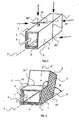
- the present invention relates to the production of conditioned air distribution ducts (1) with a substantially parallelepipedal section, such as that illustrated in FIGS. Figures 1 and 2 with at least one insulating panel (2) comprising at least one insulating layer (3) of mineral wool and preferably of glass wool, said duct (1) having a longitudinal principal axis P.
- insulation duct (1) is intended to convey a conditioning air flow F, the upstream duct being connected to at least one conditioned air source (not shown) and the duct downstream being connected at least one conditioned air distribution mouth (also not shown).
- the air flow F is oriented substantially along the main axis P.
- the minimum requirements for the manufacture and assembly of fiberglass core tubular conduit systems for the forced circulation of air at negative or positive pressures up to 500 Pa and maximum speeds of 10 m / s are defined in a standard.
- the ducts CLIMAVER PLUS and SISTEMA CLIMAVER METAL of the company SAINT GOBAIN ISOVER are suitable for the implementation of the present invention and the respect of the standard because they admit pressures up to 800 Pa and maximum speeds of 18 m / s .
- the duct (1) which is intended to be arranged in a metal duct (not shown) to form a conditioned air transport duct, will be described in more detail below.
- the present disclosure relates more particularly to a method for producing a duct figure, in order to make it possible to achieve at least one change of direction C according to an angle ⁇ , or its complementary angle ⁇ , modifying the main longitudinal axis P , in a primary downstream axis P ', or even in a secondary downstream axis P ", that is to say involving a change of direction simple or with separation of air flow.
- said angle ⁇ is substantially between 30 ° and 60 ° and preferably substantially equal to 45 °.
- the figure 3 illustrates the pressure drop measurements (in Pa) performed on four types of right angle elbows (T1 to T4), of square section 30x30 cm for T1 and T2 and rectangular section 39x32 cm for T3 and T4 depending on the speed air flow (in m / s), T1 and T3 being made according to the prior method and T2 and T4 being manufactured according to the method of this presentation.
- the method of the present invention makes it possible to eliminate the irregularities formed on the inner surface of the duct when a figure is made using the prior method and thus makes it possible to reduce the pressure drops across the duct otherwise generated by these irregularities.
- said change of direction C is made by cutting in a flat panel (2), as illustrated. figure 4 , of each of the faces of said duct (1).
- the faces of the duct which are parallel to the plane comprising said change of direction C each have more than four sides in this plane and preferably six sides for a simple change of direction or eight sides for a double directional change allowing in the end to make a change of direction at right angles. In this way, the sealing of the insulation is even better ensured at the level of the change of direction.
- the change of direction C is made by complete section, that is to say, complete cutting, of an upstream duct (1) into a downstream primary section (1 ') and possibly a downstream secondary section ( 1 ") if the change of direction is double, as well as, possibly, rotation around its axis of the primary section (1 '), see secondary section (1").
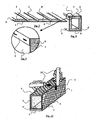
- the conduit (1-1'-1 ") is made from a panel (2) such as that illustrated on the figure 5 .
- the first variant of the process produces about 1.5 m 2 of falls to make two 90 ° elbows of 30x35 cm (approximately), illustrated in gray on the figure 4 , while the second variant produces no drop for the manufacture of the same two figures.
- FIGS. 1 and 2 schematically represent this second variant of implementation of the method from a straight section to obtain a change of direction at an angle ⁇ .
- a tubular duct (1) of rectangular section, on four sides of which is carried out, in a traditional way and by appropriate measures, four straight marks (20, 20 ', 20 ", 20'” ) on the four sides of the duct, which, in the case of lines or marks (20, 20 ") form an angle ⁇ with respect to a transverse line of the relevant face at the corner of the duct, and which, in the case of lines (20 ', 20 ") are parallel to said transverse line of the relevant face.
- conduit (1-1 ') bent at an angle ⁇ illustrated on the figure 2 it suffices to turn the primary section (1 ') by 180 ° and to position the rear edges of the downstream primary section (1') against the front edges of the upstream tubular duct (1).
- the conduit (1-1 ') then forms an obtuse elbow, in other words at an angle ⁇ greater than 90 °, to cause a change of direction of the air flow F.
- the figure 6 illustrates a panel (2) for the realization of the tubular duct (1) according to the first or the second variant of implementation of the method.
- This panel (2) comprises at least one insulating layer (3) of mineral wool and preferably glass wool and has a substantially parallelepipedal shape and flat. It also comprises an outer layer (4) which will be outside the tubular insulation duct (1) when it is formed, and optionally an inner layer (4 ') which will be inside the tubular duct ( 1) when it is formed.
- the outer layer (4) is intended to be substantially brought into contact with the metal wall of the conditioned inventive step transport conduit.
- the outer layer (4) further has a plurality of transverse rectilinear marks (6), oriented perpendicular to said transverse edges (9) and a plurality of longitudinal rectilinear marks (7) oriented in the direction of the longitudinal edges (8).
- the straight marks (5, 6, 7) thus make it possible to calibrate the plate (2) and, as a result, the tubular body (1), so as to facilitate the making of markings prior to cutting and cutting.
- the marks (5) have only been illustrated on one side of the duct (1) on the figure 2 to facilitate reading, but it is obvious that they are present on all sides of the conduit (1).
- FIGS 7, 8 and 9 illustrate an embodiment of a duct (1) from a single plate (2) folded along four longitudinal edges at right angles, according to the second variant of implementation of the method.
- the four pieces of the panel intended to form the faces of the duct each have a right longitudinal edge and an opposite longitudinal edge profiled in a stair step, in other words provided with a rabbet depth equal to the edge of the room it will receive when bending at 90 ° and thickness equal to half the thickness thereof.
- One of the parts further comprises an extension of the outer layer which will be stapled over the other part, as can be seen on the figure 9 .
- the sealing is done with a strip of fabric impregnated with plaster and glue or with an adhesive tape of aluminum.
- the sealing of the ducts is particularly tight, air leakage to the outside of the duct being negligible provided that it was manufactured and assembled correctly.
- the transverse connection of elements to form the ductwork is done by placing the surfaces of two sections of duct in the same plane, stapling the flap of one of the sections on the other (without flap) and sealing the connection using an adhesive tape.
- the transverse edges (9) of the elements to be connected are profiled so as to form a so-called "male” section and another so-called “female". On these transverse edges, the density of the glass wool is much greater, which increases the rigidity of the connection and improves the assembly.
- the cutting panels (2) can be achieved using a circular saw connected to a suction system.
- the circular saw shall be equipped with a device for tilting the angle of cut to allow for perpendicular cuts, cuts at 22.5 ° from the vertical, and cuts at 45 ° or more. other angles.
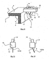
- the cutting of the panels (2) is operated using a particular cutting instrument (10) first illustrated at the figure 10 for the implementation of the second variant.
- This instrument (10) shown in detail Figures 11 to 15 , has a guide surface (12) for sliding on the surface of the panel (2), a handle (14) and two blades (15, 16) located in the same plane and each having a cutting edge (17, 18). .
- These cutting edges (17, 18) are oriented in this plane at inclinations contrary to the guide surface (12).
- the first cutting edge (17), that of the first blade (15) is oriented rearward with respect to the cutting direction and has a height less than the second cutting edge (18), that of the second blade (16). ), which is oriented forward; however, the two blades (15, 16) do not touch each other.
- the first cutting edge (17) has a height less than the total thickness of the panel (2) and the second cutting edge (18) has a height greater than the total thickness of the panel (2).
- the instrument (10) also makes it possible to cut a panel (12), even when the latter is already arranged to form a duct, as can be seen on the figure 13 . Due to the arrangement of the blades (15, 16) and their respective cutting edges (17, 18), it is possible to start cutting a conduit at an angle without causing smudging or delamination.
- the cutting instrument (10) has straight blades (15, 16), that is, oriented perpendicularly to the guide surface (12). This version allows to make straight cuts, like the cuts (20 and 20 ") on the Figures 1 and 2 .
- the cutting instrument (10) has slats (15, 16) inclined, that is to say oriented at an angle ⁇ with respect to the guide surface (12).
- This version makes it possible to make inclined cuts, like the cuts (20 'and 20 "') on the Figures 1 and 2 .
- ⁇ ⁇ .
- the blades (15, 16) are provided with a system for adjusting their inclination with respect to the guide surface (12), or that the blades (15, 16) are removable and cooperate with a rail formed in the guide surface (12), a plurality of rail types imposing different blade inclinations.
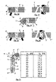
- the cutting line is marked on the outer surface (4) of the duct (1) with the help of the marks (5), as illustrated by FIG. figure 16 and is cut with a tangential circular saw or preferably using the instrument (10), following the imaginary plane passing through the duct perpendicular to the main axis P and passing through this section line.
- the slices inclined at ⁇ ° are preferably made first, before those perpendicular to the surface (4) of the conduit.
- the duct is rotated 180 ° on itself, then is positioned so that axis P 'crosses the axis P of the upstream duct, as can be seen on the figure 18 .
- a bead of glue is applied along the edges to be connected, and this near the inner edge duct.
- the connection area is then sealed, outside and on the perimeter, with an aluminum adhesive tape.
- the ribbon will maintain the shape and rigidity of the fitting, both inside and out.
- the outer surface (4) of the panel comprises a template formed of marks (5) facilitating the drawing of lines that will serve as cutting lines.
- the table of the figure 21 exposes the gaps D 1 between the main duct (1) and the secondary section (1 ") as a function of the minimum length A 1 of the primary section (1 ').
- the inflection is a deviation of the direction of the duct sometimes necessary if one wants to avoid the obstacles present on the right trajectory of the duct.
- the duct section is kept constant throughout its course.
- the method of realizing an inflection is very close to the method of producing a 90 ° elbow.
- the outer surface (4) of the panel comprises a template formed of marks (5) facilitating the drawing of lines that will serve as cutting lines.
- the table of the figure 25 exposes the spacings D 2 between the main duct (1) and the secondary section (1 ") as a function of the minimum length A 2 of the primary section (1 ').
- the outer surface (4) of the panel comprises a template formed of marks (5) facilitating the drawing of lines that will serve as cutting lines.
- the first section constitutes the main section (1), illustrated figure 30
- the second section constitutes the primary section (1 '), illustrated figure 29 , of width B K
- the third section constitutes the tertiary section (1"'), also illustrated figure 29 , of width A K.
- the connection of the continuation of the main section in tertiary section and the branch goes through this line.
- the reduced width at K of the tertiary section (1 "') at the intersection which is reported on the tertiary section (1"') is measured on one side, as shown in FIG. figure 33 and a line inclined 22.5 ° with respect to an imaginary perpendicular section is drawn on the outer surface of the other side, thereby obtaining the measurement of the reduced width b K of the primary section (1 ') which is refer to the primary section (1 ') as shown in figure 31 along a line inclined at 22.5 ° with respect to an imaginary perpendicular section.
- a second section is made at an angle of 22.5 ° with respect to an imaginary perpendicular section to form the secondary section (1 "), the primary section must then be turned 180 °, as for a right angle bend (see point b).
- the measured value d K of this segment must be reported on the main pipe (1), illustrated figure 32 , then the width b K must be reported along a line inclined at 22.5 ° with respect to a transverse of the main duct (1).
- the four sections (1, 1 ', 1 ", 1"') are connected in such a way that the respective axes (P, P ', P ") of the sections (1, 1', 1" ) cut in pairs at a 45 ° angle and the axes of the main (1) and tertiary (1 "') sections are parallel, as shown figure 34 .
- the angle ⁇ between the uppermost axis P and the downstream axis P "of the branch is 90 °.
- Each branch (left, right) is thus formed of a primary section (1 ') and a secondary section (1 "), the secondary sections (1") left and right being respectively derived from the primary sections (1') left and right.
- the two elbows at 90 ° may have different downstream sections, the sum of which is greater than the section of the main duct, their height must however be identical to that of the main section.
- the connection of the two branches goes through this line. From this line, two lines inclined by 22.5 ° are drawn on each side, to obtain the measurements a L and b L which are reported on the branches, as shown in the diagram. figure 39 .
Description
La présente invention se rapporte à un panneau d'isolation pour conduit de distribution d'air conditionnée, ledit panneau d'isolation comportant au moins une âme isolante à base de laine minérale, de préférence de laine de verre, et comportant une couche extérieure par exemple à base d'une fine pellicule d'aluminium.The present invention relates to an insulation panel for conditioned air distribution duct, said insulating panel comprising at least one insulating core based on mineral wool, preferably glass wool, and comprising an outer layer by example based on a thin film of aluminum.
Par exemple, le document
La présente invention concerne plus particulièrement la fabrication dans les bâtiments de conduits pour le transport et la distribution d'air conditionnée. De tels conduits présentent en général une structure métallique composée d'un châssis autoporté et de plaques de métal disposées entre les montants de ce châssis, ainsi qu'à l'intérieur de ce conduit, une isolation fabriquée à partir de panneaux d'isolation. La fabrication de ces conduits de transport et de distribution de l'air conditionnée nécessite de réaliser des changements de direction du conduit, afin d'assurer la distribution de l'air en différents points.The present invention relates more particularly to the manufacture in duct buildings for the transport and distribution of conditioned air. Such ducts generally have a metal structure composed of a self-supporting frame and metal plates disposed between the uprights of this frame, as well as inside this duct, an insulation made from insulating panels. The manufacture of these conduits for transporting and distributing conditioned air requires changes in the direction of the duct, in order to ensure the distribution of air at different points.
L'art antérieur connaît un procédé de fabrication de conduits d'isolation selon lequel on décompose l'angle du changement de direction en un grand nombre d'angles de valeurs inférieures. Ainsi, selon ce procédé, le changement de direction est très progressif et les valeurs intrinsèques du courant d'air ne subissent qu'une légère modification au fur et à mesure que le courant progresse dans le changement de direction.The prior art discloses a method of manufacturing insulating ducts in which the angle of change of direction is decomposed into a large number of lower value angles. Thus, according to this method, the change of direction is very progressive and the intrinsic values of the air flow undergo only a slight change as the current progresses in the change of direction.
Le but de l'invention est de permettre de diminuer les pertes de charges engendrées dans les changements de direction réalisés selon le procédé de l'art antérieur, tout en facilitant la réalisation des changements de direction.The object of the invention is to reduce the pressure losses generated in the direction changes made according to the method of the prior art, while facilitating the realization of changes of direction.
La présente invention a ainsi pour objet un panneau d'isolation pour conduit de distribution d'air conditionnée selon la revendication 1.The present invention thus relates to an insulation panel for a conditioned air distribution duct according to
Ce panneau d'isolation comporte une âme isolante à base de laine minérale, de préférence de laine de verre, et comporte une couche extérieure par exemple à base d'une fine pellicule d'aluminium. Ce panneau présente en outre, sur une face extérieure une pluralité de marques rectilignes et obliques par rapport à une direction longitudinale dudit panneau, lesdites marques formant dieux faisceaux d'inclinaisons contraires et orientées selon un angle γ par rapport à ladite direction longitudinale.This insulation panel comprises an insulating core based on mineral wool, preferably glass wool, and has an outer layer for example based on a thin aluminum film. This panel further has, on an outer face a plurality of rectilinear marks and oblique with respect to a longitudinal direction of said panel, said marks forming godeux bundles of opposite inclinations and oriented at an angle γ relative to said longitudinal direction.
Ledit angle γ est, est égal à 67,5°.Said angle γ is equal to 67.5 °.
Ladite face extérieure du panneau présente en outre, de préférence, une pluralité de marques rectilignes transversales orientées perpendiculairement à ladite direction longitudinale. Elle présente une pluralité de marques rectilignes longitudinales orientées parallèlement à ladite direction longitudinale.Said outer face of the panel further preferably has a plurality of transverse rectilinear marks oriented perpendicularly to said longitudinal direction. It has a plurality of longitudinal rectilinear marks oriented parallel to said longitudinal direction.
Lesdites marques rectilignes obliques, et éventuellement lesdites marques rectilignes transversales et/ou lesdites marques rectilignes longitudinales sont, de préférence, matérialisées au moins à proximité de bords longitudinaux et de préférence sur toute la surface de la face extérieure.Said oblique rectilinear marks, and optionally said transverse rectilinear marks and / or said longitudinal rectilinear marks, are preferably materialized at least in the vicinity of longitudinal edges and preferably over the entire surface of the outer face.
Lesdites marques rectilignes obliques, et éventuellement lesdites marques rectilignes transversales et/ou lesdites marques rectilignes longitudinales sont matérialisées sur la surface de la face extérieure de la couche extérieure du panneau.Said oblique rectilinear marks, and optionally said transverse rectilinear marks and / or said longitudinal rectilinear marks are materialized on the surface of the outer face of the outer layer of the panel.
Dans une variante, lesdites marques rectilignes transversales et/ou lesdites marques rectilignes longitudinales coupent lesdites marques rectilignes obliques en des points où des marques rectilignes longitudinales d'inclinaisons contraires se coupent.In a variant, said transverse rectilinear marks and / or said longitudinal rectilinear marks intersect said oblique rectilinear marks at points where longitudinal rectilinear marks of opposite inclinations intersect.
Les marques de guidage obliques, transversales et rectilignes permettent ainsi de faciliter la fabrication des conduits d'isolation et de gagner du temps et de la précision lors de la réalisation des tracés et des coupes sur site.The oblique, transverse and rectilinear guide marks thus make it easier to manufacture insulation conduits and save time and precision when drawing and cutting on site.
Les marques sont dessinées de façon à coïncider sur les quatre faces du conduit une fois les coupes nécessaires effectuées, sans aucun décalage, à condition toutefois que les mesures intérieures soient des multiples de 5 cm.The marks are drawn so as to coincide on all four sides of the duct once the necessary cuts have been made, without any offset, provided that the internal measurements are multiples of 5 cm.
La présente invention se rapporte également à un conduit de distribution présentant une section sensiblement parallélépipédique, ledit panneau étant constitué à partir d'au moins un panneau d'isolation selon l'invention.The present invention also relates to a distribution duct having a substantially parallelepipedal section, said panel being constituted from at least one insulation panel according to the invention.
Ce conduit présente, de préférence, un axe principal longitudinal P et au moins un changement de direction selon un angle β, modifiant l'axe principal longitudinal P en un axe aval P', P", ledit angle β étant compris sensiblement entre 30° et 60° et de préférence égal sensiblement à 45°.This duct preferably has a longitudinal main axis P and at least one change of direction at an angle β, modifying the main longitudinal axis P in a downstream axis P ', P ", said angle β being substantially between 30 ° and 60 ° and preferably equal to substantially 45 °.
Le présent exposé se rapporte également un procédé de fabrication d'un conduit de distribution à section sensiblement parallélépipédique à l'aide d'au moins un panneau d'isolation selon l'invention.The present disclosure also relates to a method of manufacturing a distribution duct with a substantially parallelepiped section using at least one insulation panel according to the invention.
Selon ce procédé de fabrication, ledit conduit présente un axe principal longitudinal P et au moins un changement de direction selon un angle β, modifiant l'axe principal longitudinal P en un axe aval P', P", ledit angle β étant compris sensiblement entre 30° et 60° et de préférence égal sensiblement à 45°.According to this manufacturing method, said duct has a main longitudinal axis P and at least one change of direction at an angle β, modifying the main longitudinal axis P in a downstream axis P ', P ", said angle β being substantially between 30 ° and 60 ° and preferably equal to substantially 45 °.
Ce procédé permet ainsi de réaliser une multitude de figures avec une diminution importante des pertes de charge par rapport aux figures de l'art antérieur.This method thus makes it possible to produce a multitude of figures with a significant reduction in pressure drops compared to the figures of the prior art.
On appelle « figure » tout conduit non droit résultant d'un changement de direction de son axe principal avec ou sans séparation du flux d'air (par exemple : coude d'angle supérieur à 90° ou égal à 90°, inflexion, ramification simple selon un angle droit avec ou sans modification de la section du conduit principal, ramification double à angle droit,...).The term "figure" refers to any duct that is not straight resulting from a change of direction of its principal axis with or without separation of the air flow (for example: upper corner elbow at 90 ° or equal to 90 °, inflection, simple branching at a right angle with or without modification of the section of the main duct, double branch at right angles, ...).
On désigne par ramification la figure qui donne lieu à une bifurcation du flux d'air circulant dans le réseau, en modifiant la direction d'une partie du flux circulant (ramification simple ou en « r ») ou en modifiant la direction de la totalité du flux circulant (ramification double ou en « pantalon »). Pour assurer une distribution adéquate, la branche amont d'une ramification est toujours celle de plus grande section.Branching is the figure that gives rise to a bifurcation of the air flow circulating in the network, by modifying the direction of a part of the circulating flow (simple branching or in "r") or by modifying the direction of the totality circulating flow (double branching or in "pants"). To ensure adequate distribution, the upstream branch of a branch is always that of larger section.
Par « direction transversale » au sens de la présente invention, on entend une direction orientée perpendiculairement à la direction longitudinale générale du conduit.By "transverse direction" in the sense of the present invention is meant a direction oriented perpendicular to the general longitudinal direction of the conduit.
Selon une première variante de mise en oeuvre, ledit changement de direction est réalisé par découpage dans un panneau plat de chacune des faces dudit conduit.According to a first variant of implementation, said change of direction is made by cutting in a flat panel of each of the faces of said duct.
Dans cette première variante, les faces du conduit qui sont parallèles au plan comprenant ledit changement de direction présentent, de préférence, chacune plus de quatre côtés dans ce plan et de préférence six côtés ou huit côtés.In this first variant, the faces of the duct which are parallel to the plane comprising said change of direction preferably each have more than four sides in this plane and preferably six sides or eight sides.
Selon une deuxième variante de mise en oeuvre, ledit changement de direction est réalisé par section complète d'un conduit en un tronçon primaire aval et éventuellement un tronçon secondaire aval, ainsi que, éventuellement, rotation autour de son axe principal dudit tronçon primaire, ou du tronçon secondaire.According to a second variant of implementation, said change of direction is made by complete section of a duct in a downstream primary section and possibly a downstream secondary section, as well as, optionally, rotation around its main axis of said primary section, or of the secondary section.
Selon cette deuxième variante, ladite section est, de préférence, réalisée sur deux faces parallèles au plan comprenant ledit changement de direction selon un angle β, par rapport à une direction transversale de ces faces et sur les deux autres faces selon une direction transversale de ces faces.According to this second variant, said section is preferably made on two faces parallel to the plane comprising said change of direction at an angle β, with respect to a transverse direction of these faces and on the other two faces in a transverse direction of these directions. faces.
Le découpage selon la première variante ou la section selon la deuxième variante est, de préférence, opéré à l'aide d'un instrument de découpage présentant deux lames situées dans un même plan, les bords tranchant respectivement desdites lames étant orientés selon des inclinaisons contraires et le premier bord tranchant présentant une hauteur inférieure au deuxième bord tranchant selon la direction générale de découpage ou de section.The cutting according to the first variant or the section according to the second variant is preferably carried out using a cutting instrument having two blades located in the same plane, the cutting edges respectively of said blades being oriented in opposite inclinations. and the first cutting edge having a height less than the second cutting edge in the general direction of cutting or section.
Avec la méthode antérieure de construction, pour fabriquer une figure (un coude, une bifurcation, ...), on pratique des ouvertures dans la face du panneau qui reste à l'intérieur du conduit (puisque c'est la seule façon de le plier suivant la courbure souhaitée). L'intérieur du conduit comporte donc des irrégularités, même si ces faces sont couvertes d'un ruban Ces irrégularités soumettent l'air traversant le conduit à de multiples changements de direction, créent des tourbillons et occasionnent donc des pertes de charge.With the previous method of construction, to make a figure (a bend, a bifurcation, ...), we make openings in the face of the panel which remains inside the conduit (since it is the only way of the fold according to the desired curvature). The interior of the duct therefore has irregularities, even if these faces are covered with a ribbon These irregularities subject the air passing through the duct to multiple changes of direction, create vortices and therefore cause losses.
Avantageusement, la méthode permet d'éliminer ces irrégularités et donc de réduire les pertes de charge à travers le conduit. En outre, elle permet d'éviter les dépôts de poussières, saletés, etc. produits par ces irrégularités.Advantageously, the method makes it possible to eliminate these irregularities and thus to reduce the pressure drops across the duct. In addition, it avoids deposits of dust, dirt, etc. produced by these irregularities.
Avantageusement également, la méthode assure une meilleure rigidité des figures que la méthode antérieure, puisqu'elle utilise au départ un conduit droit, la pièce la plus résistante du réseau.Advantageously also, the method ensures a better rigidity of the figures than the previous method, since it initially uses a straight duct, the most resistant part of the network.
Avantageusement enfin, la méthode permet de diminuer d'une manière importante le nombre de chutes de matière isolante inutilisées, et la surface totale de ces chutes, ce qui facilite l'entretien du chantier et permet de réaliser des économies de matière.Advantageously, finally, the method makes it possible to significantly reduce the number of unused insulating material falls, and the total surface area of these falls, which facilitates the maintenance of the building site and makes it possible to save material.
Le présent exposé se rapporte également à un instrument de découpage pour le découpage d'au moins un panneau d'isolation selon l'invention, cet instrument présentant deux lames situées dans un même plan, les bords tranchant respectivement desdites lames étant orientés selon des inclinaisons contraires et le premier bord tranchant présentant une hauteur inférieure au deuxième bord tranchant selon la direction générale de découpage.The present disclosure also relates to a cutting instrument for cutting at least one insulating panel according to the invention, this instrument having two blades located in the same plane, the cutting edges respectively of said blades being oriented according to inclinations contrary and the first cutting edge having a height less than the second cutting edge in the general direction of cutting.
Dans une variante, lesdites lames sont orientées selon un angle δ par rapport à une surface de guidage.In a variant, said blades are oriented at an angle δ with respect to a guide surface.
Dans une version préférée, γ = δ.In a preferred version, γ = δ.
De préférence, le premier bord tranchant présente une hauteur inférieure à l'épaisseur totale du panneau et le deuxième bord tranchant présente une hauteur supérieure à l'épaisseur totale du panneau.Preferably, the first cutting edge has a height less than the total thickness of the panel and the second cutting edge has a height greater than the total thickness of the panel.
L'instrument de découpage assure une coupe propre et précise, suivant l'inclinaison adaptée à la formation des figures, d'où un raccord parfait entre les pièces coupées formant les figures. Ces pièces restent intimement unies grâce à la colle, assurant un joint parfait équivalent à celui unissant deux tronçons droits.The cutting instrument ensures a clean and precise cut, according to the inclination adapted to the formation of the figures, hence a perfect connection between the cut pieces forming the figures. These pieces remain intimately united thanks to the glue, ensuring a perfect joint equivalent to that joining two straight sections.
La présente invention sera mieux comprise à la lecture de la description détaillée ci-après d'exemples de réalisation non limitatifs et des figures ci-jointes :
- La
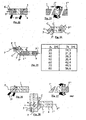
figure 1 illustre une vue de profil d'un conduit tubulaire droit pour la réalisation d'un changement de direction selon un angle β ; - La
figure 2 illustre une vue de profil du conduit tubulaire de lafigure 1 après réalisation du changement de direction selon l'angle β; - La
figure 3 est un tableau illustrant les différences de perte de charge entre les changements de direction réalisés selon le procédé de l'art antérieur et le procédé pour deux types de section de conduit : 30x30 cm et 39x32 cm ; - La
figure 4 illustre une vue de face d'un panneau marqué et près à être découpé pour la réalisation de deux changements de direction pour réaliser un changement de direction à angle droit selon la première variante du procédé ; - La
figure 5 illustre une vue de face d'un panneau près à être marqué et à être découpé pour la réalisation de deux changements de direction pour réaliser un changement de direction à angle droit selon la deuxième variante du procédé ; - La
figure 6 illustre une vue en perspective d'un panneau selon l'invention pour la réalisation d'un conduit tubulaire ; - Les
figures 7, 8 et 9 illustrent la réalisation d'un conduit tubulaire à partir du panneau de lafigure 6 replié à angle droit selon quatre arêtes longitudinales, lafigure 9 étant une vue de détail de lafigure 8 ; - La
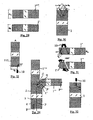
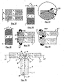
figure 10 est une vue en perspective de l'opération de découpage d'un conduit tubulaire pour la réalisation d'un changement de direction selon la deuxième variante du procédé ; - La
figure 11 illustre une vue en coupe transversale d'un panneau pendant l'attaque du bord extérieur du panneau à l'aide d'un instrument de découpage ; - La
figure 12 illustre une vue en coupe transversale d'un panneau pendant l'attaque du bord inférieur du panneau à l'aide d'un instrument de découpage ; - La
figure 13 illustre une vue en perspective partielle d'un conduit tubulaire avant l'attaque du bord du panneau à l'aide d'un instrument de découpage ; - La
figure 14 illustre une vue de face d'une première version de l'instrument de découpage à lames droites et lafigure 15 illustre une vue de face d'une seconde version de l'instrument de découpage à lames inclinées ; - Les
figures 16 à 18 illustrent la réalisation d'un changement de direction selon un angle α, complémentaire de l'angle β, non droit dans un conduit tubulaire selon la deuxième variante de mise en oeuvre du procédé ; - Les
figures 19 à 21 illustrent la réalisation d'un changement de direction selon un angle α, complémentaire de l'angle β, droit dans un conduit tubulaire selon la deuxième variante de mise en oeuvre du procédé, lafigure 21 étant complétée d'un tableau exposant les écartements D1 entre le conduit principal et le tronçon secondaire en fonction de la longueur minimale A1 du tronçon primaire ; - Les
figures 22 à 25 illustrent la réalisation d'un changement de direction réalisant une déviation sans changement d'orientation générale dans un conduit tubulaire selon la deuxième variante de mise en oeuvre du procédé, lafigure 25 étant complétée d'un tableau exposant les écartements D2 entre le conduit principal et le tronçon secondaire en fonction de la longueur minimale A2 du tronçon primaire ; - Les
figures 26 à 28 illustrent la réalisation d'un changement de direction réalisant une ramification simple selon un angle α droit dans un conduit tubulaire selon la deuxième variante de mise en oeuvre du procédé , sans modification de la section du conduit principal ; - Les
figures 29 à 34 illustrent la réalisation d'un changement de direction réalisant une ramification simple selon un angle α droit dans un conduit tubulaire selon la deuxième variante de mise en oeuvre du procédé avec réduction de la section du conduit principal ; et - Les
figures 35 à 41 illustrent la réalisation d'un changement de direction réalisant une ramification double selon deux angles α droits dans un conduit tubulaire selon la deuxième variante de mise en oeuvre du procédé.
- The
figure 1 illustrates a profile view of a straight tubular duct for performing a change of direction at an angle β; - The
figure 2 illustrates a profile view of the tubular duct of thefigure 1 after realization of the change of direction according to the angle β; - The
figure 3 is a table illustrating the differences in pressure drop between the changes of direction made by the method of the prior art and the method for two types of duct section: 30x30 cm and 39x32 cm; - The
figure 4 illustrates a front view of a sign marked and ready to be cut for making two changes of direction to make a change of direction at right angles according to the first variant of the method; - The
figure 5 illustrates a front view of a panel close to be marked and cut for making two changes of direction to achieve a change of direction at right angles according to the second variant of the method; - The
figure 6 illustrates a perspective view of a panel according to the invention for producing a tubular duct; - The
Figures 7, 8 and 9 illustrate the realization of a tubular duct from the panel of thefigure 6 folded at right angles along four longitudinal edges, thefigure 9 being a detail view of thefigure 8 ; - The
figure 10 is a perspective view of the cutting operation of a tubular duct for performing a change of direction according to the second variant of the method; - The
figure 11 illustrates a cross-sectional view of a panel during the attack of the outer edge of the panel with a cutting instrument; - The
figure 12 illustrates a cross-sectional view of a panel during the attack of the lower edge of the panel using a cutting instrument; - The
figure 13 illustrates a partial perspective view of a tubular duct before the edge of the panel is attacked by means of a cutting instrument; - The
figure 14 illustrates a front view of a first version of the straight-blade cutting instrument and thefigure 15 illustrates a front view of a second version of the slanted blade cutting instrument; - The
Figures 16 to 18 illustrate the realization of a change of direction according to an angle α, complementary to the angle β, not straight in a tubular conduit according to the second alternative embodiment of the method; - The
Figures 19 to 21 illustrate the realization of a change of direction according to an angle α, complementary to the angle β, right in a tubular conduit according to the second variant of implementation of the method, thefigure 21 being supplemented by a table showing the spacings D 1 between the main duct and the secondary section as a function of the minimum length A 1 of the primary section; - The
Figures 22 to 25 illustrate the realization of a change of direction realizing a deviation without change of general orientation in a tubular conduit according to the second variant of implementation of the method, thefigure 25 being supplemented by a table showing the spacings D 2 between the main duct and the secondary section as a function of the minimum length A 2 of the primary section; - The
Figures 26 to 28 illustrate the realization of a change of direction achieving a simple branching at an angle α right in a tubular conduit according to the second variant of implementation of the method, without changing the section of the main conduit; - The
Figures 29 to 34 illustrate the realization of a change of direction achieving a simple branching at an angle α right in a tubular conduit according to the second variant of implementation of the method with reduction of the section of the main conduit; and - The
Figures 35 to 41 illustrate the realization of a change of direction achieving a double branching at two right angles α in a tubular conduit according to the second variant of implementation of the method.
Il est précisé que les proportions entre les divers éléments représentés ne sont pas rigoureusement respectées dans ces figures afin d'en faciliter la lecture.It is specified that the proportions between the various elements represented are not rigorously respected in these figures in order to facilitate their reading.
Il est également précisé que les directions avant-arrière s'entendent par rapport au sens du flux d'air, en considérant que la conduite est fabriquée en partant de la source du flue d'air.It is also specified that the front-rear directions are in relation to the direction of the air flow, considering that the pipe is manufactured starting from the source of the air stream.
La présente invention se rapporte à la réalisation de conduits de distribution d'air conditionnée (1) à section sensiblement parallélépipédique, tel que celui illustré sur les
Les conditions minimales de fabrication et de montage de systèmes de conduits tubulaire à âme en laine de verre pour la circulation forcée d'air à des pressions négatives ou positives allant jusqu'à 500 Pa et des vitesses maximales de 10 m/s sont définies dans une norme. Les conduits CLIMAVER PLUS et SISTEMA CLIMAVER METAL de la société SAINT GOBAIN ISOVER conviennent à la mise en oeuvre de la présente invention et au respect de la norme car ils admettent des pressions allant jusqu'à 800 Pa et des vitesses maximales de 18 m/s. Le conduit (1) qui est destiné à être disposé dans un conduit métallique (non illustré) afin de former un conduit de transport d'air conditionné, sera décrit plus en détail ci-après.The minimum requirements for the manufacture and assembly of fiberglass core tubular conduit systems for the forced circulation of air at negative or positive pressures up to 500 Pa and maximum speeds of 10 m / s are defined in a standard. The ducts CLIMAVER PLUS and SISTEMA CLIMAVER METAL of the company SAINT GOBAIN ISOVER are suitable for the implementation of the present invention and the respect of the standard because they admit pressures up to 800 Pa and maximum speeds of 18 m / s . The duct (1) which is intended to be arranged in a metal duct (not shown) to form a conditioned air transport duct, will be described in more detail below.
Le présent exposé se rapporte plus particulièrement à un procédé d'élaboration d'une figure de conduit, afin de permettre de réaliser au moins un changement de direction C selon un angle α, ou son angle complémentaire β, modifiant l'axe principal longitudinal P, en un axe aval primaire P', voire en un axe aval secondaire P", c'est-à-dire faisant intervenir un changement de direction simple ou avec séparation de flux d'air.The present disclosure relates more particularly to a method for producing a duct figure, in order to make it possible to achieve at least one change of direction C according to an angle α, or its complementary angle β, modifying the main longitudinal axis P , in a primary downstream axis P ', or even in a secondary downstream axis P ", that is to say involving a change of direction simple or with separation of air flow.
En effet, lors de l'installation de conduits de transport d'air conditionnée dans un bâtiment, il peut arriver très exceptionnellement que le conduit soit parfaitement rectiligne sur toute sa longueur, sans aucun changement de direction, ni par rapport à l'horizontale, ni par rapport à la verticale entre la source d'air conditionné et la bouche d'évacuation ; mais dans l'immense majorité des cas, la fabrication dans un bâtiment d'un conduit de transport et de distribution d'air conditionnée oblige à réaliser des changements de directions du conduit et donc de son isolation pour opérer la distribution de l'air dans différentes pièces contiguës et à différents étages.Indeed, during the installation of transport of conditioned air in a building, it can happen very exceptionally that the duct is perfectly rectilinear over all its length, without any change of direction, nor with respect to the horizontal, nor with respect to the vertical between the source of air conditioning and the evacuation mouth; but in the vast majority of cases, the manufacture in a building of a conduit for the transport and distribution of conditioned air makes it necessary to make changes of directions of the duct and thus of its insulation to operate the distribution of air in different rooms contiguous and at different levels.
Dans l'art antérieur, il est exposé que pour réaliser un changement de direction dans un conduit de distribution, il est préférable de décomposer ce changement de direction en une multitude de sections droites agencées de manière à ce que leurs axes principaux respectifs ne soit écartés du précédant et du suivant que de quelques degrés.In the prior art, it is explained that in order to achieve a change of direction in a distribution duct, it is preferable to break this change of direction into a multitude of straight sections arranged so that their respective main axes are not separated. from the preceding and the following only a few degrees.
De cette manière, on pensait que le flux d'air transitant à l'intérieur du conduit subirait alors le moins de modifications possibles de ses caractéristiques intrinsèques.In this way, it was thought that the flow of air passing through the duct would then undergo the least possible modification of its intrinsic characteristics.
Or, il apparaît d'une manière surprenante que c'est en réalité l'inverse : pour modifier le moins possible les caractéristiques intrinsèques du flux d'air transitant à l'intérieur du conduit, il est préférable de décomposer le changement de direction en un plus petit possible nombre de sections droites et d'agencer ces sections de manière à ce que leurs axes principaux respectifs soient écartés du précédant et du suivant du plus grand angle possible ; Toutefois, l'angle droit et les angles aigus (inférieurs à 90°) sont à proscrire.Surprisingly, it is actually the opposite: to modify as little as possible the intrinsic characteristics of the flow of air passing inside the duct, it is preferable to decompose the change of direction into a smaller possible number of straight sections and arranging these sections so that their respective main axes are spaced from the preceding and the following of the widest possible angle; However, the right angle and acute angles (less than 90 °) should not be used.
Ainsi, ledit angle β est compris sensiblement entre 30° et 60° et de préférence égal sensiblement à 45°.Thus, said angle β is substantially between 30 ° and 60 ° and preferably substantially equal to 45 °.
A titre d'exemple, lorsque les pertes de charge dans un coude à angle droit de section 30x30 cm, sont de 8 Pa pour un conduit fabriqué selon la méthode antérieure à une vitesse de l'air de 7 m/s, elles ne sont que de 5 Pa pour un conduit fabriqué selon la méthode du présent exposé avec une section et une vitesse d'air identiques.For example, when the pressure drops in a right angle elbow of 30x30 cm section, are 8 Pa for a duct manufactured according to the prior method at an air speed of 7 m / s, they are not than 5 Pa for a duct manufactured according to the method of this presentation with an identical section and air velocity.
La
Cette figure montre que les pertes de charge dans un coude de section donnée fabriqué selon la méthode de la présente invention (Courbe T2 en trait interrompu et cercle vide ; Courbe T4 en trait interrompu et carré vide) sont inférieures à celles du coude de même section donnée fabriqué selon la méthode antérieure (courbe T1 en trait continu, triangle plein ; Courbe T3 en trait continu, losange plein), quelle que soit la vitesse du flux à l'intérieur du coude.This figure shows that the pressure drop in a given section bend made according to the method of the present invention (curved T2 curve and empty circle curve T4 dashed and empty square) are lower than those of the elbow of the same section. data manufactured according to the previous method (curve T1 in continuous line, solid triangle; curve T3 in solid line, full rhombus), whatever the speed of the flow inside the elbow.
La méthode du présent exposé permet d'éliminer les irrégularités formées à la surface intérieure du conduit lorsque l'on réalise une figure en utilisant la méthode antérieure et permet ainsi de réduire les pertes de charge à travers le conduit sinon engendrées par ces irrégularités.The method of the present invention makes it possible to eliminate the irregularities formed on the inner surface of the duct when a figure is made using the prior method and thus makes it possible to reduce the pressure drops across the duct otherwise generated by these irregularities.
La fabrication des diverses figures du réseau de conduits commence par le tracé, sur le panneau, des différentes pièces qui seront par la suite coupées et assemblées à l'aide d'un nombre réduit d'outils légers et faciles à manipuler.The manufacture of the various figures of the ductwork begins with the drawing, on the panel, of the different pieces which will be cut and assembled with the help of a small number of light and easy to handle tools.
Le procédé de fabrication de ces figures présente deux variantes de mise en oeuvre et d'utilisation du panneau (2) selon l'invention.The manufacturing method of these figures presents two variants of implementation and use of the panel (2) according to the invention.
Dans la première variante de mise en oeuvre du procédé, ledit changement de direction C est réalisé par découpage dans un panneau plat (2), tel que celui illustré
Dans cette première variante, les faces du conduit qui sont parallèles au plan comprenant ledit changement de direction C présentent chacune plus de quatre côtés dans ce plan et de préférence six côtés pour un simple changement de direction ou huit côtés pour un double changement de direction permettant au final de réaliser un changement de direction à angle droit. De cette manière, l'étanchéité de l'isolation est encore mieux assurée au niveau du changement de direction.In this first variant, the faces of the duct which are parallel to the plane comprising said change of direction C each have more than four sides in this plane and preferably six sides for a simple change of direction or eight sides for a double directional change allowing in the end to make a change of direction at right angles. In this way, the sealing of the insulation is even better ensured at the level of the change of direction.
Dans la deuxième variante, le changement de direction C est réalisé par section complète, c'est-à-dire découpage complet, d'un conduit (1) amont en un tronçon primaire aval (1') et éventuellement un tronçon secondaire aval (1") si le changement de direction est double, ainsi que, éventuellement, rotation autour de son axe du tronçon primaire (1'), voir du tronçon secondaire (1"). Le conduit (1-1'-1") est réalisé à partir d'un panneau (2) tel que celui illustré sur la
Il est à noter que la première variante du procédé produit environ 1,5 m2 de chutes pour fabriquer deux coudes à 90° de 30x35 cm (environ), illustrées en grisé sur la
Les
Selon cet exemple, on part d'un conduit tubulaire (1), de section rectangulaire, sur quatre faces duquel on effectue, de façon traditionnelle et par des mesures adéquates, quatre marques rectilignes (20, 20', 20", 20'") sur les quatre faces du conduit, qui, dans le cas des lignes ou marques (20, 20") forment un angle β par rapport à une ligne transversale de la face concernée au niveau coin du conduit, et qui, dans le cas des lignes (20', 20"), sont parallèles à ladite ligne transversale de la face concernée. L'angle β est l'angle complémentaire de α, c'est-à-dire que α + β = 180°.According to this example, one starts from a tubular duct (1), of rectangular section, on four sides of which is carried out, in a traditional way and by appropriate measures, four straight marks (20, 20 ', 20 ", 20'" ) on the four sides of the duct, which, in the case of lines or marks (20, 20 ") form an angle β with respect to a transverse line of the relevant face at the corner of the duct, and which, in the case of lines (20 ', 20 ") are parallel to said transverse line of the relevant face. The angle β is the complementary angle α, that is to say that α + β = 180 °.
Les coupes selon les lignes de marquage (20', 20"') sont réalisées perpendiculairement à la face du conduit concernée, mais les coupes selon les ligne de marquage (20, 20") sont réalisée selon un angle γ =90° - β. Ces coupes permettent de réaliser un tronçon de conduit primaire aval (1') dans le conduit tubulaire (1).The sections along the marking lines (20 ', 20 "') are made perpendicular to the face of the duct concerned, but the cuts along the marking lines (20, 20") are made at an angle γ = 90 ° - β . These cuts make it possible to produce a portion of downstream primary duct (1 ') in the tubular duct (1).
Pour obtenir le conduit (1-1') coudé selon un angle α illustré sur la
La
Ce panneau (2) comporte au moins une couche isolante (3) en laine minérale et de préférence en laine de verre et présente une forme sensiblement parallélépipédique et plate. Il comporte également une couche extérieure (4) qui sera à l'extérieur du conduit tubulaire d'isolation (1) lorsque celui-ci sera formé, et éventuellement une couche intérieure (4') qui sera à l'intérieur du conduit tubulaire (1) lorsque celui-ci sera formé. La couche extérieure (4) est destinée à être mise sensiblement en contact avec la paroi métallique du conduit de transport d'activité inventive conditionnée.This panel (2) comprises at least one insulating layer (3) of mineral wool and preferably glass wool and has a substantially parallelepipedal shape and flat. It also comprises an outer layer (4) which will be outside the tubular insulation duct (1) when it is formed, and optionally an inner layer (4 ') which will be inside the tubular duct ( 1) when it is formed. The outer layer (4) is intended to be substantially brought into contact with the metal wall of the conditioned inventive step transport conduit.
La couche extérieure (4) présente sur sa face extérieure une pluralité de marques rectilignes (5) et obliques par rapport aux bords longitudinaux (8) dudit panneau, lesdites marques formant deux faisceaux de lignes, un faisceau étant incliné selon un angle γ = 67,5° par rapport auxdits bords longitudinaux (8) et l'autre faisceau étant orienté d'un angle contraire de -γ par rapport auxdits bords longitudinaux (8).The outer layer (4) has on its outer face a plurality of rectilinear marks (5) and oblique with respect to the longitudinal edges (8) of said panel, said marks forming two bundles of lines, a bundle being inclined at an angle γ = 67 5 ° relative to said longitudinal edges (8) and the other beam being oriented at an opposite angle of -γ relative to said longitudinal edges (8).
La couche extérieure (4) présente en outre une pluralité de marques rectilignes transversales (6), orientées perpendiculairement auxdits bords transversaux (9) et une pluralité de marques rectilignes longitudinales (7) orientées selon la direction des bords longitudinaux (8).The outer layer (4) further has a plurality of transverse rectilinear marks (6), oriented perpendicular to said transverse edges (9) and a plurality of longitudinal rectilinear marks (7) oriented in the direction of the longitudinal edges (8).
Les marques rectilignes (5, 6, 7) permettent ainsi de calibrer la plaque (2) et, de ce fait, le corps tubulaire (1), de façon à faciliter la réalisation des marquages préalable aux découpages et les découpages.The straight marks (5, 6, 7) thus make it possible to calibrate the plate (2) and, as a result, the tubular body (1), so as to facilitate the making of markings prior to cutting and cutting.
Ces marques (5, 6, 7) servent donc à faciliter à la fois le marquage et le mouvement de l'outil de coupe pour la réalisation des découpages.These marks (5, 6, 7) serve to facilitate both the marking and the movement of the cutting tool for the realization of cutting.
Les marques (5) n'ont été illustrée que sur une seule face du conduit (1) sur la
Les
Comme on peut le voir sur la
Pour certains panneaux, le scellage se fait à l'aide d'une bande de tissu imprégnée de plâtre et de colle ou à l'aide d'un ruban adhésif en aluminium.For some panels, the sealing is done with a strip of fabric impregnated with plaster and glue or with an adhesive tape of aluminum.
Le scellage des conduits est particulièrement étanche, les fuites d'air vers l'extérieur du conduit étant négligeables à condition que celui-ci ait été fabriqué et assemblé correctement.The sealing of the ducts is particularly tight, air leakage to the outside of the duct being negligible provided that it was manufactured and assembled correctly.
Le raccord transversal d'éléments pour former le réseau de conduits se fait en plaçant les surfaces de deux tronçons de conduit dans un même plan, en agrafant le rabat d'un des tronçons sur l'autre (sans rabat) et en scellant le raccord à l'aide d'un ruban adhésif. Les bords transversaux (9) des éléments à raccorder sont profilés de façon à former une section dite « mâle » et une autre dite « femelle ». Sur ces bords transversaux, la densité de la laine de verre est beaucoup plus importante, ce qui accroît la rigidité du raccord et améliore le montage.The transverse connection of elements to form the ductwork is done by placing the surfaces of two sections of duct in the same plane, stapling the flap of one of the sections on the other (without flap) and sealing the connection using an adhesive tape. The transverse edges (9) of the elements to be connected are profiled so as to form a so-called "male" section and another so-called "female". On these transverse edges, the density of the glass wool is much greater, which increases the rigidity of the connection and improves the assembly.
Le découpage des panneaux (2), soit à plat, soit formés en conduit, peut être réalisé à l'aide d'une scie circulaire reliée à un système d'aspiration. La scie circulaire sera dotée d'un dispositif permettant d'incliner l'angle de coupe, afin de permettre d'effectuer des coupes perpendiculaires, des coupes à 22,5° par rapport à la verticale et des coupes à 45°, voire à d'autres angles.The cutting panels (2), either flat or duct formed, can be achieved using a circular saw connected to a suction system. The circular saw shall be equipped with a device for tilting the angle of cut to allow for perpendicular cuts, cuts at 22.5 ° from the vertical, and cuts at 45 ° or more. other angles.
Dans une version préférée, le découpage des panneaux (2), soit à plat, soit formés en conduit, est opéré à l'aide d'un instrument de découpage (10) particulier illustré tout d'abord à la
Le premier bord tranchant (17), celui de la première lame (15), est orienté vers l'arrière au regard de la direction de découpage et présente une hauteur inférieure au deuxième bord tranchant (18), celui de la deuxième lame (16), qui est orienté vers l'avant ; toutefois, les deux lames (15, 16) ne se touchent pas. Le premier bord tranchant (17) présente une hauteur inférieure à l'épaisseur totale du panneau (2) et le deuxième bord tranchant (18) présente une hauteur supérieure à l'épaisseur totale du panneau (2).The first cutting edge (17), that of the first blade (15) is oriented rearward with respect to the cutting direction and has a height less than the second cutting edge (18), that of the second blade (16). ), which is oriented forward; however, the two blades (15, 16) do not touch each other. The first cutting edge (17) has a height less than the total thickness of the panel (2) and the second cutting edge (18) has a height greater than the total thickness of the panel (2).
Ainsi, comme on peut le voir sur la
L'instrument (10) permet également de découper un panneau (12), même lorsque celui-ci est déjà agencé pour former un conduit, comme on peut le voir sur la
Dans une première version illustrée
Dans une deuxième version illustrée
Il est possible de prévoir que les lames (15, 16) soient munies d'un système permettant de régler leur inclinaison par rapport à la surface de guidage (12), ou que les lames (15, 16) soient amovibles et coopèrent avec un rail ménagé dans la surface de guidage (12), une pluralité de types de rail imposant des inclinaisons de lames différentes.It is possible to provide that the blades (15, 16) are provided with a system for adjusting their inclination with respect to the guide surface (12), or that the blades (15, 16) are removable and cooperate with a rail formed in the guide surface (12), a plurality of rail types imposing different blade inclinations.
On détaille par la suite des constructions de changements de direction à l'aide de la deuxième variante du procédé.Details of changes of direction are subsequently described using the second variant of the method.
On évitera toujours de construire des changements de direction, (coudes ou tout autre type de figure), caractérisés par des courbes pures (circulaires) dans la mesure où ceux-ci nécessitent davantage de coupes du revêtement intérieur du conduit, ce qui affaiblit la figure et peut éventuellement endommager la laine de verre en cas de mauvaise exécution de la coupe.It will always be avoided to construct changes of direction (elbows or any other type of figure), characterized by pure curves (circular) insofar as these require more cuts of the lining of the conduit, which weakens the figure. and can possibly damage the glass wool in case of bad execution of the cut.
Pour réaliser un coude d'angle α supérieur à 90°, on marque la ligne de coupe sur la surface extérieure (4) du conduit (1) en s'aidant des marques (5), comme l'illustre la
Comme on peut le voir sur la
Comme il n'est pas possible d'effectuer un emboîtement mâle-femelle ni d'utiliser de rabats pour agrafer les deux pièces constitutives du coude, on applique un cordon de colle le long des bords à raccorder, et ce à proximité du bord intérieur du conduit. On scellé ensuite la zone de raccord, à l'extérieur et sur le périmètre, à l'aide d'un ruban adhésif en aluminium. Le ruban maintiendra la forme et la rigidité du raccord, tant à l'intérieur qu'à l'extérieur.As it is not possible to perform a male-female interlock or use flaps to staple the two components of the elbow, a bead of glue is applied along the edges to be connected, and this near the inner edge duct. The connection area is then sealed, outside and on the perimeter, with an aluminum adhesive tape. The ribbon will maintain the shape and rigidity of the fitting, both inside and out.
Pour réduire les pertes de charge, il est conseillé de prévoir des déflecteurs dans les coudes dont l'angle α est inférieur à 135°. On fixera la plaque qui maintient les déflecteurs ou les ailettes à l'intérieur du conduit au moyen de vis autotaraudeuses et de rondelles mises en place par l'extérieur.To reduce the pressure losses, it is advisable to provide deflectors in the elbows whose angle α is less than 135 °. Fix the plate that holds the baffles or fins inside the duct by means of self-tapping screws and washers put in place from the outside.
Pour réaliser un coude d'angle α à 90°, on marque sur la surface extérieure (4) du conduit (1), comme l'illustre la
La surface extérieure (4) du panneau comporte un gabarit formé de marques (5) facilitant le tracé des droites qui serviront de lignes de coupe.The outer surface (4) of the panel comprises a template formed of marks (5) facilitating the drawing of lines that will serve as cutting lines.
On coupe à la scie circulaire tangentielle ou de préférence en utilisant l'instrument (10), le conduit en suivant les lignes, en accordant une attention particulière à l'inclinaison de la coupe (perpendiculaire à la surface du conduit pour les lignes formant un angle de 22,5 °, et incliné de 22,5° pour les lignes transversales). On obtient ainsi la première des trois pièces qui formeront le coude : le conduit principal (1).Tangential circular cutting or preferably using the instrument (10), the duct following the lines, paying particular attention to the inclination of the cut (perpendicular to the duct surface for lines forming a angle of 22.5 °, and inclined 22.5 ° for transverse lines). This gives the first of the three pieces that will form the elbow: the main duct (1).
A une distance de plus de 15 cm de la première section, on réalise la même opération, mais suivant un angle de -22,5° par rapport à une section perpendiculaire imaginaire. On obtient ainsi les trois tronçons (1,1', 1") de conduit.At a distance of more than 15 cm from the first section, the same operation is carried out, but at an angle of -22.5 ° with respect to an imaginary perpendicular section. This gives the three sections (1,1 ', 1 ") of duct.
On tourne ensuite de 180° sur elle-même la pièce intermédiaire du conduit formée par le tronçon primaire (1'), comme illustré
On accordera une attention toute particulière à la précision de la mesure de l'angle de 22,5°, sous peine d'obtenir des coudes de moins de 90° (coudes fermés) ou de plus de 90° (coudes ouverts).Particular attention will be paid to the precision of the 22.5 ° angle measurement, otherwise elbows of less than 90 ° (closed elbows) or more than 90 ° (open elbows) will occur.
Il n'est pas nécessaire, dans ce cas, de prévoir de déflecteurs.It is not necessary, in this case, to provide baffles.
Le scellage des pièces se fait comme dans le paragraphe précédent.The sealing of the pieces is done as in the previous paragraph.
Le tableau de la
L'inflexion est une déviation de la direction du conduit parfois nécessaire si l'on veut éviter les obstacles présents sur la trajectoire droite du conduit. La section du conduit est maintenue constante sur tout son parcours.The inflection is a deviation of the direction of the duct sometimes necessary if one wants to avoid the obstacles present on the right trajectory of the duct. The duct section is kept constant throughout its course.
La méthode de réalisations d'une inflexion est très proche de la méthode de réalisation d'un coude à 90°.The method of realizing an inflection is very close to the method of producing a 90 ° elbow.
Pour réaliser une inflexion, on marque sur la surface extérieure (4) du conduit (1), comme l'illustre la
La surface extérieure (4) du panneau comporte un gabarit formé de marques (5) facilitant le tracé des droites qui serviront de lignes de coupe.The outer surface (4) of the panel comprises a template formed of marks (5) facilitating the drawing of lines that will serve as cutting lines.
On coupe à la scie circulaire tangentielle ou de préférence en utilisant l'instrument (10), le conduit en suivant les lignes, en accordant une attention particulière à l'inclinaison de la coupe (perpendiculaire à la surface du conduit pour les lignes formant un angle de 22,5°, et incliné de 22,5° pour les lignes transversales). On obtient ainsi la première des trois pièces qui formeront l'inflexion : le conduit principal (1).Tangential circular cutting or preferably using the instrument (10), the duct following the lines, paying particular attention to the inclination of the cut (perpendicular to the duct surface for lines forming a angle of 22.5 °, and inclined 22.5 ° for transverse lines). We thus obtain the first of the three pieces that will form the inflection: the main duct (1).
A une distance de plus de 20 cm de la première section, on réalise la même opération, mais suivant un angle identique de +22,5°. On obtient ainsi les trois tronçons (1, 1', 1") de conduit.At a distance of more than 20 cm from the first section, the same operation is carried out, but at an identical angle of + 22.5 °. This gives the three sections (1, 1 ', 1 ") of duct.
On tourne ensuite de 180° sur elle-même la pièce intermédiaire du conduit formée par le tronçon primaire (1'), comme illustré
On accordera une attention toute particulière à la précision de la mesure de l'angle de 22,5 °, sous peine d'obtenir une perte du parallélisme entre l'axe le plus amont P et l'axe le plus aval P".Particular attention will be paid to the precision of the 22.5 ° angle measurement, otherwise there will be a loss of parallelism between the upstream axis P and the downstream axis P ".
Il n'est pas nécessaire, dans ce cas, de prévoir de déflecteurs.It is not necessary, in this case, to provide baffles.
Le scellage des pièces se fait comme dans le paragraphe précédent.The sealing of the pieces is done as in the previous paragraph.
Le tableau de la
Pour réaliser une ramification simple selon un angle α droit sans modification de la section du conduit principal, on marque sur la surface extérieure (4) du conduit (1), comme l'illustre la
La surface extérieure (4) du panneau comporte un gabarit formé de marques (5) facilitant le tracé des droites qui serviront de lignes de coupe.The outer surface (4) of the panel comprises a template formed of marks (5) facilitating the drawing of lines that will serve as cutting lines.
On coupe à la scie circulaire tangentielle ou de préférence en utilisant l'instrument (10), le conduit en suivant les lignes, en accordant une attention particulière à l'inclinaison de la coupe (perpendiculaire à la surface du conduit pour les lignes formant un angle de 45°, et incliné de 45° pour les lignes transversales). On obtient ainsi la première section de la pièce qui formera la ramification.Tangential circular cutting or preferably using the instrument (10), the duct following the lines, paying particular attention to the inclination of the cut (perpendicular to the duct surface for lines forming a angle of 45 °, and inclined 45 ° for transverse lines). This gives the first section of the piece that will form the branch.
A une distance de plus de 5 cm de la première section, on réalise la même opération, mais suivant un angle de 22,5° par rapport à une section perpendiculaire imaginaire. On obtient ainsi les trois tronçons (1,1', 1") de conduit.At a distance of more than 5 cm from the first section, the same operation is carried out, but at an angle of 22.5 ° with respect to an imaginary perpendicular section. This gives the three sections (1,1 ', 1 ") of duct.
On tourne ensuite de 180° sur elle-même la pièce finale du conduit formée par le tronçon secondaire (1"), comme illustré
On accordera une attention toute particulière à la précision de la mesure des angles de 45° et de 22,5°, sous peine d'obtenir des ramifications de moins de 90° (ramifications fermées) ou de plus de 90° (ramifications ouvertes).Particular attention will be given to the accuracy of 45 ° and 22.5 ° angles, otherwise branching less than 90 ° (closed ramifications) or greater than 90 ° (open ramifications) .
Il n'est pas nécessaire, dans ce cas, de prévoir de déflecteurs.It is not necessary, in this case, to provide baffles.
Le scellage des pièces se fait comme dans le paragraphe précédent.The sealing of the pieces is done as in the previous paragraph.
Pour réaliser une ramification simple selon un angle α droit avec modification de la section du conduit principal, on utilise trois tronçons droits. Le premier tronçon constitue le tronçon principal (1), illustré
La première étape consiste à tracer une ligne longitudinale imaginaire et passant par l'intersection des courbes de rayon r1 = AK et r2 = BK sur la surface extérieure du tronçon principal (1), comme illustré
A partir de cette ligne, on mesure d'un côté la largeur réduite aK du tronçon tertiaire (1"') au niveau de l'intersection que l'on reporte sur le tronçon tertiaire (1"'), comme illustré sur la
Une fois les mesures aK et bK reportées, on joint les points intérieurs par deux droites 1 inclinées à 45° jusqu'aux extrémités longitudinales des tronçons.Once the measurements K and b K reported, we join the inner points by two
Sur le tronçon primaire (1'), à une distance de plus de 15 cm de la première section, on réalise une seconde section, suivant un angle de 22,5° par rapport à une section perpendiculaire imaginaire pour former le tronçon secondaire (1"), le tronçon primaire devant alors être tourné sur lui-même de 180 °, comme pour un coude à angle droit (cf. point b).On the primary section (1 '), at a distance of more than 15 cm from the first section, a second section is made at an angle of 22.5 ° with respect to an imaginary perpendicular section to form the secondary section (1 "), the primary section must then be turned 180 °, as for a right angle bend (see point b).
Sur le tronçon primaire (1') la valeur mesurée dK de ce segment, doit être reportée sur le conduit principal (1), illustré
Pour former la ramification, on raccorde les quatre tronçons (1, 1', 1", 1"') de manières à ce que les axes respectifs (P, P', P") des tronçons (1, 1', 1") se coupent deux à deux selon un angle à 45 ° et que les axes du tronçon principal (1) et du tronçon tertiaire (1"') soient parallèles, comme illustré
On accordera une attention toute particulière à la précision de la mesure des angles de 45° et de 22,5 °, sous peine d'obtenir une ramification de moins de 90° (ramification fermée) ou de plus de 90° (ramification ouverte).Particular attention will be paid to the accuracy of 45 ° and 22.5 ° angles, otherwise branching less than 90 ° (closed branching) or more than 90 ° (open branching) .
Il n'est pas nécessaire, dans ce cas, de prévoir de déflecteurs.It is not necessary, in this case, to provide baffles.
Le scellage des pièces se fait comme dans les paragraphes précédents.The sealing of the pieces is done as in the previous paragraphs.
Les coudes des embranchements de cette figure couramment appelée « pantalon » sont réalisés comme on l'a décrit dans le paragraphe b précédent. Chaque embranchement (gauche, droit) est ainsi formé d'un tronçon primaire (1') et d'un tronçon secondaire (1"), les tronçons secondaires (1") gauche et droit étant issu respectivement des tronçons primaires (1') gauche et droit. Les deux coudes à 90° (gauche, droit) peuvent présenter des sections avales différentes, dont la somme est supérieure à la section du conduit principal, leur hauteur devant toutefois être identique à celle du tronçon principal.The bends of the branches of this figure commonly called "pants" are made as described in paragraph b above. Each branch (left, right) is thus formed of a primary section (1 ') and a secondary section (1 "), the secondary sections (1") left and right being respectively derived from the primary sections (1') left and right. The two elbows at 90 ° (left, right) may have different downstream sections, the sum of which is greater than the section of the main duct, their height must however be identical to that of the main section.
La première étape consiste à tracer une ligne longitudinale et passant par l'intersection des courbes de rayon r1 = AL et r2 = BL, comme illustré
Une fois les mesures aL et bL reportées selon deux droites inclinées à 22,5° sur chaque embranchement, on joint les points intérieurs par deux droites inclinées à 45 ° jusqu'aux extrémités des embranchements. La différence entre les valeurs de ceux segments, doit être reportée sur le conduit principal (1), illustré
On vérifiera facilement que si la somme des sections intérieures des embranchements est égale à la section intérieure du conduit principal, cette différence a pour valeur 0, et il suffit de couper les bords des pièces à 45 ° dans la zone de raccord des embranchements. Il est conseillé d'effectuer cette coupe en premier, avant les coupes correspondant à aL et bL.It will be easily verified that if the sum of the inner sections of the branches is equal to the inner section of the main duct, this difference has the
Comme précédemment, il est bien sûr nécessaire d'entourer la partie extérieure des raccords de ruban adhésif et de coller la partie intérieure des raccords du conduit.As before, it is of course necessary to surround the outer portion of the tape and tape the inner portion of the conduit fittings.
Claims (3)
- An insulating panel (2) for a conditioned-air distribution duct (1), said insulating panel (2) comprising an insulating core (3) based on mineral wool, preferably on rock wool, and comprising an exterior layer (4) for example based on a thin skin of aluminum, characterized in that on the exterior face of the exterior layer it has a plurality of marks (5) that are straight and oblique with respect to a longitudinal direction of said panel, said marks forming two sets of opposing inclinations oriented at an angle γ equal to 67.5° with respect to said longitudinal direction, and in that the said exterior face also has a plurality of longitudinal straight marks (7) oriented parallel to said longitudinal direction.
- The insulating panel (2) as claimed in claim 1, characterized in that said exterior face also has a plurality of transverse straight marks (6) oriented at right angles to said longitudinal direction.
- A distribution duct (1) having a substantially parallelepipedal cross section, the duct being made from at least one insulating panel (2) as claimed in any one of the preceding claims.
Priority Applications (1)
| Application Number | Priority Date | Filing Date | Title |
|---|---|---|---|
| SI200331603T SI1532391T2 (en) | 2002-06-24 | 2003-06-18 | Insulation panel for supply duct |
Applications Claiming Priority (5)
| Application Number | Priority Date | Filing Date | Title |
|---|---|---|---|
| ES201600001U | 2002-06-24 | ||
| ES200201601U ES1052378Y (en) | 2002-06-24 | 2002-06-24 | PANEL FOR AIR CONDITIONING DISTRIBUTION DUCTS. |
| ES200201600U ES1052377Y (en) | 2002-06-24 | 2002-06-24 | CUTTING TOOL FOR AIR CONDITIONING DUCTS. |
| ES201600000U | 2002-06-24 | ||
| PCT/FR2003/001854 WO2004001277A1 (en) | 2002-06-24 | 2003-06-18 | Insulation panel for supply duct |
Publications (3)
| Publication Number | Publication Date |
|---|---|
| EP1532391A1 EP1532391A1 (en) | 2005-05-25 |
| EP1532391B1 EP1532391B1 (en) | 2009-03-18 |
| EP1532391B2 true EP1532391B2 (en) | 2019-03-06 |
Family
ID=30001915
Family Applications (1)
| Application Number | Title | Priority Date | Filing Date |
|---|---|---|---|
| EP03760735.5A Expired - Lifetime EP1532391B2 (en) | 2002-06-24 | 2003-06-18 | Insulation panel for supply duct |
Country Status (15)
| Country | Link |
|---|---|
| US (1) | US7798176B2 (en) |
| EP (1) | EP1532391B2 (en) |
| CN (1) | CN100516622C (en) |
| AR (1) | AR040470A1 (en) |
| AT (1) | ATE426127T2 (en) |
| AU (1) | AU2003260599A1 (en) |
| BR (1) | BRPI0312016B1 (en) |
| CA (1) | CA2490055C (en) |
| DE (1) | DE60326733D1 (en) |
| DK (1) | DK1532391T4 (en) |
| ES (1) | ES2324530T5 (en) |
| PT (1) | PT1532391E (en) |
| RU (1) | RU2305815C2 (en) |
| SI (1) | SI1532391T2 (en) |
| WO (1) | WO2004001277A1 (en) |
Families Citing this family (12)
| Publication number | Priority date | Publication date | Assignee | Title |
|---|---|---|---|---|
| EP2045505A1 (en) * | 2007-10-02 | 2009-04-08 | Logstor A/S | Bendable pre-insulated pipeline assembly |
| FR2986255A1 (en) * | 2012-02-01 | 2013-08-02 | Egis Conseil Batiments | Sheath pipe for use in e.g. ventilation duct, in high-rise building, has set of modules including set of panels, where set of modules is adapted to geometry of section of pipe, and is manufactured from specific materials |
| US8667995B1 (en) * | 2012-05-23 | 2014-03-11 | Carl Fanelli | Insulated ducts and insulated ductworks |
| ES1077290Y (en) * | 2012-06-06 | 2012-09-21 | Saint Gobain Cristaleria S L | Air duct panel |
| US9528261B2 (en) | 2013-01-09 | 2016-12-27 | Vita Nonwovens, Llc | Synthetic fiber insulation with facing |
| ITMI20131540A1 (en) * | 2013-09-19 | 2015-03-20 | Carpenteria Leggera Aerotecnica C L A S R L | SOUNDPROOF DEVICE, PARTICULARLY FOR VENTILATION CHANNELS. |
| FR3033021B1 (en) * | 2015-02-19 | 2017-11-24 | Saint Gobain Isover Iberica S L | ENVELOPE COVERED WITH REPERES |
| US10578335B2 (en) * | 2018-04-04 | 2020-03-03 | Daniel Frank Nolin | Insulated air transfer duct |
| ES2911848R1 (en) * | 2019-02-25 | 2022-07-19 | Saint Gobain Isover Iberica S L | MINERAL WOOL OR SIMILAR DUCTING TOOL |
| ES2780998B2 (en) * | 2019-02-25 | 2022-06-24 | Saint Gobain Isover Iberica S L | CUTTING DEVICE FOR CUTTING MINERAL WOOL OR SIMILAR SHEETS |
| FR3114045B1 (en) | 2020-09-14 | 2022-12-23 | Saint Gobain Isover Iberica S L | PANEL FOR AIR CONDITIONING DUCT |
| GB202018461D0 (en) * | 2020-11-24 | 2021-01-06 | Knauf Insulation Doo Skofja Loka | Insulating panel |
Citations (12)
| Publication number | Priority date | Publication date | Assignee | Title |
|---|---|---|---|---|
| US3092529A (en) † | 1955-07-01 | 1963-06-04 | Owens Corning Fiberglass Corp | Duct or conduit blank |
| DE1190391B (en) † | 1958-02-20 | 1965-04-01 | Gewerk Eisenhuette Westfalia | Conveyor with stationary channel, especially for coal |
| US4064626A (en) † | 1976-09-09 | 1977-12-27 | Cbs Inc. | Cutter for sheet material |
| US4064627A (en) † | 1976-12-15 | 1977-12-27 | Vincent Zanfini | Carpet cutter |
| FR2409755A1 (en) † | 1977-11-25 | 1979-06-22 | Buzas Andre | MEDICINES BASED ON NEW INDOLO (2,3-A) QUINOLIZIDINES |
| US4179808A (en) † | 1978-05-10 | 1979-12-25 | Johns-Manville Corporation | Cutting guide tool for fabrication of air duct transitions and method of its use |
| US4183379A (en) † | 1975-12-03 | 1980-01-15 | Mutz Corp. | Duct board assembly |
| GB2189273A (en) † | 1986-04-16 | 1987-10-21 | Saint Gobain Isover | A method of installing between supports such as rafters a mineral fibre material provided in roll form, a mineral fibre strip suitable for carrying out the method and a method of producing the said mineral fibre strip |
| US5040297A (en) † | 1989-12-01 | 1991-08-20 | Malco Products, Inc. | Fiberglass panel cutter with adjustable square and duct knife |
| US5750225A (en) † | 1995-05-26 | 1998-05-12 | Compac Corporation | Laminated vapor barrier |
| US5783268A (en) † | 1993-08-11 | 1998-07-21 | Knauf Fiber Glass Gmbh | High air velocity duct board having minimal turbulence |
| US20010003993A1 (en) † | 1999-12-13 | 2001-06-21 | Faverio Louis P. | Thermal insulating panels |
Family Cites Families (5)
| Publication number | Priority date | Publication date | Assignee | Title |
|---|---|---|---|---|
| FR2409855A1 (en) * | 1977-11-24 | 1979-06-22 | Chollet Jacques | Prefabricated refractory elements for lagging or sleeves - which can easily be bent to fit round objects for protection against fire |
| US5172731A (en) * | 1989-02-13 | 1992-12-22 | Soltech, Inc. | Thermal insulation blanket |
| FR2740804B1 (en) * | 1995-11-03 | 1997-12-05 | Saint Gobain Isover | VENTILATION SHEATH AND INSULATING PANEL USED FOR ITS INTERNAL COATING |
| DK0772009T3 (en) * | 1995-11-03 | 2002-09-16 | Saint Gobain Isover | Ventilation duct and insulating panel for covering this |
| CA2226595C (en) * | 1998-01-12 | 2003-12-02 | Emco Limited | Composite vapour barrier panel |
-
2003
- 2003-06-18 RU RU2005101418/06A patent/RU2305815C2/en active
- 2003-06-18 EP EP03760735.5A patent/EP1532391B2/en not_active Expired - Lifetime
- 2003-06-18 WO PCT/FR2003/001854 patent/WO2004001277A1/en not_active Application Discontinuation
- 2003-06-18 CN CNB038201062A patent/CN100516622C/en not_active Expired - Lifetime
- 2003-06-18 DK DK03760735.5T patent/DK1532391T4/en active
- 2003-06-18 BR BRPI0312016A patent/BRPI0312016B1/en active IP Right Grant
- 2003-06-18 AU AU2003260599A patent/AU2003260599A1/en not_active Abandoned
- 2003-06-18 US US10/517,616 patent/US7798176B2/en active Active
- 2003-06-18 AT AT03760735T patent/ATE426127T2/en active
- 2003-06-18 ES ES03760735T patent/ES2324530T5/en not_active Expired - Lifetime
- 2003-06-18 CA CA2490055A patent/CA2490055C/en not_active Expired - Lifetime
- 2003-06-18 SI SI200331603T patent/SI1532391T2/en unknown
- 2003-06-18 PT PT03760735T patent/PT1532391E/en unknown
- 2003-06-18 DE DE60326733T patent/DE60326733D1/en not_active Expired - Lifetime
- 2003-06-24 AR AR20030102245A patent/AR040470A1/en active IP Right Grant
Patent Citations (12)
| Publication number | Priority date | Publication date | Assignee | Title |
|---|---|---|---|---|
| US3092529A (en) † | 1955-07-01 | 1963-06-04 | Owens Corning Fiberglass Corp | Duct or conduit blank |
| DE1190391B (en) † | 1958-02-20 | 1965-04-01 | Gewerk Eisenhuette Westfalia | Conveyor with stationary channel, especially for coal |
| US4183379A (en) † | 1975-12-03 | 1980-01-15 | Mutz Corp. | Duct board assembly |
| US4064626A (en) † | 1976-09-09 | 1977-12-27 | Cbs Inc. | Cutter for sheet material |
| US4064627A (en) † | 1976-12-15 | 1977-12-27 | Vincent Zanfini | Carpet cutter |
| FR2409755A1 (en) † | 1977-11-25 | 1979-06-22 | Buzas Andre | MEDICINES BASED ON NEW INDOLO (2,3-A) QUINOLIZIDINES |
| US4179808A (en) † | 1978-05-10 | 1979-12-25 | Johns-Manville Corporation | Cutting guide tool for fabrication of air duct transitions and method of its use |
| GB2189273A (en) † | 1986-04-16 | 1987-10-21 | Saint Gobain Isover | A method of installing between supports such as rafters a mineral fibre material provided in roll form, a mineral fibre strip suitable for carrying out the method and a method of producing the said mineral fibre strip |
| US5040297A (en) † | 1989-12-01 | 1991-08-20 | Malco Products, Inc. | Fiberglass panel cutter with adjustable square and duct knife |
| US5783268A (en) † | 1993-08-11 | 1998-07-21 | Knauf Fiber Glass Gmbh | High air velocity duct board having minimal turbulence |
| US5750225A (en) † | 1995-05-26 | 1998-05-12 | Compac Corporation | Laminated vapor barrier |
| US20010003993A1 (en) † | 1999-12-13 | 2001-06-21 | Faverio Louis P. | Thermal insulating panels |
Also Published As
| Publication number | Publication date |
|---|---|
| CN1678863A (en) | 2005-10-05 |
| CA2490055C (en) | 2011-10-18 |
| US7798176B2 (en) | 2010-09-21 |
| ATE426127T2 (en) | 2009-04-15 |
| WO2004001277A1 (en) | 2003-12-31 |
| DK1532391T3 (en) | 2009-06-29 |
| DK1532391T4 (en) | 2019-06-24 |
| EP1532391A1 (en) | 2005-05-25 |
| PT1532391E (en) | 2009-06-25 |
| RU2005101418A (en) | 2005-09-20 |
| US20060096652A1 (en) | 2006-05-11 |
| SI1532391T1 (en) | 2009-08-31 |
| ES2324530T3 (en) | 2009-08-10 |
| AU2003260599A1 (en) | 2004-01-06 |
| BR0312016A (en) | 2005-03-22 |
| EP1532391B1 (en) | 2009-03-18 |
| RU2305815C2 (en) | 2007-09-10 |
| SI1532391T2 (en) | 2019-06-28 |
| CA2490055A1 (en) | 2003-12-31 |
| ES2324530T5 (en) | 2019-10-25 |
| AR040470A1 (en) | 2005-04-06 |
| BRPI0312016B1 (en) | 2015-10-20 |
| DE60326733D1 (en) | 2009-04-30 |
| CN100516622C (en) | 2009-07-22 |
Similar Documents
| Publication | Publication Date | Title |
|---|---|---|
| EP1532391B2 (en) | Insulation panel for supply duct | |
| EP2085488B1 (en) | Vorrichtung zum Blasen von Gas auf eine Fläche von durchlaufendem Bandmaterial | |
| FR2976820A1 (en) | FILTERING ELEMENT WITH GUIDE WELLS | |
| CA2703836A1 (en) | Non-metallic raceway for wiring and fiber optic cable and method of forming raceway | |
| EP1893901B1 (en) | Support for shuttering and passing through a conduit, cable and a flexible hose | |
| FR2501847A1 (en) | PLATE INFRASTRUCTURE FOR TABLECLOTH HEAT EXCHANGER | |
| EP2140120A2 (en) | Method for making an acoustic treatment coating including a cellular structure with a complex shape, and acoustic treatment coating thus obtained | |
| WO2019025719A1 (en) | Tube for a heat exchanger having disturbance device | |
| EP1817535A1 (en) | Heat exchange insert for a heat exchange device | |
| EP4283806A2 (en) | Element for connecting wire-mesh cable-tray sections | |
| KR100972446B1 (en) | Insulation panel for a conditioned?air distribution duct, distribution duct, method for manufacturing the distribution duct, and cutting instrument for cutting the insulation panel | |
| FR2982181A1 (en) | METHOD FOR BENDING PARTICULARLY TUBULAR PROFILES | |
| WO2016097639A1 (en) | Lateral aerator and ventilation duct provided with at least one such aerator | |
| FR3097015A1 (en) | Turbojet engine comprising grids for the formation of an inversion flow. | |
| EP4269900A1 (en) | Diffuser conduit for diffusing air conditioning | |
| FR2984929A1 (en) | DEVICE FOR COLLECTING RAINWATER WATER | |
| FR2916782A3 (en) | Connection box's shell for e.g. U-shaped multi-strand connecting rod in edifice construction field, has cuts of specific mm length projecting from openings, whose diameter corresponds to small diameter of rods and is of specific mm | |
| EP3748097A1 (en) | Metal frame for prefabricated drywall panels | |
| FR2827031A1 (en) | Flexible duct e.g. for ventilation system has spiral reinforcing wire of flat section embedded in the wall | |
| EP3916169A1 (en) | Bracing accessory for lining a wall | |
| CA2451830A1 (en) | Strip for a packing module, corresponding module and installation | |
| EP4330583A1 (en) | Connection device bent at multiple angles | |
| FR3033399A3 (en) | AIR CONVEYOR FOR HEAT PUMP | |
| FR3079016A1 (en) | AERAULIC CONNECTION | |
| FR2991755A3 (en) | PANEL FOR AIR CONDUITS |
Legal Events
| Date | Code | Title | Description |
|---|---|---|---|
| PUAI | Public reference made under article 153(3) epc to a published international application that has entered the european phase |
Free format text: ORIGINAL CODE: 0009012 |
|
| 17P | Request for examination filed |
Effective date: 20041209 |
|
| AK | Designated contracting states |
Kind code of ref document: A1 Designated state(s): AT BE BG CH CY CZ DE DK EE ES FI FR GB GR HU IE IT LI LU MC NL PT RO SE SI SK TR |
|
| AX | Request for extension of the european patent |
Extension state: AL LT LV MK |
|
| DAX | Request for extension of the european patent (deleted) | ||
| 17Q | First examination report despatched |
Effective date: 20080416 |
|
| GRAP | Despatch of communication of intention to grant a patent |
Free format text: ORIGINAL CODE: EPIDOSNIGR1 |
|
| GRAS | Grant fee paid |
Free format text: ORIGINAL CODE: EPIDOSNIGR3 |
|
| GRAA | (expected) grant |
Free format text: ORIGINAL CODE: 0009210 |
|
| AK | Designated contracting states |
Kind code of ref document: B1 Designated state(s): AT BE BG CH CY CZ DE DK EE ES FI FR GB GR HU IE IT LI LU MC NL PT RO SE SI SK TR |
|
| REG | Reference to a national code |
Ref country code: GB Ref legal event code: FG4D Free format text: NOT ENGLISH |
|
| REG | Reference to a national code |
Ref country code: CH Ref legal event code: EP |
|
| REG | Reference to a national code |
Ref country code: IE Ref legal event code: FG4D Free format text: LANGUAGE OF EP DOCUMENT: FRENCH |
|
| REF | Corresponds to: |
Ref document number: 60326733 Country of ref document: DE Date of ref document: 20090430 Kind code of ref document: P |
|
| REG | Reference to a national code |
Ref country code: RO Ref legal event code: EPE |
|
| REG | Reference to a national code |
Ref country code: PT Ref legal event code: SC4A Free format text: AVAILABILITY OF NATIONAL TRANSLATION Effective date: 20090618 |
|
| REG | Reference to a national code |
Ref country code: DK Ref legal event code: T3 |
|
| REG | Reference to a national code |
Ref country code: SE Ref legal event code: TRGR |
|
| REG | Reference to a national code |
Ref country code: GR Ref legal event code: EP Ref document number: 20090401533 Country of ref document: GR |
|
| REG | Reference to a national code |
Ref country code: ES Ref legal event code: FG2A Ref document number: 2324530 Country of ref document: ES Kind code of ref document: T3 |
|
| PG25 | Lapsed in a contracting state [announced via postgrant information from national office to epo] |
Ref country code: EE Free format text: LAPSE BECAUSE OF FAILURE TO SUBMIT A TRANSLATION OF THE DESCRIPTION OR TO PAY THE FEE WITHIN THE PRESCRIBED TIME-LIMIT Effective date: 20090318 |
|
| PG25 | Lapsed in a contracting state [announced via postgrant information from national office to epo] |
Ref country code: SK Free format text: LAPSE BECAUSE OF FAILURE TO SUBMIT A TRANSLATION OF THE DESCRIPTION OR TO PAY THE FEE WITHIN THE PRESCRIBED TIME-LIMIT Effective date: 20090318 |
|
| PLBI | Opposition filed |
Free format text: ORIGINAL CODE: 0009260 |
|
| PLAX | Notice of opposition and request to file observation + time limit sent |
Free format text: ORIGINAL CODE: EPIDOSNOBS2 |
|
| 26 | Opposition filed |
Opponent name: KNAUF INSULATION TECHNOLOGY SPRL Effective date: 20091217 |
|
| PG25 | Lapsed in a contracting state [announced via postgrant information from national office to epo] |
Ref country code: MC Free format text: LAPSE BECAUSE OF NON-PAYMENT OF DUE FEES Effective date: 20090630 |
|
| REG | Reference to a national code |
Ref country code: CH Ref legal event code: PL |
|
| NLR1 | Nl: opposition has been filed with the epo |
Opponent name: KNAUF INSULATION TECHNOLOGY SPRL |
|
| PG25 | Lapsed in a contracting state [announced via postgrant information from national office to epo] |
Ref country code: CH Free format text: LAPSE BECAUSE OF NON-PAYMENT OF DUE FEES Effective date: 20090630 Ref country code: LI Free format text: LAPSE BECAUSE OF NON-PAYMENT OF DUE FEES Effective date: 20090630 |
|
| PLAF | Information modified related to communication of a notice of opposition and request to file observations + time limit |
Free format text: ORIGINAL CODE: EPIDOSCOBS2 |
|
| REG | Reference to a national code |
Ref country code: HU Ref legal event code: AG4A Ref document number: E007282 Country of ref document: HU |
|
| PLBB | Reply of patent proprietor to notice(s) of opposition received |
Free format text: ORIGINAL CODE: EPIDOSNOBS3 |
|
| PG25 | Lapsed in a contracting state [announced via postgrant information from national office to epo] |
Ref country code: GR Free format text: LAPSE BECAUSE OF NON-PAYMENT OF DUE FEES Effective date: 20100107 |
|
| PG25 | Lapsed in a contracting state [announced via postgrant information from national office to epo] |
Ref country code: LU Free format text: LAPSE BECAUSE OF NON-PAYMENT OF DUE FEES Effective date: 20090618 |
|
| PG25 | Lapsed in a contracting state [announced via postgrant information from national office to epo] |
Ref country code: CY Free format text: LAPSE BECAUSE OF FAILURE TO SUBMIT A TRANSLATION OF THE DESCRIPTION OR TO PAY THE FEE WITHIN THE PRESCRIBED TIME-LIMIT Effective date: 20090318 |
|
| PLAY | Examination report in opposition despatched + time limit |
Free format text: ORIGINAL CODE: EPIDOSNORE2 |
|
| PLBC | Reply to examination report in opposition received |
Free format text: ORIGINAL CODE: EPIDOSNORE3 |
|
| APBM | Appeal reference recorded |
Free format text: ORIGINAL CODE: EPIDOSNREFNO |
|
| APBP | Date of receipt of notice of appeal recorded |
Free format text: ORIGINAL CODE: EPIDOSNNOA2O |
|
| APAH | Appeal reference modified |
Free format text: ORIGINAL CODE: EPIDOSCREFNO |
|
| APBM | Appeal reference recorded |
Free format text: ORIGINAL CODE: EPIDOSNREFNO |
|
| APBP | Date of receipt of notice of appeal recorded |
Free format text: ORIGINAL CODE: EPIDOSNNOA2O |
|
| APBQ | Date of receipt of statement of grounds of appeal recorded |
Free format text: ORIGINAL CODE: EPIDOSNNOA3O |
|
| REG | Reference to a national code |
Ref country code: FR Ref legal event code: PLFP Year of fee payment: 14 |
|
| REG | Reference to a national code |
Ref country code: FR Ref legal event code: PLFP Year of fee payment: 15 |
|
| PLAB | Opposition data, opponent's data or that of the opponent's representative modified |
Free format text: ORIGINAL CODE: 0009299OPPO |
|
| R26 | Opposition filed (corrected) |
Opponent name: KNAUF INSULATION TECHNOLOGY SPRL Effective date: 20091217 |
|
| APBU | Appeal procedure closed |
Free format text: ORIGINAL CODE: EPIDOSNNOA9O |
|
| REG | Reference to a national code |
Ref country code: FR Ref legal event code: PLFP Year of fee payment: 16 |
|
| PUAH | Patent maintained in amended form |
Free format text: ORIGINAL CODE: 0009272 |
|
| STAA | Information on the status of an ep patent application or granted ep patent |
Free format text: STATUS: PATENT MAINTAINED AS AMENDED |
|
| 27A | Patent maintained in amended form |
Effective date: 20190306 |
|
| AK | Designated contracting states |
Kind code of ref document: B2 Designated state(s): AT BE BG CH CY CZ DE DK EE ES FI FR GB GR HU IE IT LI LU MC NL PT RO SE SI SK TR |
|
| REG | Reference to a national code |
Ref country code: DE Ref legal event code: R102 Ref document number: 60326733 Country of ref document: DE |
|
| REG | Reference to a national code |
Ref country code: SE Ref legal event code: RPEO |
|
| REG | Reference to a national code |
Ref country code: NL Ref legal event code: FP |
|
| REG | Reference to a national code |
Ref country code: DK Ref legal event code: T4 Effective date: 20190621 |
|
| REG | Reference to a national code |
Ref country code: DE Ref legal event code: R082 Ref document number: 60326733 Country of ref document: DE |
|
| PGFP | Annual fee paid to national office [announced via postgrant information from national office to epo] |
Ref country code: BE Payment date: 20190227 Year of fee payment: 17 |
|
| PG25 | Lapsed in a contracting state [announced via postgrant information from national office to epo] |
Ref country code: GR Free format text: LAPSE BECAUSE OF FAILURE TO SUBMIT A TRANSLATION OF THE DESCRIPTION OR TO PAY THE FEE WITHIN THE PRESCRIBED TIME-LIMIT Effective date: 20190607 |
|
| PGFP | Annual fee paid to national office [announced via postgrant information from national office to epo] |
Ref country code: HU Payment date: 20190516 Year of fee payment: 17 Ref country code: BG Payment date: 20190517 Year of fee payment: 17 |
|
| REG | Reference to a national code |
Ref country code: ES Ref legal event code: DC2A Ref document number: 2324530 Country of ref document: ES Kind code of ref document: T5 Effective date: 20191025 |
|
| REG | Reference to a national code |
Ref country code: AT Ref legal event code: MM01 Ref document number: 426127 Country of ref document: AT Kind code of ref document: T Effective date: 20200618 |
|
| REG | Reference to a national code |
Ref country code: BE Ref legal event code: MM Effective date: 20200630 |
|
| PG25 | Lapsed in a contracting state [announced via postgrant information from national office to epo] |
Ref country code: IE Free format text: LAPSE BECAUSE OF NON-PAYMENT OF DUE FEES Effective date: 20200618 Ref country code: HU Free format text: LAPSE BECAUSE OF NON-PAYMENT OF DUE FEES Effective date: 20200619 |
|
| PG25 | Lapsed in a contracting state [announced via postgrant information from national office to epo] |
Ref country code: BG Free format text: LAPSE BECAUSE OF NON-PAYMENT OF DUE FEES Effective date: 20201231 Ref country code: BE Free format text: LAPSE BECAUSE OF NON-PAYMENT OF DUE FEES Effective date: 20200630 Ref country code: AT Free format text: LAPSE BECAUSE OF NON-PAYMENT OF DUE FEES Effective date: 20200618 |
|
| PGFP | Annual fee paid to national office [announced via postgrant information from national office to epo] |
Ref country code: NL Payment date: 20220513 Year of fee payment: 20 |
|
| PGFP | Annual fee paid to national office [announced via postgrant information from national office to epo] |
Ref country code: SE Payment date: 20220510 Year of fee payment: 20 Ref country code: RO Payment date: 20220520 Year of fee payment: 20 Ref country code: PT Payment date: 20220619 Year of fee payment: 20 Ref country code: IT Payment date: 20220510 Year of fee payment: 20 Ref country code: GB Payment date: 20220506 Year of fee payment: 20 Ref country code: DK Payment date: 20220610 Year of fee payment: 20 Ref country code: DE Payment date: 20220505 Year of fee payment: 20 Ref country code: CZ Payment date: 20220526 Year of fee payment: 20 |
|
| PGFP | Annual fee paid to national office [announced via postgrant information from national office to epo] |
Ref country code: TR Payment date: 20220615 Year of fee payment: 20 Ref country code: SI Payment date: 20220518 Year of fee payment: 20 Ref country code: FI Payment date: 20220609 Year of fee payment: 20 |
|
| PGFP | Annual fee paid to national office [announced via postgrant information from national office to epo] |
Ref country code: FR Payment date: 20220630 Year of fee payment: 20 |
|
| PGFP | Annual fee paid to national office [announced via postgrant information from national office to epo] |
Ref country code: ES Payment date: 20220706 Year of fee payment: 20 |
|
| REG | Reference to a national code |
Ref country code: AT Ref legal event code: UEP Ref document number: 426127 Country of ref document: AT Kind code of ref document: T Effective date: 20190306 |
|
| REG | Reference to a national code |
Ref country code: DE Ref legal event code: R071 Ref document number: 60326733 Country of ref document: DE |
|
| REG | Reference to a national code |
Ref country code: DK Ref legal event code: EUP Expiry date: 20230618 |
|
| REG | Reference to a national code |
Ref country code: NL Ref legal event code: MK Effective date: 20230617 |
|
| REG | Reference to a national code |
Ref country code: ES Ref legal event code: FD2A Effective date: 20230626 |
|
| REG | Reference to a national code |
Ref country code: GB Ref legal event code: PE20 Expiry date: 20230617 |
|
| PG25 | Lapsed in a contracting state [announced via postgrant information from national office to epo] |
Ref country code: PT Free format text: LAPSE BECAUSE OF EXPIRATION OF PROTECTION Effective date: 20230628 Ref country code: ES Free format text: LAPSE BECAUSE OF EXPIRATION OF PROTECTION Effective date: 20230619 Ref country code: CZ Free format text: LAPSE BECAUSE OF EXPIRATION OF PROTECTION Effective date: 20230618 |
|
| REG | Reference to a national code |
Ref country code: SE Ref legal event code: EUG |
|
| PG25 | Lapsed in a contracting state [announced via postgrant information from national office to epo] |
Ref country code: SI Free format text: LAPSE BECAUSE OF EXPIRATION OF PROTECTION Effective date: 20230619 |
|
| PG25 | Lapsed in a contracting state [announced via postgrant information from national office to epo] |
Ref country code: GB Free format text: LAPSE BECAUSE OF EXPIRATION OF PROTECTION Effective date: 20230617 |