EP1532018B1 - Underfloor storage structure for vehicle - Google Patents
Underfloor storage structure for vehicle Download PDFInfo
- Publication number
- EP1532018B1 EP1532018B1 EP03728100A EP03728100A EP1532018B1 EP 1532018 B1 EP1532018 B1 EP 1532018B1 EP 03728100 A EP03728100 A EP 03728100A EP 03728100 A EP03728100 A EP 03728100A EP 1532018 B1 EP1532018 B1 EP 1532018B1
- Authority
- EP
- European Patent Office
- Prior art keywords
- lid
- rotatable tray
- storage space
- vehicle
- tray
- Prior art date
- Legal status (The legal status is an assumption and is not a legal conclusion. Google has not performed a legal analysis and makes no representation as to the accuracy of the status listed.)
- Expired - Fee Related
Links
Images


Classifications
-
- B—PERFORMING OPERATIONS; TRANSPORTING
- B60—VEHICLES IN GENERAL
- B60R—VEHICLES, VEHICLE FITTINGS, OR VEHICLE PARTS, NOT OTHERWISE PROVIDED FOR
- B60R7/00—Stowing or holding appliances inside vehicle primarily intended for personal property smaller than suit-cases, e.g. travelling articles, or maps
- B60R7/04—Stowing or holding appliances inside vehicle primarily intended for personal property smaller than suit-cases, e.g. travelling articles, or maps in driver or passenger space, e.g. using racks
Definitions
- the present invention relates to an underfloor storage structure for a vehicle, and in particular, the present invention relates to an underfloor storage structure for a vehicle, which is provided therein with a rotatable tray.
- an underfloor storage structure in which a storage space for a spare tire is formed in a floor panel between front seats and rear seats, and a port of the storage space is opened or closed by a lid provided on the floor panel.
- the front portion of the storage space is covered by the floor panel in order to arrange the front seats above the storage space, and the rear portion of the storage space can be opened or closed by the lid.
- a storage system according to the preamble of claim 1 is disclosed in US-B1-6 338 518 .
- the storage system is accessible by opening the tailgate of a vehicle, and is provided with a load floor.
- the load floor functions as a lid to cover a lazy susan, mounted in a storage space of a floor panel beneath the load floor.
- a motor vehicle seat with an incorporated storage drawer, positioned underneath the vehicle seat, is disclosed in FR-A-2 710 297 .
- the drawer can be rotatably moved between a forward position and a retracted position.
- an object of the present invention is to provide an underfloor storage structure for a vehicle, which enables a person to easily and smoothly take out small goods, in which a number of small goods may be stored, the small goods may be taken out from various directions, and stored goods will not move around when the vehicle travels, and which has sufficient rigidity and strength so that structural elements thereof will not be broken even when heavy goods are stored therein.
- the present invention provides an underfloor storage structure for a vehicle according to claim 1.
- one of the separate storage sections disposed at the distal position may be moved to the proximal position by opening the lid and by rotating the rotatable tray, a piece of luggage stored in a portion of the storage space that is covered by the floor panel may be taken out after being moved to the proximal position.
- a piece of luggage placed in one of the separate storage sections that is disposed at the proximal position may be moved to the distal position for storing by rotating the rotatable tray, and thus many pieces of luggage may be stored therein.
- the passengers can freely and easily access pieces of luggage stored in the storage space. More specifically, a passenger seated in the first row seat can take out a piece of luggage by opening the second lid even when passengers seated in the second seat put their legs on the first lid, and a passenger seated in the second row seat can take out a piece of luggage by opening the first lid.
- a piece of luggage stored in a portion of the storage space under the first seats may be taken out after rotating the rotatable tray.
- the second lid may be located between the separate first row seats.
- the rotatable tray may comprise partition walls therein, and a locking mechanism may be provided for the rotatable tray, which locks the rotation of the rotatable tray upon closing the first or second lid.
- a plurality of separate storage sections can be ensured in the rotatable tray by dividing the inside of the rotatable tray. Moreover, when a force, which could produce rotation of the rotatable tray, is applied to the partition walls, the rotation of the rotatable tray is restrained by the locking mechanism in a state in which the first lid and second lids are closed. In addition, the pieces of luggage in the storage space will not be broken due to excessive circumferential movement thereof.
- the locking mechanism may be greater than a predetermined value due to luggage stored in the rotatable tray is applied to the rotatable tray.
- the lid may comprise a metal frame and a resin plate.
- the rigidity and strength of the lid can be sufficiently ensured when the lid is closed so as to be flat with the floor panel.
- a support base for rotatably supporting the rotatable tray
- the support base may comprise a support element made of metal, a backing plate made of metal, and a resin tray body sandwiched between the support element and the backing plate.
- the supporting rigidity of the rotatable tray can be sufficiently ensured.
- a separating wall is provided between the floor panel under the first row seats and the rotatable tray.
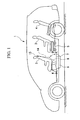
- FIG. 1 shows a two-box style vehicle 1 to which an underfloor storage structure for a vehicle in an embodiment of the present invention is applied, and which comprises three rows of seats disposed one behind another.
- the vehicle 1 has a seat arrangement in which first row seats 2, second row seats 3, and a third row seats 4 are arranged one behind another on a floor from the foreside to the backside of the vehicle 1, and each of the rows comprises two seats that are disposed laterally and separately.
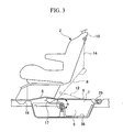
- the floor panel 5 is expanded downward at a portion thereof under the first row seats 2, and thus a storage space 6 is formed.
- a first lid 8 which opens or closes rear portion of the upper port 7, is provided so that passengers seated in the second row seats 3 can take out goods stored in the storage space 6.
- the spaces between two seats of seats 2, 3, and 4 are uses as aisles 9 through which passengers can walk laterally and longitudinally.
- the first lid 8 is disposed between the first row seats 2, and front edge thereof is connected to the floor panel 5 using hinge brackets 10 in a pivotable manner.
- the front edge of the first lid 8 is formed in a straight shape so as to extend in the lateral direction of the vehicle 1.
- the rear edge of the first lid 8 is positioned at a place slightly forward from the front end of the seat cushions of the second row seats 3, and both sides of the rear edge are formed in a rounded shape so as to prevent interference with the legs of passengers seated in the second row seats 3 during an opening or closing operation of the first lid 8.
- an opening 11 is formed at a portion thereof between the first row seats 2, in which a second lid 12 is provided that is connected to the first lid 8 using a hinge bracket 13 in a pivotable manner so as to make the front edge of the second lid 12 liftable, and so that passengers seated in the first row seats 2 can take out goods stored in the storage space 6.
- an end of a wire 14 is connected to the underside of the first lid 8, and the other end of the wire 14 is provided with a hook 15 which is, on one hand, engageable with the underside of the first lid 8 (such a configuration of the first lid 8 is not shown), and which is, on the other hand, engageable with the seatback of the first row seat 2 so that the first lid 8 is supported by the seatback of the first row seat 2 when the first lid 8 is in an open state.
- the storage space 6 is formed across the rear cross member 17, and the front edge of the first lid 8 is disposed behind the rear cross member 17. Accordingly, the front portion of the storage space 6 is covered by the floor panel 5 under which the cross member 17 is provided, and the rear portion of the storage space 6 is selectively opened or closed by the first lid 8.
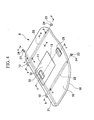
- the first lid 8 which has a multi-resin-plate structure, comprises a resin base 18, a resin mat 19 provided on the resin base 18, and metal frames 21 and 22,which will be explained below, provided inside a closed-sectional hollow body 20 made of resin (not shown in FIG. 4 ).
- the second lid 12 which has a multi-resin-plate structure, comprises a resin base 18' and a resin mat 19' provided on the resin base 18'.
- the resin base 18' is provided with a closed-sectional hollow body (not shown) on the underside peripheral portion thereof, which is formed so as to be supported by another closed-sectional hollow body (not shown) provided along the inside perimeter of the opening 11 in the first lid 8.
- first and second lids 8 and 12 are provided in the floor panel 5, the first and second lids 8 and 12 are formed so as to have rigidity and strength sufficient to support the weight of a passenger walking through the aisles 9.
- a first metal frame 21 having a hollow rectangular cross-section is provided in the first lid 8 along the lateral direction thereof, and two second metal frames 22, each of which has a hollow rectangular cross-section, are provided in the first lid 8 along the longitudinal direction thereof and substantially in parallel to the side edges of the second lid 12.
- each of the second metal frames 22 is disposed in the closed-sectional hollow body 20 that is formed on the underside of the resin base 18 disposed under the resin mat 19 so as to extend in the longitudinal direction and substantially in parallel to the side edge of the second lid 12.
- Each of the second metal frames 22 is inserted into a boss 23 of a support bracket 23, which is fixed to the resin base 18 using a screw (not shown), so as to be fixed to the resin base 18.
- the closed-sectional hollow body 20 is formed on the underside of the resin base 18 and at the front edge thereof so as to extend in the lateral direction.
- the first metal frame 21 is disposed in the closed-sectional hollow body 20 and under the second metal frame 22.
- the first metal frame 21 is, as in the case of the second metal frames 22, inserted into a boss 27 of a support bracket 26, which is fixed to the resin base 18 at the right end of the resin base 18 using a screw 25, so as to be fixed to the resin base 18.
- the hinge bracket 10 is fixed to the end face of the resin base 18 at the front end of the first lid 8 using a screw 28.
- Metal frames may also be provided to the second lid 12.
- a first handle portion 29 is provided at the rear end of the first lid 8 in a pivotable manner, and a second handle portion 30, which has a structure similar to that of the handle portion 29, is provided at the liftable end of the second lid 12.
- the levels of the first and second handle portions 29 and 30 are set to be lower than the surface of the floor panel 5 so as not to interfere with the flatness of the floor panel 5.
- the first and second handle portions 29 and 30 are configured to be returnable by springs 29a and 30a, respectively.
- the first handle portion 29 is provided for engaging a lock portion 32 with a striker 31 provided to the floor panel 5, and the second handle portion 30 is provided for engaging a lock portion 32 with a striker 31 provided to the opening 11 of the first lid 8.
- the hinge bracket 13 is disposed between the second lid 12 and the opening 11 of the first lid 8, while an end thereof is fixed to the base of the second lid 12 using a screw 33, and the other end thereof is fixed to the base of the first lid 8 using another screw 33.
- FIGS. 5 and 6 show cross-sections around the hinge bracket 13, and more specifically, FIG. 5 shows a cross-section taken along the screw 28 of the hinge bracket 10, and FIG. 6 shows a cross-section taken along the second metal frame 22.
- a tray unit 34 In the storage space 6 formed under the first lid 8 in a manner as described above, there is provided a tray unit 34.
- the tray unit 34 comprises a tray body 35 which is made of resin, and which is formed in a shape corresponding to that of the floor panel 5 being concave downward, and a rotatable tray 36 which is made of resin, and which is made rotatable in such a manner that the surface thereof moves along the concave surface of the floor panel 5.
- the tray body 35 comprises a flat bottom wall (bottom portion) 35a, and a peripheral wall 35b extending from the periphery of the bottom wall 35a in an inclined manner (as viewed in a cross-section). There are provided insulation materials 37 between the bottom wall 35a and the floor panel 5, and between the peripheral wall 35b and the floor panel 5 that forms the storage space 6.
- a support base 38 for rotatably supporting the rotatable tray 36.
- the support base 38 comprises a support element 39 made of metal, a backing plate 40 made of metal, and a portion of the tray body 35 made of resin (more specifically, a portion of the bottom wall 35a) sandwiched between the support element 39 and the backing plate 40.
- the support element 39 is a cup-shaped element made by press-forming a metal plate, and the support element 39 is attached to the bottom wall 35a of the tray body 35 in such a manner that an opening of the support element 39 is directed downward.
- a flange 41 is formed around the opening of the support element 39, and the backing plate 40 made of metal is provided on the underside of the bottom wall 35a of the tray body 35 so as to positionally correspond to the flange 41.
- the backing plate 40 is connected to the flange 41 using rivets 42 so as to act as reinforcement. More specifically, the bottom wall 35a of the tray body 35 is sandwiched between the flange 41 of the support element 39 and the backing plate 40, whereby supporting rigidity of the support element 39 is increased.
- a pipe-shaped shaft 43 is welded to an upper wall 39a of the support element 39.
- the rotatable tray 36 is rotatably supported by means of a bearing 44 provided to the shaft 43.
- the rotatable tray 36 in this embodiment comprises the bottom wall 36a having a circular shape corresponding to the tray body 35, and the peripheral wall 36b.
- the rotatable tray 36 further comprises, at the center thereof, a mounting portion 46 which includes a shoulder portion 45, and which is raised from the bottom wall 36a so as to clear the support element 39 and the shaft 43.
- An attachment portion 47 having a concave shape is formed inside the shoulder portion 45 of the mounting portion 46 for installation of the bearing 44.
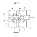
- the rotatable tray 36 further comprises three partition walls 48 which extend from the mounting portion 46 to the peripheral wall 36b are provided at every 120 degrees so as to form three separate storage sections 49 in the rotatable tray 36. The number of separate storage sections may be three or more.
- each of the separate storage sections 49 is formed such that most portion thereof is exposed when the second lid 12 is opened (see FIG. 2 ).
- Each of the partition walls 48 is formed as a hollow rib extending from the bottom wall 36a so as to have sufficient rigidity.
- ribs 50 are formed in the partition wall 48, which downwardly extends from the top wall of the partition wall 48 as shown in FIG. 11 .
- each of the partition walls 48 is provided with a wheel 51 at the bottom thereof, which rolls along a circumferential direction of the tray body 35 while contacting the bottom wall 35a of the tray body 35, and with which the rotatable tray 36 rotatable about the support element 39 of the tray body 35 is supported by the tray body 35.
- a relief portion 52 is formed on the partition wall 48 in the vicinity of the wheel 51 in order to prevent interference between the partition wall 48 and the wheel 51.
- a separating wall 53 is attached to a front half of the upper periphery of the tray body 35 so as to cover a forward portion of the rotatable tray 36 with respect to the mounting portion 46, and so as to separate floor panel 5 disposed under the first row seats 2 from the rotatable tray 36, whereby a piece of luggage is prevented from interfering with the floor panel 5, and as a result, the rotatable tray 36 may be smoothly rotated, and pieces of luggage may be smoothly handled.
- a cushion 65 extending in the lateral direction of the vehicle 1 in order to prevent noise due to interference of the separating wall 53 with the cross member 17 disposed under the floor panel 5.
- a locking element 54 (part of a locking mechanism) is provided in such a manner that a portion of the locking element 54 is inserted into the hollow shaft 43, and the locking element 54 is made movable vertically while being biased upward by a spring 55(part of a locking mechanism).
- Through holes 43a are formed in an upper portion of the shaft 43 so as to penetrate the shaft 43 in the diametrical direction thereof.
- a locking pin 57 is inserted into the through holes 43a, and is fixed thereto using an E-ring 58.
- the locking element 54 comprises a flange portion 54a, a shaft portion 54b, and a through hole 56 formed in the center of the shaft portion 54b.
- engagement teeth G1 part of a locking mechanism
- the engagement teeth G1 are made engageable with corresponding engagement teeth G2 (part of a locking mechanism) which are formed on the upper surface of the shoulder portion 45 of the mounting portion 46 of the rotatable tray 36. Accordingly, the rotation of the rotatable tray 36 can be locked at every possible engaging state between the engagement teeth G1 and the engagement teeth G2.
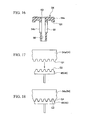
- the gear tooth shape defining the engagement teeth G1 and G2 may be a trapezoidal shape as shown in FIGS. 17 and 18 , or alternatively, the shape may be a curved shape such as a sinusoidal shape, and the shape may be preferably determined such that rotation of the rotatable tray 36 in an engaging state produces an axial movement of the locking element 54 as will be explained below.
- elongated through holes 59 elongated in the vertical direction are formed in the shaft portion 54b so as to penetrate the shaft portion 54b in the diametrical direction thereof.
- the locking pin 57 fixed to the shaft 43 is disposed through the elongated through holes 59 so that vertical movement of the locking element 54 is restrained, and coming off of the locking element 54 is prevented.
- the diameter of a lower portion of the shaft portion 54b as viewed from the elongated through holes 59 is made smaller than that of a portion where the elongated through holes 59 are formed so that the spring 55 is mounted thereto. Furthermore, a step portion 60 is formed around an opening of the through hole 56 of the flange portion 54a.
- a hole 39b which has the same inner diameter as that of the through hole 56 of the locking element 54, is formed in the upper wall 39a of the support element 39 and in the center of the attachment region for the shaft 43, and a push rod 61 (a part of a locking mechanism) is disposed through the hole 39b and the through hole 56 of the locking element 54 so be movable in the vertical direction.
- the push rod 61 comprises an enlarged diameter portion 61a disposed at the bottom thereof, and an elongated through hole 61b formed in the middle thereof through which the locking pin 57 is disposed.
- the push rod 61 is provided, at the top thereof, with a push knob 63 (a part of a locking mechanism) fixed thereto using a screw 62.
- the push knob 63 comprises a head portion 63a and a shaft portion 63b.
- a push spring 64 (a part of a locking mechanism) is disposed between the underside of the head portion 63a and the step portion 60 formed in the flange portion 54a of the locking element 54 so as to press the locking element 54 downward.
- An insertion hole 63c for the screw 62 is formed in the center of the shaft portion 63b so as to allow the screw 62 to be fixed to the upper end of the push rod 61.
- a clearance L (see FIG. 19 ) sufficient to cancel the engagement between the engagement teeth G1 of the locking element 54 and the engagement teeth G2 on the shoulder portion 45 of the rotatable tray 36 when the first lid 8 is in a closed state.
- the dimensions of the push rod 61 in the axial direction thereof are determined such that the engagement between the engagement teeth G1 of the locking element 54 and the engagement teeth G2 on the shoulder portion 45 of the rotatable tray 36 is not inhibited by the push rod 61 when both of the first and second lids 8 and 12 are closed, and whereby the push knob 63 is pressed downward.
- the under side of the handle portion 30 of the second lid 12 is provided with a plane P that presses the push knob 63 downward when the second lid 12 is closed; therefore, when both of the first and second lids 8 and 12 are closed, the plane P presses the push knob 63 downward so as to place the engagement teeth G1 and the engagement teeth G2 in a locking state in which the engagement teeth G1 and G2 engage with respect to each other (see FIG. 19 ), while on the other hand, when either the first lid 8 or the second lid 12 is opened, because the plane P of the second lid 12 moves upward so as to cancel the pressed state of the push knob 63, the locking state between the engagement teeth G1 and G2 is cancelled (see FIG. 21 ).
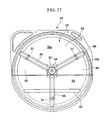
- the arrow in FIG. 17 indicates downward movement of the engagement teeth G1 (i.e., downward movement of the locking element 54) when both of the first and second lids 8 and 12 are in a process of being closed.
- the spring constant of the spring 55 is determined such that the spring 55 is compressed due to the weight of the first lid 8 so as place the engagement teeth G1 and the engagement teeth G2 in a locking state (see FIG. 18 ) when the first lid 8 is closed as shown in FIGS. 19 and 20 .
- the push spring 64 is provided to prevent the engagement teeth G1 and G2 from being broken even when a large rotational force is applied to the rotatable tray 36 due to such as inertia of the luggage in a state in which the first lid 8 is closed, and the engagement teeth G1 and the engagement teeth G2 are placed in a locking state.
- the push spring 64 also acts to allow dimensional variations in the plane P and the upper portion of the head portion 63a of the push knob 63.
- the spring constant of the push spring 64 is determined such that the clearance L between the locking element 54 and the push knob 63 is ensured even when the first lid 8 is closed and the push knob 63 is pressed downward so as to compress the spring 55.
- one of the separate storage sections 49 disposed at the distal position may be moved to the proximal position by opening the first lid 8 and by rotating the rotatable tray 36, a piece of luggage stored in the rotatable tray 36 of the storage space 6, specifically in a portion thereof covered by the floor panel 5 (in a distal portion thereof), may be taken out after being moved to the proximal position.
- a piece of luggage placed in one of the separate storage sections 49 of the rotatable tray 36, which is disposed at the proximal position may be moved to the distal position for storing by rotating the rotatable tray 36. Accordingly, a piece of luggage stored in any one of the separate storage sections 49, which may be of small size, can be easily taken out, and the piece of luggage can be stored at any position in the storage space 6.
- first lid 8 when the first lid 8 is opened, approximately a half of the storage space 6 is exposed, and a piece of luggage may be taken out, if necessary, by rotating the rotatable tray 36 in an unlocked state until the piece of luggage stored in the rotatable tray 36 appears.
- second lid 12 when the second lid 12 is opened, a piece of luggage may be taken out, if necessary, by rotating the rotatable tray 36 in an unlocked state until the piece of luggage appears in the opening 11 formed in the first lid 8.
- the first and second lids 8 and 12 allow passengers to access pieces of luggage stored in the storage space 6, i.e., either a passenger seated in the first row seat 2 or a passenger seated in the second row seat 3 can freely and easily access pieces of luggage stored in the storage space 6 even when access is frequently made.
- the rotatable tray 36 is provided in the storage space 6, and three separate storage sections 49 are formed in the rotatable tray 36, it is possible to place and store pieces of luggage in each of the separate storage sections 49 while opening the second lid 12 and rotating the rotatable tray 36, or it is possible to place and store pieces of luggage in one of the separate storage sections 49, which enables an easy access thereto after storing, while opening the first lid 8, and thus the entirety of the storage space 6 can be effectively utilized.
- the rotatable tray 36 is divided into three separate storage sections 49 by the partition walls 48, and the rotatable tray 36 is configured to be locked by closing the first lid 8 or the second lid 12, when a force, which could produce rotation of the rotatable tray 36, is applied to the partition walls 48, the rotation of the rotatable tray 36 is restrained by the engagement between the engagement teeth G1 and G2 in a state in which the first lid 8 or the second lid 12 is closed. Accordingly, the positions of pieces of luggage stored in the rotatable tray 36 will not be changed due to traveling of the vehicle 1, and thus the positions of pieces of luggage can be remembered. In addition, noise due to rotation or vibration of the rotatable tray 36 can be prevented.
- the rotatable tray 36 is not broken even when a relatively heavy package (e.g., a bag of rice or the like) is stored in the rotatable tray 36, and a large load is applied to the rotatable tray 36 due to a braking operation of the vehicle.
- a relatively heavy package e.g., a bag of rice or the like
- the first lid 8 comprises the metal frames 21 and 22, and a multi-resin-plate structure primarily including the mat 19 and the resin base 18, and the second lid 12 also comprises a multi-resin-plate structure primarily including the mat 19' and the resin base 18', the rigidities and strengths of the first and second lids 8 and 12 can be sufficiently ensured when the first and second lids 8 and 12 are closed so as to be flat with the floor panel 5.
- the flange 41 of the support base 38 (support element 39) for rotatably supporting the rotatable tray 36 is fixed such that the bottom wall 35a of the resin tray body 35 is sandwiched between the flange 41 and metal backing plate 40, the supporting rigidity of the rotatable tray 36 can be sufficiently ensured. Accordingly, the storage space 6 can be disposed under the aisles 9 without any problems.
- the storage space 6 is provided under the floor panel 5 under the first row seats 2, and the separating wall 53 is provided between the floor panel 5 under the first row seats 2 and the rotatable tray 36; therefore, a piece of luggage will not be engaged between the rotatable tray 36 and the floor panel 5 so as to inhibit rotation of the rotatable tray 36, and as a result, pieces of luggage may be smoothly taken out from the rotatable tray 36 or placed in the rotatable tray 36.
- the present invention is not limited to the above-explained embodiment.
- the locking mechanism is not limited to the above configuration, and any configuration may be employed as long as the rotation of the rotatable tray 36 can be restrained.
- the present invention is applicable to a vehicle in which the number of rows of seats is not three, i.e., the present invention is applicable to a vehicle having two rows of seats or four rows of seats.
- one of the separate storage sections disposed at the distal position may be moved to the proximal position by opening the lid and by rotating the rotatable tray, a piece of luggage stored in a portion of the storage space that is covered by the floor panel (in a distal portion thereof) may be taken out after being moved to the proximal position.
- a piece of luggage placed in one of the separate storage sections that is disposed at the proximal position may be moved to the distal position for storing by rotating the rotatable tray. Accordingly, a piece of luggage stored in any one of the separate storage sections, which may be of small size, can be easily taken out, and a piece of luggage can be stored at any position in the storage space.
- a passenger seated in a first row seat can take out a piece of luggage by opening the second lid even when passengers seated in a second seat put their legs on the first lid, and a passenger seated in the second row seat can take out a piece of luggage by opening the first lid, passengers can freely and easily access pieces of luggage stored in the storage space even when access is frequently made.
- the rotation of the rotatable tray is restrained by the locking mechanism in a state in which the lid is closed; therefore, noise due to rotation or vibration of the rotatable tray can be preferably prevented. Furthermore, the pieces of luggage in the storage space will not be broken due to excessive circumferential movement thereof.
- the rotatable tray and the locking mechanism are prevented from being broken. Therefore, the rotatable tray is not broken even when a relatively heavy package is stored in the rotatable tray, and a large load is applied to the rotatable tray due to a braking operation of the vehicle. Moreover, variation in relative positioning between the lid and the rotatable tray may be reduced.
- the lid may be disposed in the aisles that may support the weight of the passengers.
- the storage space may be disposed under the aisles that may support the weight of the passengers.
- pieces of luggage may be smoothly taken out from the rotatable tray or placed in the rotatable tray.
Abstract
Description
- The present invention relates to an underfloor storage structure for a vehicle, and in particular, the present invention relates to an underfloor storage structure for a vehicle, which is provided therein with a rotatable tray.
- As disclosed, for example, in Japanese Unexamined Patent Application, First Publication No.
Hei 11-105746 - According to such an underfloor storage structure, because the lid for opening or closing the port of the storage space is disposed between the front seats and the rear seats, an advantage is obtained in that access to the inside of the storage space may be made without tilting the seats.
- When the above-mentioned underfloor storage space is employed for goods such as a spare tire, which are relatively large, and which are not frequently used, any problems are encountered; however, when the underfloor storage space is employed for small goods such as other than a spare tire, a problem is encountered in that it is difficult the floor panel. More specifically, when small goods are stored in a large space, which is large so as to accommodate a spare tire, the small goods must be found in the large space before being accessed to and being taken out, which is time-consuming.
- A storage system according to the preamble of
claim 1 is disclosed inUS-B1-6 338 518 . The storage system is accessible by opening the tailgate of a vehicle, and is provided with a load floor. The load floor functions as a lid to cover a lazy susan, mounted in a storage space of a floor panel beneath the load floor. - A motor vehicle seat with an incorporated storage drawer, positioned underneath the vehicle seat, is disclosed in
FR-A-2 710 297 - In consideration of the above circumstances, an object of the present invention is to provide an underfloor storage structure for a vehicle, which enables a person to easily and smoothly take out small goods, in which a number of small goods may be stored, the small goods may be taken out from various directions, and stored goods will not move around when the vehicle travels, and which has sufficient rigidity and strength so that structural elements thereof will not be broken even when heavy goods are stored therein.
- In order to achieve the above object, the present invention provides an underfloor storage structure for a vehicle according to
claim 1. - According to the above underfloor storage structure of the present invention, because one of the separate storage sections disposed at the distal position may be moved to the proximal position by opening the lid and by rotating the rotatable tray, a piece of luggage stored in a portion of the storage space that is covered by the floor panel may be taken out after being moved to the proximal position. On the other hand, a piece of luggage placed in one of the separate storage sections that is disposed at the proximal position may be moved to the distal position for storing by rotating the rotatable tray, and thus many pieces of luggage may be stored therein.
- According to the above underfloor storage structure, the passengers can freely and easily access pieces of luggage stored in the storage space. More specifically, a passenger seated in the first row seat can take out a piece of luggage by opening the second lid even when passengers seated in the second seat put their legs on the first lid, and a passenger seated in the second row seat can take out a piece of luggage by opening the first lid. In addition, a piece of luggage stored in a portion of the storage space under the first seats may be taken out after rotating the rotatable tray. The second lid may be located between the separate first row seats.
- In the above underfloor storage structure, the rotatable tray may comprise partition walls therein, and a locking mechanism may be provided for the rotatable tray, which locks the rotation of the rotatable tray upon closing the first or second lid.
- According to the above underfloor storage structure, a plurality of separate storage sections can be ensured in the rotatable tray by dividing the inside of the rotatable tray. Moreover, when a force, which could produce rotation of the rotatable tray, is applied to the partition walls, the rotation of the rotatable tray is restrained by the locking mechanism in a state in which the first lid and second lids are closed. In addition, the pieces of luggage in the storage space will not be broken due to excessive circumferential movement thereof.
- In the above underfloor storage structure, the locking mechanism may be greater than a predetermined value due to luggage stored in the rotatable tray is applied to the rotatable tray.
- According to the above underfloor storage structure, because the locking state of the locking mechanism is temporarily cancelled when an excessive rotational force is applied to the partition walls due to the stored luggage, the rotatable tray and the locking mechanism are prevented from being broken.
- In the above underfloor storage structure, the lid may comprise a metal frame and a resin plate.
- According to the above underfloor storage structure, the rigidity and strength of the lid can be sufficiently ensured when the lid is closed so as to be flat with the floor panel.
- In the above underfloor storage structure, on the bottom of the storage space, there may be provided a support base for rotatably supporting the rotatable tray, and the support base may comprise a support element made of metal, a backing plate made of metal, and a resin tray body sandwiched between the support element and the backing plate.
- According to the above underfloor storage structure, the supporting rigidity of the rotatable tray can be sufficiently ensured.
- In the above underfloor storage structure, a separating wall is provided between the floor panel under the first row seats and the rotatable tray.
- According to the above underfloor storage structure, a piece of luggage will not be engaged between the rotatable tray and the floor panel, and as a result, the rotation of the rotatable tray will not be inhibited.
-
-
FIG. 1 is a perspective side view showing a vehicle of an embodiment of the present invention. -
FIG. 2 is a plan view showing a floor of the vehicle of the present invention. -
FIG. 3 is an enlarged view showing a major portion inFIG. 1 . -
FIG. 4 is a perspective view showing a first lid in the embodiment of the present invention. -
FIG. 5 is a cross-sectional view taken along the line a-a inFIG. 4 . -
FIG. 6 is a cross-sectional view taken along the line b-b inFIG. 4 . -
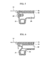
FIG. 7 is a cross-sectional view taken along the line c-c inFIG. 4 . -
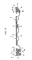
FIG. 8 is a cross-sectional view taken along the line d-d inFIG. 4 . -
FIG. 9 is a cross-sectional view taken along the line e-e inFIG. 4 . -
FIG. 10 is a cross-sectional view taken along the line f-f inFIG. 4 . -
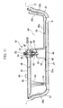
FIG. 11 is a cross-sectional view taken along the line g-g inFIG. 1 . -
FIG. 12 is a plan view showing a tray unit in the embodiment of the present invention. -
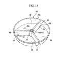
FIG. 13 is a perspective view showing a rotatable tray in the embodiment of the present invention. -
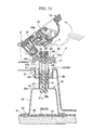
FIG. 14 is an enlarged cross-sectional view showing the portion "h" inFIG. 1 . -
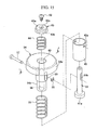
FIG. 15 is an exploded perspective view showing a locking unit. -
FIG. 16 is a cross-sectional view taken along the line i-i inFIG. 15 . -
FIG. 17 is a side view as viewed from the arrow "j" inFIG. 14 . -
FIG. 18 is a side view as viewed from the arrow "k" inFIG. 19 . -
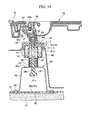
FIG. 19 is a cross-sectional view showing a handle portion of a second lid in a state in which the first lid is closed. -
FIG. 20 is a cross-sectional view showing a handle portion of the first lid in a state in which the first lid is closed. -
FIG. 21 is a cross-sectional view, corresponding toFIG. 19 , showing the handle portion of the second lid in a state in which the first lid or the second lid is opened. - An embodiment of the present invention will be explained below with reference to the appended drawings.
-
FIG. 1 shows a two-box style vehicle 1 to which an underfloor storage structure for a vehicle in an embodiment of the present invention is applied, and which comprises three rows of seats disposed one behind another. - The
vehicle 1 has a seat arrangement in whichfirst row seats 2,second row seats 3, and athird row seats 4 are arranged one behind another on a floor from the foreside to the backside of thevehicle 1, and each of the rows comprises two seats that are disposed laterally and separately. - The
floor panel 5 is expanded downward at a portion thereof under thefirst row seats 2, and thus astorage space 6 is formed. To anupper port 7 of thestorage space 6, afirst lid 8, which opens or closes rear portion of theupper port 7, is provided so that passengers seated in thesecond row seats 3 can take out goods stored in thestorage space 6. - As shown in
FIGS. 2 and3 , the spaces between two seats ofseats aisles 9 through which passengers can walk laterally and longitudinally. Thefirst lid 8 is disposed between thefirst row seats 2, and front edge thereof is connected to thefloor panel 5 usinghinge brackets 10 in a pivotable manner. - The front edge of the
first lid 8 is formed in a straight shape so as to extend in the lateral direction of thevehicle 1. The rear edge of thefirst lid 8 is positioned at a place slightly forward from the front end of the seat cushions of thesecond row seats 3, and both sides of the rear edge are formed in a rounded shape so as to prevent interference with the legs of passengers seated in thesecond row seats 3 during an opening or closing operation of thefirst lid 8. - In the
first lid 8, anopening 11 is formed at a portion thereof between thefirst row seats 2, in which asecond lid 12 is provided that is connected to thefirst lid 8 using ahinge bracket 13 in a pivotable manner so as to make the front edge of thesecond lid 12 liftable, and so that passengers seated in thefirst row seats 2 can take out goods stored in thestorage space 6. - In addition, as shown in
FIGS. 1 and3 , an end of awire 14 is connected to the underside of thefirst lid 8, and the other end of thewire 14 is provided with ahook 15 which is, on one hand, engageable with the underside of the first lid 8 (such a configuration of thefirst lid 8 is not shown), and which is, on the other hand, engageable with the seatback of thefirst row seat 2 so that thefirst lid 8 is supported by the seatback of thefirst row seat 2 when thefirst lid 8 is in an open state. - As shown in
FIG. 3 , under two portions of thefloor panel 5 corresponding to the front end and rear end of thefirst row seats 2, there are provided afront cross member 16 andrear cross member 17, respectively, each of which extends in the lateral direction of thevehicle 1. Thestorage space 6 is formed across therear cross member 17, and the front edge of thefirst lid 8 is disposed behind therear cross member 17. Accordingly, the front portion of thestorage space 6 is covered by thefloor panel 5 under which thecross member 17 is provided, and the rear portion of thestorage space 6 is selectively opened or closed by thefirst lid 8. - As shown in
FIGS. 4 to 9 , thefirst lid 8, which has a multi-resin-plate structure, comprises aresin base 18, aresin mat 19 provided on theresin base 18, andmetal frames hollow body 20 made of resin (not shown inFIG. 4 ). - As shown in
FIG. 10 , thesecond lid 12, which has a multi-resin-plate structure, comprises a resin base 18' and a resin mat 19' provided on the resin base 18'. The resin base 18' is provided with a closed-sectional hollow body (not shown) on the underside peripheral portion thereof, which is formed so as to be supported by another closed-sectional hollow body (not shown) provided along the inside perimeter of theopening 11 in thefirst lid 8. - Because the first and
second lids floor panel 5, the first andsecond lids aisles 9. - More specifically, with reference to
FIG. 4 , afirst metal frame 21 having a hollow rectangular cross-section is provided in thefirst lid 8 along the lateral direction thereof, and two second metal frames 22, each of which has a hollow rectangular cross-section, are provided in thefirst lid 8 along the longitudinal direction thereof and substantially in parallel to the side edges of thesecond lid 12. - As shown in
FIGS. 8 and9 , each of the second metal frames 22 is disposed in the closed-sectionalhollow body 20 that is formed on the underside of theresin base 18 disposed under theresin mat 19 so as to extend in the longitudinal direction and substantially in parallel to the side edge of thesecond lid 12. Each of the second metal frames 22 is inserted into aboss 23 of asupport bracket 23, which is fixed to theresin base 18 using a screw (not shown), so as to be fixed to theresin base 18. - As shown in
FIGS. 5 to 7 , the closed-sectionalhollow body 20 is formed on the underside of theresin base 18 and at the front edge thereof so as to extend in the lateral direction. Thefirst metal frame 21 is disposed in the closed-sectionalhollow body 20 and under thesecond metal frame 22. As shown inFIG. 7 , thefirst metal frame 21 is, as in the case of the second metal frames 22, inserted into aboss 27 of asupport bracket 26, which is fixed to theresin base 18 at the right end of theresin base 18 using ascrew 25, so as to be fixed to theresin base 18. As shown inFIGS. 5 and 6 , thehinge bracket 10 is fixed to the end face of theresin base 18 at the front end of thefirst lid 8 using ascrew 28. Metal frames may also be provided to thesecond lid 12. - As shown in
FIG. 10 , afirst handle portion 29 is provided at the rear end of thefirst lid 8 in a pivotable manner, and asecond handle portion 30, which has a structure similar to that of thehandle portion 29, is provided at the liftable end of thesecond lid 12. The levels of the first andsecond handle portions floor panel 5 so as not to interfere with the flatness of thefloor panel 5. The first andsecond handle portions springs - The
first handle portion 29 is provided for engaging alock portion 32 with astriker 31 provided to thefloor panel 5, and thesecond handle portion 30 is provided for engaging alock portion 32 with astriker 31 provided to theopening 11 of thefirst lid 8. Thehinge bracket 13 is disposed between thesecond lid 12 and theopening 11 of thefirst lid 8, while an end thereof is fixed to the base of thesecond lid 12 using ascrew 33, and the other end thereof is fixed to the base of thefirst lid 8 using anotherscrew 33. - Accordingly, when the
first handle portion 29 is pivoted while overcoming the restoring force of thespring 29a, thelock portion 32 pressed against thefirst handle portion 29 is moved while overcoming the restoring force of aspring 32a so that thelock portion 32 is disengaged from the correspondingstriker 31, and as a result, thefirst lid 8 can be opened by lifting up thefirst handle portion 29. On the other hand, when thesecond handle portion 30 is pivoted while overcoming the restoring force of thespring 30a, thelock portion 32 pressed against thesecond handle portion 30 is moved while overcoming the restoring force of aspring 32a so that thelock portion 32 is disengaged from the correspondingstriker 31, and as a result, thesecond lid 12 can be opened by lifting up thesecond handle portion 29.FIGS. 5 and 6 show cross-sections around thehinge bracket 13, and more specifically,FIG. 5 shows a cross-section taken along thescrew 28 of thehinge bracket 10, andFIG. 6 shows a cross-section taken along thesecond metal frame 22. - In the
storage space 6 formed under thefirst lid 8 in a manner as described above, there is provided atray unit 34. - The
tray unit 34 comprises atray body 35 which is made of resin, and which is formed in a shape corresponding to that of thefloor panel 5 being concave downward, and arotatable tray 36 which is made of resin, and which is made rotatable in such a manner that the surface thereof moves along the concave surface of thefloor panel 5. - The
tray body 35 comprises a flat bottom wall (bottom portion) 35a, and aperipheral wall 35b extending from the periphery of thebottom wall 35a in an inclined manner (as viewed in a cross-section). There are providedinsulation materials 37 between thebottom wall 35a and thefloor panel 5, and between theperipheral wall 35b and thefloor panel 5 that forms thestorage space 6. - At the center of the
bottom wall 35a, which is substantially the bottom portion of thestorage space 6, of thetray body 35, there is provided asupport base 38 for rotatably supporting therotatable tray 36. Thesupport base 38 comprises asupport element 39 made of metal, abacking plate 40 made of metal, and a portion of thetray body 35 made of resin (more specifically, a portion of thebottom wall 35a) sandwiched between thesupport element 39 and thebacking plate 40. - The
support element 39 is a cup-shaped element made by press-forming a metal plate, and thesupport element 39 is attached to thebottom wall 35a of thetray body 35 in such a manner that an opening of thesupport element 39 is directed downward. Aflange 41 is formed around the opening of thesupport element 39, and thebacking plate 40 made of metal is provided on the underside of thebottom wall 35a of thetray body 35 so as to positionally correspond to theflange 41. Thebacking plate 40 is connected to theflange 41 usingrivets 42 so as to act as reinforcement. More specifically, thebottom wall 35a of thetray body 35 is sandwiched between theflange 41 of thesupport element 39 and thebacking plate 40, whereby supporting rigidity of thesupport element 39 is increased. - A pipe-shaped
shaft 43 is welded to anupper wall 39a of thesupport element 39. Therotatable tray 36 is rotatably supported by means of abearing 44 provided to theshaft 43. - As shown in
FIG. 13 , therotatable tray 36 in this embodiment comprises thebottom wall 36a having a circular shape corresponding to thetray body 35, and theperipheral wall 36b. Therotatable tray 36 further comprises, at the center thereof, a mountingportion 46 which includes ashoulder portion 45, and which is raised from thebottom wall 36a so as to clear thesupport element 39 and theshaft 43. Anattachment portion 47 having a concave shape is formed inside theshoulder portion 45 of the mountingportion 46 for installation of thebearing 44. Therotatable tray 36 further comprises threepartition walls 48 which extend from the mountingportion 46 to theperipheral wall 36b are provided at every 120 degrees so as to form threeseparate storage sections 49 in therotatable tray 36. The number of separate storage sections may be three or more. Since therotatable tray 36 is configured in such a manner, pieces of luggage may be stored in theseparate storage sections 49 in an orderly manner. Each of theseparate storage sections 49 is formed such that most portion thereof is exposed when thesecond lid 12 is opened (seeFIG. 2 ). - Each of the
partition walls 48 is formed as a hollow rib extending from thebottom wall 36a so as to have sufficient rigidity. In order to further increase rigidity of thepartition wall 48,ribs 50 are formed in thepartition wall 48, which downwardly extends from the top wall of thepartition wall 48 as shown inFIG. 11 . - Moreover, as shown in
FIG. 11 , each of thepartition walls 48 is provided with awheel 51 at the bottom thereof, which rolls along a circumferential direction of thetray body 35 while contacting thebottom wall 35a of thetray body 35, and with which therotatable tray 36 rotatable about thesupport element 39 of thetray body 35 is supported by thetray body 35. Arelief portion 52 is formed on thepartition wall 48 in the vicinity of thewheel 51 in order to prevent interference between thepartition wall 48 and thewheel 51. - As shown in
FIGS. 11 and12 , a separatingwall 53 is attached to a front half of the upper periphery of thetray body 35 so as to cover a forward portion of therotatable tray 36 with respect to the mountingportion 46, and so as to separatefloor panel 5 disposed under thefirst row seats 2 from therotatable tray 36, whereby a piece of luggage is prevented from interfering with thefloor panel 5, and as a result, therotatable tray 36 may be smoothly rotated, and pieces of luggage may be smoothly handled. - On the upper face of the separating
wall 53, there is provided acushion 65 extending in the lateral direction of thevehicle 1 in order to prevent noise due to interference of the separatingwall 53 with thecross member 17 disposed under thefloor panel 5. - Furthermore, as shown in
FIGS. 14 to 16 , a locking element 54 (part of a locking mechanism) is provided in such a manner that a portion of the lockingelement 54 is inserted into thehollow shaft 43, and the lockingelement 54 is made movable vertically while being biased upward by a spring 55(part of a locking mechanism). - Through
holes 43a are formed in an upper portion of theshaft 43 so as to penetrate theshaft 43 in the diametrical direction thereof. A lockingpin 57 is inserted into the throughholes 43a, and is fixed thereto using an E-ring 58. - As shown in
FIG. 15 , the lockingelement 54 comprises aflange portion 54a, ashaft portion 54b, and a throughhole 56 formed in the center of theshaft portion 54b. Moreover, as shown inFIGS. 17 and 18 , there are formed engagement teeth G1 (part of a locking mechanism) each having a gear tooth shape on the underside and the periphery of the lockingelement 54. The engagement teeth G1 are made engageable with corresponding engagement teeth G2 (part of a locking mechanism) which are formed on the upper surface of theshoulder portion 45 of the mountingportion 46 of therotatable tray 36. Accordingly, the rotation of therotatable tray 36 can be locked at every possible engaging state between the engagement teeth G1 and the engagement teeth G2. Note that the gear tooth shape defining the engagement teeth G1 and G2 may be a trapezoidal shape as shown inFIGS. 17 and 18 , or alternatively, the shape may be a curved shape such as a sinusoidal shape, and the shape may be preferably determined such that rotation of therotatable tray 36 in an engaging state produces an axial movement of the lockingelement 54 as will be explained below. - In addition, elongated through
holes 59 elongated in the vertical direction are formed in theshaft portion 54b so as to penetrate theshaft portion 54b in the diametrical direction thereof. The lockingpin 57 fixed to theshaft 43 is disposed through the elongated throughholes 59 so that vertical movement of the lockingelement 54 is restrained, and coming off of the lockingelement 54 is prevented. - The diameter of a lower portion of the
shaft portion 54b as viewed from the elongated throughholes 59 is made smaller than that of a portion where the elongated throughholes 59 are formed so that thespring 55 is mounted thereto. Furthermore, astep portion 60 is formed around an opening of the throughhole 56 of theflange portion 54a. - Moreover, a
hole 39b, which has the same inner diameter as that of the throughhole 56 of the lockingelement 54, is formed in theupper wall 39a of thesupport element 39 and in the center of the attachment region for theshaft 43, and a push rod 61 (a part of a locking mechanism) is disposed through thehole 39b and the throughhole 56 of the lockingelement 54 so be movable in the vertical direction. Thepush rod 61 comprises anenlarged diameter portion 61a disposed at the bottom thereof, and an elongated throughhole 61b formed in the middle thereof through which thelocking pin 57 is disposed. Thepush rod 61 is provided, at the top thereof, with a push knob 63 (a part of a locking mechanism) fixed thereto using ascrew 62. - As shown in
FIG. 15 , thepush knob 63 comprises ahead portion 63a and ashaft portion 63b. A push spring 64 (a part of a locking mechanism) is disposed between the underside of thehead portion 63a and thestep portion 60 formed in theflange portion 54a of the lockingelement 54 so as to press the lockingelement 54 downward. Aninsertion hole 63c for thescrew 62 is formed in the center of theshaft portion 63b so as to allow thescrew 62 to be fixed to the upper end of thepush rod 61. Between the bottom end of theshaft portion 63b and the bottom of thestep portion 60 of the lockingelement 54, there is provided a clearance L (seeFIG. 19 ) sufficient to cancel the engagement between the engagement teeth G1 of the lockingelement 54 and the engagement teeth G2 on theshoulder portion 45 of therotatable tray 36 when thefirst lid 8 is in a closed state. - As shown in
FIG. 19 , the dimensions of thepush rod 61 in the axial direction thereof are determined such that the engagement between the engagement teeth G1 of the lockingelement 54 and the engagement teeth G2 on theshoulder portion 45 of therotatable tray 36 is not inhibited by thepush rod 61 when both of the first andsecond lids push knob 63 is pressed downward. - More specifically, the under side of the
handle portion 30 of thesecond lid 12 is provided with a plane P that presses thepush knob 63 downward when thesecond lid 12 is closed; therefore, when both of the first andsecond lids push knob 63 downward so as to place the engagement teeth G1 and the engagement teeth G2 in a locking state in which the engagement teeth G1 and G2 engage with respect to each other (seeFIG. 19 ), while on the other hand, when either thefirst lid 8 or thesecond lid 12 is opened, because the plane P of thesecond lid 12 moves upward so as to cancel the pressed state of thepush knob 63, the locking state between the engagement teeth G1 and G2 is cancelled (seeFIG. 21 ). Note that the arrow inFIG. 17 indicates downward movement of the engagement teeth G1 (i.e., downward movement of the locking element 54) when both of the first andsecond lids - The spring constant of the
spring 55 is determined such that thespring 55 is compressed due to the weight of thefirst lid 8 so as place the engagement teeth G1 and the engagement teeth G2 in a locking state (seeFIG. 18 ) when thefirst lid 8 is closed as shown inFIGS. 19 and20 . Thepush spring 64 is provided to prevent the engagement teeth G1 and G2 from being broken even when a large rotational force is applied to therotatable tray 36 due to such as inertia of the luggage in a state in which thefirst lid 8 is closed, and the engagement teeth G1 and the engagement teeth G2 are placed in a locking state. More specifically, when a large rotational force is applied to therotatable tray 36 in the above-mentioned state, an axial movement of the lockingelement 54 is produced, while overcoming the restoring force of thepush spring 64, by the rotation of therotatable tray 36, i.e., the engagement teeth G1 are raised by the engagement teeth G2, and a result, the locking state between the engagement teeth G1 and G2 is temporarily cancelled. Thepush spring 64 also acts to allow dimensional variations in the plane P and the upper portion of thehead portion 63a of thepush knob 63. The spring constant of thepush spring 64 is determined such that the clearance L between the lockingelement 54 and thepush knob 63 is ensured even when thefirst lid 8 is closed and thepush knob 63 is pressed downward so as to compress thespring 55. - According to the above embodiment, because one of the
separate storage sections 49 disposed at the distal position may be moved to the proximal position by opening thefirst lid 8 and by rotating therotatable tray 36, a piece of luggage stored in therotatable tray 36 of thestorage space 6, specifically in a portion thereof covered by the floor panel 5 (in a distal portion thereof), may be taken out after being moved to the proximal position. On the other hand, a piece of luggage placed in one of theseparate storage sections 49 of therotatable tray 36, which is disposed at the proximal position, may be moved to the distal position for storing by rotating therotatable tray 36. Accordingly, a piece of luggage stored in any one of theseparate storage sections 49, which may be of small size, can be easily taken out, and the piece of luggage can be stored at any position in thestorage space 6. - Moreover, as shown in
FIGS. 19 and20 , when thefirst lid 8 is placed in a closed state, thestorage space 6 is closed, and thefloor panel 5 is placed in a flat state. In this state, thepush knob 64 is being pressed by the plane P of thesecond lid 12, and thespring 55 is being compressed by the lockingelement 54 having been moved downward by thepush spring 64, whereby the engagement teeth G1 of the lockingelement 54 and the engagement teeth G2 on theshoulder portion 45 of the mountingportion 46 of therotatable tray 36 are placed in an engaging state. As a result, rotation of therotatable tray 36 is restrained, i.e., therotatable tray 36 is substantially locked on thesupport base 38. - On the other hand, when the
second lid 12 is closed and thefirst lid 8 is opened as shown by the solid lines inFIG. 21 , or when thefirst lid 8 is closed and merely thesecond lid 12 is opened as shown by the two-dot chain lines inFIG. 21 , thepush knob 63 is freed from the plane P of thesecond lid 12, and the lockingelement 54 is moved upward by thespring 55, whereby the locking of therotatable tray 36 on thesupport base 38 is cancelled. Accordingly, a piece of luggage stored in one of theseparate storage sections 49 separated by thepartition walls 48 can be taken out by opening the first orsecond lid rotatable tray 36. - More specifically, when the
first lid 8 is opened, approximately a half of thestorage space 6 is exposed, and a piece of luggage may be taken out, if necessary, by rotating therotatable tray 36 in an unlocked state until the piece of luggage stored in therotatable tray 36 appears. On the other hand, when thesecond lid 12 is opened, a piece of luggage may be taken out, if necessary, by rotating therotatable tray 36 in an unlocked state until the piece of luggage appears in theopening 11 formed in thefirst lid 8. - Accordingly, the first and
second lids storage space 6, i.e., either a passenger seated in thefirst row seat 2 or a passenger seated in thesecond row seat 3 can freely and easily access pieces of luggage stored in thestorage space 6 even when access is frequently made. Moreover, because therotatable tray 36 is provided in thestorage space 6, and threeseparate storage sections 49 are formed in therotatable tray 36, it is possible to place and store pieces of luggage in each of theseparate storage sections 49 while opening thesecond lid 12 and rotating therotatable tray 36, or it is possible to place and store pieces of luggage in one of theseparate storage sections 49, which enables an easy access thereto after storing, while opening thefirst lid 8, and thus the entirety of thestorage space 6 can be effectively utilized. - Because the
rotatable tray 36 is divided into threeseparate storage sections 49 by thepartition walls 48, and therotatable tray 36 is configured to be locked by closing thefirst lid 8 or thesecond lid 12, when a force, which could produce rotation of therotatable tray 36, is applied to thepartition walls 48, the rotation of therotatable tray 36 is restrained by the engagement between the engagement teeth G1 and G2 in a state in which thefirst lid 8 or thesecond lid 12 is closed. Accordingly, the positions of pieces of luggage stored in therotatable tray 36 will not be changed due to traveling of thevehicle 1, and thus the positions of pieces of luggage can be remembered. In addition, noise due to rotation or vibration of therotatable tray 36 can be prevented. - Moreover, because three
separate storage sections 49 are ensured in therotatable tray 36, a number of pieces of luggage may be stored in theseparate storage sections 49 in an orderly manner. - Furthermore, when a rotational load greater than a predetermined value due to luggage stored in the
rotatable tray 36 is applied to therotatable tray 36 in the direction of rotation, the rotational load is transmitted from the engagement teeth G2 of therotatable tray 36 to the engagement teeth G1 of the lockingelement 54 so as to raise the engagement teeth G1, the lockingelement 54 is raised by the amount of clearance L while the restoring force of thepush spring 64 is overcome, and as a result, the locking state between the engagement teeth G2 of therotatable tray 36 and the engagement teeth G1 of the lockingelement 54 is temporarily cancelled, whereby the engagement teeth G2 of therotatable tray 36, the engagement teeth G1 of the lockingelement 54, and therotatable tray 36 are prevented from being broken. Accordingly, therotatable tray 36 is not broken even when a relatively heavy package (e.g., a bag of rice or the like) is stored in therotatable tray 36, and a large load is applied to therotatable tray 36 due to a braking operation of the vehicle. - On the other hand, because the
first lid 8 comprises the metal frames 21 and 22, and a multi-resin-plate structure primarily including themat 19 and theresin base 18, and thesecond lid 12 also comprises a multi-resin-plate structure primarily including the mat 19' and the resin base 18', the rigidities and strengths of the first andsecond lids second lids floor panel 5. - In addition, because the
flange 41 of the support base 38 (support element 39) for rotatably supporting therotatable tray 36 is fixed such that thebottom wall 35a of theresin tray body 35 is sandwiched between theflange 41 andmetal backing plate 40, the supporting rigidity of therotatable tray 36 can be sufficiently ensured. Accordingly, thestorage space 6 can be disposed under theaisles 9 without any problems. - The
storage space 6 is provided under thefloor panel 5 under thefirst row seats 2, and the separatingwall 53 is provided between thefloor panel 5 under thefirst row seats 2 and therotatable tray 36; therefore, a piece of luggage will not be engaged between therotatable tray 36 and thefloor panel 5 so as to inhibit rotation of therotatable tray 36, and as a result, pieces of luggage may be smoothly taken out from therotatable tray 36 or placed in therotatable tray 36. - The present invention is not limited to the above-explained embodiment. For example, the locking mechanism is not limited to the above configuration, and any configuration may be employed as long as the rotation of the
rotatable tray 36 can be restrained. Moreover, the present invention is applicable to a vehicle in which the number of rows of seats is not three, i.e., the present invention is applicable to a vehicle having two rows of seats or four rows of seats. - As described above, according to the present invention, because one of the separate storage sections disposed at the distal position may be moved to the proximal position by opening the lid and by rotating the rotatable tray, a piece of luggage stored in a portion of the storage space that is covered by the floor panel (in a distal portion thereof) may be taken out after being moved to the proximal position. On the other hand, a piece of luggage placed in one of the separate storage sections that is disposed at the proximal position may be moved to the distal position for storing by rotating the rotatable tray. Accordingly, a piece of luggage stored in any one of the separate storage sections, which may be of small size, can be easily taken out, and a piece of luggage can be stored at any position in the storage space.
- According to another aspect of the present invention, because a passenger seated in a first row seat can take out a piece of luggage by opening the second lid even when passengers seated in a second seat put their legs on the first lid, and a passenger seated in the second row seat can take out a piece of luggage by opening the first lid, passengers can freely and easily access pieces of luggage stored in the storage space even when access is frequently made.
- According to another aspect of the present invention, because a piece of luggage stored under the front seats can be taken out by rotating the rotatable tray and by opening the first or second lid, the entirety of the storage space can be effectively utilized.
- According to another aspect of the present invention, when a force, which could produce rotation of the rotatable tray, is applied to the partition walls, the rotation of the rotatable tray is restrained by the locking mechanism in a state in which the lid is closed; therefore, noise due to rotation or vibration of the rotatable tray can be preferably prevented. Furthermore, the pieces of luggage in the storage space will not be broken due to excessive circumferential movement thereof.
- According to another aspect of the present invention, because the locking state of the locking mechanism is temporarily cancelled when an excessive rotational force is applied to the partition walls due to the stored luggage, the rotatable tray and the locking mechanism are prevented from being broken. Therefore, the rotatable tray is not broken even when a relatively heavy package is stored in the rotatable tray, and a large load is applied to the rotatable tray due to a braking operation of the vehicle. Moreover, variation in relative positioning between the lid and the rotatable tray may be reduced.
- According to another aspect of the present invention, because the rigidity and strength of the lid can be sufficiently ensured when the lid is closed so as to be flat with the floor panel, the lid may be disposed in the aisles that may support the weight of the passengers.
- According to another aspect of the present invention, because the supporting rigidity of the rotatable tray can be sufficiently ensured, the storage space may be disposed under the aisles that may support the weight of the passengers.
- According to another aspect of the present invention, because a piece of luggage will not be engaged between the rotatable tray and the floor panel so as to inhibit rotation of the rotatable tray, pieces of luggage may be smoothly taken out from the rotatable tray or placed in the rotatable tray.
Claims (7)
- An underfloor storage structure for a vehicle (1) comprising:a floor panel (5) which includes a concave portion as a storage space (6),and which partially covers a port (7) of the storage space (6);a rotatable tray (36) disposed in the storage space (6); andat least one lid (8, 12) for selectively closing the remaining portion of the port (7) of the storage space (6),characterized in thatthe vehicle (1) comprises first row seats (2) having two separate seats and second row seats (3) located behind the first row seats (2),the storage space (6) extends from a position under the first row seats (2) to a position in front of the second row seats (3), andthe underfloor storage structure comprises a first lid (8) whose rear edge is made liftable for selectively closing the port (7) of the storage space (6), and a second lid (12) which is provided in the first lid (8), and whose front edge is made liftable.
- An underfloor storage structure for a vehicle (1) according to claim 1, wherein the second lid (12) is located between the separate first row seats (2).
- An underfloor storage structure for a vehicle (1) according to claim 1, wherein the rotatable tray (36) comprises partition walls (48) therein, and wherein a locking mechanism is provided to the rotatable tray (36), which locks the rotation of the rotatable tray (36) upon closing the first (8) or second lid (12).
- An underfloor storage structure for a vehicle (1) according to claim 1, wherein the locking mechanism is configured such that the locking of the rotatable tray (36) is cancelled when a rotational load greater than a predetermined value due to luggage stored in the rotatable tray (36) is applied to the rotatable tray.
- An underfloor storage structure for a vehicle (1) according to claim 1, wherein at least one of the first (8) and second (12) lids comprises a metal frame and a resin plate.
- An underfloor storage structure for a vehicle (1) according to claim 1, wherein, on the bottom of the storage space (6), there is provided a support base (38) for rotatably supporting the rotatable tray (36), and
wherein the support base (38) comprises a support element (39) made of metal, a backing plate (40) made of metal, and a resin tray body (35) sandwiched between the support element (39) and the backing plate (40). - An underfloor storage structure for a vehicle (1) according to claim 1, wherein a separating wall (53) is provided between the floor panel (5) under the first row seats (2) and the rotatable tray (36).
Applications Claiming Priority (5)
| Application Number | Priority Date | Filing Date | Title |
|---|---|---|---|
| JP2002247405 | 2002-08-27 | ||
| JP2002247405 | 2002-08-27 | ||
| JP2003017677 | 2003-01-27 | ||
| JP2003017677A JP3774197B2 (en) | 2002-08-27 | 2003-01-27 | Underfloor storage for vehicles |
| PCT/JP2003/006226 WO2004020248A1 (en) | 2002-08-27 | 2003-05-19 | Underfloor storage structure for vehicle |
Publications (2)
| Publication Number | Publication Date |
|---|---|
| EP1532018A1 EP1532018A1 (en) | 2005-05-25 |
| EP1532018B1 true EP1532018B1 (en) | 2011-11-02 |
Family
ID=31980484
Family Applications (1)
| Application Number | Title | Priority Date | Filing Date |
|---|---|---|---|
| EP03728100A Expired - Fee Related EP1532018B1 (en) | 2002-08-27 | 2003-05-19 | Underfloor storage structure for vehicle |
Country Status (6)
| Country | Link |
|---|---|
| US (1) | US7192073B2 (en) |
| EP (1) | EP1532018B1 (en) |
| JP (1) | JP3774197B2 (en) |
| CN (1) | CN100339251C (en) |
| CA (1) | CA2495770C (en) |
| WO (1) | WO2004020248A1 (en) |
Families Citing this family (22)
| Publication number | Priority date | Publication date | Assignee | Title |
|---|---|---|---|---|
| JP3774198B2 (en) * | 2003-02-06 | 2006-05-10 | 本田技研工業株式会社 | Underfloor storage for vehicles |
| US7410081B2 (en) * | 2003-09-16 | 2008-08-12 | Honda Motor Company, Ltd. | Support structure for a spare tire on a vehicle |
| US7954679B2 (en) * | 2004-07-20 | 2011-06-07 | Honda Motor Company, Ltd. | Retention system for a spare tire |
| FR2893284B1 (en) * | 2005-11-16 | 2008-01-11 | Renault Sas | STORAGE FOR VEHICLE COCKPIT |
| KR20080039083A (en) * | 2006-10-31 | 2008-05-07 | 기아자동차주식회사 | A floor panel improved structure for a vehicle |
| US20080257927A1 (en) * | 2007-04-20 | 2008-10-23 | Honda Motor Co., Ltd. | Storage system for a vehicle |
| JP5081107B2 (en) * | 2008-09-02 | 2012-11-21 | 本田技研工業株式会社 | Under tray structure |
| US8002331B2 (en) | 2008-09-11 | 2011-08-23 | Honda Motor Company, Ltd. | Vehicles having utility dump bed and folding seat assembly |
| US7914074B2 (en) | 2009-03-10 | 2011-03-29 | Honda Motor Co., Ltd. | Rear seat hidden storage |
| JP2014076742A (en) * | 2012-10-11 | 2014-05-01 | Honda Motor Co Ltd | Luggage compartment structure for vehicle |
| US9352695B1 (en) * | 2015-05-22 | 2016-05-31 | Fca Us Llc | Vehicle floor assembly |
| JP2017100692A (en) * | 2015-12-04 | 2017-06-08 | 本田技研工業株式会社 | Vehicle article support structure |
| JP6596466B2 (en) * | 2017-06-06 | 2019-10-23 | 株式会社Subaru | Vehicle panel structure |
| US20190111849A1 (en) * | 2017-10-16 | 2019-04-18 | Matthew Thomas Besley | Open Space Organizer Apparatus and System |
| DE102018213938A1 (en) * | 2018-08-17 | 2020-02-20 | Röchling Automotive SE & Co. KG | Flat motor vehicle trim component with integrated doubling reinforcement section |
| JP6878480B2 (en) * | 2019-02-21 | 2021-05-26 | 本田技研工業株式会社 | Vehicle luggage compartment structure |
| CN112092735B (en) * | 2020-07-31 | 2022-02-11 | 东风延锋汽车饰件系统有限公司 | Drawer type storage box with hidden buckle for automobile cab |
| US11772519B2 (en) | 2020-11-09 | 2023-10-03 | Ford Global Technologies, Llc | Vehicular system capable of adjusting a passenger compartment from a first arrangement to a child seat arrangement |
| US11904732B2 (en) | 2020-11-09 | 2024-02-20 | Ford Global Technologies, Llc | Vehicular system capable of adjusting a passenger compartment from a first arrangement to a child care arrangement |
| US11772517B2 (en) | 2020-11-09 | 2023-10-03 | Ford Global Technologies, Llc | Vehicular system capable of adjusting a passenger compartment from a child seat arrangement to a second arrangement |
| US11772520B2 (en) | 2020-11-09 | 2023-10-03 | Ford Global Technologies, Llc | Remote notification and adjustment of a passenger compartment arrangement |
| US11731535B2 (en) | 2020-11-09 | 2023-08-22 | Ford Global Technologies, Llc | Vehicular system capable of adjusting a passenger compartment from a child care arrangement to a second arrangement |
Family Cites Families (8)
| Publication number | Priority date | Publication date | Assignee | Title |
|---|---|---|---|---|
| US2568628A (en) * | 1949-10-08 | 1951-09-18 | Raymond L Herring | Rotatable tray for motor vehicle luggage compartments |
| US5195795A (en) * | 1992-04-01 | 1993-03-23 | Cannera Raymond C | Automotive vehicle seat assembly fully retractable below the vehicle's floor |
| JP3323257B2 (en) * | 1992-12-15 | 2002-09-09 | マツダ株式会社 | Lower body structure of vehicle |
| FR2710297B1 (en) * | 1993-09-21 | 1995-10-20 | Renault | Improved motor vehicle seat. |
| DE4409562C1 (en) * | 1994-03-21 | 1995-04-27 | Daimler Benz Ag | Oddments compartment for vehicle interiors |
| JP3433064B2 (en) * | 1997-10-01 | 2003-08-04 | 本田技研工業株式会社 | Car floor structure |
| JP2000142247A (en) | 1998-11-12 | 2000-05-23 | Toyota Auto Body Co Ltd | Aroma supply device for vehicle |
| US6338518B1 (en) * | 1999-02-27 | 2002-01-15 | Lear Corporation | Rear vehicle storage system |
-
2003
- 2003-01-27 JP JP2003017677A patent/JP3774197B2/en not_active Expired - Fee Related
- 2003-05-19 US US10/524,794 patent/US7192073B2/en not_active Expired - Fee Related
- 2003-05-19 EP EP03728100A patent/EP1532018B1/en not_active Expired - Fee Related
- 2003-05-19 WO PCT/JP2003/006226 patent/WO2004020248A1/en active Application Filing
- 2003-05-19 CA CA002495770A patent/CA2495770C/en not_active Expired - Fee Related
- 2003-05-19 CN CNB038201178A patent/CN100339251C/en not_active Expired - Fee Related
Also Published As
| Publication number | Publication date |
|---|---|
| US20050236860A1 (en) | 2005-10-27 |
| JP2004142725A (en) | 2004-05-20 |
| CA2495770A1 (en) | 2004-03-11 |
| CN1678475A (en) | 2005-10-05 |
| WO2004020248A1 (en) | 2004-03-11 |
| EP1532018A1 (en) | 2005-05-25 |
| US7192073B2 (en) | 2007-03-20 |
| CN100339251C (en) | 2007-09-26 |
| CA2495770C (en) | 2008-01-22 |
| JP3774197B2 (en) | 2006-05-10 |
Similar Documents
| Publication | Publication Date | Title |
|---|---|---|
| EP1532018B1 (en) | Underfloor storage structure for vehicle | |
| US7281742B2 (en) | Vehicle compartment divider | |
| US6474715B2 (en) | Structure for rear luggage compartment of vehicle | |
| JP3558371B2 (en) | Split seats for vehicles | |
| EP1590204B1 (en) | Underfloor storage structure for a vehicle | |
| US20180290597A1 (en) | Load floor latches and latch assemblies, and vehicles having the same | |
| JP6206808B2 (en) | center console | |
| US5597201A (en) | Extended cab truck storage seat | |
| KR20030023712A (en) | Device for dividing the storage space behind a seat in a vehicle, especially a private car | |
| EP2030842A2 (en) | Storage box structure for vehicle | |
| JP3849285B2 (en) | Rear body structure of the vehicle | |
| JP2006297981A (en) | Roof console box for vehicle | |
| JP4626402B2 (en) | Rear cargo compartment structure for vehicles | |
| WO2001005620A1 (en) | Motor vehicle rear seat with container well and two-sided lid | |
| JP4626396B2 (en) | Rear cargo compartment structure for vehicles | |
| JP3707243B2 (en) | Car trim | |
| JP2006335164A (en) | Vehicular rear part luggage compartment structure | |
| JP3636626B2 (en) | Vehicle storage structure | |
| JP4149342B2 (en) | Underfloor storage for vehicles | |
| JP5034883B2 (en) | Storage structure of sliding door | |
| JP4253904B2 (en) | Rear cargo compartment structure of vehicle | |
| JP2020183153A (en) | Vehicle rear part structure | |
| JP2009119962A (en) | Storage part structure of vehicular door | |
| KR200272685Y1 (en) | Two partitions for type of van | |
| JP2819669B2 (en) | Console box structure |
Legal Events
| Date | Code | Title | Description |
|---|---|---|---|
| PUAI | Public reference made under article 153(3) epc to a published international application that has entered the european phase |
Free format text: ORIGINAL CODE: 0009012 |
|
| 17P | Request for examination filed |
Effective date: 20050203 |
|
| AK | Designated contracting states |
Kind code of ref document: A1 Designated state(s): AT BE BG CH CY CZ DE DK EE ES FI FR GB GR HU IE IT LI LU MC NL PT RO SE SI SK TR |
|
| RBV | Designated contracting states (corrected) |
Designated state(s): DE GB |
|
| 17Q | First examination report despatched |
Effective date: 20101222 |
|
| GRAP | Despatch of communication of intention to grant a patent |
Free format text: ORIGINAL CODE: EPIDOSNIGR1 |
|
| GRAS | Grant fee paid |
Free format text: ORIGINAL CODE: EPIDOSNIGR3 |
|
| GRAA | (expected) grant |
Free format text: ORIGINAL CODE: 0009210 |
|
| RAP1 | Party data changed (applicant data changed or rights of an application transferred) |
Owner name: HONDA GIKEN KOGYO KABUSHIKI KAISHA |
|
| RIN1 | Information on inventor provided before grant (corrected) |
Inventor name: NAGAMOTO, SATORU Inventor name: YAJIMA, KIYOSHI Inventor name: MATSUOKA, RYOSUKE |
|
| AK | Designated contracting states |
Kind code of ref document: B1 Designated state(s): DE GB |
|
| REG | Reference to a national code |
Ref country code: GB Ref legal event code: FG4D |
|
| RIN2 | Information on inventor provided after grant (corrected) |
Inventor name: MATSUOKA, RYOSUKE Inventor name: NAGAMOTO, SATORU Inventor name: YAJIMA, KIYOSHI |
|
| REG | Reference to a national code |
Ref country code: DE Ref legal event code: R096 Ref document number: 60338974 Country of ref document: DE Effective date: 20120105 |
|
| PGFP | Annual fee paid to national office [announced via postgrant information from national office to epo] |
Ref country code: DE Payment date: 20120330 Year of fee payment: 10 |
|
| PGFP | Annual fee paid to national office [announced via postgrant information from national office to epo] |
Ref country code: GB Payment date: 20120508 Year of fee payment: 10 |
|
| PLBE | No opposition filed within time limit |
Free format text: ORIGINAL CODE: 0009261 |
|
| STAA | Information on the status of an ep patent application or granted ep patent |
Free format text: STATUS: NO OPPOSITION FILED WITHIN TIME LIMIT |
|
| 26N | No opposition filed |
Effective date: 20120803 |
|
| REG | Reference to a national code |
Ref country code: DE Ref legal event code: R097 Ref document number: 60338974 Country of ref document: DE Effective date: 20120803 |
|
| GBPC | Gb: european patent ceased through non-payment of renewal fee |
Effective date: 20130519 |
|
| PG25 | Lapsed in a contracting state [announced via postgrant information from national office to epo] |
Ref country code: DE Free format text: LAPSE BECAUSE OF NON-PAYMENT OF DUE FEES Effective date: 20131203 |
|
| REG | Reference to a national code |
Ref country code: DE Ref legal event code: R119 Ref document number: 60338974 Country of ref document: DE Effective date: 20131203 |
|
| PG25 | Lapsed in a contracting state [announced via postgrant information from national office to epo] |
Ref country code: GB Free format text: LAPSE BECAUSE OF NON-PAYMENT OF DUE FEES Effective date: 20130519 |