EP1531747B1 - Cryo ablation coil - Google Patents
Cryo ablation coil Download PDFInfo
- Publication number
- EP1531747B1 EP1531747B1 EP03748998A EP03748998A EP1531747B1 EP 1531747 B1 EP1531747 B1 EP 1531747B1 EP 03748998 A EP03748998 A EP 03748998A EP 03748998 A EP03748998 A EP 03748998A EP 1531747 B1 EP1531747 B1 EP 1531747B1
- Authority
- EP
- European Patent Office
- Prior art keywords
- therapy apparatus
- coil
- cryo therapy
- tube
- accordance
- Prior art date
- Legal status (The legal status is an assumption and is not a legal conclusion. Google has not performed a legal analysis and makes no representation as to the accuracy of the status listed.)
- Expired - Lifetime
Links
- 238000002679 ablation Methods 0.000 title description 12
- 238000001816 cooling Methods 0.000 claims abstract description 67
- 238000000315 cryotherapy Methods 0.000 claims abstract description 63
- PCHJSUWPFVWCPO-UHFFFAOYSA-N gold Chemical compound [Au] PCHJSUWPFVWCPO-UHFFFAOYSA-N 0.000 claims description 2
- 229910052737 gold Inorganic materials 0.000 claims description 2
- 239000010931 gold Substances 0.000 claims description 2
- 230000017074 necrotic cell death Effects 0.000 abstract description 9
- 238000000034 method Methods 0.000 abstract description 8
- 230000006907 apoptotic process Effects 0.000 abstract description 4
- 239000002826 coolant Substances 0.000 description 21
- 210000003492 pulmonary vein Anatomy 0.000 description 18
- 230000002159 abnormal effect Effects 0.000 description 11
- 230000000694 effects Effects 0.000 description 8
- 210000001519 tissue Anatomy 0.000 description 8
- 206010003658 Atrial Fibrillation Diseases 0.000 description 7
- 239000007789 gas Substances 0.000 description 6
- 239000000463 material Substances 0.000 description 6
- 238000007710 freezing Methods 0.000 description 5
- 230000008014 freezing Effects 0.000 description 5
- 230000003902 lesion Effects 0.000 description 5
- 239000007788 liquid Substances 0.000 description 5
- 239000007921 spray Substances 0.000 description 5
- CURLTUGMZLYLDI-UHFFFAOYSA-N Carbon dioxide Chemical compound O=C=O CURLTUGMZLYLDI-UHFFFAOYSA-N 0.000 description 4
- LFQSCWFLJHTTHZ-UHFFFAOYSA-N Ethanol Chemical compound CCO LFQSCWFLJHTTHZ-UHFFFAOYSA-N 0.000 description 4
- 229920002614 Polyether block amide Polymers 0.000 description 4
- 229910001000 nickel titanium Inorganic materials 0.000 description 4
- 239000010935 stainless steel Substances 0.000 description 4
- FAPWRFPIFSIZLT-UHFFFAOYSA-M Sodium chloride Chemical compound [Na+].[Cl-] FAPWRFPIFSIZLT-UHFFFAOYSA-M 0.000 description 3
- 239000012809 cooling fluid Substances 0.000 description 3
- 239000012530 fluid Substances 0.000 description 3
- 210000005246 left atrium Anatomy 0.000 description 3
- 238000004519 manufacturing process Methods 0.000 description 3
- 229910001256 stainless steel alloy Inorganic materials 0.000 description 3
- 230000008016 vaporization Effects 0.000 description 3
- 238000009834 vaporization Methods 0.000 description 3
- 238000004891 communication Methods 0.000 description 2
- 201000010099 disease Diseases 0.000 description 2
- 208000037265 diseases, disorders, signs and symptoms Diseases 0.000 description 2
- 230000006870 function Effects 0.000 description 2
- 238000003384 imaging method Methods 0.000 description 2
- 239000000203 mixture Substances 0.000 description 2
- BASFCYQUMIYNBI-UHFFFAOYSA-N platinum Chemical compound [Pt] BASFCYQUMIYNBI-UHFFFAOYSA-N 0.000 description 2
- 238000000926 separation method Methods 0.000 description 2
- 239000000126 substance Substances 0.000 description 2
- 238000002560 therapeutic procedure Methods 0.000 description 2
- 206010028980 Neoplasm Diseases 0.000 description 1
- 239000004642 Polyimide Substances 0.000 description 1
- 208000005718 Stomach Neoplasms Diseases 0.000 description 1
- 208000002495 Uterine Neoplasms Diseases 0.000 description 1
- 206010046996 Varicose vein Diseases 0.000 description 1
- 229910001080 W alloy Inorganic materials 0.000 description 1
- 230000004075 alteration Effects 0.000 description 1
- 238000002399 angioplasty Methods 0.000 description 1
- 230000003466 anti-cipated effect Effects 0.000 description 1
- 206010003119 arrhythmia Diseases 0.000 description 1
- 230000006793 arrhythmia Effects 0.000 description 1
- 230000015572 biosynthetic process Effects 0.000 description 1
- 210000004375 bundle of his Anatomy 0.000 description 1
- 201000011510 cancer Diseases 0.000 description 1
- 235000011089 carbon dioxide Nutrition 0.000 description 1
- 229910017052 cobalt Inorganic materials 0.000 description 1
- 239000010941 cobalt Substances 0.000 description 1
- GUTLYIVDDKVIGB-UHFFFAOYSA-N cobalt atom Chemical compound [Co] GUTLYIVDDKVIGB-UHFFFAOYSA-N 0.000 description 1
- 239000002131 composite material Substances 0.000 description 1
- 239000000112 cooling gas Substances 0.000 description 1
- 230000003247 decreasing effect Effects 0.000 description 1
- 230000001419 dependent effect Effects 0.000 description 1
- 208000028299 esophageal disease Diseases 0.000 description 1
- 239000000945 filler Substances 0.000 description 1
- 238000002594 fluoroscopy Methods 0.000 description 1
- 206010017758 gastric cancer Diseases 0.000 description 1
- 230000002496 gastric effect Effects 0.000 description 1
- 208000021302 gastroesophageal reflux disease Diseases 0.000 description 1
- 210000005003 heart tissue Anatomy 0.000 description 1
- 230000001788 irregular Effects 0.000 description 1
- 210000005240 left ventricle Anatomy 0.000 description 1
- 208000005907 mitral valve insufficiency Diseases 0.000 description 1
- 239000004033 plastic Substances 0.000 description 1
- 229910052697 platinum Inorganic materials 0.000 description 1
- 229920001721 polyimide Polymers 0.000 description 1
- 229920000642 polymer Polymers 0.000 description 1
- 238000010992 reflux Methods 0.000 description 1
- 230000001105 regulatory effect Effects 0.000 description 1
- 208000037803 restenosis Diseases 0.000 description 1
- 238000005476 soldering Methods 0.000 description 1
- 229910001220 stainless steel Inorganic materials 0.000 description 1
- 210000002784 stomach Anatomy 0.000 description 1
- 201000011549 stomach cancer Diseases 0.000 description 1
- 238000002604 ultrasonography Methods 0.000 description 1
- 206010046766 uterine cancer Diseases 0.000 description 1
- 210000005166 vasculature Anatomy 0.000 description 1
Images


Classifications
-
- A—HUMAN NECESSITIES
- A61—MEDICAL OR VETERINARY SCIENCE; HYGIENE
- A61B—DIAGNOSIS; SURGERY; IDENTIFICATION
- A61B18/00—Surgical instruments, devices or methods for transferring non-mechanical forms of energy to or from the body
- A61B18/02—Surgical instruments, devices or methods for transferring non-mechanical forms of energy to or from the body by cooling, e.g. cryogenic techniques
-
- A—HUMAN NECESSITIES
- A61—MEDICAL OR VETERINARY SCIENCE; HYGIENE
- A61B—DIAGNOSIS; SURGERY; IDENTIFICATION
- A61B17/00—Surgical instruments, devices or methods
- A61B2017/00017—Electrical control of surgical instruments
- A61B2017/00022—Sensing or detecting at the treatment site
- A61B2017/00084—Temperature
-
- A—HUMAN NECESSITIES
- A61—MEDICAL OR VETERINARY SCIENCE; HYGIENE
- A61B—DIAGNOSIS; SURGERY; IDENTIFICATION
- A61B17/00—Surgical instruments, devices or methods
- A61B17/22—Implements for squeezing-off ulcers or the like on inner organs of the body; Implements for scraping-out cavities of body organs, e.g. bones; for invasive removal or destruction of calculus using mechanical vibrations; for removing obstructions in blood vessels, not otherwise provided for
- A61B2017/22051—Implements for squeezing-off ulcers or the like on inner organs of the body; Implements for scraping-out cavities of body organs, e.g. bones; for invasive removal or destruction of calculus using mechanical vibrations; for removing obstructions in blood vessels, not otherwise provided for with an inflatable part, e.g. balloon, for positioning, blocking, or immobilisation
-
- A—HUMAN NECESSITIES
- A61—MEDICAL OR VETERINARY SCIENCE; HYGIENE
- A61B—DIAGNOSIS; SURGERY; IDENTIFICATION
- A61B18/00—Surgical instruments, devices or methods for transferring non-mechanical forms of energy to or from the body
- A61B2018/00005—Cooling or heating of the probe or tissue immediately surrounding the probe
- A61B2018/00011—Cooling or heating of the probe or tissue immediately surrounding the probe with fluids
- A61B2018/00017—Cooling or heating of the probe or tissue immediately surrounding the probe with fluids with gas
-
- A—HUMAN NECESSITIES
- A61—MEDICAL OR VETERINARY SCIENCE; HYGIENE
- A61B—DIAGNOSIS; SURGERY; IDENTIFICATION
- A61B18/00—Surgical instruments, devices or methods for transferring non-mechanical forms of energy to or from the body
- A61B2018/00053—Mechanical features of the instrument of device
- A61B2018/00214—Expandable means emitting energy, e.g. by elements carried thereon
- A61B2018/0022—Balloons
- A61B2018/0025—Multiple balloons
- A61B2018/00255—Multiple balloons arranged one inside another
-
- A—HUMAN NECESSITIES
- A61—MEDICAL OR VETERINARY SCIENCE; HYGIENE
- A61B—DIAGNOSIS; SURGERY; IDENTIFICATION
- A61B18/00—Surgical instruments, devices or methods for transferring non-mechanical forms of energy to or from the body
- A61B18/02—Surgical instruments, devices or methods for transferring non-mechanical forms of energy to or from the body by cooling, e.g. cryogenic techniques
- A61B2018/0212—Surgical instruments, devices or methods for transferring non-mechanical forms of energy to or from the body by cooling, e.g. cryogenic techniques using an instrument inserted into a body lumen, e.g. catheter
-
- A—HUMAN NECESSITIES
- A61—MEDICAL OR VETERINARY SCIENCE; HYGIENE
- A61B—DIAGNOSIS; SURGERY; IDENTIFICATION
- A61B18/00—Surgical instruments, devices or methods for transferring non-mechanical forms of energy to or from the body
- A61B18/02—Surgical instruments, devices or methods for transferring non-mechanical forms of energy to or from the body by cooling, e.g. cryogenic techniques
- A61B2018/0231—Characteristics of handpieces or probes
- A61B2018/0262—Characteristics of handpieces or probes using a circulating cryogenic fluid
Definitions
- the present invention pertains generally to the field of cryo therapy. More particularly, the present invention pertains to cryo therapy apparatuses for use in causing cold-induced apoptosis, necrosis and/or ablation.
- a number of medical conditions may be treated using ablative techniques or devices to induce cellular apoptosis.
- Ablative techniques generally, result in the killing of abnormal tissue at an area of interest. Killing the abnormal tissue may result in an efficacious treatment for a medical condition.
- atrial fibrillation may be the result of abnormal electrical activity in the left atrium and the pulmonary vein, and may be treatable by ablation of the abnormal tissue within the left atrium and/or the pulmonary vein.
- Atrial fibrillation is a serious medical condition that is the result of abnormal electrical activity within the heart. This abnormal activity may occur at regions of the heart including the sino-atrial (SA) node, the atriovenricular (AV) node, the bundle of His, or within other areas of cardiac tissue. Moreover, atrial fibrillation may be caused by abnormal activity within an isolated focal center within the heart. It is believed that these foci can originate within the pulmonary vein, particularly the superior pulmonary veins.
- SA sino-atrial
- AV atriovenricular
- RF energy energy devices may be used to ablate an area of interest with heat.
- U.S. 2001/0037081 discloses a cryoablation catheter having an expandable cooling chamber in which a cooling fluid or gas, serves to expand the chamber while simultaneously cooling it.
- the catheter comprises an elongated outer tubular member; an expandable cooling chamber; an inner tubular member extending throughout the outer tubular member in fluid communication with the interior of the chamber; and a fluid expansion nozzle disposed on the distal end of the inner tubular member.
- the nozzle can have a spiral or bifurcated shape.
- US 6,355,029 discloses a balloon catheter facilitating cooling primarily in the central regions of the balloon.
- the catheter comprises a gas exhaust lumen having an opening near the distal end; a balloon disposed over the opening of the exhaust lumen; a cryogenic cooling fluid supply; and a cooling fluid distribution port in communication with the fluid supply and disposed within the balloon.
- the distribution port may comprise either a fixed or a movable diffuser.
- the present invention provides design, manufacturing, and use alternatives for devices that use cooling energy to cause cold-induced necrosis, apoptosis, and/or ablation.
- the present invention comprises a cryo therapy apparatus including a core member, a cryoplasty tube coupled to the core member, and a cooling member disposed over at least a portion of the cooling tube.
- the cooling tube also includes a distal coil disposed about the core member. The coil is slidable and may also be fashioned into a loop or spiral configuration.
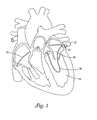
- FIG 1 is a perspective view of a cryo therapy apparatus 10 disposed within the pulmonary vein 12. It is believed that one potential cause of atrial fibrillation may include abnormal electrical activity within an isolated focal center within pulmonary vein 12. Atrial fibrillation may, thus, be treatable by ablating abnormal tissue within pulmonary vein 12. Cryo therapy apparatus 10 may be used to cause cold-induced necrosis and/or ablate a portion of pulmonary vein 12 or tissue proximate thereto and may constitute an efficacious treatment for atrial fibrillation.
- cryo therapy apparatus 10 When performing pulmonary vein ablation, cryo therapy apparatus 10 may be maneuvered through the vasculature of a patient, through the left ventricle 14, into the left atrium 16, and proximate pulmonary vein 12. Alternatively, cryo therapy apparatus 10 may also be navigated to pulmonary vein 12 via a trans-septal approach as shown in Figure 1 and indicated by T-S. Cryo therapy apparatus 10 may be formed into a loop configuration to increase surface contact between cryo therapy apparatus 10 and pulmonary vein 12. The use of the loop configuration and increasing surface contact may make it possible for a clinician to ablate the desired portion of pulmonary vein 16. Cryo therapy apparatus 10 may then be used to cause cold-induced necrosis and/or ablation of pulmonary vein 12.
- Cryo therapy apparatus 10 may be manipulated into a loop configuration, for example, by actuation of a pull cord 17.
- Pull cord 17 may be located on the outside of cryo therapy apparatus 10 or may be disposed within cryo therapy apparatus as described below and depicted in Figures 7-9 .
- cryo therapy apparatus 10 may be used to treat a number of other medical conditions.
- cryo therapy and/or cryoplasty may be efficacious in varicose vein treatment of incompetent valves, valvular disease, arrhythmia, mitral valve regurgitation therapy, gastric reflux disease, gastro esophageal reflux disease, GURD, esophageal disease, restenosis, cancer treatment including stomach or uterine cancer, etc.
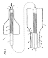
- FIG. 2 is a cross sectional view of cryo therapy apparatus 10.
- Cryo therapy apparatus 10 may include an inner tubular sheath 18, a cooling tube 20 disposed adjacent to tubular sheath 18, an outer tube 22 disposed over at least a portion of cooling tube 20, and a cooling member 24 disposed over at least a portion of cooling tube 20.
- cooling tube 20 may include a distal region 26 including a coil 28 disposed about tubular sheath 18.
- Tubular sheath 18 may comprise a metallic (e.g., stainless steel, nickel-titanium alloy) hypotube having a proximal end 30, a distal end 32, and a lumen 34 extending therethrough.
- Tubular sheath 18 (also suitably described as a core member) may be configured and adapted to be slidably disposed over a core wire 36.
- tubular sheath 18 may be shifted in position relative to core wire 36. This may be useful for altering the site of cold-induced necrosis and/or ablation while allowing core wire 36 to remain stationary.
- Core wire 36 may comprise a guidewire, tube, or other suitable structure.
- Coil 28 is slidably disposed about tubular sheath 18. In some embodiments, coil 28 is slidable disposed along essentially the entire length of sheath 18. In other embodiments, coil 28 is slidable along a portion of the length of sheath 18 (e.g., along all or a portion of the length of cooling member 24.
- Cooling tube 20 may also include, in addition to distal coil 28, a proximal region 38 that may be generally straight and follow the longitudinal axis of tubular sheath 18. Proximal region 38 may terminate at a proximal end (not shown) that may be coupled to a manifold, for example by a luer fitting.
- the manifold may comprise a coolant source and may be capable of delivering an appropriate quantity of coolant to cooling tube 20.
- a portion of coil 28 may be comprised of radiopaque materials.
- a radiopaque material is understood to be capable of producing a relatively bright image on a fluoroscopy screen or another imaging technique during a medical procedure. This relatively bright image aids the user of cryo therapy apparatus 10 in determining the location thereof.
- Radiopaque materials may include, but are not limited to, gold, platinum, tungsten alloy, and plastic material loaded with a radiopaque filler.
- Coil 28, for example, may be at least partially gold-plated.
- cryo therapy apparatus 10 may further comprise additional radiopaque markers.
- Outer tube 22 may be disposed over at least a portion of cooling tube 20 near proximal region 38.
- Outer tube 22 may be metallic, polymeric, or a composite thereof.
- outer tube 22 may comprise polyimide.
- Outer tube 22 may further comprise a support member such as a braid.
- a person of ordinary skill in the art may be familiar with suitable materials and configurations appropriate for the manufacturing of outer tube 22.
- Cooling member 24 may be disposed over at least a portion of cooling tube 20 near distal region 26. Cooling member may be coupled to outer tube 22. Alternatively, outer tube 22 may be coupled to a distal shaft 40. According to this embodiment, distal shaft 40 may, in turn, be coupled to outer tube 22. In different embodiments, cooling member 24 may have different lengths. For example, cooling member 24 may span essentially the length of tubular sheath 14 (e.g., about 100 to 300 centimeters or more). Alternatively, the length of cooling member 24 may span a portion of the length of tubular sheath 14 or be comparable in size to typical angioplasty balloons.
- Cooling member 24 may comprise a LEAP II balloon. LEAP II balloons are comprised of polyether block amide (PEBA). Polyether block amide is commercially available from Atochem Polymers of Birdsboro, Pennsylvania, under the trade name PEBAX. Alternatively, cooling member 24 may comprise a stainless steel or nickel-titanium alloy braid having a heat shrunk polymeric outer layer. Regardless of what material cooling member 24 is comprised of, cooling member may be used by allowing coil 28 may spray coolant onto an inner surface 42 of cooling member 24. Cooling member 24 may then be used to cause cold-induced necrosis or ablate tissue at an area of interest.
- PEBA polyether block amide
- Cryo therapy apparatus 10 may further comprise a tube 44 having a proximal end 46, a distal end 48, and a lumen 50 extending therethrough.
- Lumen 50 may be a lumen that may be used to drain coolant from cooling member 24 if the temperature therein drops below a predetermined point.
- tube 44 may further comprise a temperature sensor 52 that may be used to quantify the temperature proximate cooling member 24.
- FIG. 2A is a cross sectional view of another example cryo therapy apparatus 410, that is essentially the same in form and function as apparatus 10, expect that apparatus 410 includes an outer cooling member 425, a second outer tube 423, and defines an annular lumen 476 between second outer tube 423 and outer tube 22.
- Outer cooling member 425 may provide apparatus with a number of desirable characteristics. For example, outer cooling member 425 may increase the strength of apparatus 10, enhance the safety of apparatus 10, alter or enhance the cooling ability of apparatus 10, etc.
- annular lumen 476 may be maintained under vacuum.
- the proximal end of second outer tube 423 may be coupled to a vacuum device or manifold. Maintaining a vacuum along the length of second outer tube 423 may insulate tube 423 to minimize heat exchange along tube 423.
- the substance can be removed by aspiration.
- FIG. 3 is a cross sectional view of coil 28.
- Coil 28 may include at least one opening 54. Coolant passing through cooling tube 20 may pass through opening 54 and be sprayed onto inner surface 42 of cooling member 24. Multiple embodiments of coil 28 may include differing configurations and numbers of openings. Alterations in the number of openings or configuration of opening may be made without departing from the spirit of the invention. For example, coil 28 may include 2, 4, 6, or 8 openings arranged in a generally circular arrangement such that coolant may be sprayed as a circular ring onto inner surface 42. Spacing between openings 54 may be regular (i.e., 60° separation between 6 openings 54, 45° separation between 8 openings 54, etc.) or may be irregular.
- openings 54 may be configured to allow coolant to be uniformly sprayed onto inner surface 42.
- openings 54 may be configured to have a frusto-conical shape in order to uniformly spray coolant.
- openings 54 may have a flow directing nozzle disposed therein or be configured to have a flow directing nozzle shape in order to impart uniform coolant spray.
- cryo therapy apparatus 10 may be advanced across a lesion or to an area of interest in a conventional manner. Coolant may then be released through openings 54 of cooling tube 20. Cooling may drop the temperature of the tissue at an area of interest to about 0°C to -81°C and occur over about 2 minutes or over about 1 to 5 minutes.
- the coolant used may include a low freezing point liquid such as an ethanol mixture or a liquefied gas such as N 2 O or CO 2 .
- Liquid N 2 can be used as a general purpose coolant and is particularly useful when freezing of cells within the lesion is desired.
- Freon, N 2 O gas, and CO 2 gas can also be used as coolants.
- Other coolants could be used such as cold saline solution, Fluisol or a mixture of saline solution and ethanol. It is anticipated that coolants such as saline solution could be used when rapid freezing of cells within a lesion is not a treatment goal.
- coolants such as saline solution could be used when rapid freezing of cells within a lesion is not a treatment goal.
- coolants could be used in a similar manner to achieve one or more of the treatment goals.
- Coolant may be used for the purpose of illustration, an example of how coolant may be used is described below.
- Liquid N 2 O may be sprayed from openings 54 onto inner surface 42 of cooling member.
- Regulated back pressure may be maintained along the path followed by the coolant in order to prevent freezing of coolant (i.e., dry ice formation if liquid CO 2 is used).
- Cryo therapy apparatus 10 may then be used to cool (i.e., freezing, causing cold-induced lesions, ablate, etc.) an area of interest, for example the pulmonary vein.
- the size and depth of orifices generated at the area of interest may be measured both before and after ablation by a number of imaging techniques including intracardiac ultrasound.
- Cooling may be the result of both the Joule-Thompson effect and the latent heat of vaporization.
- the Joule-Thompson effect is defined as the cooling effect that comes about when a highly compressed non-ideal gas expands into a region of low pressure.
- the latent heat of vaporization is defined as the heat that is released as the result of the phase change from a liquid to a gas. Depending on the cryogen, the latent heat of vaporization contributes to the majority of the cooling with cryo therapy apparatus 10.
- Openings 54 within coil 28 may be manufactured in a number of differing manners.
- An example of a way to manufacture coil 28 is depicted in Figures 4 and 5.
- Figure 4 is a perspective view of coil 28.
- coil 28 may include a dimple 56 formed into coil 28.
- Dimple 56 may facilitate the forming of opening 54.
- Dimple 56 may define a portion of coil 28 having a decreased thickness.
- coil 28 may have a diameter of about 0.008 inches and the diameter proximate coil 28 may be about 0.004 inches.
- the aforementioned design creates a uniform spray field for large area cryogen distribution. Alternative sizes and dimensions may be used without changing the scope of the invention.
- FIG. 5 is a side view of coil 28 taken through line 4-4.
- Opening 54 may be formed into coil 28 at dimple 56 by a number of differing methods. For example, a cobalt puncture bit may be used to drill a hole into coil 28, thus defining opening 54.
- Opening 54 may have a diameter or cross-sectional area D of about 0.002 inches or may have a diameter less than about 0.010 inches.
- FIG. 6 is a cross sectional view of an alternate cryo therapy apparatus 110.
- Cryo therapy apparatus 110 may have many of the feature described for cryo therapy apparatus 10 above and may include a cooling tube 120 slidably disposed over a core member 136.
- Core member 136 may include a distal end 158 having a generally tapered distal tip 160 coupled thereto.
- Core member 136 may comprise a stainless steel or nickel-titanium alloy core wire or may, alternatively, comprise a tubular sheath (similar to tubular sheath 18) adapted to be passed over a core wire.
- distal tip 160 may further comprise a channel that a guidewire may pass through.
- coil 128 is shown to be configured co-axially relative to core member 136, it can be appreciated that coil 128 could also be configured parallel to core member 136 or otherwise disposed within cooling member 124. Other embodiments of apparatus 110 do not include core member 136. According to these embodiments, coil 128 can be described as being slidably disposed within cooling member 124.
- Cooling member 124 may comprise a polymeric heat shrink outer tube 162 disposed over a support member 164.
- Support member 164 may comprise a stainless steel or nickel-titanium alloy braid. Similar to what is described above, coolant may be sprayed onto inner surface 142 of cooling member 124 such that cooling member may be used for cold-induced necrosis and/or ablation of tissue.
- distal tip 160 may also be coupled to support member 164, for example by soldering.
- Outer tube 120 may be coupled to cooling member 124.
- cooling tube 120 may include a coil 128 disposed proximate distal end 158 of core member 136.
- Coil 128 may include at least one opening 154 adapted to spray coolant onto an inner surface 142 of cooling member 124.
- Coil 128 may be slidable along the length of core member 136. This feature may allow heat exchange to occur at a number of points along the length of cooling member 124.
- Cryo therapy apparatus 110 may also include tube 144 that may be similar to that described above.
- tube 144 may be coupled directly to cooling tube 120.
- tube 144 would be slidable relative to core member 156.
- tube 144 may be coupled to cooling tube 120 such that movement of cooling tube 120 relative to core member 156 may result in substantially similar movement of tube 144.
- FIG. 7 is a cross sectional view of a cryo therapy apparatus 210 device having a pull cord 266. It should be noted that the use of pull cord 266 may be applicable to other embodiments of a cryo therapy apparatus including those described herein.
- Pull cord 266 may have a proximal end that is directly or indirectly accessible to the clinician and a distal end 268. Distal end 268 may be coupled to any one of a number of locations along the length of cryo therapy apparatus 210. For example, distal end 268 of pull cord 266 may be coupled to coil 228. Alternatively, distal end 268 may be coupled to core member 256.
- FIG 8 is a cross sectional view of cryo therapy apparatus 210 wherein pull cord 266 is actuated in order to alter the position of cryo therapy apparatus 210. Also shown in Figure 8 is an optional sheath 270 disposed within apparatus 210 for at least a portion of pull cord 266 to pass through. By actuating pull cord 266, cryo therapy apparatus 210 may be bent or otherwise altered into a number of differing shapes and configurations. A person of ordinary skill in the art may be familiar with different configurations appropriate for multiple embodiments of the invention.
- coil 228 may be slidable along core member 256 (or, more generally, slidable within cooling chamber 224) and can be slid toward the distal end of cooling chamber 224.
- coil 228 can be advanced to a necked distal region 272 disposed at the distal end of cooling chamber 224. This may aid deflection of apparatus 210 when pull cord 266 is actuated. More particularly, advancing coil 256 to a position adjacent necked distal region 272 may allow a clinician to deflect the distal end of apparatus 210 as appropriate.
- a portion of pull cord 266 may be located outside or extend out of the distal end of cryo therapy apparatus 210.
- Figure 9 illustrates cryo therapy apparatus 310 in a loop configuration with pull cord 366 extending out of the distal end of apparatus 310.
- Apparatus 310 is essentially the same in form and function as other cryo therapy apparatuses described herein and may include a catheter sheath 374 disposed over at least a portion thereof.
- Pull cord 366 (which may or may not be directly coupled to coil 328) can extend out of the distal end of apparatus 310, loop back into sheath 374, and then extend back in the proximal direction where it would be accessible to a clinician.
- pull cord 366 may comprise an elongate shaft or guidewire 336.
- apparatus 310 may also include a second pull cord (indicated by reference number 366') that can be used in a manner essentially the same as pull cord 266 of Figures 7 and 8 .
Landscapes
- Health & Medical Sciences (AREA)
- Surgery (AREA)
- Life Sciences & Earth Sciences (AREA)
- Nuclear Medicine, Radiotherapy & Molecular Imaging (AREA)
- Animal Behavior & Ethology (AREA)
- General Health & Medical Sciences (AREA)
- Biomedical Technology (AREA)
- Heart & Thoracic Surgery (AREA)
- Medical Informatics (AREA)
- Molecular Biology (AREA)
- Otolaryngology (AREA)
- Engineering & Computer Science (AREA)
- Public Health (AREA)
- Veterinary Medicine (AREA)
- Surgical Instruments (AREA)
- Magnetic Treatment Devices (AREA)
- Particle Accelerators (AREA)
- Discharge Heating (AREA)
- Fixed Capacitors And Capacitor Manufacturing Machines (AREA)
- Media Introduction/Drainage Providing Device (AREA)
Applications Claiming Priority (3)
| Application Number | Priority Date | Filing Date | Title |
|---|---|---|---|
| US10/231,738 US6929639B2 (en) | 2002-08-30 | 2002-08-30 | Cryo ablation coil |
| US231738 | 2002-08-30 | ||
| PCT/US2003/024129 WO2004019798A1 (en) | 2002-08-30 | 2003-07-31 | Cryo ablation coil |
Publications (2)
| Publication Number | Publication Date |
|---|---|
| EP1531747A1 EP1531747A1 (en) | 2005-05-25 |
| EP1531747B1 true EP1531747B1 (en) | 2012-01-11 |
Family
ID=31976800
Family Applications (1)
| Application Number | Title | Priority Date | Filing Date |
|---|---|---|---|
| EP03748998A Expired - Lifetime EP1531747B1 (en) | 2002-08-30 | 2003-07-31 | Cryo ablation coil |
Country Status (7)
| Country | Link |
|---|---|
| US (2) | US6929639B2 (enExample) |
| EP (1) | EP1531747B1 (enExample) |
| JP (1) | JP4416654B2 (enExample) |
| AT (1) | ATE540632T1 (enExample) |
| AU (1) | AU2003268047A1 (enExample) |
| CA (1) | CA2496575C (enExample) |
| WO (1) | WO2004019798A1 (enExample) |
Families Citing this family (148)
| Publication number | Priority date | Publication date | Assignee | Title |
|---|---|---|---|---|
| US7363071B2 (en) | 1999-05-26 | 2008-04-22 | Endocare, Inc. | Computer guided ablation of tissue using integrated ablative/temperature sensing devices |
| AU2002333102A1 (en) * | 2002-02-22 | 2003-09-09 | Bombardier Inc. | A three-wheeled vehicle having a split radiator and an interior storage compartment |
| US7756583B2 (en) | 2002-04-08 | 2010-07-13 | Ardian, Inc. | Methods and apparatus for intravascularly-induced neuromodulation |
| US8347891B2 (en) | 2002-04-08 | 2013-01-08 | Medtronic Ardian Luxembourg S.A.R.L. | Methods and apparatus for performing a non-continuous circumferential treatment of a body lumen |
| ES2564694T3 (es) | 2003-09-12 | 2016-03-28 | Vessix Vascular, Inc. | Sistema de remodelación y / o ablación excéntrica seleccionable de material ateroesclerótico |
| EP1706050A2 (en) | 2003-12-22 | 2006-10-04 | AMS Research Corporation | Cryosurgical devices and methods for endometrial ablation |
| US7291142B2 (en) * | 2004-05-10 | 2007-11-06 | Boston Scientific Scimed, Inc. | Low temperature lesion formation apparatus, systems and methods |
| US7288088B2 (en) * | 2004-05-10 | 2007-10-30 | Boston Scientific Scimed, Inc. | Clamp based low temperature lesion formation apparatus, systems and methods |
| US7582083B2 (en) | 2004-05-10 | 2009-09-01 | Boston Scientific Scimed, Inc. | Probe based low temperature lesion formation apparatus, systems and methods |
| US8396548B2 (en) | 2008-11-14 | 2013-03-12 | Vessix Vascular, Inc. | Selective drug delivery in a lumen |
| US9713730B2 (en) | 2004-09-10 | 2017-07-25 | Boston Scientific Scimed, Inc. | Apparatus and method for treatment of in-stent restenosis |
| US20060069385A1 (en) * | 2004-09-28 | 2006-03-30 | Scimed Life Systems, Inc. | Methods and apparatus for tissue cryotherapy |
| US7740627B2 (en) | 2005-04-29 | 2010-06-22 | Medtronic Cryocath Lp | Surgical method and apparatus for treating atrial fibrillation |
| US7794455B2 (en) | 2005-04-29 | 2010-09-14 | Medtronic Cryocath Lp | Wide area ablation of myocardial tissue |
| US20060270981A1 (en) * | 2005-05-13 | 2006-11-30 | Leonilda Capuano | Coiled injection tube |
| US8992515B2 (en) | 2005-05-13 | 2015-03-31 | Medtronic Cryocath Lp | Coolant injection tube |
| US8019435B2 (en) | 2006-05-02 | 2011-09-13 | Boston Scientific Scimed, Inc. | Control of arterial smooth muscle tone |
| CA2905086C (en) * | 2006-05-12 | 2021-03-30 | Hira V. Thapliyal | Device for ablating body tissue |
| US9211393B2 (en) * | 2006-06-05 | 2015-12-15 | Medtronic Cryocath Lp | Distal cooling distribution system for a medical device |
| ES2560006T3 (es) | 2006-10-18 | 2016-02-17 | Vessix Vascular, Inc. | Inducción de efectos de temperatura deseables sobre tejido corporal |
| WO2008049087A2 (en) | 2006-10-18 | 2008-04-24 | Minnow Medical, Inc. | System for inducing desirable temperature effects on body tissue |
| EP2076193A4 (en) | 2006-10-18 | 2010-02-03 | Minnow Medical Inc | MATCHED RF-ENERGY AND ELECTRO-TISSUE CHARACTERIZATION FOR THE SELECTIVE TREATMENT OF TARGET TISSUE |
| US20080161890A1 (en) * | 2007-01-03 | 2008-07-03 | Boston Scientific Scimed, Inc. | Methods, systems, and apparatuses for protecting esophageal tissue during ablation |
| EP2022397A1 (en) * | 2007-08-08 | 2009-02-11 | ProRhythm, Inc. | Miniature circular mapping catheter |
| WO2009128014A1 (en) * | 2008-04-16 | 2009-10-22 | Arbel Medical Ltd | Cryosurgical instrument with enhanced heat exchange |
| US9155588B2 (en) | 2008-06-13 | 2015-10-13 | Vytronus, Inc. | System and method for positioning an elongate member with respect to an anatomical structure |
| EP2296573B1 (en) * | 2008-06-14 | 2019-09-25 | Vytronus, Inc. | System for delivering energy to tissue |
| WO2009153755A2 (en) * | 2008-06-18 | 2009-12-23 | Arbel Medical Ltd. | Cryosurgical instrument insulating system |
| US8945106B2 (en) * | 2008-07-03 | 2015-02-03 | Steve Arless | Tip design for cryogenic probe with inner coil injection tube |
| US10363057B2 (en) | 2008-07-18 | 2019-07-30 | Vytronus, Inc. | System and method for delivering energy to tissue |
| EP2147662A1 (en) * | 2008-07-23 | 2010-01-27 | Abbott Laboratories Vascular Enterprises Limited | Stent delivery system |
| WO2010033785A1 (en) * | 2008-09-22 | 2010-03-25 | Boston Scientific Scimed, Inc. | Biasing a catheter balloon |
| US20100076634A1 (en) * | 2008-09-22 | 2010-03-25 | Ford Global Technologies, Llc | Method for Controlling a Micro-Hybrid Electric Vehicle with an Automatic Transmission |
| US10695126B2 (en) | 2008-10-06 | 2020-06-30 | Santa Anna Tech Llc | Catheter with a double balloon structure to generate and apply a heated ablative zone to tissue |
| US8465481B2 (en) * | 2008-10-20 | 2013-06-18 | Boston Scientific Scimed, Inc. | Providing cryotherapy with a balloon catheter having a non-uniform thermal profile |
| US9192789B2 (en) * | 2008-10-30 | 2015-11-24 | Vytronus, Inc. | System and method for anatomical mapping of tissue and planning ablation paths therein |
| US8414508B2 (en) | 2008-10-30 | 2013-04-09 | Vytronus, Inc. | System and method for delivery of energy to tissue while compensating for collateral tissue |
| US9033885B2 (en) * | 2008-10-30 | 2015-05-19 | Vytronus, Inc. | System and method for energy delivery to tissue while monitoring position, lesion depth, and wall motion |
| US11298568B2 (en) | 2008-10-30 | 2022-04-12 | Auris Health, Inc. | System and method for energy delivery to tissue while monitoring position, lesion depth, and wall motion |
| US9220924B2 (en) | 2008-10-30 | 2015-12-29 | Vytronus, Inc. | System and method for energy delivery to tissue while monitoring position, lesion depth, and wall motion |
| US8475379B2 (en) * | 2008-11-17 | 2013-07-02 | Vytronus, Inc. | Systems and methods for ablating body tissue |
| KR20110104504A (ko) | 2008-11-17 | 2011-09-22 | 미노우 메디컬, 인코포레이티드 | 조직 토폴로지의 지식 여하에 따른 에너지의 선택적 축적 |
| JP5941281B2 (ja) | 2008-11-17 | 2016-06-29 | バイトロナス, インコーポレイテッド | 体組織を切除するシステムおよび方法 |
| US8382746B2 (en) | 2008-11-21 | 2013-02-26 | C2 Therapeutics, Inc. | Cryogenic ablation system and method |
| JP4988044B2 (ja) * | 2008-12-19 | 2012-08-01 | 有限会社日本エレクテル | バルーンカテーテルシステム |
| WO2010081062A1 (en) * | 2009-01-12 | 2010-07-15 | Boston Scientific Scimed, Inc. | Systems and methods of making and using a coiled coolant transfer tube for a catheter of a cryoablation system |
| US20110257563A1 (en) | 2009-10-26 | 2011-10-20 | Vytronus, Inc. | Methods and systems for ablating tissue |
| US20110263921A1 (en) | 2009-12-31 | 2011-10-27 | Anthony Vrba | Patterned Denervation Therapy for Innervated Renal Vasculature |
| US20110270238A1 (en) | 2009-12-31 | 2011-11-03 | Raed Rizq | Compliant Cryoballoon Apparatus for Denervating Ostia of the Renal Arteries |
| US8926602B2 (en) | 2010-01-28 | 2015-01-06 | Medtronic Cryocath Lp | Triple balloon catheter |
| US20120089211A1 (en) * | 2010-04-08 | 2012-04-12 | Myoscience, Inc. | Methods and apparatus for cryogenically treating multiple tissue sites with a single puncture |
| CN103068330B (zh) | 2010-04-09 | 2016-06-29 | Vessix血管股份有限公司 | 用于治疗组织的功率发生和控制装置 |
| US9192790B2 (en) | 2010-04-14 | 2015-11-24 | Boston Scientific Scimed, Inc. | Focused ultrasonic renal denervation |
| US8473067B2 (en) | 2010-06-11 | 2013-06-25 | Boston Scientific Scimed, Inc. | Renal denervation and stimulation employing wireless vascular energy transfer arrangement |
| US9358365B2 (en) | 2010-07-30 | 2016-06-07 | Boston Scientific Scimed, Inc. | Precision electrode movement control for renal nerve ablation |
| US9408661B2 (en) | 2010-07-30 | 2016-08-09 | Patrick A. Haverkost | RF electrodes on multiple flexible wires for renal nerve ablation |
| US9463062B2 (en) | 2010-07-30 | 2016-10-11 | Boston Scientific Scimed, Inc. | Cooled conductive balloon RF catheter for renal nerve ablation |
| US9155589B2 (en) | 2010-07-30 | 2015-10-13 | Boston Scientific Scimed, Inc. | Sequential activation RF electrode set for renal nerve ablation |
| US9084609B2 (en) | 2010-07-30 | 2015-07-21 | Boston Scientific Scime, Inc. | Spiral balloon catheter for renal nerve ablation |
| US20120029512A1 (en) | 2010-07-30 | 2012-02-02 | Willard Martin R | Balloon with surface electrodes and integral cooling for renal nerve ablation |
| CA2807277C (en) | 2010-08-05 | 2020-05-12 | Medtronic Ardian Luxembourg S.A.R.L. | Cryoablation apparatuses, systems, and methods for renal neuromodulation |
| US8974451B2 (en) | 2010-10-25 | 2015-03-10 | Boston Scientific Scimed, Inc. | Renal nerve ablation using conductive fluid jet and RF energy |
| US9066713B2 (en) | 2010-10-26 | 2015-06-30 | Medtronic Ardian Luxembourg S.A.R.L. | Neuromodulation cryotherapeutic devices and associated systems and methods |
| US9220558B2 (en) | 2010-10-27 | 2015-12-29 | Boston Scientific Scimed, Inc. | RF renal denervation catheter with multiple independent electrodes |
| US9028485B2 (en) | 2010-11-15 | 2015-05-12 | Boston Scientific Scimed, Inc. | Self-expanding cooling electrode for renal nerve ablation |
| US9089350B2 (en) | 2010-11-16 | 2015-07-28 | Boston Scientific Scimed, Inc. | Renal denervation catheter with RF electrode and integral contrast dye injection arrangement |
| US9668811B2 (en) | 2010-11-16 | 2017-06-06 | Boston Scientific Scimed, Inc. | Minimally invasive access for renal nerve ablation |
| US9326751B2 (en) | 2010-11-17 | 2016-05-03 | Boston Scientific Scimed, Inc. | Catheter guidance of external energy for renal denervation |
| US9060761B2 (en) | 2010-11-18 | 2015-06-23 | Boston Scientific Scime, Inc. | Catheter-focused magnetic field induced renal nerve ablation |
| US9192435B2 (en) | 2010-11-22 | 2015-11-24 | Boston Scientific Scimed, Inc. | Renal denervation catheter with cooled RF electrode |
| US9023034B2 (en) | 2010-11-22 | 2015-05-05 | Boston Scientific Scimed, Inc. | Renal ablation electrode with force-activatable conduction apparatus |
| US20120157993A1 (en) | 2010-12-15 | 2012-06-21 | Jenson Mark L | Bipolar Off-Wall Electrode Device for Renal Nerve Ablation |
| WO2012100095A1 (en) | 2011-01-19 | 2012-07-26 | Boston Scientific Scimed, Inc. | Guide-compatible large-electrode catheter for renal nerve ablation with reduced arterial injury |
| EP2694150A1 (en) | 2011-04-08 | 2014-02-12 | Covidien LP | Iontophoresis drug delivery system and method for denervation of the renal sympathetic nerve and iontophoretic drug delivery |
| TW201242570A (en) | 2011-04-25 | 2012-11-01 | Medtronic Ardian Luxembourg | Apparatus and methods related to constrained deployment of cryogenic balloons for limited cryogenic ablation of vessel walls |
| US20120283722A1 (en) * | 2011-05-02 | 2012-11-08 | Medtronic Ablation Frontiers Llc | Adiabatic cooling system for medical devices |
| WO2012154195A1 (en) * | 2011-05-11 | 2012-11-15 | Icecure Medical Ltd. | Coiled heat exchanger for cryosurgical instrument |
| WO2013013156A2 (en) | 2011-07-20 | 2013-01-24 | Boston Scientific Scimed, Inc. | Percutaneous devices and methods to visualize, target and ablate nerves |
| EP2734264B1 (en) | 2011-07-22 | 2018-11-21 | Boston Scientific Scimed, Inc. | Nerve modulation system with a nerve modulation element positionable in a helical guide |
| US9387031B2 (en) | 2011-07-29 | 2016-07-12 | Medtronic Ablation Frontiers Llc | Mesh-overlayed ablation and mapping device |
| WO2013055826A1 (en) | 2011-10-10 | 2013-04-18 | Boston Scientific Scimed, Inc. | Medical devices including ablation electrodes |
| EP2765940B1 (en) | 2011-10-11 | 2015-08-26 | Boston Scientific Scimed, Inc. | Off-wall electrode device for nerve modulation |
| US9420955B2 (en) | 2011-10-11 | 2016-08-23 | Boston Scientific Scimed, Inc. | Intravascular temperature monitoring system and method |
| US9364284B2 (en) | 2011-10-12 | 2016-06-14 | Boston Scientific Scimed, Inc. | Method of making an off-wall spacer cage |
| EP2768568B1 (en) | 2011-10-18 | 2020-05-06 | Boston Scientific Scimed, Inc. | Integrated crossing balloon catheter |
| EP2768563B1 (en) | 2011-10-18 | 2016-11-09 | Boston Scientific Scimed, Inc. | Deflectable medical devices |
| US8951251B2 (en) | 2011-11-08 | 2015-02-10 | Boston Scientific Scimed, Inc. | Ostial renal nerve ablation |
| US9119600B2 (en) | 2011-11-15 | 2015-09-01 | Boston Scientific Scimed, Inc. | Device and methods for renal nerve modulation monitoring |
| US9119632B2 (en) | 2011-11-21 | 2015-09-01 | Boston Scientific Scimed, Inc. | Deflectable renal nerve ablation catheter |
| US9265969B2 (en) | 2011-12-21 | 2016-02-23 | Cardiac Pacemakers, Inc. | Methods for modulating cell function |
| AU2012358143B2 (en) | 2011-12-23 | 2015-06-11 | Boston Scientific Scimed, Inc. | Expandable balloon or an electrode pad with a heat sensing device |
| JP2013132364A (ja) * | 2011-12-26 | 2013-07-08 | Nippon Erekuteru:Kk | バルーンカテーテル |
| EP2797534A1 (en) | 2011-12-28 | 2014-11-05 | Boston Scientific Scimed, Inc. | Device and methods for nerve modulation using a novel ablation catheter with polymeric ablative elements |
| US9050106B2 (en) | 2011-12-29 | 2015-06-09 | Boston Scientific Scimed, Inc. | Off-wall electrode device and methods for nerve modulation |
| EP2840991B1 (en) | 2012-04-27 | 2019-05-15 | Medtronic Ardian Luxembourg S.à.r.l. | Cryotherapeutic devices for renal neuromodulation |
| US9241752B2 (en) | 2012-04-27 | 2016-01-26 | Medtronic Ardian Luxembourg S.A.R.L. | Shafts with pressure relief in cryotherapeutic catheters and associated devices, systems, and methods |
| WO2013169927A1 (en) | 2012-05-08 | 2013-11-14 | Boston Scientific Scimed, Inc. | Renal nerve modulation devices |
| CN104540465A (zh) | 2012-08-24 | 2015-04-22 | 波士顿科学西美德公司 | 带有含单独微孔隙区域的球囊的血管内导管 |
| US9113911B2 (en) | 2012-09-06 | 2015-08-25 | Medtronic Ablation Frontiers Llc | Ablation device and method for electroporating tissue cells |
| US9173696B2 (en) | 2012-09-17 | 2015-11-03 | Boston Scientific Scimed, Inc. | Self-positioning electrode system and method for renal nerve modulation |
| WO2014047411A1 (en) | 2012-09-21 | 2014-03-27 | Boston Scientific Scimed, Inc. | System for nerve modulation and innocuous thermal gradient nerve block |
| US10549127B2 (en) | 2012-09-21 | 2020-02-04 | Boston Scientific Scimed, Inc. | Self-cooling ultrasound ablation catheter |
| EP2906135A2 (en) | 2012-10-10 | 2015-08-19 | Boston Scientific Scimed, Inc. | Renal nerve modulation devices and methods |
| WO2014143571A1 (en) | 2013-03-11 | 2014-09-18 | Boston Scientific Scimed, Inc. | Medical devices for modulating nerves |
| US9956033B2 (en) | 2013-03-11 | 2018-05-01 | Boston Scientific Scimed, Inc. | Medical devices for modulating nerves |
| US9808311B2 (en) | 2013-03-13 | 2017-11-07 | Boston Scientific Scimed, Inc. | Deflectable medical devices |
| WO2014149690A2 (en) | 2013-03-15 | 2014-09-25 | Boston Scientific Scimed, Inc. | Medical devices and methods for treatment of hypertension that utilize impedance compensation |
| US10265122B2 (en) | 2013-03-15 | 2019-04-23 | Boston Scientific Scimed, Inc. | Nerve ablation devices and related methods of use |
| US10105159B2 (en) * | 2013-03-15 | 2018-10-23 | W.L. Gore Associates, Inc | Recanalization device |
| US9827039B2 (en) | 2013-03-15 | 2017-11-28 | Boston Scientific Scimed, Inc. | Methods and apparatuses for remodeling tissue of or adjacent to a body passage |
| WO2014205399A1 (en) | 2013-06-21 | 2014-12-24 | Boston Scientific Scimed, Inc. | Medical devices for renal nerve ablation having rotatable shafts |
| US9943365B2 (en) | 2013-06-21 | 2018-04-17 | Boston Scientific Scimed, Inc. | Renal denervation balloon catheter with ride along electrode support |
| US9707036B2 (en) | 2013-06-25 | 2017-07-18 | Boston Scientific Scimed, Inc. | Devices and methods for nerve modulation using localized indifferent electrodes |
| AU2014284558B2 (en) | 2013-07-01 | 2017-08-17 | Boston Scientific Scimed, Inc. | Medical devices for renal nerve ablation |
| US10660698B2 (en) | 2013-07-11 | 2020-05-26 | Boston Scientific Scimed, Inc. | Devices and methods for nerve modulation |
| US10413357B2 (en) | 2013-07-11 | 2019-09-17 | Boston Scientific Scimed, Inc. | Medical device with stretchable electrode assemblies |
| WO2015010074A1 (en) | 2013-07-19 | 2015-01-22 | Boston Scientific Scimed, Inc. | Spiral bipolar electrode renal denervation balloon |
| EP3024406B1 (en) | 2013-07-22 | 2019-06-19 | Boston Scientific Scimed, Inc. | Medical devices for renal nerve ablation |
| EP3024405A1 (en) | 2013-07-22 | 2016-06-01 | Boston Scientific Scimed, Inc. | Renal nerve ablation catheter having twist balloon |
| JP6159888B2 (ja) | 2013-08-22 | 2017-07-05 | ボストン サイエンティフィック サイムド,インコーポレイテッドBoston Scientific Scimed,Inc. | 腎神経変調バルーンへの接着性を向上させたフレキシブル回路 |
| US9895194B2 (en) | 2013-09-04 | 2018-02-20 | Boston Scientific Scimed, Inc. | Radio frequency (RF) balloon catheter having flushing and cooling capability |
| EP3043733A1 (en) | 2013-09-13 | 2016-07-20 | Boston Scientific Scimed, Inc. | Ablation balloon with vapor deposited cover layer |
| BR112016006214B1 (pt) | 2013-09-24 | 2022-09-13 | Adagio Medical, Inc | Cateter de crioablação |
| US11246654B2 (en) | 2013-10-14 | 2022-02-15 | Boston Scientific Scimed, Inc. | Flexible renal nerve ablation devices and related methods of use and manufacture |
| US9687166B2 (en) | 2013-10-14 | 2017-06-27 | Boston Scientific Scimed, Inc. | High resolution cardiac mapping electrode array catheter |
| US9770606B2 (en) | 2013-10-15 | 2017-09-26 | Boston Scientific Scimed, Inc. | Ultrasound ablation catheter with cooling infusion and centering basket |
| WO2015057584A1 (en) | 2013-10-15 | 2015-04-23 | Boston Scientific Scimed, Inc. | Medical device balloon |
| EP3057521B1 (en) | 2013-10-18 | 2020-03-25 | Boston Scientific Scimed, Inc. | Balloon catheters with flexible conducting wires |
| JP2016534842A (ja) | 2013-10-25 | 2016-11-10 | ボストン サイエンティフィック サイムド,インコーポレイテッドBoston Scientific Scimed,Inc. | 除神経フレックス回路における埋め込み熱電対 |
| CN105899157B (zh) | 2014-01-06 | 2019-08-09 | 波士顿科学国际有限公司 | 抗撕裂柔性电路组件 |
| US9907609B2 (en) | 2014-02-04 | 2018-03-06 | Boston Scientific Scimed, Inc. | Alternative placement of thermal sensors on bipolar electrode |
| US11000679B2 (en) | 2014-02-04 | 2021-05-11 | Boston Scientific Scimed, Inc. | Balloon protection and rewrapping devices and related methods of use |
| US10492842B2 (en) | 2014-03-07 | 2019-12-03 | Medtronic Ardian Luxembourg S.A.R.L. | Monitoring and controlling internally administered cryotherapy |
| WO2015157667A1 (en) * | 2014-04-11 | 2015-10-15 | Jeremy Stigall | Imaging and treatment device |
| US10709490B2 (en) | 2014-05-07 | 2020-07-14 | Medtronic Ardian Luxembourg S.A.R.L. | Catheter assemblies comprising a direct heating element for renal neuromodulation and associated systems and methods |
| US9414878B1 (en) | 2015-05-15 | 2016-08-16 | C2 Therapeutics, Inc. | Cryogenic balloon ablation system |
| US10549128B2 (en) | 2015-11-04 | 2020-02-04 | Vytronus, Inc. | Systems and methods for imaging and ablating tissue |
| US12364537B2 (en) | 2016-05-02 | 2025-07-22 | Santa Anna Tech Llc | Catheter with a double balloon structure to generate and apply a heated ablative zone to tissue |
| US11331140B2 (en) | 2016-05-19 | 2022-05-17 | Aqua Heart, Inc. | Heated vapor ablation systems and methods for treating cardiac conditions |
| CN109414284B (zh) | 2016-05-20 | 2021-08-10 | 美国宾得公司 | 具有可旋转并且可平移的导管的低温消融系统 |
| CA3073403A1 (en) | 2017-09-05 | 2019-03-14 | Adagio Medical, Inc. | Ablation catheter having a shape memory stylet |
| WO2019071269A2 (en) | 2017-10-06 | 2019-04-11 | Powell Charles Lee | SYSTEM AND METHOD FOR TREATING AN OBSTRUCTIVE SLEEP APNEA |
| US11419657B2 (en) | 2017-11-30 | 2022-08-23 | Boston Scientific Scimed, Inc. | Compensation assembly for fluid injection line of intravascular catheter system |
| US11751930B2 (en) | 2018-01-10 | 2023-09-12 | Adagio Medical, Inc. | Cryoablation element with conductive liner |
| CN115315221B (zh) * | 2019-08-14 | 2025-05-13 | 生物相容英国有限公司 | 双级低温冷却器 |
| US11633224B2 (en) | 2020-02-10 | 2023-04-25 | Icecure Medical Ltd. | Cryogen pump |
| US12426934B2 (en) | 2022-02-28 | 2025-09-30 | Icecure Medical Ltd. | Cryogen flow control |
| US12215811B2 (en) | 2022-07-18 | 2025-02-04 | Icecure Medical Ltd. | Cryogenic system connector |
Family Cites Families (16)
| Publication number | Priority date | Publication date | Assignee | Title |
|---|---|---|---|---|
| DE2831199C3 (de) | 1978-07-15 | 1981-01-08 | Erbe Elektromedizin Gmbh & Co Kg, 7400 Tuebingen | Kryochirurgiegerät |
| US5135531A (en) * | 1984-05-14 | 1992-08-04 | Surgical Systems & Instruments, Inc. | Guided atherectomy system |
| US5147355A (en) | 1988-09-23 | 1992-09-15 | Brigham And Womens Hospital | Cryoablation catheter and method of performing cryoablation |
| US5624392A (en) | 1990-05-11 | 1997-04-29 | Saab; Mark A. | Heat transfer catheters and methods of making and using same |
| US5281215A (en) | 1992-04-16 | 1994-01-25 | Implemed, Inc. | Cryogenic catheter |
| US5334193A (en) | 1992-11-13 | 1994-08-02 | American Cardiac Ablation Co., Inc. | Fluid cooled ablation catheter |
| NL9301851A (nl) | 1993-10-26 | 1995-05-16 | Cordis Europ | Cryo-ablatie catheter. |
| GB2283678B (en) | 1993-11-09 | 1998-06-03 | Spembly Medical Ltd | Cryosurgical catheter probe |
| US5868735A (en) | 1997-03-06 | 1999-02-09 | Scimed Life Systems, Inc. | Cryoplasty device and method |
| US7220257B1 (en) | 2000-07-25 | 2007-05-22 | Scimed Life Systems, Inc. | Cryotreatment device and method |
| US6024740A (en) | 1997-07-08 | 2000-02-15 | The Regents Of The University Of California | Circumferential ablation device assembly |
| US5971979A (en) | 1997-12-02 | 1999-10-26 | Odyssey Technologies, Inc. | Method for cryogenic inhibition of hyperplasia |
| US6685732B2 (en) | 1998-03-31 | 2004-02-03 | Innercool Therapies, Inc. | Method and device for performing cooling- or cryo-therapies for, e.g., angioplasty with reduced restenosis or pulmonary vein cell necrosis to inhibit atrial fibrillation employing microporous balloon |
| US7291144B2 (en) | 1998-03-31 | 2007-11-06 | Innercool Therapies, Inc. | Method and device for performing cooling- or cryo-therapies for, e.g., angioplasty with reduced restenosis or pulmonary vein cell necrosis to inhibit atrial fibrillation |
| EP1087713A4 (en) * | 1998-06-19 | 2003-02-12 | Endocare Inc | SHEATH, CRYOSONDE AND METHODS OF USE THEREOF |
| US6551274B2 (en) | 2000-02-29 | 2003-04-22 | Biosense Webster, Inc. | Cryoablation catheter with an expandable cooling chamber |
-
2002
- 2002-08-30 US US10/231,738 patent/US6929639B2/en not_active Expired - Lifetime
-
2003
- 2003-07-31 AT AT03748998T patent/ATE540632T1/de active
- 2003-07-31 EP EP03748998A patent/EP1531747B1/en not_active Expired - Lifetime
- 2003-07-31 AU AU2003268047A patent/AU2003268047A1/en not_active Abandoned
- 2003-07-31 JP JP2004532847A patent/JP4416654B2/ja not_active Expired - Fee Related
- 2003-07-31 WO PCT/US2003/024129 patent/WO2004019798A1/en not_active Ceased
- 2003-07-31 CA CA2496575A patent/CA2496575C/en not_active Expired - Fee Related
-
2005
- 2005-03-31 US US11/094,863 patent/US7172589B2/en not_active Expired - Lifetime
Also Published As
| Publication number | Publication date |
|---|---|
| EP1531747A1 (en) | 2005-05-25 |
| AU2003268047A1 (en) | 2004-03-19 |
| JP4416654B2 (ja) | 2010-02-17 |
| US20040044334A1 (en) | 2004-03-04 |
| CA2496575A1 (en) | 2004-03-11 |
| US20050182396A1 (en) | 2005-08-18 |
| JP2005537089A (ja) | 2005-12-08 |
| CA2496575C (en) | 2012-02-21 |
| WO2004019798A1 (en) | 2004-03-11 |
| ATE540632T1 (de) | 2012-01-15 |
| US7172589B2 (en) | 2007-02-06 |
| US6929639B2 (en) | 2005-08-16 |
Similar Documents
| Publication | Publication Date | Title |
|---|---|---|
| EP1531747B1 (en) | Cryo ablation coil | |
| US7101368B2 (en) | Cryo balloon for atrial ablation | |
| US20230255673A1 (en) | Ablation catheter having a shape memory stylet | |
| JP4833494B2 (ja) | 凍結治療装置および方法 | |
| US11806065B2 (en) | Spray nozzle design for a catheter | |
| US7625369B2 (en) | Method and device for epicardial ablation | |
| JP4653734B2 (ja) | 極低温治療装置及び伝導遮断箇所を形成する方法 | |
| US10070910B2 (en) | Apparatus and methods for cryogenically ablating tissue and adjusting cryogenic ablation regions | |
| US20210315627A1 (en) | Ablation catheter having an expandable treatment portion | |
| US12161382B2 (en) | Flow manifold for cryoablation catheter |
Legal Events
| Date | Code | Title | Description |
|---|---|---|---|
| PUAI | Public reference made under article 153(3) epc to a published international application that has entered the european phase |
Free format text: ORIGINAL CODE: 0009012 |
|
| 17P | Request for examination filed |
Effective date: 20050316 |
|
| AK | Designated contracting states |
Kind code of ref document: A1 Designated state(s): AT BE BG CH CY CZ DE DK EE ES FI FR GB GR HU IE IT LI LU MC NL PT RO SE SI SK TR |
|
| AX | Request for extension of the european patent |
Extension state: AL LT LV MK |
|
| DAX | Request for extension of the european patent (deleted) | ||
| 17Q | First examination report despatched |
Effective date: 20090105 |
|
| GRAP | Despatch of communication of intention to grant a patent |
Free format text: ORIGINAL CODE: EPIDOSNIGR1 |
|
| GRAS | Grant fee paid |
Free format text: ORIGINAL CODE: EPIDOSNIGR3 |
|
| GRAA | (expected) grant |
Free format text: ORIGINAL CODE: 0009210 |
|
| AK | Designated contracting states |
Kind code of ref document: B1 Designated state(s): AT BE BG CH CY CZ DE DK EE ES FI FR GB GR HU IE IT LI LU MC NL PT RO SE SI SK TR |
|
| REG | Reference to a national code |
Ref country code: GB Ref legal event code: FG4D |
|
| REG | Reference to a national code |
Ref country code: CH Ref legal event code: EP |
|
| REG | Reference to a national code |
Ref country code: AT Ref legal event code: REF Ref document number: 540632 Country of ref document: AT Kind code of ref document: T Effective date: 20120115 |
|
| REG | Reference to a national code |
Ref country code: IE Ref legal event code: FG4D |
|
| REG | Reference to a national code |
Ref country code: DE Ref legal event code: R096 Ref document number: 60339685 Country of ref document: DE Effective date: 20120315 |
|
| REG | Reference to a national code |
Ref country code: NL Ref legal event code: VDEP Effective date: 20120111 |
|
| PG25 | Lapsed in a contracting state [announced via postgrant information from national office to epo] |
Ref country code: SI Free format text: LAPSE BECAUSE OF FAILURE TO SUBMIT A TRANSLATION OF THE DESCRIPTION OR TO PAY THE FEE WITHIN THE PRESCRIBED TIME-LIMIT Effective date: 20120111 |
|
| PG25 | Lapsed in a contracting state [announced via postgrant information from national office to epo] |
Ref country code: NL Free format text: LAPSE BECAUSE OF FAILURE TO SUBMIT A TRANSLATION OF THE DESCRIPTION OR TO PAY THE FEE WITHIN THE PRESCRIBED TIME-LIMIT Effective date: 20120111 Ref country code: BE Free format text: LAPSE BECAUSE OF FAILURE TO SUBMIT A TRANSLATION OF THE DESCRIPTION OR TO PAY THE FEE WITHIN THE PRESCRIBED TIME-LIMIT Effective date: 20120111 Ref country code: BG Free format text: LAPSE BECAUSE OF FAILURE TO SUBMIT A TRANSLATION OF THE DESCRIPTION OR TO PAY THE FEE WITHIN THE PRESCRIBED TIME-LIMIT Effective date: 20120411 |
|
| PG25 | Lapsed in a contracting state [announced via postgrant information from national office to epo] |
Ref country code: PT Free format text: LAPSE BECAUSE OF FAILURE TO SUBMIT A TRANSLATION OF THE DESCRIPTION OR TO PAY THE FEE WITHIN THE PRESCRIBED TIME-LIMIT Effective date: 20120511 Ref country code: GR Free format text: LAPSE BECAUSE OF FAILURE TO SUBMIT A TRANSLATION OF THE DESCRIPTION OR TO PAY THE FEE WITHIN THE PRESCRIBED TIME-LIMIT Effective date: 20120412 Ref country code: FI Free format text: LAPSE BECAUSE OF FAILURE TO SUBMIT A TRANSLATION OF THE DESCRIPTION OR TO PAY THE FEE WITHIN THE PRESCRIBED TIME-LIMIT Effective date: 20120111 |
|
| REG | Reference to a national code |
Ref country code: AT Ref legal event code: MK05 Ref document number: 540632 Country of ref document: AT Kind code of ref document: T Effective date: 20120111 |
|
| PG25 | Lapsed in a contracting state [announced via postgrant information from national office to epo] |
Ref country code: CY Free format text: LAPSE BECAUSE OF FAILURE TO SUBMIT A TRANSLATION OF THE DESCRIPTION OR TO PAY THE FEE WITHIN THE PRESCRIBED TIME-LIMIT Effective date: 20120111 |
|
| PG25 | Lapsed in a contracting state [announced via postgrant information from national office to epo] |
Ref country code: RO Free format text: LAPSE BECAUSE OF FAILURE TO SUBMIT A TRANSLATION OF THE DESCRIPTION OR TO PAY THE FEE WITHIN THE PRESCRIBED TIME-LIMIT Effective date: 20120111 Ref country code: EE Free format text: LAPSE BECAUSE OF FAILURE TO SUBMIT A TRANSLATION OF THE DESCRIPTION OR TO PAY THE FEE WITHIN THE PRESCRIBED TIME-LIMIT Effective date: 20120111 Ref country code: CZ Free format text: LAPSE BECAUSE OF FAILURE TO SUBMIT A TRANSLATION OF THE DESCRIPTION OR TO PAY THE FEE WITHIN THE PRESCRIBED TIME-LIMIT Effective date: 20120111 Ref country code: DK Free format text: LAPSE BECAUSE OF FAILURE TO SUBMIT A TRANSLATION OF THE DESCRIPTION OR TO PAY THE FEE WITHIN THE PRESCRIBED TIME-LIMIT Effective date: 20120111 Ref country code: SE Free format text: LAPSE BECAUSE OF FAILURE TO SUBMIT A TRANSLATION OF THE DESCRIPTION OR TO PAY THE FEE WITHIN THE PRESCRIBED TIME-LIMIT Effective date: 20120111 |
|
| PLBE | No opposition filed within time limit |
Free format text: ORIGINAL CODE: 0009261 |
|
| STAA | Information on the status of an ep patent application or granted ep patent |
Free format text: STATUS: NO OPPOSITION FILED WITHIN TIME LIMIT |
|
| PG25 | Lapsed in a contracting state [announced via postgrant information from national office to epo] |
Ref country code: SK Free format text: LAPSE BECAUSE OF FAILURE TO SUBMIT A TRANSLATION OF THE DESCRIPTION OR TO PAY THE FEE WITHIN THE PRESCRIBED TIME-LIMIT Effective date: 20120111 |
|
| 26N | No opposition filed |
Effective date: 20121012 |
|
| PG25 | Lapsed in a contracting state [announced via postgrant information from national office to epo] |
Ref country code: AT Free format text: LAPSE BECAUSE OF FAILURE TO SUBMIT A TRANSLATION OF THE DESCRIPTION OR TO PAY THE FEE WITHIN THE PRESCRIBED TIME-LIMIT Effective date: 20120111 |
|
| REG | Reference to a national code |
Ref country code: DE Ref legal event code: R097 Ref document number: 60339685 Country of ref document: DE Effective date: 20121012 |
|
| PG25 | Lapsed in a contracting state [announced via postgrant information from national office to epo] |
Ref country code: MC Free format text: LAPSE BECAUSE OF NON-PAYMENT OF DUE FEES Effective date: 20120731 |
|
| REG | Reference to a national code |
Ref country code: CH Ref legal event code: PL |
|
| GBPC | Gb: european patent ceased through non-payment of renewal fee |
Effective date: 20120731 |
|
| REG | Reference to a national code |
Ref country code: FR Ref legal event code: ST Effective date: 20130329 |
|
| PG25 | Lapsed in a contracting state [announced via postgrant information from national office to epo] |
Ref country code: GB Free format text: LAPSE BECAUSE OF NON-PAYMENT OF DUE FEES Effective date: 20120731 Ref country code: LI Free format text: LAPSE BECAUSE OF NON-PAYMENT OF DUE FEES Effective date: 20120731 Ref country code: DE Free format text: LAPSE BECAUSE OF NON-PAYMENT OF DUE FEES Effective date: 20130201 Ref country code: FR Free format text: LAPSE BECAUSE OF NON-PAYMENT OF DUE FEES Effective date: 20120731 Ref country code: ES Free format text: LAPSE BECAUSE OF FAILURE TO SUBMIT A TRANSLATION OF THE DESCRIPTION OR TO PAY THE FEE WITHIN THE PRESCRIBED TIME-LIMIT Effective date: 20120422 Ref country code: CH Free format text: LAPSE BECAUSE OF NON-PAYMENT OF DUE FEES Effective date: 20120731 |
|
| REG | Reference to a national code |
Ref country code: IE Ref legal event code: MM4A |
|
| PG25 | Lapsed in a contracting state [announced via postgrant information from national office to epo] |
Ref country code: IT Free format text: LAPSE BECAUSE OF NON-PAYMENT OF DUE FEES Effective date: 20120731 |
|
| PG25 | Lapsed in a contracting state [announced via postgrant information from national office to epo] |
Ref country code: IE Free format text: LAPSE BECAUSE OF NON-PAYMENT OF DUE FEES Effective date: 20120731 |
|
| REG | Reference to a national code |
Ref country code: DE Ref legal event code: R119 Ref document number: 60339685 Country of ref document: DE Effective date: 20130201 |
|
| PG25 | Lapsed in a contracting state [announced via postgrant information from national office to epo] |
Ref country code: TR Free format text: LAPSE BECAUSE OF FAILURE TO SUBMIT A TRANSLATION OF THE DESCRIPTION OR TO PAY THE FEE WITHIN THE PRESCRIBED TIME-LIMIT Effective date: 20120111 |
|
| PG25 | Lapsed in a contracting state [announced via postgrant information from national office to epo] |
Ref country code: LU Free format text: LAPSE BECAUSE OF NON-PAYMENT OF DUE FEES Effective date: 20120731 |
|
| PG25 | Lapsed in a contracting state [announced via postgrant information from national office to epo] |
Ref country code: HU Free format text: LAPSE BECAUSE OF FAILURE TO SUBMIT A TRANSLATION OF THE DESCRIPTION OR TO PAY THE FEE WITHIN THE PRESCRIBED TIME-LIMIT Effective date: 20030731 |