EP1531104A1 - Brake force control system for motorcycle - Google Patents
Brake force control system for motorcycle Download PDFInfo
- Publication number
- EP1531104A1 EP1531104A1 EP04026700A EP04026700A EP1531104A1 EP 1531104 A1 EP1531104 A1 EP 1531104A1 EP 04026700 A EP04026700 A EP 04026700A EP 04026700 A EP04026700 A EP 04026700A EP 1531104 A1 EP1531104 A1 EP 1531104A1
- Authority
- EP
- European Patent Office
- Prior art keywords
- control system
- brake force
- force control
- seat
- motorcycle
- Prior art date
- Legal status (The legal status is an assumption and is not a legal conclusion. Google has not performed a legal analysis and makes no representation as to the accuracy of the status listed.)
- Granted
Links
Images


Classifications
-
- B—PERFORMING OPERATIONS; TRANSPORTING
- B60—VEHICLES IN GENERAL
- B60T—VEHICLE BRAKE CONTROL SYSTEMS OR PARTS THEREOF; BRAKE CONTROL SYSTEMS OR PARTS THEREOF, IN GENERAL; ARRANGEMENT OF BRAKING ELEMENTS ON VEHICLES IN GENERAL; PORTABLE DEVICES FOR PREVENTING UNWANTED MOVEMENT OF VEHICLES; VEHICLE MODIFICATIONS TO FACILITATE COOLING OF BRAKES
- B60T8/00—Arrangements for adjusting wheel-braking force to meet varying vehicular or ground-surface conditions, e.g. limiting or varying distribution of braking force
- B60T8/32—Arrangements for adjusting wheel-braking force to meet varying vehicular or ground-surface conditions, e.g. limiting or varying distribution of braking force responsive to a speed condition, e.g. acceleration or deceleration
- B60T8/321—Arrangements for adjusting wheel-braking force to meet varying vehicular or ground-surface conditions, e.g. limiting or varying distribution of braking force responsive to a speed condition, e.g. acceleration or deceleration deceleration
- B60T8/3225—Systems specially adapted for single-track vehicles, e.g. motorcycles
-
- B—PERFORMING OPERATIONS; TRANSPORTING
- B60—VEHICLES IN GENERAL
- B60T—VEHICLE BRAKE CONTROL SYSTEMS OR PARTS THEREOF; BRAKE CONTROL SYSTEMS OR PARTS THEREOF, IN GENERAL; ARRANGEMENT OF BRAKING ELEMENTS ON VEHICLES IN GENERAL; PORTABLE DEVICES FOR PREVENTING UNWANTED MOVEMENT OF VEHICLES; VEHICLE MODIFICATIONS TO FACILITATE COOLING OF BRAKES
- B60T8/00—Arrangements for adjusting wheel-braking force to meet varying vehicular or ground-surface conditions, e.g. limiting or varying distribution of braking force
- B60T8/32—Arrangements for adjusting wheel-braking force to meet varying vehicular or ground-surface conditions, e.g. limiting or varying distribution of braking force responsive to a speed condition, e.g. acceleration or deceleration
- B60T8/34—Arrangements for adjusting wheel-braking force to meet varying vehicular or ground-surface conditions, e.g. limiting or varying distribution of braking force responsive to a speed condition, e.g. acceleration or deceleration having a fluid pressure regulator responsive to a speed condition
- B60T8/36—Arrangements for adjusting wheel-braking force to meet varying vehicular or ground-surface conditions, e.g. limiting or varying distribution of braking force responsive to a speed condition, e.g. acceleration or deceleration having a fluid pressure regulator responsive to a speed condition including a pilot valve responding to an electromagnetic force
- B60T8/3615—Electromagnetic valves specially adapted for anti-lock brake and traction control systems
- B60T8/3675—Electromagnetic valves specially adapted for anti-lock brake and traction control systems integrated in modulator units
- B60T8/368—Electromagnetic valves specially adapted for anti-lock brake and traction control systems integrated in modulator units combined with other mechanical components, e.g. pump units, master cylinders
- B60T8/3685—Electromagnetic valves specially adapted for anti-lock brake and traction control systems integrated in modulator units combined with other mechanical components, e.g. pump units, master cylinders characterised by the mounting of the modulator unit onto the vehicle
-
- B—PERFORMING OPERATIONS; TRANSPORTING
- B62—LAND VEHICLES FOR TRAVELLING OTHERWISE THAN ON RAILS
- B62L—BRAKES SPECIALLY ADAPTED FOR CYCLES
- B62L3/00—Brake-actuating mechanisms; Arrangements thereof
- B62L3/08—Mechanisms specially adapted for braking more than one wheel
-
- B—PERFORMING OPERATIONS; TRANSPORTING
- B60—VEHICLES IN GENERAL
- B60Y—INDEXING SCHEME RELATING TO ASPECTS CROSS-CUTTING VEHICLE TECHNOLOGY
- B60Y2200/00—Type of vehicle
- B60Y2200/10—Road Vehicles
- B60Y2200/12—Motorcycles, Trikes; Quads; Scooters
Definitions
- the present invention relates to a brake force control system for a motorcycle.
- FIG. 2 of JP 30 94 736 will be described referring to FIG. 11, and FIG. 3 of JP 30 94 736 will be described referring to FIG. 12. Incidentally, symbols have been renewed. Besides, as to FIG. 3 of JP 3094736, only the right half of the figure is shown.
- FIG. 11 is a side view of a motorcycle including a conventional brake force control system.
- a motorcycle 300 is a vehicle provided with a vehicle body frame 314 including a head pipe 301, left and right tank rails 302 and 303 extended rearwardly downwards from the head pipe 301, a left-right pair of seat rails 306 and 307 extended rearwards from respective middle portions of the rank rails 302 and 303, and a left-right pair of seat stays 311 and 312 extended rearwardly upwards from bent portions of the tank rails 302 and 303 and having rear ends connected to the rear ends of the seat rails 306 and 307.
- a pump unit 316 constituting the brake force control system is disposed between the seat rails 306, 307 and the seat stays 311, 312 in side view.
- FIG. 12 is a plan view showing the layout of the conventional brake force control system, showing that a pump unit holder 321 is disposed bridgingly between the left and right seat rails 306 and 307, and a pump unit 316 and a battery 322 are supported by the pump unit holder 321.
- symbols 324 and 325 denote upper portion fixing portions provided at both end portions of the pump unit holder 321 for the purpose of mounting the pump unit holder 321 to the left and right seat rails 306 and 307.
- the pump unit 316 is comprised of a pump 327, and a motor 328 for driving the pump 327, and the brake force control system includes the pump 327, a motor 328, and a controller, a solenoid valve and the like which are not shown in the figure.
- the pump unit 316 is disposed in the space formed between the left and right seat rails 306 and 307, so that the amount of upward movement of a rear wheel 231 must be limited for the purpose of obviating the interference between the pump unit 316 and the rear wheel 231.
- the invention as set forth in claim 1 is characterized in that, in a motorcycle including a vehicle body frame of which a rear portion of the vehicle body frame is comprised of a left-right pair of seat rails extended substantially horizontally rearwards, the rear ends of the seat rails being supported by the rear ends of a left-right pair of seat stays extended rearwardly upwards, and a brake force control system for controlling a brake force for a wheel, the brake force control system being disposed in the vicinity of the seat rail and the seat stay, the brake force control system is disposed at such a position that a central portion thereof or the center of gravity thereof substantially overlaps one of the left and right seat rails in plan view and on the lower side of the one seat rail.
- the brake force control system is disposed at such a position that a central portion thereof or the center of gravity thereof substantially overlaps one of the left and right seat rails and on the lower side of the one seat rail so that a rear wheel does not interfere with the brake force control system when moved upwards.
- the invention as set forth in claim 2 is characterized in that the brake force control system is supported on the seat stay side and is disposed on the upper side of the seat stay.
- the brake force control system is supported on the seat stay side, and a central portion of the brake force control system is disposed to overlap the seat rail in plan view, so as thereby to suppress a moment acting on the seat stay side, for example, on a support member attached to the seat stay for supporting the brake force control system when a vertical force is exerted on the brake force control system.
- the invention as set forth in claim 3 is characterized in that the brake force control system is disposed on the inner side relative to the outermost side of a side cover for covering a side portion of a vehicle body.
- the side cover first makes contact with the ground, whereby the brake force control system is protected.
- the invention as set forth in claim 4 is characterized in that at least a part of the brake force control system overlaps the side cover in side view.
- the brake force control system is covered with the side cover, whereby the brake force control system is protected more securely.
- the invention as set forth in claim 5 is characterized in that a battery is disposed on the lower side of the other seat rail which is opposite to the one seat rail located on the side of the brake force control system.
- the brake force control system and the battery are disposed respectively near the left and right seat rails, whereby a weight balance is secured on the left and right sides of the vehicle body.
- the invention as set forth in claim 6 is characterized in that the brake force control system is held by a bracket fixed to the seat stay, and the bracket includes holding walls for respectively holding a front portion and left and right portions of the brake force control system.
- the front portion and the left and right portions of the brake force control system are held by the holding walls of the bracket, whereby it is made possible to mount and dismount the brake force control system via the rear side of the bracket.
- the invention as set forth in claim 7 is characterized in that the brake force control system includes a pump-motor unit and a control unit, and the control unit is disposed on the outside of the vehicle body relative to the pump-motor unit.
- the control unit is disposed on the outside of the vehicle body relative to the pump-motor unit, and the pump-motor unit is disposed on the inner side of the vehicle body, whereby the heavy body is located near the vehicle body center side, and concentration of mass on the vehicle body center side is contrived.
- control unit includes a coupler portion to be connected to a harness on the vehicle body side, and the coupler portion is provided on the rear side of the pump-motor unit and on the side of a rear portion of the vehicle body.
- the coupler portion is provided on the rear side of the pump-motor unit and on the side of a rear portion of the vehicle body, and is protected by the seat stay.
- the brake force control system is disposed at such a position that a central portion thereof or the center of gravity thereof substantially overlaps one of the left and right seat rails in plan view and on the lower side of the one seat rail. Therefore, the rear wheel does not interfere with the brake force control system even when moved upwards, and the amount of upward movement of the rear wheel can be enlarged. Therefore, in the case of an off-road vehicle, the bad road running performance can be enhanced.
- the brake force control system is supported on the seat rail side, and a central portion of the brake force control system overlaps the seat rail in plan view, so that it is possible to suppress the moment acting on the seat rail side, for example, on a support member mounted to the seat rail for the purpose of supporting the brake force control system when a vertical force is exerted on the brake force control system. Therefore, the rigidity of the support member can be set low, and it is possible to contrive decreases in weight and size of the support member.
- the brake force control system is disposed on the inner side relative to the outermost side of a side cover for covering side portions of the vehicle body. Therefore, when the motorcycle falls down, for example, the side cover first makes contact with the ground, so that the brake force control system can be protected, and reliability can be enhanced.
- At least a part of the brake force control system overlaps the side cover in side view, so that the brake force control system is covered with the side cover and, therefore, the brake force control system can be protected more securely.
- the battery is disposed on the lower side of the other seat rail opposite to the one seat rail located on the side of the brake force control system, so that a good weight balance is obtained on the left and right sides of the vehicle body.
- the front portion and the left and right portions of the brake force control system are held by the holding walls of the bracket, so that the brake force control system can be mounted and dismounted via the rear side of the bracket.
- control unit is disposed on the outside of the vehicle body relative to the pump-motor unit, and the pump-motor unit is disposed on the inner side of the vehicle body, so that the pump-motor unit as a heavy body can be disposed near the vehicle body center side, and concentration of mass on the vehicle body center side can be contrived.
- the coupler portion is provided on the rear side of the pump-motor unit and on the side of a rear portion of the vehicle body, so that the coupler portion can be protected by the seat stay, there is no need for a protective member for exclusive use for the coupler portion, and a reduction in cost can be achieved.
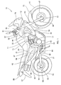
- FIG. 1 is a side view of a motorcycle including a brake force control system according to the present invention.
- the motorcycle 10 is a vehicle in which a front fork 13 is steerably mounted to a head pipe 12 provided at the front end of a vehicle body frame 11, a front wheel 14 is mounted to lower portions of the front fork 13, a steering bar handle 16 is attached to an upper portion of the front fork 13, an engine 17 and a transmission 18 integrally connected to the engine 17 are mounted on the inside of the vehicle body frame 11, a swing arm 21 is vertically swingably mounted to a lower portion of the vehicle body frame 11, and a rear wheel 22 is mounted to the rear end of the swing arm 21.
- an anti-lock brake system (ABS) described below is mounted on the vehicle for the purpose of preventing the front wheel 14 and the rear wheel 22 from being locked at the time of braking.
- ABS anti-lock brake system
- the vehicle body frame 11 is comprised of left and right main frames 31 and 32 (only symbol 32 on the viewer's side is shown) extended rearwardly downwards from the head pipe 12, left and right down frames 33 and 34 (only symbol 34 on the viewer's side is shown) extended substantially downwards from the head pipe 12 and then rearwards and connected respectively to the lower ends of the main frames 31 and 32, a left-right pair of seat rails 36 and 37 (only symbol 37 on the viewer's side is shown) extended substantially horizontally rearwards from bent portions of the main frames 31 and 32, and a left-right pair of seat stays 41 and 42 (only symbol 42 on the viewer's side is shown) extended rearwardly upwards from respective lower portions of the main frames 31 and 32 and connected to the rear ends of the seat rails 36 and 37.
- symbols 43 and 44 denote reinforcing frames disposed bridgingly between the main frames 31, 32 and the down frames 33, 34.
- the front wheel 14 is fitted with a brake disk 47.
- a front wheel disk brake 51 is constituted of the brake disk 47, and a brake caliper 48 attached to the front fork 13 for the purpose of braking by clamping the brake disk 47.
- the rear wheel 22 is fitted with a brake disk 53.
- a rear wheel disk brake 55 is constituted of the brake disk 53, and a brake caliper 54 attached to the swing arm 21 through a bracket for the purpose of braking by clamping the brake disk 53.
- the steering bar handle 16 is a component part fitted with a throttle grip 57 for regulating the opening of a throttle provided in an intake system of the engine 17, a front wheel brake lever 58 for braking the front wheel 14, and a first master cylinder 61 for generating a brake liquid pressure when the front wheel brake lever 58 is operated.
- Symbol 63 denotes a rear wheel brake pedal for braking the rear wheel 22.
- a bracket 64 is attached to a lower portion of the main frame 32, and the rear wheel brake pedal 63 is mounted to the bracket 64.
- Symbol 66 denotes a second master cylinder for generating a brake liquid pressure when the rear wheel brake pedal 63 is operated.
- Symbol 68 denotes a modulator as the brake force control system constituting the ABS, for preventing the locking of the front wheel 14 and the rear wheel 22 by regulating the brake forces acting on the front wheel 14 and the rear wheel 22.
- symbol 75 denotes a front fender for covering the upper side of the front wheel 14
- symbol 76 denotes a front cowl for covering a front portion of the vehicle body
- symbol 77 denotes a fuel tank attached to upper portions of the main frames 31, 32
- symbol 78 denotes a seat attached to upper portions of the seat rails 36, 37
- symbol 81 denotes an engine guard for covering the front side of the engine 17
- symbols 82 and 83 denote side covers for covering the lateral sides of the space between the seat rails 36, 37 and the seat stays 41, 42 on the lower side of the seat 78
- symbol 84 denotes a battery
- symbol 86 denotes a muffler
- symbol 87 denotes a rear fender for covering the upper side of the rear wheel 22
- symbol 88 denotes a tail lamp.
- FIG. 2 is a diagram showing the configuration of a brake device according to the present invention.
- the brake device 90 is comprised of the above-mentioned front wheel brake lever 58, the first master cylinder 61, the rear wheel brake pedal 63, the second master cylinder 66, the modulator 68 connected to the first master cylinder 61 and the second master cylinder 66 through pipings 91 and 92 respectively, the front disk brakes 51, 51 (specifically, brake calipers 48, 48) connected to the modulator 68 through pipings 93 to 98, the rear wheel disk brakes 55 (specifically, a brake caliper 54) connected to the modulator 68 via a pressure control valve (PCV) 101 for controlling the brake liquid pressure and through pipings 102 to 104, a delay valve (DV) 106 provided at an intermediate portion of a piping 105 for connecting the front wheel disk brake 51 on one side (specifically, the brake caliper 48 on one side) and the modulator 68 for the purpose of distributing the brake liquid
- symbols 48a, 48b and 48c denote cylinders provided in the brake caliper 48 for the purpose of movably containing therein a piston for generating a pressing force for clamping the brake disk 47
- symbols 54a and 54b denote cylinders provided in the brake caliper 54 for the purpose of containing therein a piston for generating a pressing force for clamping the brake disk 53.
- the pipings for the brake liquid are indicated by bold lines, while conductors are indicated by thin lines (this applies here and hereafter) .
- FIG. 3 is a diagram showing in detail the brake device according to the present invention, in which the modulator 68 as the brake force control system of the present invention includes an ABS liquid pressure controller 115 and a control unit 116 for controlling the ABS liquid pressure controller 115.
- the ABS liquid pressure controller 115 includes front wheel side solenoid valves 121, 122, rear wheel side solenoid valves 123, 124, pumps 127, 128 for generating ABS brake liquid pressures, a motor 131 for driving the pumps 127, 128, reservoirs 132, 133 for reserving the brake liquid, and check valves 135, 136 for flowing the brake liquid in one direction when a brake liquid pressure exceeding a set brake liquid pressure is exerted.
- the front wheel side solenoid valve 121 and the rear wheel solenoid valve 123 are valves which are kept open at the time of a normal braking operation conducted by operating the front wheel brake lever 58 and the rear wheel brake pedal 63 without operating the ABS.
- the front wheel solenoid valve 122 and the rear wheel solenoid valve 124 are valves which are kept closed at the time of the normal braking operation conducted by operating the front wheel brake lever 58 and the rear wheel brake pedal 63 without operating the ABS.
- the controller 116 is a device for controlling the operations of the solenoid valves 121 to 124 and the motor 131.
- the front wheel speed sensor 108 and the rear wheel speed sensor 111 are, for example, electromagnetic induction type sensors.
- the modulator 68, the front wheel speed sensor 108 and the rear wheel speed sensor 111 constitute the ABS 138.
- the ABS 138 is a device for preventing the wheel locking which might occur at the time of rapid braking or at the time of braking on a slippery road surface.
- FIG. 4 is a side view of an essential part of a vehicle body rear portion showing the layout of the modulator according to the present invention (the arrow (FRONT) in the figure indicates the front side of the vehicle, here and hereinafter), and shows that the modulator 68 (the portion outlined with bold solid line) is mounted through a bracket 151 to the seat stay 41 on the vehicle body left side of the left-right pair of seat stays 41 and 42 (for symbol 42, see FIG. 1), and the modulator 68 is disposed on the lower side of the seat rail 36 on the vehicle body right side of the left-right pair of seat rails 36 and 37 (for symbol 37, see FIG. 1).
- the modulator 68 the portion outlined with bold solid line
- a battery case 152 is mounted to the seat rail 37 on the vehicle body right side, the seat stay 42 on the vehicle body right side, the main frame 32 (see FIG. 1) and a frame (not shown), and a battery 84 (the portion outlined with bold broken line) is contained in the battery case 152.
- symbols 154 to 156 denote support portions provided on the side of the vehicle body frame 11 for the purpose of supporting the battery case 152
- symbols 157, 158, 161 and 162 denote mount portions provided on the battery case 152 for the purpose of mounting the battery case 152 to the support portions 154 to 156.
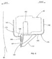
- FIG. 5 is a side view showing a support structure for the modulator according to the present invention (the arrow (LEFT) in the figure indicates the vehicle body left side, and the arrow (RIGHT) indicates the vehicle body right side), and shows that a bracket 151 is attached to an upper portion of the seat stay 41, a flat portion 165 provided in the bracket 151 is provided with mount holes 166 ⁇ ( ⁇ indicates plurality, here and hereafter), a cushion rubber 167 is fitted in each of the mount holes 166 ⁇ , a washer 168 is abutted on the lower surface of each of the cushion rubbers 167 ⁇ ⁇ ⁇ , a bolt 171 is made to penetrate through the washer 168 and the cushion rubber 167, and the bolts 171 ⁇ are each screw-engaged into female screw 172 provided in the modulator 68, whereby the modulator 68 is mounted to and elastically supported on the bracket 151.
- the arrow (LEFT) in the figure indicates the vehicle body left side
- the arrow (RIGHT) indicates the vehicle body right side
- FIG. 6 is a back elevation showing the bracket for supporting the modulator according to the present invention, and shows that a lateral side of the modulator 68 and the bracket 151 is covered with a side cover 82.
- the bracket 151 is comprised of a bracket main body 175 provided with the above-mentioned flat portion 165, a crank-shaped plate 176 attached to a lower side surface of the bracket main body 175, and a reinforcing plate 177 inclinedly attached to a lower portion of the bracket main body 175 for the purpose of reinforcing the bracket main body 175.
- the bracket main body 175 includes the flat portion 165, a lower vertical portion 181 bent substantially vertically downwards from the left end of the flat portion 165, a right plate portion 182 bent substantially vertically upwards from the right end of the flat portion 165, and a front plate portion 183 bent substantially vertically upwards from the front end of the flat portion 165.
- the crank-shaped plate 176 includes a vertical mount portion 185 mounted to the lower vertical portion 181 of the bracket main body 175, a horizontal portion 186 extended substantially horizontally from the upper end of the vertical mount portion 185, and a left plate portion 187 extended substantially vertically upwards from the left end of the horizontal portion 186.
- the right plate portion 182, the front plate portion 183 and the left plate portion 187 mentioned above are disposed to front on and in the vicinity of the right side surface, the front surface and the left side surface of the modulator 68.
- FIG. 7 is a plan view showing an essential part of a vehicle body rear portion showing the layout of the modulator according to the present invention, and shows that the modulator 68 (the portion outlined with bold solid line) is disposed so as to substantially overlap the seat rail 36 and the seat stay 41, and the battery 84 (the portion outlined mostly with bold broken line) is disposed so as to substantially overlap the seat rail 37 and the seat stay 42, whereby the modulator 68 and the battery 84 do not overlap the rear wheel 22.
- the modulator 68 the portion outlined with bold solid line
- the battery 84 the portion outlined mostly with bold broken line
- the two heavy component parts can be disposed with a good balance, and since the modulator 68 and the battery 84 do not overlap the rear wheel 22, the amount of upward movement of the rear wheel 22 can be enlarged.
- the modulator 68 includes the above-mentioned controller 116 disposed on the outside in the vehicle width direction, and a pump-motor unit 191 disposed on the inside in the vehicle width direction relative to the controller 116.
- the pump-motor unit 191 is a portion containing therein the above-mentioned pumps 127, 128 (see FIG. 3), a motor 131 (see FIG. 3) and the like.
- the circular mark 192 indicated by two-dotted chain line in the figure is a central portion of the modulator 68 in plan view, and also is the position of the center of gravity in this example. Even in the case where the central portion and the center of gravity differ from each other, it naturally suffices that either one of them is disposed on the lower side of the seat rail 36.
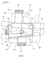
- FIG. 8 is a plan view for illustrating the bracket for supporting the modulator according to the present invention, and shows that the bracket 151 is provided with the right plate portion 182, the front plate portion 183 and the left plate portion 187, the right side surface 68a, the front surface 68b and the left side surface 68c of the modulator 68 are supported by the right plate portion 182, the front plate portion 183 and the left plate portion 187 through elastic materials 194, 195 and 196, and the three mount holes 166 in the bracket 151 are arranged at the vertexes of a triangle.
- a plate portion for supporting the modulator 68 is not provided at a rear portion of the bracket 151, since the modulator 68 is to be mounted to the bracket 151 from the rear side.
- the mount holes 166 are arranged at the vertexes of a triangle, so as to ensure that the modulator 68 is securely supported by the bracket 151 in both the front-rear direction of the vehicle and the left-right direction of the vehicle.
- symbol 198 denotes a harness for supplying the controller 116 with various signals or for sending various signals from the controller 116 to other component part
- symbol 201 denotes a connector for connecting the harness 198 to the controller 116
- symbol 199 denotes a coupler portion provided at a rear portion of the controller 116 for connecting the connector 201.
- FIG. 9 is a first functional view for illustrating the function of the layout of the modulator according to the present invention.
- a circular mark 192 which indicates a central portion, or a portion including the center of gravity, of the modulator 68.
- a vertical straight line 203 passing through the center of the circular mark 192 is spaced by a distance L to the inner side in the vehicle width direction from a vertical straight line 204 passing through the center of the seat stay 41.
- the pump unit is disposed on the inner side relative to a seat stay disposed substantially on the lower side of the seat rail.
- the rigidity of the bracket 151 can be set lower, and it is possible to contrive decreases in weight and size of the bracket 151.
- FIG. 10 is a second functional view for illustrating the function of the layout of the modulator according to the present invention.
- the modulator 68 is mounted through the bracket 151 to an upper portion of the seat stay 41 inclined rearwardly upwards, i.e., is disposed on the upper side of the seat stay 41. Therefore, even when a flying stone 206 comes from the rear side of the vehicle, the lower side of the vehicle or the rear lower side of the vehicle toward the modulator 68, the flying stone 206 is blocked by the seat stay 41, so that collision of the flying stone 206 against the modulator 68 can be prevented.
- the present invention is firstly characterized in that, in the motorcycle 10 including the vehicle body frame 11 of which a rear portion is composed of the left-right pair of seat rails 36, 37 extended substantially horizontally rearwards, the rear ends of the seat rails 36, 37 being supported by the rear ends of the left-right pair of seat stays 41, 42 extended rearwardly upwards, and the modulator 68 for controlling the brake forces for the front wheel 14 and the rear wheel 22, the modulator 68 being disposed in the vicinity of the seat rail 36 and the seat stay 41, the modulator 68 is disposed at such a position that the portion of the circular mark 192 as the central portion thereof substantially overlaps one of the left and right seat rails 36 and 37 in plan view and on the lower side of the seat rail 36.
- the modulator 68 disposed so as to substantially overlap the seat rail 36, it is ensured that the rear wheel 22 does not interfere with the modulator 68 even when moved upwards, and the amount of upward movement of the rear wheel 22 can be enlarged. Therefore, in the case of an off-road vehicle, for example, the bad road running performance can be enhanced.
- the present invention is secondly characterized in that the modulator 68 is supported on the side of the seat stay 41 and is disposed on the upper side of the seat stay 41, as has been described referring to FIGS. 4, 9 and 10.
- the present invention is thirdly characterized in that the modulator 68 is disposed on the inner side relative to the outermost side of the side cover 82 for covering a side portion of the vehicle body, as has been described referring to FIG. 6.
- the side cover 82 first makes contact with the ground, so that the modulator 68 can be protected, and reliability can be enhanced.
- the present invention is fourthly characterized in that at least a part of the modulator 68 overlaps the side cover 82 in side view, as has been described referring to FIG. 7.
- the modulator 68 Since the modulator 68 is entirely covered with the side cover 82, the modulator 68 can be protected more securely.
- the present invention is fifthly characterized in that the battery 84 is disposed on the lower side of the other seat rail 37 opposite to the one seat rail 36 located on the side of the modulator 68, as has been described referring to FIGS. 4 and 7.
- the present invention is sixthly characterized in that the modulator 68 is held by the bracket 151 fixed to the seat stay 41, and the bracket 151 is provided with the front plate portion 183, the left plate portion 187, and the right plate portion 182 as holding walls for respectively holding the front surface 68b as a front portion and the left side surface 68c and the right side surface 68a as left and right portions of the modulator 68, as has been described referring to FIGS. 4 and 8.
- the modulator 68 can be mounted and dismounted via the rear side of the bracket 151.
- the present invention is seventhly characterized in that the modulator 68 is composed of the pump-motor unit 191 and the controller 116 as a control unit, and the controller 116 is disposed on the outside of the vehicle body relative to the pump-motor unit 191, as has been described referring to FIG. 7.
- the pump-motor portion 191 which is a heavy component part can be disposed near the vehicle body center side, and concentration of mass to the vehicle body center side can be contrived.
- the present invention is eighthly characterized in that the controller 116 is provided with the coupler portion 199 to be connected to the harness 198 on the vehicle body side, and the coupler portion 199 is provided at a rear portion of the controller 116 on the rear side relative to the pump-motor unit 191, as has been described referring to FIGS. 4 and 8.
- the coupler portion 199 With the coupler portion 199 provided on the rear side relative to the pump-motor unit 191 and at a rear portion of the controller 116, the coupler portion 199 can be protected with the seat stay 41, there is no need for a protective member for exclusive use for the coupler portion, and cost can be suppressed.
- the brake force control system according to the present invention is suitable for application to ABS for motorcycles and three-wheel vehicles.
- a motorcycle including a vehicle body frame 11 of which a rear portion is composed of a left-right pair of seat rails 36, 37 extended substantially horizontally rearwards, the rear ends of the seat rails 36, 37 being supported by the rear ends of a left-right pair of seat stays 41, 42 extended rearwardly upwards, and a modulator 68 for controlling brake forces for a front wheel and a rear wheel 22, the modulator 68 being disposed in the vicinity of the seat rail 36 and the seat stay 41, the modulator 68 is disposed at such a position that a central portion thereof or a portion of the circular mark 192 as the center of gravity thereof substantially overlaps the seat rail 36 on one side in plan view and on the lower side of the seat rail 36.
Landscapes
- Engineering & Computer Science (AREA)
- Mechanical Engineering (AREA)
- Physics & Mathematics (AREA)
- Transportation (AREA)
- Electromagnetism (AREA)
- Fluid Mechanics (AREA)
- Regulating Braking Force (AREA)
Abstract
Description
- The present invention relates to a brake force control system for a motorcycle.
- As a conventional brake force control system for a motorcycle, one disposed between left and right seat rails has been known (see e.g. JP Patent no. 30 94 736).
- FIG. 2 of JP 30 94 736 will be described referring to FIG. 11, and FIG. 3 of JP 30 94 736 will be described referring to FIG. 12. Incidentally, symbols have been renewed. Besides, as to FIG. 3 of JP 3094736, only the right half of the figure is shown.
- FIG. 11 is a side view of a motorcycle including a conventional brake force control system. A
motorcycle 300 is a vehicle provided with avehicle body frame 314 including ahead pipe 301, left and right tank rails 302 and 303 extended rearwardly downwards from thehead pipe 301, a left-right pair ofseat rails seat rails motorcycle 300, apump unit 316 constituting the brake force control system is disposed between theseat rails - FIG. 12 is a plan view showing the layout of the conventional brake force control system, showing that a
pump unit holder 321 is disposed bridgingly between the left andright seat rails pump unit 316 and abattery 322 are supported by thepump unit holder 321. Incidentally,symbols pump unit holder 321 for the purpose of mounting thepump unit holder 321 to the left andright seat rails - The
pump unit 316 is comprised of apump 327, and amotor 328 for driving thepump 327, and the brake force control system includes thepump 327, amotor 328, and a controller, a solenoid valve and the like which are not shown in the figure. - In FIGS. 11 and 12, the
pump unit 316 is disposed in the space formed between the left andright seat rails pump unit 316 and the rear wheel 231. - In addition, since the
pump unit 316 is supported by suspending it by thepump unit holder 321 between theseat rails pump unit holder 321, which may lead to increases in weight and size. - It is an object of the present invention to dispose a brake force control system for a motorcycle in such a manner that a large amount of upward movement of a rear wheel can be secured, and to contrive decreases in weight and size of a support member for supporting the brake force control system.
- The invention as set forth in
claim 1 is characterized in that, in a motorcycle including a vehicle body frame of which a rear portion of the vehicle body frame is comprised of a left-right pair of seat rails extended substantially horizontally rearwards, the rear ends of the seat rails being supported by the rear ends of a left-right pair of seat stays extended rearwardly upwards, and a brake force control system for controlling a brake force for a wheel, the brake force control system being disposed in the vicinity of the seat rail and the seat stay, the brake force control system is disposed at such a position that a central portion thereof or the center of gravity thereof substantially overlaps one of the left and right seat rails in plan view and on the lower side of the one seat rail. - The brake force control system is disposed at such a position that a central portion thereof or the center of gravity thereof substantially overlaps one of the left and right seat rails and on the lower side of the one seat rail so that a rear wheel does not interfere with the brake force control system when moved upwards.
- The invention as set forth in claim 2 is characterized in that the brake force control system is supported on the seat stay side and is disposed on the upper side of the seat stay.
- The brake force control system is supported on the seat stay side, and a central portion of the brake force control system is disposed to overlap the seat rail in plan view, so as thereby to suppress a moment acting on the seat stay side, for example, on a support member attached to the seat stay for supporting the brake force control system when a vertical force is exerted on the brake force control system.
- The invention as set forth in claim 3 is characterized in that the brake force control system is disposed on the inner side relative to the outermost side of a side cover for covering a side portion of a vehicle body.
- For example, when the motorcycle falls down, the side cover first makes contact with the ground, whereby the brake force control system is protected.
- The invention as set forth in claim 4 is characterized in that at least a part of the brake force control system overlaps the side cover in side view.
- The brake force control system is covered with the side cover, whereby the brake force control system is protected more securely.
- The invention as set forth in claim 5 is characterized in that a battery is disposed on the lower side of the other seat rail which is opposite to the one seat rail located on the side of the brake force control system.
- The brake force control system and the battery are disposed respectively near the left and right seat rails, whereby a weight balance is secured on the left and right sides of the vehicle body.
- The invention as set forth in claim 6 is characterized in that the brake force control system is held by a bracket fixed to the seat stay, and the bracket includes holding walls for respectively holding a front portion and left and right portions of the brake force control system.
- The front portion and the left and right portions of the brake force control system are held by the holding walls of the bracket, whereby it is made possible to mount and dismount the brake force control system via the rear side of the bracket.
- The invention as set forth in claim 7 is characterized in that the brake force control system includes a pump-motor unit and a control unit, and the control unit is disposed on the outside of the vehicle body relative to the pump-motor unit.
- The control unit is disposed on the outside of the vehicle body relative to the pump-motor unit, and the pump-motor unit is disposed on the inner side of the vehicle body, whereby the heavy body is located near the vehicle body center side, and concentration of mass on the vehicle body center side is contrived.
- The invention as set forth in claim 8 is characterized in that the control unit includes a coupler portion to be connected to a harness on the vehicle body side, and the coupler portion is provided on the rear side of the pump-motor unit and on the side of a rear portion of the vehicle body.
- The coupler portion is provided on the rear side of the pump-motor unit and on the side of a rear portion of the vehicle body, and is protected by the seat stay.
- In the invention as set forth in
claim 1, the brake force control system is disposed at such a position that a central portion thereof or the center of gravity thereof substantially overlaps one of the left and right seat rails in plan view and on the lower side of the one seat rail. Therefore, the rear wheel does not interfere with the brake force control system even when moved upwards, and the amount of upward movement of the rear wheel can be enlarged. Therefore, in the case of an off-road vehicle, the bad road running performance can be enhanced. - In the invention as set forth in claim 2, the brake force control system is supported on the seat rail side, and a central portion of the brake force control system overlaps the seat rail in plan view, so that it is possible to suppress the moment acting on the seat rail side, for example, on a support member mounted to the seat rail for the purpose of supporting the brake force control system when a vertical force is exerted on the brake force control system. Therefore, the rigidity of the support member can be set low, and it is possible to contrive decreases in weight and size of the support member.
- Besides, with the brake force control system disposed on the upper side of the seat rail, a flying stone and the like coming from the lower side of the brake force control system can be blocked by the seat rail, and the brake force control system can be protected.
- In the invention as set forth in claim 3, the brake force control system is disposed on the inner side relative to the outermost side of a side cover for covering side portions of the vehicle body. Therefore, when the motorcycle falls down, for example, the side cover first makes contact with the ground, so that the brake force control system can be protected, and reliability can be enhanced.
- In the invention as set forth in claim 4, at least a part of the brake force control system overlaps the side cover in side view, so that the brake force control system is covered with the side cover and, therefore, the brake force control system can be protected more securely.
- In the invention as set forth in claim 5, the battery is disposed on the lower side of the other seat rail opposite to the one seat rail located on the side of the brake force control system, so that a good weight balance is obtained on the left and right sides of the vehicle body.
- In the invention as set forth in claim 6, the front portion and the left and right portions of the brake force control system are held by the holding walls of the bracket, so that the brake force control system can be mounted and dismounted via the rear side of the bracket.
- In the invention as set forth in claim 7, the control unit is disposed on the outside of the vehicle body relative to the pump-motor unit, and the pump-motor unit is disposed on the inner side of the vehicle body, so that the pump-motor unit as a heavy body can be disposed near the vehicle body center side, and concentration of mass on the vehicle body center side can be contrived.
- In the invention as set forth in claim 8, the coupler portion is provided on the rear side of the pump-motor unit and on the side of a rear portion of the vehicle body, so that the coupler portion can be protected by the seat stay, there is no need for a protective member for exclusive use for the coupler portion, and a reduction in cost can be achieved.
- The best mode for carrying out the present invention will be described below based on the accompanying drawings. Incidentally, the drawings are to be looked at according to the posture of symbols.
- FIG. 1 is a side view of a motorcycle comprising a brake force control system according to the present invention.
- FIG. 2 is a diagram showing the configuration of a brake device according to the present invention.
- FIG. 3 is a diagram showing in detail the configuration of the brake device according to the present invention.
- FIG. 4 is a side view of an essential part of a vehicle body rear portion showing the layout of a modulator according to the present invention.
- FIG. 5 is a side view showing a support structure for the modulator according to the present invention.
- FIG. 6 is a back elevation showing a bracket according to the present invention.
- FIG. 7 is a plan view of an essential part of a vehicle body rear portion showing the layout of the modulator according to the present invention.
- FIG. 8 is a plan view for illustrating the bracket for supporting the modulator according to the present invention.
- FIG. 9 is a first functional view showing the function of the layout of the modulator according to the present invention.
- FIG. 10 is a second functional view showing the function of the layout of the modulator according to the present invention.
- FIG. 11 is a side view of a motorcycle comprising a conventional brake force control system.
- FIG. 12 is a plan view showing the layout of the conventional brake force control system.
-
- FIG. 1 is a side view of a motorcycle including a brake force control system according to the present invention. The
motorcycle 10 is a vehicle in which afront fork 13 is steerably mounted to ahead pipe 12 provided at the front end of avehicle body frame 11, afront wheel 14 is mounted to lower portions of thefront fork 13, asteering bar handle 16 is attached to an upper portion of thefront fork 13, anengine 17 and atransmission 18 integrally connected to theengine 17 are mounted on the inside of thevehicle body frame 11, aswing arm 21 is vertically swingably mounted to a lower portion of thevehicle body frame 11, and arear wheel 22 is mounted to the rear end of theswing arm 21. In addition, an anti-lock brake system (ABS) described below is mounted on the vehicle for the purpose of preventing thefront wheel 14 and therear wheel 22 from being locked at the time of braking. - The
vehicle body frame 11 is comprised of left and rightmain frames 31 and 32 (onlysymbol 32 on the viewer's side is shown) extended rearwardly downwards from thehead pipe 12, left and right down frames 33 and 34 (onlysymbol 34 on the viewer's side is shown) extended substantially downwards from thehead pipe 12 and then rearwards and connected respectively to the lower ends of themain frames seat rails 36 and 37 (onlysymbol 37 on the viewer's side is shown) extended substantially horizontally rearwards from bent portions of themain frames symbol 42 on the viewer's side is shown) extended rearwardly upwards from respective lower portions of themain frames seat rails symbol 44 on the viewer's side is shown) denote reinforcing frames disposed bridgingly between themain frames down frames 33, 34. - The
front wheel 14 is fitted with abrake disk 47. A frontwheel disk brake 51 is constituted of thebrake disk 47, and abrake caliper 48 attached to thefront fork 13 for the purpose of braking by clamping thebrake disk 47. - The
rear wheel 22 is fitted with abrake disk 53. A rearwheel disk brake 55 is constituted of thebrake disk 53, and abrake caliper 54 attached to theswing arm 21 through a bracket for the purpose of braking by clamping thebrake disk 53. - The steering bar handle 16 is a component part fitted with a
throttle grip 57 for regulating the opening of a throttle provided in an intake system of theengine 17, a frontwheel brake lever 58 for braking thefront wheel 14, and afirst master cylinder 61 for generating a brake liquid pressure when the frontwheel brake lever 58 is operated. -
Symbol 63 denotes a rear wheel brake pedal for braking therear wheel 22. Abracket 64 is attached to a lower portion of themain frame 32, and the rearwheel brake pedal 63 is mounted to thebracket 64. -
Symbol 66 denotes a second master cylinder for generating a brake liquid pressure when the rearwheel brake pedal 63 is operated. -
Symbol 68 denotes a modulator as the brake force control system constituting the ABS, for preventing the locking of thefront wheel 14 and therear wheel 22 by regulating the brake forces acting on thefront wheel 14 and therear wheel 22. - Here,
symbol 75 denotes a front fender for covering the upper side of thefront wheel 14,symbol 76 denotes a front cowl for covering a front portion of the vehicle body,symbol 77 denotes a fuel tank attached to upper portions of themain frames symbol 78 denotes a seat attached to upper portions of the seat rails 36, 37,symbol 81 denotes an engine guard for covering the front side of theengine 17,symbols 82 and 83 (onlysymbol 83 on one side is shown) denote side covers for covering the lateral sides of the space between the seat rails 36, 37 and the seat stays 41, 42 on the lower side of theseat 78,symbol 84 denotes a battery,symbol 86 denotes a muffler,symbol 87 denotes a rear fender for covering the upper side of therear wheel 22, andsymbol 88 denotes a tail lamp. - FIG. 2 is a diagram showing the configuration of a brake device according to the present invention. The brake device 90 is comprised of the above-mentioned front wheel brake lever 58, the first master cylinder 61, the rear wheel brake pedal 63, the second master cylinder 66, the modulator 68 connected to the first master cylinder 61 and the second master cylinder 66 through pipings 91 and 92 respectively, the front disk brakes 51, 51 (specifically, brake calipers 48, 48) connected to the modulator 68 through pipings 93 to 98, the rear wheel disk brakes 55 (specifically, a brake caliper 54) connected to the modulator 68 via a pressure control valve (PCV) 101 for controlling the brake liquid pressure and through pipings 102 to 104, a delay valve (DV) 106 provided at an intermediate portion of a piping 105 for connecting the front wheel disk brake 51 on one side (specifically, the brake caliper 48 on one side) and the modulator 68 for the purpose of distributing the brake liquid pressure also to the front wheel disk brake 51 and delaying the supply of the liquid pressure to the side of the front wheel disk brake 51 relative to the side of the rear wheel disk brake 55 when the rear wheel brake pedal 63 is operated, a front wheel speed sensor 108 connected to the modulator 68 through a piping 107 for the purpose of detecting the rotating speed (namely, wheel speed) of the front wheel 14, and a rear wheel speed sensor 111 connected to the modulator 68 through a piping 109 for the purpose of detecting the rotating speed of the rear wheel 22.
- Here,
symbols brake caliper 48 for the purpose of movably containing therein a piston for generating a pressing force for clamping thebrake disk 47, andsymbols brake caliper 54 for the purpose of containing therein a piston for generating a pressing force for clamping thebrake disk 53. In addition, in the figure, the pipings for the brake liquid are indicated by bold lines, while conductors are indicated by thin lines (this applies here and hereafter) . - FIG. 3 is a diagram showing in detail the brake device according to the present invention, in which the
modulator 68 as the brake force control system of the present invention includes an ABSliquid pressure controller 115 and acontrol unit 116 for controlling the ABSliquid pressure controller 115. - The ABS
liquid pressure controller 115 includes front wheelside solenoid valves side solenoid valves motor 131 for driving thepumps reservoirs check valves - The front wheel
side solenoid valve 121 and the rearwheel solenoid valve 123 are valves which are kept open at the time of a normal braking operation conducted by operating the frontwheel brake lever 58 and the rearwheel brake pedal 63 without operating the ABS. - The front
wheel solenoid valve 122 and the rearwheel solenoid valve 124 are valves which are kept closed at the time of the normal braking operation conducted by operating the frontwheel brake lever 58 and the rearwheel brake pedal 63 without operating the ABS. - The
controller 116 is a device for controlling the operations of thesolenoid valves 121 to 124 and themotor 131. - The front
wheel speed sensor 108 and the rearwheel speed sensor 111 are, for example, electromagnetic induction type sensors. - The
modulator 68, the frontwheel speed sensor 108 and the rearwheel speed sensor 111 constitute theABS 138. - The
ABS 138 is a device for preventing the wheel locking which might occur at the time of rapid braking or at the time of braking on a slippery road surface. - FIG. 4 is a side view of an essential part of a vehicle body rear portion showing the layout of the modulator according to the present invention (the arrow (FRONT) in the figure indicates the front side of the vehicle, here and hereinafter), and shows that the modulator 68 (the portion outlined with bold solid line) is mounted through a
bracket 151 to the seat stay 41 on the vehicle body left side of the left-right pair of seat stays 41 and 42 (forsymbol 42, see FIG. 1), and themodulator 68 is disposed on the lower side of theseat rail 36 on the vehicle body right side of the left-right pair of seat rails 36 and 37 (forsymbol 37, see FIG. 1). - In addition, it is shown that a
battery case 152 is mounted to theseat rail 37 on the vehicle body right side, the seat stay 42 on the vehicle body right side, the main frame 32 (see FIG. 1) and a frame (not shown), and a battery 84 (the portion outlined with bold broken line) is contained in thebattery case 152. Incidentally,symbols 154 to 156 denote support portions provided on the side of thevehicle body frame 11 for the purpose of supporting thebattery case 152,symbols battery case 152 for the purpose of mounting thebattery case 152 to thesupport portions 154 to 156. - FIG. 5 is a side view showing a support structure for the modulator according to the present invention (the arrow (LEFT) in the figure indicates the vehicle body left side, and the arrow (RIGHT) indicates the vehicle body right side), and shows that a
bracket 151 is attached to an upper portion of theseat stay 41, aflat portion 165 provided in thebracket 151 is provided withmount holes 166 ··· (··· indicates plurality, here and hereafter), acushion rubber 167 is fitted in each of the mount holes 166 ···, awasher 168 is abutted on the lower surface of each of the cushion rubbers 167· · ·, abolt 171 is made to penetrate through thewasher 168 and thecushion rubber 167, and thebolts 171 ··· are each screw-engaged intofemale screw 172 provided in themodulator 68, whereby themodulator 68 is mounted to and elastically supported on thebracket 151. - FIG. 6 is a back elevation showing the bracket for supporting the modulator according to the present invention, and shows that a lateral side of the
modulator 68 and thebracket 151 is covered with aside cover 82. - The
bracket 151 is comprised of a bracketmain body 175 provided with the above-mentionedflat portion 165, a crank-shapedplate 176 attached to a lower side surface of the bracketmain body 175, and a reinforcingplate 177 inclinedly attached to a lower portion of the bracketmain body 175 for the purpose of reinforcing the bracketmain body 175. - The bracket
main body 175 includes theflat portion 165, a lowervertical portion 181 bent substantially vertically downwards from the left end of theflat portion 165, aright plate portion 182 bent substantially vertically upwards from the right end of theflat portion 165, and afront plate portion 183 bent substantially vertically upwards from the front end of theflat portion 165. - The crank-shaped
plate 176 includes avertical mount portion 185 mounted to the lowervertical portion 181 of the bracketmain body 175, ahorizontal portion 186 extended substantially horizontally from the upper end of thevertical mount portion 185, and aleft plate portion 187 extended substantially vertically upwards from the left end of thehorizontal portion 186. - The
right plate portion 182, thefront plate portion 183 and theleft plate portion 187 mentioned above are disposed to front on and in the vicinity of the right side surface, the front surface and the left side surface of themodulator 68. - FIG. 7 is a plan view showing an essential part of a vehicle body rear portion showing the layout of the modulator according to the present invention, and shows that the modulator 68 (the portion outlined with bold solid line) is disposed so as to substantially overlap the
seat rail 36 and theseat stay 41, and the battery 84 (the portion outlined mostly with bold broken line) is disposed so as to substantially overlap theseat rail 37 and theseat stay 42, whereby themodulator 68 and thebattery 84 do not overlap therear wheel 22. - With the
modulator 68 and thebattery 84 thus disposed on the left and right sides of thevehicle body frame 11, the two heavy component parts can be disposed with a good balance, and since themodulator 68 and thebattery 84 do not overlap therear wheel 22, the amount of upward movement of therear wheel 22 can be enlarged. - The
modulator 68 includes the above-mentionedcontroller 116 disposed on the outside in the vehicle width direction, and a pump-motor unit 191 disposed on the inside in the vehicle width direction relative to thecontroller 116. - The pump-
motor unit 191 is a portion containing therein the above-mentionedpumps 127, 128 (see FIG. 3), a motor 131 (see FIG. 3) and the like. Thecircular mark 192 indicated by two-dotted chain line in the figure is a central portion of themodulator 68 in plan view, and also is the position of the center of gravity in this example. Even in the case where the central portion and the center of gravity differ from each other, it naturally suffices that either one of them is disposed on the lower side of theseat rail 36. - FIG. 8 is a plan view for illustrating the bracket for supporting the modulator according to the present invention, and shows that the
bracket 151 is provided with theright plate portion 182, thefront plate portion 183 and theleft plate portion 187, theright side surface 68a, thefront surface 68b and theleft side surface 68c of themodulator 68 are supported by theright plate portion 182, thefront plate portion 183 and theleft plate portion 187 throughelastic materials mount holes 166 in thebracket 151 are arranged at the vertexes of a triangle. - A plate portion for supporting the
modulator 68 is not provided at a rear portion of thebracket 151, since themodulator 68 is to be mounted to thebracket 151 from the rear side. - The mount holes 166 are arranged at the vertexes of a triangle, so as to ensure that the
modulator 68 is securely supported by thebracket 151 in both the front-rear direction of the vehicle and the left-right direction of the vehicle. - Here,
symbol 198 denotes a harness for supplying thecontroller 116 with various signals or for sending various signals from thecontroller 116 to other component part,symbol 201 denotes a connector for connecting theharness 198 to thecontroller 116, andsymbol 199 denotes a coupler portion provided at a rear portion of thecontroller 116 for connecting theconnector 201. - Functions relating to the layout of the
modulator 68 as above-mentioned will be described below. - FIG. 9 is a first functional view for illustrating the function of the layout of the modulator according to the present invention.
- In the figure, there is shown a
circular mark 192 which indicates a central portion, or a portion including the center of gravity, of themodulator 68. - A vertical
straight line 203 passing through the center of thecircular mark 192 is spaced by a distance L to the inner side in the vehicle width direction from a verticalstraight line 204 passing through the center of theseat stay 41. - In a system in which an ABS pump unit is disposed between left and right seat rails as in the prior art, the pump unit is disposed on the inner side relative to a seat stay disposed substantially on the lower side of the seat rail.
- In the present invention, the above-mentioned distance L is set small, whereby the
modulator 68 can be disposed substantially on the upper side of theseat stay 41, and, where the weight W of themodulator 68 and an external force F at the time of vertical movement or vertical vibration of the vehicle are exerted on thecircular mark 192, the moment M (= (W+F) X L) acting on thebracket 151 can be reduced, as compared with that in the prior art. - Therefore, the rigidity of the
bracket 151 can be set lower, and it is possible to contrive decreases in weight and size of thebracket 151. - FIG. 10 is a second functional view for illustrating the function of the layout of the modulator according to the present invention.
- The
modulator 68 is mounted through thebracket 151 to an upper portion of the seat stay 41 inclined rearwardly upwards, i.e., is disposed on the upper side of theseat stay 41. Therefore, even when a flyingstone 206 comes from the rear side of the vehicle, the lower side of the vehicle or the rear lower side of the vehicle toward themodulator 68, the flyingstone 206 is blocked by theseat stay 41, so that collision of the flyingstone 206 against themodulator 68 can be prevented. - As has been described above referring to FIGS. 1 and 7, the present invention is firstly characterized in that, in the
motorcycle 10 including thevehicle body frame 11 of which a rear portion is composed of the left-right pair of seat rails 36, 37 extended substantially horizontally rearwards, the rear ends of the seat rails 36, 37 being supported by the rear ends of the left-right pair of seat stays 41, 42 extended rearwardly upwards, and themodulator 68 for controlling the brake forces for thefront wheel 14 and therear wheel 22, themodulator 68 being disposed in the vicinity of theseat rail 36 and theseat stay 41, themodulator 68 is disposed at such a position that the portion of thecircular mark 192 as the central portion thereof substantially overlaps one of the left and right seat rails 36 and 37 in plan view and on the lower side of theseat rail 36. - With the
modulator 68 disposed so as to substantially overlap theseat rail 36, it is ensured that therear wheel 22 does not interfere with themodulator 68 even when moved upwards, and the amount of upward movement of therear wheel 22 can be enlarged. Therefore, in the case of an off-road vehicle, for example, the bad road running performance can be enhanced. - The present invention is secondly characterized in that the
modulator 68 is supported on the side of theseat stay 41 and is disposed on the upper side of theseat stay 41, as has been described referring to FIGS. 4, 9 and 10. - It is possible to suppress the moment acting on the side of the
seat stay 41, for example, on thebracket 151 as a support member attached to theseat stay 41 for the purpose of supporting themodulator 68 when a vertical force acts on themodulator 68. - In addition, with the
modulator 68 disposed on the upper side of theseat stay 41, a flyingstone 206 and the like coming from the lower side of themodulator 68 can be blocked by theseat stay 41, so that themodulator 68 can be protected. - The present invention is thirdly characterized in that the
modulator 68 is disposed on the inner side relative to the outermost side of theside cover 82 for covering a side portion of the vehicle body, as has been described referring to FIG. 6. - For example, in the case where the motorcycle 10 (see FIG. 1) falls down, the
side cover 82 first makes contact with the ground, so that themodulator 68 can be protected, and reliability can be enhanced. - The present invention is fourthly characterized in that at least a part of the
modulator 68 overlaps theside cover 82 in side view, as has been described referring to FIG. 7. - Since the
modulator 68 is entirely covered with theside cover 82, themodulator 68 can be protected more securely. - The present invention is fifthly characterized in that the
battery 84 is disposed on the lower side of theother seat rail 37 opposite to the oneseat rail 36 located on the side of themodulator 68, as has been described referring to FIGS. 4 and 7. - With the
modulator 68 and thebattery 84 disposed respectively on the lower side of the left and right seat rails 36 and 37, it is possible to obtain a good weight balance on the left and right sides of the vehicle body. - The present invention is sixthly characterized in that the
modulator 68 is held by thebracket 151 fixed to theseat stay 41, and thebracket 151 is provided with thefront plate portion 183, theleft plate portion 187, and theright plate portion 182 as holding walls for respectively holding thefront surface 68b as a front portion and theleft side surface 68c and theright side surface 68a as left and right portions of themodulator 68, as has been described referring to FIGS. 4 and 8. - Since the
front surface 68b, theleft side surface 68c, and theright side surface 68a of themodulator 68 are held by the holdingwalls bracket 151, themodulator 68 can be mounted and dismounted via the rear side of thebracket 151. - The present invention is seventhly characterized in that the
modulator 68 is composed of the pump-motor unit 191 and thecontroller 116 as a control unit, and thecontroller 116 is disposed on the outside of the vehicle body relative to the pump-motor unit 191, as has been described referring to FIG. 7. - Since the
controller 116 is disposed on the outside of the vehicle body relative to the pump-motor unit 191 and the pump-motor unit 191 is disposed on the inner side of the vehicle body, the pump-motor portion 191 which is a heavy component part can be disposed near the vehicle body center side, and concentration of mass to the vehicle body center side can be contrived. - The present invention is eighthly characterized in that the
controller 116 is provided with thecoupler portion 199 to be connected to theharness 198 on the vehicle body side, and thecoupler portion 199 is provided at a rear portion of thecontroller 116 on the rear side relative to the pump-motor unit 191, as has been described referring to FIGS. 4 and 8. - With the
coupler portion 199 provided on the rear side relative to the pump-motor unit 191 and at a rear portion of thecontroller 116, thecoupler portion 199 can be protected with theseat stay 41, there is no need for a protective member for exclusive use for the coupler portion, and cost can be suppressed. - The brake force control system according to the present invention is suitable for application to ABS for motorcycles and three-wheel vehicles.
- In relation to a brake force control system for a motorcycle, to make it possible to secure a large amount of upward movement of a rear wheel, and to contrive decreases in weight and size of a support member for supporting the brake force control system.
- In a motorcycle including a
vehicle body frame 11 of which a rear portion is composed of a left-right pair of seat rails 36, 37 extended substantially horizontally rearwards, the rear ends of the seat rails 36, 37 being supported by the rear ends of a left-right pair of seat stays 41, 42 extended rearwardly upwards, and amodulator 68 for controlling brake forces for a front wheel and arear wheel 22, themodulator 68 being disposed in the vicinity of theseat rail 36 and theseat stay 41, themodulator 68 is disposed at such a position that a central portion thereof or a portion of thecircular mark 192 as the center of gravity thereof substantially overlaps theseat rail 36 on one side in plan view and on the lower side of theseat rail 36.
Claims (8)
- A brake force control system for a motorcycle comprising a vehicle frame (11) of which a rear portion is comprised of a left-right pair of seat rails (36, 37) extended substantially horizontally rearwards, the rear ends of said seat rails (36, 37) being supported by the rear ends of a left-right pair of seat stays (41, 42) extended rearwardly upwards, and said brake force control system (68) for controlling a brake force for a wheel (22), said brake force control system (68) being disposed in the vicinity of said seat rail (36) and said seat stay (41) wherein
said brake force control system (68) is disposed at such a position that a central portion (192) thereof or the center of gravity thereof substantially overlaps one (36) of said left and right seat rails in plan view and on the lower side of said one seat rail (36). - The brake force control system for a motorcycle as set forth in claim 1, wherein said brake force control system (68) is supported on the seat stay side and on the upper side of said seat stay (41).
- The brake force control system for a motorcycle as set forth in claim 1 or 2, wherein said brake force control system (68) is disposed on the inner side relative to the outermost side of the side cover (82) for covering a side portion of a vehicle body.
- The brake force control system for a motorcycle as set forth in claim 3, wherein at least a part of said brake force control system (68) overlaps said side cover (82) in side view.
- The brake force control system for a motorcycle as set forth in any of claims 1 or 4, wherein a battery (84) is disposed on the lower side of the outer seat rail (37) which is opposite to the one seat rail (36) located on the side of said brake force control system (68).
- The brake force control system for a motorcycle as set forth in claim 2, wherein said brake force control system (68) is held by a bracket (151) fixed to said seat rail (36), and said bracket (151) comprises holding walls (182, 183, 187) for respectively holding a front portion and left and right portions of said brake force control system (68).
- The brake force control system for a motorcycle as set forth in claim 2, wherein said brake force control system (68) is comprised of a pump-motor unit (191) and a control unit (116), and said control unit (116) is disposed on the outside of a vehicle body.
- The brake force control system for a motorcycle as set forth in claim 7, wherein said control unit (116) comprises a coupler portion (199) to be connected to a harness (198) on the vehicle body side, and said coupler portion (199) is provided on the side of a rear portion of said vehicle body on the rear side of said pump-motor unit (191).
Applications Claiming Priority (2)
| Application Number | Priority Date | Filing Date | Title |
|---|---|---|---|
| JP2003386792A JP4354784B2 (en) | 2003-11-17 | 2003-11-17 | Motorcycle braking force adjusting device |
| JP2003386792 | 2003-11-17 |
Publications (2)
| Publication Number | Publication Date |
|---|---|
| EP1531104A1 true EP1531104A1 (en) | 2005-05-18 |
| EP1531104B1 EP1531104B1 (en) | 2012-06-20 |
Family
ID=34431523
Family Applications (1)
| Application Number | Title | Priority Date | Filing Date |
|---|---|---|---|
| EP20040026700 Expired - Fee Related EP1531104B1 (en) | 2003-11-17 | 2004-11-10 | Brake force control system for motorcycle |
Country Status (2)
| Country | Link |
|---|---|
| EP (1) | EP1531104B1 (en) |
| JP (1) | JP4354784B2 (en) |
Cited By (11)
| Publication number | Priority date | Publication date | Assignee | Title |
|---|---|---|---|---|
| EP1679243A1 (en) * | 2005-01-11 | 2006-07-12 | HONDA MOTOR CO., Ltd. | Arrangement structure of ABS unit for motorcycle |
| EP1792817A1 (en) * | 2005-12-01 | 2007-06-06 | HONDA MOTOR CO., Ltd. | A motorcycle |
| EP1820710A1 (en) * | 2006-02-15 | 2007-08-22 | HONDA MOTOR CO., Ltd. | Brake apparatus for two-wheeled vehicle |
| DE102009004232B4 (en) * | 2008-03-31 | 2010-12-09 | Honda Motor Co., Ltd. | Braking system for a motorcycle |
| DE102009004233B4 (en) * | 2008-03-31 | 2011-03-10 | Honda Motor Co., Ltd. | Braking system for a motorcycle |
| EP1839977A3 (en) * | 2006-03-31 | 2011-12-21 | Honda Motor Co., Ltd. | Brake system for motorcycle |
| US8146698B2 (en) | 2008-03-31 | 2012-04-03 | Honda Motor Co., Ltd. | Motorcycle including brake-by-wire system with flexibly supported pressure-generating unit |
| WO2014108234A1 (en) * | 2013-01-14 | 2014-07-17 | Robert Bosch Gmbh | Hydraulic module for an anti-lock brake system for a two-wheeler |
| US9751587B2 (en) | 2015-07-06 | 2017-09-05 | Suzuki Motor Corporation | ABS unit attachment structure and motorcycle |
| US11034405B2 (en) * | 2017-12-28 | 2021-06-15 | Honda Motor Co., Ltd. | ABS disposition structure of saddle riding vehicle |
| US11485442B2 (en) | 2017-09-28 | 2022-11-01 | Honda Motor Co., Ltd. | Straddle-type vehicle |
Families Citing this family (8)
| Publication number | Priority date | Publication date | Assignee | Title |
|---|---|---|---|---|
| JP4743535B2 (en) * | 2006-09-29 | 2011-08-10 | 本田技研工業株式会社 | Brake equipment for motorcycles |
| JP5584478B2 (en) * | 2009-04-30 | 2014-09-03 | ボッシュ株式会社 | Hydraulic unit support structure |
| CN102596700B (en) * | 2009-12-24 | 2014-02-05 | 本田技研工业株式会社 | Vehicular brake device |
| WO2011099209A1 (en) * | 2010-02-09 | 2011-08-18 | スズキ株式会社 | Scooter-type two-wheeled motor vehicle |
| JP5728352B2 (en) * | 2011-09-28 | 2015-06-03 | 本田技研工業株式会社 | Saddle riding |
| JP2013103524A (en) * | 2011-11-10 | 2013-05-30 | Honda Motor Co Ltd | Motorcycle |
| CN105722753B (en) * | 2013-11-29 | 2019-04-26 | 川崎重工业株式会社 | Motorcycle |
| JP6596756B2 (en) * | 2017-09-28 | 2019-10-30 | 本田技研工業株式会社 | Saddle riding |
Citations (3)
| Publication number | Priority date | Publication date | Assignee | Title |
|---|---|---|---|---|
| JPH0211448A (en) * | 1988-06-28 | 1990-01-16 | Kawasaki Heavy Ind Ltd | Motorcycle |
| JPH0394736A (en) | 1989-09-08 | 1991-04-19 | Tadashi Hara | Method and device for informing and alarming abnormality in physical condition |
| EP0624498A2 (en) * | 1993-05-14 | 1994-11-17 | Suzuki Kabushiki Kaisha | Antiskid braking device for motorcycle |
Family Cites Families (2)
| Publication number | Priority date | Publication date | Assignee | Title |
|---|---|---|---|---|
| JP3200770B2 (en) * | 1991-10-24 | 2001-08-20 | ヤマハ発動機株式会社 | Motorcycle |
| JP3458482B2 (en) * | 1994-10-18 | 2003-10-20 | スズキ株式会社 | ABS hydraulic unit mounting structure for motorcycle |
-
2003
- 2003-11-17 JP JP2003386792A patent/JP4354784B2/en not_active Expired - Fee Related
-
2004
- 2004-11-10 EP EP20040026700 patent/EP1531104B1/en not_active Expired - Fee Related
Patent Citations (3)
| Publication number | Priority date | Publication date | Assignee | Title |
|---|---|---|---|---|
| JPH0211448A (en) * | 1988-06-28 | 1990-01-16 | Kawasaki Heavy Ind Ltd | Motorcycle |
| JPH0394736A (en) | 1989-09-08 | 1991-04-19 | Tadashi Hara | Method and device for informing and alarming abnormality in physical condition |
| EP0624498A2 (en) * | 1993-05-14 | 1994-11-17 | Suzuki Kabushiki Kaisha | Antiskid braking device for motorcycle |
Non-Patent Citations (2)
| Title |
|---|
| PATENT ABSTRACTS OF JAPAN vol. 0141, no. 47 (M - 0952) 20 March 1990 (1990-03-20) * |
| PATENT ABSTRACTS OF JAPAN vol. 1995, no. 02 31 March 1995 (1995-03-31) * |
Cited By (17)
| Publication number | Priority date | Publication date | Assignee | Title |
|---|---|---|---|---|
| EP1679243A1 (en) * | 2005-01-11 | 2006-07-12 | HONDA MOTOR CO., Ltd. | Arrangement structure of ABS unit for motorcycle |
| EP1792817A1 (en) * | 2005-12-01 | 2007-06-06 | HONDA MOTOR CO., Ltd. | A motorcycle |
| US7617901B2 (en) | 2005-12-01 | 2009-11-17 | Honda Motor Co., Ltd. | Vehicle frame including protective cage structure for housing a fuel pump, and motorcycle incorporating same |
| EP1820710A1 (en) * | 2006-02-15 | 2007-08-22 | HONDA MOTOR CO., Ltd. | Brake apparatus for two-wheeled vehicle |
| CN101020490B (en) * | 2006-02-15 | 2010-11-10 | 本田技研工业株式会社 | Brake apparatus for two-wheeled vehicle |
| US8336968B2 (en) | 2006-02-15 | 2012-12-25 | Honda Motor Co., Ltd. | Brake apparatus for two-wheeled vehicle |
| EP1839977A3 (en) * | 2006-03-31 | 2011-12-21 | Honda Motor Co., Ltd. | Brake system for motorcycle |
| US8146697B2 (en) | 2008-03-31 | 2012-04-03 | Honda Motor Co., Ltd. | Brake system for a motorcycle, and motorcycle incorporating same |
| DE102009004233B4 (en) * | 2008-03-31 | 2011-03-10 | Honda Motor Co., Ltd. | Braking system for a motorcycle |
| US8146698B2 (en) | 2008-03-31 | 2012-04-03 | Honda Motor Co., Ltd. | Motorcycle including brake-by-wire system with flexibly supported pressure-generating unit |
| DE102009004234B4 (en) * | 2008-03-31 | 2012-10-31 | Honda Motor Co., Ltd. | motorcycle |
| DE102009004232B4 (en) * | 2008-03-31 | 2010-12-09 | Honda Motor Co., Ltd. | Braking system for a motorcycle |
| WO2014108234A1 (en) * | 2013-01-14 | 2014-07-17 | Robert Bosch Gmbh | Hydraulic module for an anti-lock brake system for a two-wheeler |
| US9751587B2 (en) | 2015-07-06 | 2017-09-05 | Suzuki Motor Corporation | ABS unit attachment structure and motorcycle |
| DE102016008228B4 (en) * | 2015-07-06 | 2017-10-19 | Suzuki Motor Corporation | Mounting structure for ABS unit and motorcycle |
| US11485442B2 (en) | 2017-09-28 | 2022-11-01 | Honda Motor Co., Ltd. | Straddle-type vehicle |
| US11034405B2 (en) * | 2017-12-28 | 2021-06-15 | Honda Motor Co., Ltd. | ABS disposition structure of saddle riding vehicle |
Also Published As
| Publication number | Publication date |
|---|---|
| JP2005145287A (en) | 2005-06-09 |
| EP1531104B1 (en) | 2012-06-20 |
| JP4354784B2 (en) | 2009-10-28 |
Similar Documents
| Publication | Publication Date | Title |
|---|---|---|
| EP1531104B1 (en) | Brake force control system for motorcycle | |
| CA2670558C (en) | Motorcycle | |
| EP1820710B1 (en) | Two-wheeled vehicle with brake apparatus | |
| EP1679243B1 (en) | Motorcycle with ABS unit | |
| JP6459859B2 (en) | Sensor support structure and motorcycle | |
| US9022157B2 (en) | Motorcycle | |
| JP6481529B2 (en) | Inertia sensor mounting structure and motorcycle | |
| US20020029940A1 (en) | Brake device | |
| JP2017013730A (en) | Structure for mounting abs unit and motorcycle | |
| EP2048051B1 (en) | Straddle-type vehicle | |
| US11203392B2 (en) | Saddle riding vehicle | |
| JP5101231B2 (en) | Saddle riding vehicle | |
| CN112543732B (en) | Saddle-ride type vehicle | |
| CN107226157B (en) | Saddle-ride type vehicle | |
| JP6610699B2 (en) | Inertial sensor mounting structure and saddle riding type vehicle | |
| JP3157690U (en) | Saddle riding vehicle | |
| JP6687085B2 (en) | Sensor support structure | |
| CN219044379U (en) | Saddle-type vehicle | |
| CN112672952B (en) | Saddle-ride type vehicle | |
| JP6927270B2 (en) | Inertia sensor mounting structure | |
| JP2019031285A (en) | Sensor support structure and motorcycle |
Legal Events
| Date | Code | Title | Description |
|---|---|---|---|
| PUAI | Public reference made under article 153(3) epc to a published international application that has entered the european phase |
Free format text: ORIGINAL CODE: 0009012 |
|
| 17P | Request for examination filed |
Effective date: 20050217 |
|
| AK | Designated contracting states |
Kind code of ref document: A1 Designated state(s): AT BE BG CH CY CZ DE DK EE ES FI FR GB GR HU IE IS IT LI LU MC NL PL PT RO SE SI SK TR |
|
| AX | Request for extension of the european patent |
Extension state: AL HR LT LV MK YU |
|
| AKX | Designation fees paid |
Designated state(s): DE IT |
|
| 17Q | First examination report despatched |
Effective date: 20051107 |
|
| REG | Reference to a national code |
Ref country code: DE Ref legal event code: R079 Ref document number: 602004038265 Country of ref document: DE Free format text: PREVIOUS MAIN CLASS: B60T0008260000 Ipc: B60T0008360000 |
|
| GRAP | Despatch of communication of intention to grant a patent |
Free format text: ORIGINAL CODE: EPIDOSNIGR1 |
|
| RIC1 | Information provided on ipc code assigned before grant |
Ipc: B60T 8/32 20060101ALI20120118BHEP Ipc: B60T 8/36 20060101AFI20120118BHEP Ipc: B62L 3/08 20060101ALI20120118BHEP |
|
| GRAS | Grant fee paid |
Free format text: ORIGINAL CODE: EPIDOSNIGR3 |
|
| GRAA | (expected) grant |
Free format text: ORIGINAL CODE: 0009210 |
|
| AK | Designated contracting states |
Kind code of ref document: B1 Designated state(s): DE IT |
|
| RIN1 | Information on inventor provided before grant (corrected) |
Inventor name: HIRANO, AKINORI C/O KABUSHIKI KAISHA HONDA GIJUTSU Inventor name: YAMAKURA, YUTAKA C/O KABUSHIKI KAISHA HONDA GIJUTS |
|
| REG | Reference to a national code |
Ref country code: DE Ref legal event code: R096 Ref document number: 602004038265 Country of ref document: DE Effective date: 20120823 |
|
| PLBE | No opposition filed within time limit |
Free format text: ORIGINAL CODE: 0009261 |
|
| STAA | Information on the status of an ep patent application or granted ep patent |
Free format text: STATUS: NO OPPOSITION FILED WITHIN TIME LIMIT |
|
| 26N | No opposition filed |
Effective date: 20130321 |
|
| REG | Reference to a national code |
Ref country code: DE Ref legal event code: R097 Ref document number: 602004038265 Country of ref document: DE Effective date: 20130321 |
|
| REG | Reference to a national code |
Ref country code: DE Ref legal event code: R084 Ref document number: 602004038265 Country of ref document: DE Effective date: 20130802 |
|
| PGFP | Annual fee paid to national office [announced via postgrant information from national office to epo] |
Ref country code: IT Payment date: 20201013 Year of fee payment: 17 Ref country code: DE Payment date: 20201028 Year of fee payment: 17 |
|
| REG | Reference to a national code |
Ref country code: DE Ref legal event code: R119 Ref document number: 602004038265 Country of ref document: DE |
|
| PG25 | Lapsed in a contracting state [announced via postgrant information from national office to epo] |
Ref country code: DE Free format text: LAPSE BECAUSE OF NON-PAYMENT OF DUE FEES Effective date: 20220601 |
|
| PG25 | Lapsed in a contracting state [announced via postgrant information from national office to epo] |
Ref country code: IT Free format text: LAPSE BECAUSE OF NON-PAYMENT OF DUE FEES Effective date: 20211110 |