EP1530995B1 - Endkappenanordnung mit einem schlauch für eine pumpe für ein filter und filter mit einer solchen endkappenanordnung - Google Patents
Endkappenanordnung mit einem schlauch für eine pumpe für ein filter und filter mit einer solchen endkappenanordnung Download PDFInfo
- Publication number
- EP1530995B1 EP1530995B1 EP04024751A EP04024751A EP1530995B1 EP 1530995 B1 EP1530995 B1 EP 1530995B1 EP 04024751 A EP04024751 A EP 04024751A EP 04024751 A EP04024751 A EP 04024751A EP 1530995 B1 EP1530995 B1 EP 1530995B1
- Authority
- EP
- European Patent Office
- Prior art keywords
- pump hose
- cap
- holder
- inlet port
- cap assembly
- Prior art date
- Legal status (The legal status is an assumption and is not a legal conclusion. Google has not performed a legal analysis and makes no representation as to the accuracy of the status listed.)
- Expired - Lifetime
Links
- 230000002572 peristaltic effect Effects 0.000 claims abstract description 12
- 239000007788 liquid Substances 0.000 claims description 30
- 238000009530 blood pressure measurement Methods 0.000 claims description 12
- 239000012528 membrane Substances 0.000 claims description 12
- 238000001631 haemodialysis Methods 0.000 claims description 6
- 230000000322 hemodialysis Effects 0.000 claims description 6
- 238000002615 hemofiltration Methods 0.000 claims description 5
- 238000001802 infusion Methods 0.000 claims description 5
- 239000008280 blood Substances 0.000 description 20
- 210000004369 blood Anatomy 0.000 description 20
- 239000012510 hollow fiber Substances 0.000 description 15
- 238000011144 upstream manufacturing Methods 0.000 description 11
- 238000011282 treatment Methods 0.000 description 9
- 239000000463 material Substances 0.000 description 8
- 238000004382 potting Methods 0.000 description 8
- 238000000502 dialysis Methods 0.000 description 7
- 238000002616 plasmapheresis Methods 0.000 description 4
- 238000006467 substitution reaction Methods 0.000 description 4
- 238000003466 welding Methods 0.000 description 4
- 230000000295 complement effect Effects 0.000 description 3
- 239000000835 fiber Substances 0.000 description 3
- 230000002093 peripheral effect Effects 0.000 description 3
- 239000000243 solution Substances 0.000 description 3
- 239000002699 waste material Substances 0.000 description 3
- HTTJABKRGRZYRN-UHFFFAOYSA-N Heparin Chemical compound OC1C(NC(=O)C)C(O)OC(COS(O)(=O)=O)C1OC1C(OS(O)(=O)=O)C(O)C(OC2C(C(OS(O)(=O)=O)C(OC3C(C(O)C(O)C(O3)C(O)=O)OS(O)(=O)=O)C(CO)O2)NS(O)(=O)=O)C(C(O)=O)O1 HTTJABKRGRZYRN-UHFFFAOYSA-N 0.000 description 2
- 238000004026 adhesive bonding Methods 0.000 description 2
- 230000036772 blood pressure Effects 0.000 description 2
- 238000010276 construction Methods 0.000 description 2
- DDRJAANPRJIHGJ-UHFFFAOYSA-N creatinine Chemical compound CN1CC(=O)NC1=N DDRJAANPRJIHGJ-UHFFFAOYSA-N 0.000 description 2
- 229960002897 heparin Drugs 0.000 description 2
- 229920000669 heparin Polymers 0.000 description 2
- 239000007924 injection Substances 0.000 description 2
- 238000002347 injection Methods 0.000 description 2
- 238000005259 measurement Methods 0.000 description 2
- 230000002503 metabolic effect Effects 0.000 description 2
- 102000004169 proteins and genes Human genes 0.000 description 2
- 108090000623 proteins and genes Proteins 0.000 description 2
- 230000002792 vascular Effects 0.000 description 2
- XLYOFNOQVPJJNP-UHFFFAOYSA-N water Substances O XLYOFNOQVPJJNP-UHFFFAOYSA-N 0.000 description 2
- FAPWRFPIFSIZLT-UHFFFAOYSA-M Sodium chloride Chemical compound [Na+].[Cl-] FAPWRFPIFSIZLT-UHFFFAOYSA-M 0.000 description 1
- XSQUKJJJFZCRTK-UHFFFAOYSA-N Urea Chemical compound NC(N)=O XSQUKJJJFZCRTK-UHFFFAOYSA-N 0.000 description 1
- 210000001124 body fluid Anatomy 0.000 description 1
- 239000004202 carbamide Substances 0.000 description 1
- 230000008878 coupling Effects 0.000 description 1
- 238000010168 coupling process Methods 0.000 description 1
- 238000005859 coupling reaction Methods 0.000 description 1
- 229940109239 creatinine Drugs 0.000 description 1
- 238000009792 diffusion process Methods 0.000 description 1
- 238000009826 distribution Methods 0.000 description 1
- 239000003978 infusion fluid Substances 0.000 description 1
- 238000004806 packaging method and process Methods 0.000 description 1
- 239000011148 porous material Substances 0.000 description 1
- 238000002360 preparation method Methods 0.000 description 1
- 230000037452 priming Effects 0.000 description 1
- 238000005086 pumping Methods 0.000 description 1
- 239000011780 sodium chloride Substances 0.000 description 1
- 239000000126 substance Substances 0.000 description 1
- 210000002105 tongue Anatomy 0.000 description 1
Images


Classifications
-
- B—PERFORMING OPERATIONS; TRANSPORTING
- B01—PHYSICAL OR CHEMICAL PROCESSES OR APPARATUS IN GENERAL
- B01D—SEPARATION
- B01D65/00—Accessories or auxiliary operations, in general, for separation processes or apparatus using semi-permeable membranes
-
- A—HUMAN NECESSITIES
- A61—MEDICAL OR VETERINARY SCIENCE; HYGIENE
- A61M—DEVICES FOR INTRODUCING MEDIA INTO, OR ONTO, THE BODY; DEVICES FOR TRANSDUCING BODY MEDIA OR FOR TAKING MEDIA FROM THE BODY; DEVICES FOR PRODUCING OR ENDING SLEEP OR STUPOR
- A61M1/00—Suction or pumping devices for medical purposes; Devices for carrying-off, for treatment of, or for carrying-over, body-liquids; Drainage systems
- A61M1/14—Dialysis systems; Artificial kidneys; Blood oxygenators ; Reciprocating systems for treatment of body fluids, e.g. single needle systems for hemofiltration or pheresis
- A61M1/16—Dialysis systems; Artificial kidneys; Blood oxygenators ; Reciprocating systems for treatment of body fluids, e.g. single needle systems for hemofiltration or pheresis with membranes
-
- A—HUMAN NECESSITIES
- A61—MEDICAL OR VETERINARY SCIENCE; HYGIENE
- A61M—DEVICES FOR INTRODUCING MEDIA INTO, OR ONTO, THE BODY; DEVICES FOR TRANSDUCING BODY MEDIA OR FOR TAKING MEDIA FROM THE BODY; DEVICES FOR PRODUCING OR ENDING SLEEP OR STUPOR
- A61M1/00—Suction or pumping devices for medical purposes; Devices for carrying-off, for treatment of, or for carrying-over, body-liquids; Drainage systems
- A61M1/36—Other treatment of blood in a by-pass of the natural circulatory system, e.g. temperature adaptation, irradiation ; Extra-corporeal blood circuits
- A61M1/3606—Arrangements for blood-volume reduction of extra-corporeal circuits
-
- A—HUMAN NECESSITIES
- A61—MEDICAL OR VETERINARY SCIENCE; HYGIENE
- A61M—DEVICES FOR INTRODUCING MEDIA INTO, OR ONTO, THE BODY; DEVICES FOR TRANSDUCING BODY MEDIA OR FOR TAKING MEDIA FROM THE BODY; DEVICES FOR PRODUCING OR ENDING SLEEP OR STUPOR
- A61M1/00—Suction or pumping devices for medical purposes; Devices for carrying-off, for treatment of, or for carrying-over, body-liquids; Drainage systems
- A61M1/36—Other treatment of blood in a by-pass of the natural circulatory system, e.g. temperature adaptation, irradiation ; Extra-corporeal blood circuits
- A61M1/3621—Extra-corporeal blood circuits
- A61M1/3627—Degassing devices; Buffer reservoirs; Drip chambers; Blood filters
-
- A—HUMAN NECESSITIES
- A61—MEDICAL OR VETERINARY SCIENCE; HYGIENE
- A61M—DEVICES FOR INTRODUCING MEDIA INTO, OR ONTO, THE BODY; DEVICES FOR TRANSDUCING BODY MEDIA OR FOR TAKING MEDIA FROM THE BODY; DEVICES FOR PRODUCING OR ENDING SLEEP OR STUPOR
- A61M60/00—Blood pumps; Devices for mechanical circulatory actuation; Balloon pumps for circulatory assistance
- A61M60/10—Location thereof with respect to the patient's body
- A61M60/104—Extracorporeal pumps, i.e. the blood being pumped outside the patient's body
- A61M60/109—Extracorporeal pumps, i.e. the blood being pumped outside the patient's body incorporated within extracorporeal blood circuits or systems
- A61M60/113—Extracorporeal pumps, i.e. the blood being pumped outside the patient's body incorporated within extracorporeal blood circuits or systems in other functional devices, e.g. dialysers or heart-lung machines
-
- A—HUMAN NECESSITIES
- A61—MEDICAL OR VETERINARY SCIENCE; HYGIENE
- A61M—DEVICES FOR INTRODUCING MEDIA INTO, OR ONTO, THE BODY; DEVICES FOR TRANSDUCING BODY MEDIA OR FOR TAKING MEDIA FROM THE BODY; DEVICES FOR PRODUCING OR ENDING SLEEP OR STUPOR
- A61M60/00—Blood pumps; Devices for mechanical circulatory actuation; Balloon pumps for circulatory assistance
- A61M60/20—Type thereof
- A61M60/247—Positive displacement blood pumps
- A61M60/253—Positive displacement blood pumps including a displacement member directly acting on the blood
- A61M60/268—Positive displacement blood pumps including a displacement member directly acting on the blood the displacement member being flexible, e.g. membranes, diaphragms or bladders
- A61M60/279—Peristaltic pumps, e.g. roller pumps
-
- A—HUMAN NECESSITIES
- A61—MEDICAL OR VETERINARY SCIENCE; HYGIENE
- A61M—DEVICES FOR INTRODUCING MEDIA INTO, OR ONTO, THE BODY; DEVICES FOR TRANSDUCING BODY MEDIA OR FOR TAKING MEDIA FROM THE BODY; DEVICES FOR PRODUCING OR ENDING SLEEP OR STUPOR
- A61M60/00—Blood pumps; Devices for mechanical circulatory actuation; Balloon pumps for circulatory assistance
- A61M60/30—Medical purposes thereof other than the enhancement of the cardiac output
- A61M60/36—Medical purposes thereof other than the enhancement of the cardiac output for specific blood treatment; for specific therapy
- A61M60/37—Haemodialysis, haemofiltration or diafiltration
-
- A—HUMAN NECESSITIES
- A61—MEDICAL OR VETERINARY SCIENCE; HYGIENE
- A61M—DEVICES FOR INTRODUCING MEDIA INTO, OR ONTO, THE BODY; DEVICES FOR TRANSDUCING BODY MEDIA OR FOR TAKING MEDIA FROM THE BODY; DEVICES FOR PRODUCING OR ENDING SLEEP OR STUPOR
- A61M60/00—Blood pumps; Devices for mechanical circulatory actuation; Balloon pumps for circulatory assistance
- A61M60/50—Details relating to control
- A61M60/508—Electronic control means, e.g. for feedback regulation
- A61M60/538—Regulation using real-time blood pump operational parameter data, e.g. motor current
-
- B—PERFORMING OPERATIONS; TRANSPORTING
- B01—PHYSICAL OR CHEMICAL PROCESSES OR APPARATUS IN GENERAL
- B01D—SEPARATION
- B01D61/00—Processes of separation using semi-permeable membranes, e.g. dialysis, osmosis or ultrafiltration; Apparatus, accessories or auxiliary operations specially adapted therefor
- B01D61/24—Dialysis ; Membrane extraction
- B01D61/30—Accessories; Auxiliary operation
-
- B—PERFORMING OPERATIONS; TRANSPORTING
- B01—PHYSICAL OR CHEMICAL PROCESSES OR APPARATUS IN GENERAL
- B01D—SEPARATION
- B01D63/00—Apparatus in general for separation processes using semi-permeable membranes
- B01D63/02—Hollow fibre modules
-
- A—HUMAN NECESSITIES
- A61—MEDICAL OR VETERINARY SCIENCE; HYGIENE
- A61M—DEVICES FOR INTRODUCING MEDIA INTO, OR ONTO, THE BODY; DEVICES FOR TRANSDUCING BODY MEDIA OR FOR TAKING MEDIA FROM THE BODY; DEVICES FOR PRODUCING OR ENDING SLEEP OR STUPOR
- A61M2205/00—General characteristics of the apparatus
- A61M2205/12—General characteristics of the apparatus with interchangeable cassettes forming partially or totally the fluid circuit
-
- B—PERFORMING OPERATIONS; TRANSPORTING
- B01—PHYSICAL OR CHEMICAL PROCESSES OR APPARATUS IN GENERAL
- B01D—SEPARATION
- B01D2313/00—Details relating to membrane modules or apparatus
- B01D2313/21—Specific headers, end caps
Definitions
- the present invention relates to an end-cap assembly for a filter, in particular, to an end-cap assembly for a hollow fiber filter.
- the invention also relates to a filter comprising such an end-cap assembly.
- a conventional hollow fiber filter comprises a tubular housing, a semi-permeable membrane in the form a bundle of hollow fibers extending within the housing and secured thereto at both ends, and two end-caps closing the housing at both ends.
- the ends of the fibers are secured to the housing by a potting material in which they are embedded.
- the potting material forms a disk that extends perpendicularly to the longitudinal axis of the housing. The ends of the fibers open on an outer surface of the disks of potting material.
- such a hollow fiber filter therefore comprises a first and the second compartments isolated from each other: the first compartment includes the interior of the hollow fibers and the space delimited at each end of the filter between the outer surface of the disk of potting material and the inner surface of the end-cap, and the second compartment includes the space outside of the hollow fibers that is delimited by the inner surface of the housing and the inner surface of the disks of potting material.
- Each end-cap comprises an inlet/outlet nozzle through which a liquid can be flown into and out of the first compartment.
- the housing is also fitted with one or two nozzle that gives access to the second compartment.
- Hollow fiber filters are used in particular in various extracorporeal treatments of blood, such as hemodialysis, hemofiltration, hemodiafiltration, plasmapheresis.
- the same type of filter usually referred to as hemodialyzer or hemofilter, is used for hemodialysis, hemofiltration, hemodiafiltration.
- the main difference between a hemodialyzer and a plasmafilter is the pore size of their respective membrane, a membrane for plasmapheresis allowing the proteins contained in blood to migrate therethough, whereas a membrane for hemodialysis does not.
- blood is withdrawn from the patient, flown through the first compartment of a hollow fiber filter, and returned to the patient.
- a dialysis liquid is simultaneously flown though the second compartment of the filter and the metabolic wastes (urea, creatinine) contained in blood migrate by diffusion through the membrane into the second compartment.
- the metabolic wastes urea, creatinine
- a pressure difference is created across the membrane so that plasma water flows through the membrane into the second compartment of the filter.
- metabolic wastes migrate by convection into the second compartment.
- the patient is simultaneously injected a sterile substitution solution.
- Hemodiafiltration is a combination of hemodialysis and hemofiltration, and, in this treatment, a dialysis liquid is flown through the second compartment and a substitution liquid is injected into the patient.
- a pressure difference is created across the membrane so that plasma (i.e. plasma water and proteins) flows through the membrane into the second compartment of the filter. Once treated, the plasma is returned to the patient.
- a machine for performing any of the above treatments comprises a peristaltic pump for withdrawing blood from the patient through a so-called “arterial line” connected at one end to the vascular circuit of the patient and at the other end to the inlet nozzle of the first compartment of a filter, for pumping blood into the filter, and for returning blood to the patient through a so-called “venous line” connected at one end to the outlet nozzle of the first compartment of the filter and at the other end to the vascular circuit of the patient.
- the machine also usually comprises a first blood pressure sensor for measuring the pressure of blood in the arterial line upstream of the pump, a second blood pressure sensor for measuring the pressure of blood in the arterial line downstream of the pump, a third pressure sensor for measuring the pressure of blood in the venous line, a bubble detector for detecting air bubbles in the venous line and a clamp for closing the venous line, for example when air bubbles are detected by the bubble detector.
- An arterial line typically comprises the following components connected together by segments of flexible tubes: a first Luer connector for connection to an arterial cannula, an arterial bubble trap, a pump hose for cooperating with the rotor of the peristaltic pump of the machine, and a second Luer connector for connection to the inlet nozzle of the first compartment of a filter.
- a venous line typically comprises the following components connected together by segments of flexible tubes: a first Luer connector for connection to the outlet nozzle of the first compartment of a filter, a venous bubble trap, and a second Luer connector for connection to a venous cannula.
- the first and third pressure sensors of the machine are connected to the arterial and venous bubble trap respectively, when the machine, the arterial line the venous line and the filter are assembled in view of a treatment.
- a dialysis machine further comprises a dialysis liquid generator that can be connected through a supply line to the inlet nozzle of the second compartment of a hemodialyzer.
- the dialysis machine also comprises a waste line by which the outlet nozzle of the hemodialyzer can be connected to the drain.
- a hollow fiber ultrafilter of similar construction as described above can be connected to the supply line so that an extra pure dialysis liquid is supplied to the hemodialyzer. The invention also applies to such an ultrafilter.
- an object of the invention is to design and end-cap assembly that facilitates such an assemblage.
- an end-cap assembly for closing one end of a housing of a filter comprises:
- inlet port means the passage through the end wall of the end-cap as well as any straight or bent nozzle or channel that may extend this passage on the outer side of the end cap.
- This arrangement facilitates the loading of a filter in a machine having a peristaltic pump for circulating a liquid in the filter.
- the inlet port and the first holder are arranged relative to each other so that the loop formed by the pump hose substantially extends in a plane that is inclined with respect to a plane perpendicular to a central axis of the end-cap.
- the inlet port and the first holder are arranged relative to each other so that the first end and second end of the pump hose are longitudinally spaced apart from each other with respect to the central axis of the end-cap and the second end of the pump hose is further apart from the end-cap than the first end of the pump hose.
- this arrangement helps degas the pump hose, in particular when a circuit including the filter is primed with a liquid (e.g. a sterile saline liquid) before the filter is used for treating blood.
- a liquid e.g. a sterile saline liquid
- the inlet port and the first holder are arranged relative to each other so that the loop formed by the pump hose substantially extends in a plane parallel to a central axis of the end-cap when the first end of the pump hose is connected to the inlet port and the second end of the pump hose is secured by the first holder.
- the first holder is removably mounted on the end-cap.
- the end-cap assembly comprises a second holder for holding the pump hose between the inlet port and the first holder.
- the end-cap assembly comprises a pump hose connected to the inlet port and the holder, e.g. by gluing or welding.
- Another object of the invention is pump hose for a peristaltic pump adapted to the end cap assembly of the invention.
- a pump hose has a first end fitted with a connecting element for connection to the inlet port and a second end fitted with a connecting element for connection to the first holder
- Still another object of the invention is a filter comprising such an end-cap assembly.
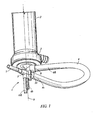
- Figure 1 shows an end-cap assembly 1 mounted at one end of a tubular housing 2 of a filter.
- the end-cap assembly 1 comprises an end-cap 3 having a slightly cambered circular end wall connected to a cylindrical peripheral wall by which the end-cap 3 is secured to the housing 2 of the filter.
- the circular end wall of the end-cap 3 is substantially perpendicular to the longitudinal axis of the housing 2, and the central axis 9 of the end-cap 3 coincides with the longitudinal axis of the housing 2.
- the end-cap assembly 1 further comprises a nozzle 8 made integral with the end-cap 3 so as to form an inlet port that gives access to the interior of the end-cap 3, and a tubular holder 5 for an end of a pump hose 4 of a peristaltic pump.
- the tubular holder 5 is secured to the nozzle 8 by welding or gluing or it can be formed integral with the nozzle 8.
- the tubular holder 5 has a larger section at one end for connection to a pump hose 4 and a smaller section at the other end for connection to a tube 7 forming the downstream part of the arterial blood line of an extracorporeal blood treatment system.
- the tubular holder 5 is so positioned with respect to the nozzle 8 as to be further apart from the end-cap 3 than the nozzle 8. It results from this arrangement that, when a first (or downstream) end 4a of a pump hose 4 is connected to the inlet port 8 and the second (or upstream) end 4b of the pump hose 4 is connected to the tubular holder 5, the first end 4a of the pump hose 4 is offset from the second end 4b along the central axis 9 of the end-cap 3.
- the end-cap assembly 1 is in an operative position, i.e. at a lower point of a filter held vertical, the tubular holder 5 and the upstream end 4b of a pump hose 4 are therefore lower than the nozzle 8 and the downstream end 4a of the pump hose 4.
- the inlet port 8 and the tubular holder 5 are so positioned with respect to each other that when a first end 4a of a pump hose 4 is connected to the inlet port 8 and the second end 4b of the pump hose 4 is connected to the tubular holder 5, the pump hose 4 forms a loop that extends in a plan that is slightly inclined with respect to a plan perpendicular to the central axis 9 of the end-cap assembly 1. Since the tubular holder 5 is lower that the nozzle 8 when the end cap assembly 1 is in an operational position, this arrangement helps gas bubbles move though the hose into the filter and prevents the stagnation of gas bubbles in the pump hose 4.
- a desired angle of inclination of the looped hose 4 with respect to a plane perpendicular to the central axis 9 of the end-cap assembly 1 may be comprised between 3 to 7 degrees, and preferably be about 5 degrees.
- the looped pump hose 4 is adapted to readily cooperate with a peristaltic pump of the rotary type upon connection of the filter to a treatment device (e.g. a dialysis machine).
- a rotary peristaltic pump comprises a rotor generally bearing two rollers at its periphery.
- the rotor is mounted in a support having a semi-circular wall that partially surrounds the rotor and defines a semi-annular gap in which the pump hose 4 can be received.
- the rollers alternately engage the pump hose 4 and squeeze it against the semicircular wall while moving along a circular path, thereby pushing the liquid contained in the pump hose 4 towards the downstream end 4a of the hose.
- the end-cap assembly 1 further comprises two Infusion/injection ports 6a, 6b connected to the tubular holder 5, which can be used for the injection of various substances (e.g. heparin or a substitution solution) to the liquid (e.g. blood) flowing through the filter.
- One of these ports can also be used as a pressure measurement port for connection to a pressure sensor for measuring the pressure of the liquid upstream of the pump hose 4.
- the end-cap assembly 1 also comprises a pressure measurement port 10 connected to the inlet port 8 for connection to a pressure sensor for measuring the pressure of the liquid entering the first compartment of the filter.
- Figures 2 to 4 show a second embodiment of the end-cap assembly 1 of the invention.
- the end-cap assembly 1 is represented without a pump hose connected thereto, whereas in Figures 4 and 5 a pump hose 4 is connected to the inlet port 8 and to the holder 5, 23.
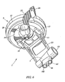
- the end-cap 3 comprises a circular end-wall portion 14 connected to a peripheral wall portion 12 that is designed for securing the end-cap 3 to the housing of a filter.
- the end-cap 3 has a central axis 9 that coincides with the longitudinal axis of the tubular housing of a filter when the end-cap is mounted at one end of such a housing.
- the circular end wall portion 14 and the peripheral wall portion 12 define an interior region 15 of the end-cap 3.
- the interior region 15 forms a header-chamber when the end-cap 3 is mounted at one end of the housing of a filter.
- the end-cap assembly 1 shown on Figures 2 to 5 has an inlet port 8 that is eccentric with respect to the central axis 9 of the end-cap 3 and is formed integral with the end-wall 14 and of the end-cap 3.
- the inlet port 8 comprises a first (upstream) portion 18 furthest to the end wall 14, a second (downstream) portion 19 closest to the end wall 14, and an intermediate portion 20 connecting the first portion 18 to the second portion 19.
- the first (upstream) portion 18 is cylindrical and has a longitudinal axis slightly inclined with respect to a plane perpendicular to the central axis 9 of the end-cap 3.
- the second (downstream) portion 19 flares towards the interior 15 of the end-cap 3 along an axis generally parallel to the central axis 9.
- the intermediate portion 20 has a curvature 16 selected so as to facilitate a smooth an unimpeded flow of a liquid pumped into the end cap 3.
- the downstream flaring portion 19 also has a curvature 17 selected so as to evenly direct a liquid pumped into the end cap 3 towards the apertures of the hollow fibers 25 at the outer surface of a disk 26 of potting material, when the end-cap assembly is mounted at one end of a filter housing 2 ( Figure 5).
- the geometry of the inlet port 8 therefore ensures a smooth passage and distribution of a liquid therethrough and into the interior region 15.
- the radius of the curvature 16 of the intermediate portion 20 and the radius of the curvature 17 of the second portion 19 may be equal.
- a suitable value for both radii lies in the range of about 6 to 12 mm, preferably about 9 mm.
- the end-cap assembly 1 further comprises a first holder for a pump hose 4 having a leg 23 protruding at the periphery of the end-cap 3 and a tubular connector 5 connected to the leg 23 so that the longitudinal axis of the tubular connector 5 is substantially parallel to a line tangential to the circular end wall portion 14 of the end-cap 3. It results from this arrangement that the inlet port 8 and the tubular connector 5 are spaced apart with respect to the central axis 9, both axially and longitudinally, the inlet port 8 being closer to the end-cap 3 than the connector 5.
- a pump hose 4 connected to the tubular connector 5 and the inlet port 8 forms a loop that is therefore slightly inclined with respect to a plan perpendicular to the central axis 9, with the upstream end 4b of the pump hose 4 lower than the downstream end 4a of the pump hose 4 when the end cap assembly 1 is in an operational position as shown in Figure 5.
- a suitable angle of inclination for helping degas the pump hose 4 during the priming of a filter is in the range of 3 to 7 degrees, preferably 5 degrees.
- the first holder 5, 23 may be formed integral with the end-cap 3, or it may be fixed to the end-cap 3 for example by bonding or by welding.
- the tubular connector 5 comprises a first socket 21 of larger section at one end for connection to a pump hose 4 and a second socket 27 of a smaller section at the other end for connection to a tube (e.g. an arterial blood line).
- the socket 27 can comprise a Luer connection element (not shown) for attachment to a tube fitted with a complementary Luer connection element.
- the connector 5 also comprises two ports 6a, 6b that can be used for infusing a liquid into the filter or to measure the pressure in the liquid upstream of a peristaltic pump.
- the end-cap assembly represented in Figures 2 to 5 further comprises a second holder 22 for the pump hose 4 comprising an arm extending outwards, from the periphery of the end-cap 3, substantially opposite the first holder 5, 23 with respect to the inlet port 8.
- the second holder 22 comprises a grip at its outer end for receiving and holding a portion of the pump hose 4.
- the inlet port 8 and the second holder 22 are so arranged with respect to each other that, when the first end 4a of a pump hose 4 is secured to the inlet port 8 and the second end 4b of the pump hose 4 is secured to the first holder 5, 23, the pump hose 4 has a first portion that extends straight from the inlet port 8 to the second holder 22 and a second U-shaped portion that extends from the second holder 22 to the first holder 5, 23.
- the pump hose 4 is bent by the second holder 22, just upstream of the second holder 22 ( Figure 4).
- the second holder 22 gives rigidity to the pump hose 4 and thereby facilitates the positioning of the pump hose 4 around the rotor of a peristaltic pump of a treatment machine.
- the second holder 22 can be formed integral with the end-cap 3, or it can be attached to the end-cap by e.g. bonding or welding.
- Figure 5 shows the end-cap assembly 1 of Figures 2 to 4 connected to the housing 2 of a hollow fiber filter.
- a liquid represented by arrows, flows through the pump hose 4 and enters via the inlet port 8 into the header chamber 15 of the filter, which is delimited by the interior surface of the end-cap 3 and the outer surface of a disk of potting material 26 in which one end of a bundle of hollow fibers 25 is embedded.
- Figure 6 shows a third embodiment of the end-cap assembly according to the invention.
- the first holder 5, 23 of this end-cap assembly is removable.
- the end-cap 3 comprises a fixation element in the form of two parallel grooves 13, and the leg 23 of the holder comprises a complementary fixation element in the form of two parallel tongues 11 designed to snugly fit in the grooves 13 when they are engaged therein.
- the tubular connector 5 comprises three ports 6a, 6b, 6c opening opposite the end-cap 3, which can be used for injecting or infusing various liquids (e.g. heparin and a substitution solution) and for connection to a pressure sensor.
- the second holder 22 is connected to the inlet port 8 and it comprises a curved portion that leads to a tubular clip 24 forming the outer end of the holder.
- the clip 24 is resilient and can be opened so as to receive a portion of a pump hose that it snugly holds when closed.
- the curved portion of the second holder 22 forms a partial cradle for a portion of pump hose when a pump hose is connected to the inlet port 8 ant to the tubular connector 5, while passing through the clip 24.
- the respective dimension and orientation of the inlet port 6 and the connector 5 are such that they are spaced apart axially and longitudinally with respect to the central axis of the end-cap 3, and that a pump hose connected thereto would form a loop slightly inclined with respect to a plane perpendicular to this central axis.
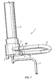
- Figure 7 shows a fourth embodiment of the end-cap assembly according to the invention.
- the end-cap 3 comprises a tubular skirt to which an end portion of the inlet port 8 and of an end portion the holder 5 are connected so as to lie in a plane substantially perpendicular to the longitudinal axis of the filter.
- a pump hose 4 is connected to the inlet port 8 and to the connector 5 and forms a loop that extends in the same plane.
- Figures 8 to 11b show a fifth embodiment of the end-cap assembly 1 according to the invention.
- the holder does not comprise a tubular connector as in the embodiments of Figures 2 to 6, but instead its leg 23 is connected to and made integral with a resilient clip 50 having a C-shaped socket 51.
- the clip 50 has a longitudinal slit-like mouth 52 for allowing the engagement of a tubular connector 53 into the socket 51.
- the connector 53 has an outside diameter corresponding to the diameter of the C-shaped socket 51 and it comprises two circular end flanges 54 for preventing the connector 53 from longitudinally moving within the socket 51 when the connector 53 is engaged in the clip 50.
- the tubular connector 53 is connected to the second end 4b of a pump hose 4, the first end 4a of which is either permanently connected to the inlet port 8 of the end-cap 3 or comprises a connecting element 4c, for example of the Luer type, for connection to a complementary connecting element included in the outlet port 8.
- the tubular connector 53 can also be pre-connected to a tube 7, as shown in Figures 10a and 11a, which represent an arterial blood line in which the tube 7 used for supplying blood from a patient to a hemodialyzer has a smaller diameter than the diameter of the pump hose 4.
- the inner bore of the connector 53 comprises a first end portion with a smaller diameter corresponding to the outer diameter of the tube 7, a second end portion with a larger diameter corresponding to the outer diameter of the pump hose 4 and an intermediary portion flaring from the first end portion to the second end portion.
- the arterial blood line comprises a connecting element at both ends, one of which is the connector element 4c adapted to the inlet port 8, the other connector element being designed for connection to a cannula.
- the internal bore of the connector 53 is cylindrical and corresponds to the outer diameter of the pump hose 4 and the tube 7 that can be made of the same piece of tubing (see Figures 10b and 11b).
- the connector 53 is merely slipped on the piece of tubing before being glued thereto at the appropriate location.
- Figure 12 shows a sixth embodiment of the end-cap assembly 1 according to the invention.
- This end-cap assembly substantially differs from the previously described embodiments in that it is designed to hold a pump hose 4 in a plane containing the central axis b of the end-cap 3.
- Figure 12 represents an end portion of a filter having a tubular housing 2 containing a bundle of hollow fibers 25 secured to the housing 2 at the end thereof by a disk of potting material 26 in which the end of the fibers 25 are embedded.
- the housing 2 is closed by an end-cap 3 having a circular end wall whose central axis 9 coincides with the longitudinal axis 9 of the housing 2.
- a pump hose support 30 in the form of an elongated rectangular parallelepiped is connected to the end-cap 3 so that the longitudinal axis of the support 30 coincides with the central axis 9 of the end-cap 3.
- the pump hose support 30 comprises two separate parts 31 and 32 that can be connected together by a mechanical coupling (not shown).
- the first part 31 of the pump hose support 30, which can be made integral with the end-cap 3, comprises a pressure measurement chamber 33 having a first and a second compartments separated by a flexible membrane 34 that lies in the plane of the figure.
- the first compartment of the pressure chamber 33 communicates with the end-cap 3 through a first portion 8a of an inlet port that extends along the central axis 9 of the end-cap 3.
- the first compartment of the pressure chamber 33 is also connected to the first end 4a of a pump hose 4 through a second portion 8b of the inlet port, whose longitudinal axis is perpendicular to the longitudinal axis 9 of the support 30.
- the first compartment of the pressure measurement chamber 33 can also be connected to a source of liquid (e.g. an infusion liquid) through a port 6 opposite to the second portion 8b of the inlet port.
- the second compartment of the pressure measurement chamber 33 comprises an aperture 10 for the connection to a pressure sensor for the measurement of the pressure of the liquid downstream of the pump hose 4.
- the second part 32 of the pump hose support 30 also comprises a pressure measurement chamber 37 having a first and a second compartments separated by a flexible membrane 38 that lies in the plane of the figure.
- the first compartment of the pressure chamber 37 is connected to a supply tube 7 through a channel 39 that extends along the longitudinal axis of the pump hose support 30.
- the first compartment of the pressure measurement chamber 37 is also connected to the second end 4b of the pump hose 4 through a channel 40, whose longitudinal axis is perpendicular to the longitudinal axis of the support 30.
- the first compartment can be connected to a source of liquid by a port 6 opposite to the channel 39.
- the second compartment of the pressure measurement chamber 37 comprises an aperture 10 for the connection to a pressure sensor for the measurement of the pressure of the liquid upstream of the pump hose 4.
Landscapes
- Health & Medical Sciences (AREA)
- Heart & Thoracic Surgery (AREA)
- Engineering & Computer Science (AREA)
- Cardiology (AREA)
- Public Health (AREA)
- Animal Behavior & Ethology (AREA)
- Veterinary Medicine (AREA)
- General Health & Medical Sciences (AREA)
- Life Sciences & Earth Sciences (AREA)
- Anesthesiology (AREA)
- Biomedical Technology (AREA)
- Hematology (AREA)
- Vascular Medicine (AREA)
- Urology & Nephrology (AREA)
- Mechanical Engineering (AREA)
- Chemical Kinetics & Catalysis (AREA)
- Chemical & Material Sciences (AREA)
- Water Supply & Treatment (AREA)
- Emergency Medicine (AREA)
- Pulmonology (AREA)
- External Artificial Organs (AREA)
- Infusion, Injection, And Reservoir Apparatuses (AREA)
- Filtration Of Liquid (AREA)
Claims (23)
- Endkappenanordnung (1) zum Schließen eines Endes eines Gehäuses (2) eines Filters, umfassend:- eine Endkappe (3) mit einer Endwand (14); und- einen Einlassport (8; 8a,8b), der sich durch die Endwand (14) erstreckt;dadurch gekennzeichnet, dass der Einlassport (8; 8a,8b) für die Verbindung mit einem ersten Ende (4a) eines Pumpenschlauchs (4) einer peristaltischen Pumpe vorgesehen ist und die Endkappenanordnung ferner einen ersten Halter (5; 5,23; 50,23; 32) zum Befestigen eines zweiten Endes (4b) des Pumpenschlauchs (4) umfasst, wobei der Einlassport (8; 8a,8b) und der erste Halter (5; 5,23; 50,23; 32) bezüglich einander so angeordnet sind, dass der Pumpenschlauch (4) eine Schleife bildet, wenn das erste Ende (4a) des Pumpenschlauchs (4) mit dem Einlassport (8) verbunden ist, und das zweite Ende (4b) des Pumpenschlauchs (4) durch den Halter (5; 5,23; 50,23; 32) befestigt ist.
- Endkappenanordnung (1) nach Anspruch 1, dadurch gekennzeichnet, dass der Einlassport (8) und der erste Halter (5; 5,23; 50,23) bezüglich einander so angeordnet sind, dass die durch den Pumpenschlauch (4) gebildete Schleife sich im Wesentlichen in einer Ebene erstreckt, die bezüglich einer senkrecht zu einer Mittelachse (9) der Endkappe (3) verlaufenden Ebene geneigt ist.
- Endkappenanordnung (1) nach einem der Ansprüche 1 und 2, dadurch gekennzeichnet, dass der Einlassport (8; 8a,8b) und der erste Halter (5; 5,23; 50,23; 32) bezüglich einander so angeordnet sind, dass das erste Ende (4a) und das zweite Ende (4b) des Pumpenschlauchs (4) voneinander in Längsrichtung bezüglich einer Mittelachse (9) der Endkappe (3) beabstandet sind, wenn das erste Ende (4a) des Pumpenschlauchs (4) mit dem Einlassport (8; 8a,8b) verbunden ist und das zweite Ende (4b) des Pumpenschlauchs (4) durch den ersten Halter (5; 5,23; 50,23; 32) befestigt ist.
- Endkappenanordnung (1) nach Anspruch 3, dadurch gekennzeichnet, dass der Einlassport (8; 8a,8b) und der Halter (5; 5,23; 50,23; 32) bezüglich einander so angeordnet sind, dass das zweite Ende (4b) des Pumpenschlauchs (4) von der Endkappe (3) weiter entfernt ist als das erste Ende (4a) des Pumpenschlauchs (4), wenn das erste Ende (4a) des Pumpenschlauchs (4) mit dem Einlassport (8; 8a,8b) verbunden ist, und das zweite Ende (4b) des Pumpenschlauchs (4) durch den ersten Halter (5; 5,23; 50,23; 32) befestigt ist.
- Endkappenanordnung (1) nach einem der Ansprüche 1 bis 4, dadurch gekennzeichnet, dass der Einlassport (8; 8a,8b) und der Halter (5; 32) bezüglich einander so angeordnet sind, dass das erste Ende (4a) und das zweite Ende (4b) des Pumpenschlauchs (4) einer Mittelachse (9) der Endkappe (3) benachbart sind, wenn das erste Ende (4a) des Pumpenschlauchs (4) mit dem Einlassport (8; 8a,8b) verbunden ist, und das zweite Ende (4b) des Pumpenschlauchs (4) durch den ersten Halter (5; 32) befestigt ist.
- Endkappenanordnung (1) nach einem der Ansprüche 1 bis 5, dadurch gekennzeichnet, dass der Einlassport (8) und der Halter (5; 5,23; 50,23) bezüglich einander so angeordnet sind, dass das erste Ende (4a) und das zweite Ende (4b) des Pumpenschlauchs (4) voneinander radial bezüglich einer Mittelachse (9) der Endkappe (3) beabstandet sind, wenn das erste Ende (4a) des Pumpenschlauchs (4) mit dem Einlassport (8) verbunden ist und das zweite Ende (4b) des Pumpenschlauchs (4) durch den ersten Halter (5; 5,23; 50,23) befestigt ist.
- Endkappenanordnung (1) nach einem der Ansprüche 1 bis 6, dadurch gekennzeichnet, dass der Einlassport (8) bezüglich einer Mittelachse (9) der Endkappe (3) versetzt ist.
- Endkappenanordnung (1) nach einem der Ansprüche 1 bis 7, dadurch gekennzeichnet, dass der Einlassport (8) einen ersten Abschnitt (18), der am weitesten von der Endwand (14) entfernt ist, einen zweiten Abschnitt (19), der der Endwand (14) am nächsten ist, und einen Zwischenabschnitt (20), der den ersten Abschnitt (18) mit dem zweiten Abschnitt (19) verbindet, umfasst, wobei der erste Abschnitt (18) eine Achse aufweist, die bezüglich einer senkrecht zu einer Mittelachse (9) der Endkappe (3) verlaufenden Ebene leicht geneigt ist, der zweite Abschnitt (19) entlang einer im Allgemeinen parallel zur Mittelachse (9) der Endkappe (3) verlaufenden Achse in Richtung auf ein Inneres (15) der Endkappe (3) abgeschrägt ist, und der Zwischenabschnitt (20) eine Krümmung aufweist, die dazu ausgelegt ist, einen glatten und unbehinderten Strom einer in die Endkappe (3) gepumpten Flüssigkeit zu erleichtern.
- Endkappenanordnung (1) nach einem der Ansprüche 1 bis 8, dadurch gekennzeichnet, dass der erste Halter (5; 5,23) einen rohrförmigen Anschluss (5) zum Verbinden eines Pumpenschlauchs (4) mit einer Leitung (7) umfasst.
- Endkappenanordnung (1) nach einem der Ansprüche 1 bis 8, dadurch gekennzeichnet, dass der erste Halter (50, 23) eine Klammer (50) zum dichten Ineingriffnehmen eines rohrförmigen Anschlusses (53) zum Verbinden eines Pumpenschlauchs (4) mit einer Leitung (7) umfasst.
- Endkappenanordnung (1) nach Anspruch 10, dadurch gekennzeichnet, dass der rohrförmige Anschluss (53) entfernbar ist und die Klammer (50) so ausgelegt ist, dass sie den rohrförmigen Anschluss (53) elastisch in Eingriff nimmt und verriegelt.
- Endkappenanordnung (1) nach einem der Ansprüche 1 bis 11, dadurch gekennzeichnet, dass der erste Halter (5,23; 50,23) einen Schenkel (23) umfasst, der an einer Peripherie der Endwand (14) der Endkappe (3) vorragt, um das zweite Ende (4b) eines Pumpenschlauchs (4) in Längsrichtung und radial von der Mittelachse (9) der Endkappe (3) beabstandet zu halten.
- Endkappenanordnung (1) nach einem der Ansprüche 1 bis 12, dadurch gekennzeichnet, dass sie ferner einen zweiten Halter (22) zum Halten eines Pumpenschlauchs (4) zwischen dem Einlassport (8) und dem ersten Halter (5) umfasst.
- Endkappenanordnung (1) nach Anspruch 13, dadurch gekennzeichnet, dass der zweite Halter (22) einen Arm umfasst, der an einer Peripherie der Endwand (14) der Endkappe (3) vorragt, um den Pumpenschlauch (4) radial von der Mittelachse (9) der Endkappe (3) beabstandet zu halten.
- Endkappenanordnung (1) nach Anspruch 1, dadurch gekennzeichnet, dass der Einlassport (8a,8b) und der erste Halter (32) bezüglich einander so angeordnet sind, dass die durch einen Pumpenschlauch (4) gebildete Schleife sich im Wesentlichen in einer parallel zu einer Mittelachse (9) der Endkappe (3) verlaufenden Ebene erstreckt, wenn das erste Ende (4a) des Pumpenschlauchs (4) mit dem Einlassport (8a,8b) verbunden ist, und das zweite Ende (4b) des Pumpenschlauchs (4) durch den ersten Halter (32) befestigt ist.
- Endkappenanordnung (1) nach einem der Ansprüche 1 bis 15, dadurch gekennzeichnet, dass der erste Halter (5,23; 32) entfernbar an der Endkappe (3) montiert ist.
- Endkappenanordnung (1) nach einem der Ansprüche 1 bis 16, dadurch gekennzeichnet, dass sie ferner mindestens einen mit dem Einlassport (8a,8b) verbundenen Infusionsport (6) umfasst.
- Endkappenanordnung (1) nach einem der Ansprüche 1 bis 17, dadurch gekennzeichnet, dass sie ferner einen Druckmessport (10) umfasst, der mit dem Einlassport (8; 8a,8b) zum Messen eines Flüssigkeitsdrucks in dem ersten Ende (4a) eines Pumpenschlauchs (4) verbunden ist.
- Endkappenanordnung (1) nach einem der Ansprüche 1 bis 18, dadurch gekennzeichnet, dass sie ferner mindestens einen Infusionsport (6a, 6b, 6c) umfasst, der mit dem ersten Halter (5; 5,23; 32) verbunden ist.
- Endkappenanordnung (1) nach einem der Ansprüche 1 bis 19, dadurch gekennzeichnet, dass sie ferner einen Druckmessport (10) umfasst, der mit dem ersten Halter (5, 32) zum Messen eines Flüssigkeitsdrucks in dem zweiten Ende (4b) eines Pumpenschlauchs (4) verbunden ist.
- Endkappenanordnung (1) nach einem der Ansprüche 1 bis 20, dadurch gekennzeichnet, dass sie ferner einen Pumpenschlauch (4) umfasst, der mit dem Einlassport (8; 8a,8b) und dem Halter (5; 5,23; 50,23; 32) verbunden ist.
- Filter, umfassend eine Endkappenanordnung gemäß einem der Ansprüche 1 bis 21.
- Filter nach Anspruch 22, umfassend eine halbdurchlässige Membran, die zur Hämodialyse und zum Hämofiltrieren ausgelegt ist.
Priority Applications (1)
| Application Number | Priority Date | Filing Date | Title |
|---|---|---|---|
| EP04024751A EP1530995B1 (de) | 2003-11-07 | 2004-10-18 | Endkappenanordnung mit einem schlauch für eine pumpe für ein filter und filter mit einer solchen endkappenanordnung |
Applications Claiming Priority (3)
| Application Number | Priority Date | Filing Date | Title |
|---|---|---|---|
| EP03025640 | 2003-11-07 | ||
| EP03025640 | 2003-11-07 | ||
| EP04024751A EP1530995B1 (de) | 2003-11-07 | 2004-10-18 | Endkappenanordnung mit einem schlauch für eine pumpe für ein filter und filter mit einer solchen endkappenanordnung |
Publications (2)
| Publication Number | Publication Date |
|---|---|
| EP1530995A1 EP1530995A1 (de) | 2005-05-18 |
| EP1530995B1 true EP1530995B1 (de) | 2007-02-21 |
Family
ID=34560156
Family Applications (1)
| Application Number | Title | Priority Date | Filing Date |
|---|---|---|---|
| EP04024751A Expired - Lifetime EP1530995B1 (de) | 2003-11-07 | 2004-10-18 | Endkappenanordnung mit einem schlauch für eine pumpe für ein filter und filter mit einer solchen endkappenanordnung |
Country Status (10)
| Country | Link |
|---|---|
| US (1) | US8403150B2 (de) |
| EP (1) | EP1530995B1 (de) |
| KR (1) | KR101188573B1 (de) |
| CN (3) | CN100406108C (de) |
| AT (1) | ATE354429T1 (de) |
| AU (1) | AU2004286774B2 (de) |
| CA (1) | CA2543519C (de) |
| DE (1) | DE602004004857T2 (de) |
| ES (1) | ES2282775T3 (de) |
| WO (1) | WO2005044428A1 (de) |
Families Citing this family (40)
| Publication number | Priority date | Publication date | Assignee | Title |
|---|---|---|---|---|
| AU2008251056B2 (en) * | 2007-05-15 | 2013-01-10 | Gambro Lundia Ab | Pressure sensing device and use of the same in a connecting structure |
| EP2113266A1 (de) * | 2008-04-30 | 2009-11-04 | Gambro Lundia AB | Entgasungsvorrichtung |
| GB0812457D0 (en) * | 2008-07-08 | 2008-08-13 | Parker Hannifin U K Ltd | A Filter |
| DE102009038571B4 (de) * | 2009-08-22 | 2011-07-14 | Völker, Manfred, 63825 | Versorgungseinrichtung für Dialysegeräte |
| US9228575B2 (en) * | 2010-11-16 | 2016-01-05 | Zoeller Pump Company, Llc | Sealed and self-contained tankless water heater flushing system |
| US9173987B2 (en) * | 2013-02-01 | 2015-11-03 | Medtronic, Inc. | Degassing module for a controlled compliant flow path |
| US9404488B2 (en) * | 2013-02-19 | 2016-08-02 | Wabtec Holding Corp. | Pressurized oil delivery system for a reciprocating air compressor |
| TW201521818A (zh) | 2013-08-29 | 2015-06-16 | Sanofi Sa | 用於藥物容器之安全裝置 |
| KR102121918B1 (ko) * | 2013-12-20 | 2020-06-11 | 삼성전자주식회사 | 홈 네트워크 시스템에서 이벤트 통지 방법 및 장치 |
| WO2017092795A1 (fr) * | 2015-12-01 | 2017-06-08 | Ateliers Busch S.A. | Pompe a vide avec element filtrant |
| CN109715266B (zh) | 2016-10-20 | 2021-11-30 | Emd密理博公司 | 阀门保护和管路管理装置 |
| EP4732889A2 (de) | 2017-06-07 | 2026-04-29 | Supira Medical, Inc. | Vorrichtungen, systeme und verfahren zur bewegung intravaskulärer flüssigkeiten |
| JP7319266B2 (ja) | 2017-11-13 | 2023-08-01 | シファメド・ホールディングス・エルエルシー | 血管内流体移動デバイス、システム、および使用方法 |
| EP4085965A1 (de) | 2018-02-01 | 2022-11-09 | Shifamed Holdings, LLC | Intravaskuläre blutpumpen und verfahren zur verwendung und herstellung |
| CN108295326B (zh) * | 2018-02-09 | 2021-03-26 | 苏州卓壹医疗器械有限公司 | 一种双腔超纯血液透析器 |
| JP6577626B1 (ja) * | 2018-05-02 | 2019-09-18 | 日機装株式会社 | エアトラップチャンバ及び体外循環回路 |
| US12161857B2 (en) | 2018-07-31 | 2024-12-10 | Shifamed Holdings, Llc | Intravascular blood pumps and methods of use |
| WO2020073047A1 (en) | 2018-10-05 | 2020-04-09 | Shifamed Holdings, Llc | Intravascular blood pumps and methods of use |
| USD910081S1 (en) * | 2019-02-14 | 2021-02-09 | Fleece Performance Engineering, Inc. | Pump cap |
| USD910082S1 (en) * | 2019-04-17 | 2021-02-09 | Fleece Performance Engineering, Inc. | Pump cap |
| USD910083S1 (en) * | 2019-05-08 | 2021-02-09 | Fleece Performance Engineering, Inc. | Pump cap |
| EP3996797A4 (de) | 2019-07-12 | 2023-08-02 | Shifamed Holdings, LLC | Intravaskuläre blutpumpen und verfahren zur herstellung und verwendung |
| US11654275B2 (en) | 2019-07-22 | 2023-05-23 | Shifamed Holdings, Llc | Intravascular blood pumps with struts and methods of use and manufacture |
| EP4010046A4 (de) | 2019-08-07 | 2023-08-30 | Calomeni, Michael | Katheterblutpumpen und zusammenklappbare pumpengehäuse |
| US12121713B2 (en) | 2019-09-25 | 2024-10-22 | Shifamed Holdings, Llc | Catheter blood pumps and collapsible blood conduits |
| EP4034192B1 (de) | 2019-09-25 | 2025-12-24 | Supira Medical, Inc. | Intravaskuläre blutpumpensysteme und verfahren zur verwendung und steuerung davon |
| US12102815B2 (en) | 2019-09-25 | 2024-10-01 | Shifamed Holdings, Llc | Catheter blood pumps and collapsible pump housings |
| CA3160871A1 (en) | 2019-11-12 | 2021-05-20 | Fresenius Medical Care Deutschland Gmbh | Blood treatment systems |
| CN114728117B (zh) | 2019-11-12 | 2025-11-11 | 费森尤斯医疗护理德国有限责任公司 | 血液治疗系统 |
| CA3160967A1 (en) | 2019-11-12 | 2021-05-20 | Fresenius Medical Care Deutschland Gmbh | Blood treatment systems |
| CN114728159B (zh) | 2019-11-12 | 2025-10-17 | 费森尤斯医疗护理德国有限责任公司 | 血液治疗系统 |
| CA3160952A1 (en) | 2019-11-12 | 2021-05-20 | Fresenius Medical Care Deutschland Gmbh | Blood treatment systems |
| EP4058094A1 (de) | 2019-11-12 | 2022-09-21 | Fresenius Medical Care Deutschland GmbH | Blutbehandlungssysteme |
| EP4072650A4 (de) | 2019-12-11 | 2024-01-10 | Shifamed Holdings, LLC | Absteigende aorten- und hohlvenenblutpumpen |
| WO2021119401A1 (en) | 2019-12-12 | 2021-06-17 | Fresenius Medical Care Holdings, Inc. | Blood treatment systems |
| WO2021127503A1 (en) | 2019-12-19 | 2021-06-24 | Shifamed Holdings, Llc | Intravascular blood pumps, motors, and fluid control |
| EP3900814B1 (de) * | 2020-04-23 | 2025-07-30 | Bellco S.r.l. | Dialysatorkopfkappe |
| USD996211S1 (en) * | 2020-05-18 | 2023-08-22 | Illinois Tool Works Inc. | Sealant bottle cap |
| USD985632S1 (en) * | 2021-06-30 | 2023-05-09 | Fleece Performance Engineering, Inc. | Pump cap |
| CN118767235A (zh) * | 2024-06-24 | 2024-10-15 | 恩基(苏州)智慧医疗科技有限公司 | 一种快换式血液透析用透析机 |
Family Cites Families (51)
| Publication number | Priority date | Publication date | Assignee | Title |
|---|---|---|---|---|
| US4436620A (en) | 1977-05-09 | 1984-03-13 | Baxter Travenol Laboratories, Inc. | Integral hydraulic circuit for hemodialysis apparatus |
| US4231871A (en) | 1977-06-10 | 1980-11-04 | Cordis Dow Corp. | Artificial kidney and method for making same |
| US4379452A (en) | 1977-10-18 | 1983-04-12 | Baxter Travenol Laboratories, Inc. | Prepackaged, self-contained fluid circuit module |
| DE2818390C2 (de) | 1978-04-27 | 1986-10-30 | Fresenius AG, 6380 Bad Homburg | Künstliches Organ |
| JPS55114A (en) | 1978-06-15 | 1980-01-05 | Honda Motor Co Ltd | Dialyzer device in artificial kidney device |
| US4263808A (en) * | 1979-03-26 | 1981-04-28 | Baxter Travenol Laboratories, Inc. | Noninvasive pressure monitor |
| US4227420A (en) | 1979-06-11 | 1980-10-14 | Baxter Travenol Laboratories, Inc. | Pressure coupling mechanism in a pressure monitoring assembly |
| US4293413A (en) | 1979-12-28 | 1981-10-06 | Baxter Travenol Laboratories, Inc. | Dialyzer blood circuit and bubble traps |
| US4344777A (en) | 1980-01-07 | 1982-08-17 | Siposs George G | Directed flow bubble trap for arterial blood |
| US4368118A (en) | 1980-01-07 | 1983-01-11 | Siposs George G | Blood-air separator and filter |
| FR2491336A1 (fr) | 1980-10-06 | 1982-04-09 | Hospal Sodip | Rein artificiel avec circuit de liquide de dialyse a usage unique |
| FR2493706A1 (fr) | 1980-11-13 | 1982-05-14 | Hospal Sodip | Rein artificiel avec circuit de liquide de dialyse integre |
| FR2507481B1 (fr) | 1981-06-16 | 1985-06-14 | Hospal Sodip | Rein artificiel avec circuits integres |
| US4412916A (en) | 1981-06-24 | 1983-11-01 | Cordis Dow Corp. | Airless artificial kidney assembly |
| US4433971A (en) * | 1981-06-30 | 1984-02-28 | Minnesota Mining And Manufacturing Company | Integrated cardioplegia delivery system |
| IL64001A0 (en) | 1981-10-06 | 1982-01-31 | Elmar Medical Systems Ltd | Blood treatment system |
| US4582598A (en) | 1981-12-15 | 1986-04-15 | Baxter Travenol Laboratories, Inc. | Replacement fluid control system for a blood fractionation apparatus and the like |
| US4493693A (en) * | 1982-07-30 | 1985-01-15 | Baxter Travenol Laboratories, Inc. | Trans-membrane pressure monitoring system |
| US4479761A (en) | 1982-12-28 | 1984-10-30 | Baxter Travenol Laboratories, Inc. | Actuator apparatus for a prepackaged fluid processing module having pump and valve elements operable in response to externally applied pressures |
| US4479760A (en) | 1982-12-28 | 1984-10-30 | Baxter Travenol Laboratories, Inc. | Actuator apparatus for a prepackaged fluid processing module having pump and valve elements operable in response to applied pressures |
| US4479762A (en) | 1982-12-28 | 1984-10-30 | Baxter Travenol Laboratories, Inc. | Prepackaged fluid processing module having pump and valve elements operable in response to applied pressures |
| US4605503A (en) * | 1983-05-26 | 1986-08-12 | Baxter Travenol Laboratories, Inc. | Single needle blood fractionation system having adjustable recirculation through filter |
| US4666598A (en) | 1985-06-25 | 1987-05-19 | Cobe Laboratories, Inc. | Apparatus for use with fluid flow transfer device |
| US4798090A (en) | 1985-06-25 | 1989-01-17 | Cobe Laboratories, Inc. | Apparatus for use with fluid flow transfer device |
| US4770787A (en) * | 1985-06-25 | 1988-09-13 | Cobe Laboratories, Inc. | Method of operating a fluid flow transfer device |
| US4676467A (en) | 1985-10-31 | 1987-06-30 | Cobe Laboratories, Inc. | Apparatus for supporting a fluid flow cassette |
| IT1189118B (it) | 1986-05-12 | 1988-01-28 | Dideco Spa | Dispositivo per la filtrazione di sangue arterioso |
| IT1210742B (it) * | 1987-05-18 | 1989-09-20 | Sorin Biomedica Spa | Dispositivo ossigenatore a fibre cave |
| US4824339A (en) | 1987-08-19 | 1989-04-25 | Cobe Laboratories, Inc. | Peristaltic pump cartridge |
| US4806135A (en) | 1988-03-01 | 1989-02-21 | Siposs George G | Bubble trap for phase-separating gas bubbles from flowing liquids |
| US5382407A (en) | 1988-12-14 | 1995-01-17 | Minnesota Mining And Manufacturing Company | Membrane blood oxygenator |
| NZ236033A (en) * | 1989-11-13 | 1994-11-25 | Davol Inc | Blood pump: filtering with tangential flow separation |
| US5200090A (en) | 1990-03-30 | 1993-04-06 | Baxter International Inc. | Multiple fluid source isolation, metering and alarm system and method |
| US5362406A (en) | 1990-07-27 | 1994-11-08 | Pall Corporation | Leucocyte depleting filter device and method of use |
| US5130020A (en) * | 1990-08-30 | 1992-07-14 | Meckstroth Alan F | Portable water filter unit having storage space for flexible tubes |
| DE4027531C1 (en) | 1990-08-31 | 1991-07-25 | Fresenius Ag, 6380 Bad Homburg, De | Filter for sterilising aq. soln. e.g. dialysis liq. - where incoming liq. flows between 1st antechamber, and fibre interiors into 2nd antechamber |
| US5441636A (en) | 1993-02-12 | 1995-08-15 | Cobe Laboratories, Inc. | Integrated blood treatment fluid module |
| DE4321927C2 (de) | 1993-07-01 | 1998-07-09 | Sartorius Gmbh | Filtereinheit mit Entgasungsvorrichtung |
| CA2142413A1 (en) | 1994-02-15 | 1995-08-16 | Wesley H. Verkarrt | Vortex gas elimination device |
| US5795317A (en) | 1995-06-07 | 1998-08-18 | Cobe Laboratories, Inc. | Extracorporeal blood processing methods and apparatus |
| DE19617036C2 (de) | 1996-04-27 | 2003-12-04 | Fresenius Ag | Vorrichtung zum Abscheiden von Gasblasen aus Blut |
| DE19620591B4 (de) * | 1996-05-22 | 2004-08-26 | Fresenius Medical Care Deutschland Gmbh | Vorrichtung zum Entfernen von Gasen aus Flüssigkeiten |
| US6071269A (en) | 1998-05-13 | 2000-06-06 | Medisystems Technology Corporation | Blood set and chamber |
| US6695803B1 (en) | 1998-10-16 | 2004-02-24 | Mission Medical, Inc. | Blood processing system |
| AU1334600A (en) | 1998-11-02 | 2000-05-22 | Lifestream International, Inc. | Cardioplegia heat exchanger |
| US7041076B1 (en) * | 1999-09-03 | 2006-05-09 | Baxter International Inc. | Blood separation systems and methods using a multiple function pump station to perform different on-line processing tasks |
| DE10007327A1 (de) * | 2000-02-17 | 2001-08-30 | Fresenius Medical Care De Gmbh | Filtervorrichtung, vorzugsweise Hohlfaserdialysator mit gelockten Hohlfasern |
| US6916424B2 (en) * | 2001-02-07 | 2005-07-12 | Nephros, Inc. | Method and apparatus for a hemodiafiltration delivery module |
| US6582386B2 (en) | 2001-03-06 | 2003-06-24 | Baxter International Inc. | Multi-purpose, automated blood and fluid processing systems and methods |
| USD479320S1 (en) | 2002-04-03 | 2003-09-02 | Chf Solutions, Inc. | Blood filter and tubing harness for extracorporeal blood treatment |
| EP1466657B1 (de) * | 2003-04-11 | 2012-10-03 | Gambro Lundia AB | Filterapparat mit mehr als einer Filtrationskammer |
-
2004
- 2004-10-18 EP EP04024751A patent/EP1530995B1/de not_active Expired - Lifetime
- 2004-10-18 WO PCT/EP2004/011707 patent/WO2005044428A1/en not_active Ceased
- 2004-10-18 AU AU2004286774A patent/AU2004286774B2/en not_active Ceased
- 2004-10-18 KR KR1020067008417A patent/KR101188573B1/ko not_active Expired - Fee Related
- 2004-10-18 DE DE602004004857T patent/DE602004004857T2/de not_active Expired - Lifetime
- 2004-10-18 ES ES04024751T patent/ES2282775T3/es not_active Expired - Lifetime
- 2004-10-18 CA CA2543519A patent/CA2543519C/en not_active Expired - Fee Related
- 2004-10-18 CN CNB2004800323430A patent/CN100406108C/zh not_active Expired - Fee Related
- 2004-10-18 AT AT04024751T patent/ATE354429T1/de not_active IP Right Cessation
- 2004-10-29 CN CN2004800323411A patent/CN1874804B/zh not_active Expired - Fee Related
- 2004-11-05 CN CN200480032345A patent/CN100586494C/zh not_active Expired - Fee Related
-
2006
- 2006-04-21 US US11/379,725 patent/US8403150B2/en active Active
Also Published As
| Publication number | Publication date |
|---|---|
| AU2004286774A1 (en) | 2005-05-19 |
| HK1097792A1 (zh) | 2007-07-06 |
| ATE354429T1 (de) | 2007-03-15 |
| CN1874837A (zh) | 2006-12-06 |
| KR20060113686A (ko) | 2006-11-02 |
| CN1874805A (zh) | 2006-12-06 |
| ES2282775T3 (es) | 2007-10-16 |
| CA2543519A1 (en) | 2005-05-19 |
| CN100586494C (zh) | 2010-02-03 |
| CN1874804B (zh) | 2010-08-25 |
| EP1530995A1 (de) | 2005-05-18 |
| CA2543519C (en) | 2012-12-11 |
| US20090020468A1 (en) | 2009-01-22 |
| US8403150B2 (en) | 2013-03-26 |
| WO2005044428A1 (en) | 2005-05-19 |
| DE602004004857T2 (de) | 2007-10-25 |
| CN100406108C (zh) | 2008-07-30 |
| DE602004004857D1 (de) | 2007-04-05 |
| CN1874804A (zh) | 2006-12-06 |
| AU2004286774B2 (en) | 2010-12-02 |
| KR101188573B1 (ko) | 2012-10-05 |
Similar Documents
| Publication | Publication Date | Title |
|---|---|---|
| EP1530995B1 (de) | Endkappenanordnung mit einem schlauch für eine pumpe für ein filter und filter mit einer solchen endkappenanordnung | |
| EP1529545B1 (de) | Integriertes Blutbehandlungsmodul | |
| JP3784071B2 (ja) | 透析血液配管セット | |
| CA2544612C (en) | Degassing device and end-cap assembly for a filter including such a degassing device | |
| US11246972B2 (en) | Universal portable machine for online hemodiafiltration using regenerated dialysate | |
| US7993516B2 (en) | Integrated blood treatment module and extracorporeal blood treatment apparatus | |
| HK1097792B (en) | End-cap assembly with pump hose for a filter and filter comprising such an end-cap assembly | |
| HK1097784B (en) | Fluid distribution module and extracorporeal blood circuit including such a module |
Legal Events
| Date | Code | Title | Description |
|---|---|---|---|
| PUAI | Public reference made under article 153(3) epc to a published international application that has entered the european phase |
Free format text: ORIGINAL CODE: 0009012 |
|
| AK | Designated contracting states |
Kind code of ref document: A1 Designated state(s): AT BE BG CH CY CZ DE DK EE ES FI FR GB GR HU IE IT LI LU MC NL PL PT RO SE SI SK TR |
|
| AX | Request for extension of the european patent |
Extension state: AL HR LT LV MK |
|
| 17P | Request for examination filed |
Effective date: 20050628 |
|
| AKX | Designation fees paid |
Designated state(s): AT BE BG CH CY CZ DE DK EE ES FI FR GB GR HU IE IT LI LU MC NL PL PT RO SE SI SK TR |
|
| GRAP | Despatch of communication of intention to grant a patent |
Free format text: ORIGINAL CODE: EPIDOSNIGR1 |
|
| GRAS | Grant fee paid |
Free format text: ORIGINAL CODE: EPIDOSNIGR3 |
|
| GRAA | (expected) grant |
Free format text: ORIGINAL CODE: 0009210 |
|
| AK | Designated contracting states |
Kind code of ref document: B1 Designated state(s): AT BE BG CH CY CZ DE DK EE ES FI FR GB GR HU IE IT LI LU MC NL PL PT RO SE SI SK TR |
|
| PG25 | Lapsed in a contracting state [announced via postgrant information from national office to epo] |
Ref country code: PL Free format text: LAPSE BECAUSE OF FAILURE TO SUBMIT A TRANSLATION OF THE DESCRIPTION OR TO PAY THE FEE WITHIN THE PRESCRIBED TIME-LIMIT Effective date: 20070221 Ref country code: NL Free format text: LAPSE BECAUSE OF FAILURE TO SUBMIT A TRANSLATION OF THE DESCRIPTION OR TO PAY THE FEE WITHIN THE PRESCRIBED TIME-LIMIT Effective date: 20070221 Ref country code: LI Free format text: LAPSE BECAUSE OF FAILURE TO SUBMIT A TRANSLATION OF THE DESCRIPTION OR TO PAY THE FEE WITHIN THE PRESCRIBED TIME-LIMIT Effective date: 20070221 Ref country code: AT Free format text: LAPSE BECAUSE OF FAILURE TO SUBMIT A TRANSLATION OF THE DESCRIPTION OR TO PAY THE FEE WITHIN THE PRESCRIBED TIME-LIMIT Effective date: 20070221 Ref country code: SI Free format text: LAPSE BECAUSE OF FAILURE TO SUBMIT A TRANSLATION OF THE DESCRIPTION OR TO PAY THE FEE WITHIN THE PRESCRIBED TIME-LIMIT Effective date: 20070221 Ref country code: CH Free format text: LAPSE BECAUSE OF FAILURE TO SUBMIT A TRANSLATION OF THE DESCRIPTION OR TO PAY THE FEE WITHIN THE PRESCRIBED TIME-LIMIT Effective date: 20070221 Ref country code: BE Free format text: LAPSE BECAUSE OF FAILURE TO SUBMIT A TRANSLATION OF THE DESCRIPTION OR TO PAY THE FEE WITHIN THE PRESCRIBED TIME-LIMIT Effective date: 20070221 Ref country code: FI Free format text: LAPSE BECAUSE OF FAILURE TO SUBMIT A TRANSLATION OF THE DESCRIPTION OR TO PAY THE FEE WITHIN THE PRESCRIBED TIME-LIMIT Effective date: 20070221 Ref country code: DK Free format text: LAPSE BECAUSE OF FAILURE TO SUBMIT A TRANSLATION OF THE DESCRIPTION OR TO PAY THE FEE WITHIN THE PRESCRIBED TIME-LIMIT Effective date: 20070221 |
|
| REG | Reference to a national code |
Ref country code: GB Ref legal event code: FG4D |
|
| REG | Reference to a national code |
Ref country code: CH Ref legal event code: EP |
|
| REF | Corresponds to: |
Ref document number: 602004004857 Country of ref document: DE Date of ref document: 20070405 Kind code of ref document: P |
|
| REG | Reference to a national code |
Ref country code: IE Ref legal event code: FG4D |
|
| PG25 | Lapsed in a contracting state [announced via postgrant information from national office to epo] |
Ref country code: SE Free format text: LAPSE BECAUSE OF FAILURE TO SUBMIT A TRANSLATION OF THE DESCRIPTION OR TO PAY THE FEE WITHIN THE PRESCRIBED TIME-LIMIT Effective date: 20070521 |
|
| PG25 | Lapsed in a contracting state [announced via postgrant information from national office to epo] |
Ref country code: BG Free format text: LAPSE BECAUSE OF FAILURE TO SUBMIT A TRANSLATION OF THE DESCRIPTION OR TO PAY THE FEE WITHIN THE PRESCRIBED TIME-LIMIT Effective date: 20070522 |
|
| PG25 | Lapsed in a contracting state [announced via postgrant information from national office to epo] |
Ref country code: PT Free format text: LAPSE BECAUSE OF FAILURE TO SUBMIT A TRANSLATION OF THE DESCRIPTION OR TO PAY THE FEE WITHIN THE PRESCRIBED TIME-LIMIT Effective date: 20070723 |
|
| NLV1 | Nl: lapsed or annulled due to failure to fulfill the requirements of art. 29p and 29m of the patents act | ||
| ET | Fr: translation filed | ||
| REG | Reference to a national code |
Ref country code: CH Ref legal event code: PL |
|
| REG | Reference to a national code |
Ref country code: ES Ref legal event code: FG2A Ref document number: 2282775 Country of ref document: ES Kind code of ref document: T3 |
|
| PG25 | Lapsed in a contracting state [announced via postgrant information from national office to epo] |
Ref country code: SK Free format text: LAPSE BECAUSE OF FAILURE TO SUBMIT A TRANSLATION OF THE DESCRIPTION OR TO PAY THE FEE WITHIN THE PRESCRIBED TIME-LIMIT Effective date: 20070221 |
|
| PLBE | No opposition filed within time limit |
Free format text: ORIGINAL CODE: 0009261 |
|
| STAA | Information on the status of an ep patent application or granted ep patent |
Free format text: STATUS: NO OPPOSITION FILED WITHIN TIME LIMIT |
|
| PG25 | Lapsed in a contracting state [announced via postgrant information from national office to epo] |
Ref country code: CZ Free format text: LAPSE BECAUSE OF FAILURE TO SUBMIT A TRANSLATION OF THE DESCRIPTION OR TO PAY THE FEE WITHIN THE PRESCRIBED TIME-LIMIT Effective date: 20070221 Ref country code: RO Free format text: LAPSE BECAUSE OF FAILURE TO SUBMIT A TRANSLATION OF THE DESCRIPTION OR TO PAY THE FEE WITHIN THE PRESCRIBED TIME-LIMIT Effective date: 20070221 |
|
| 26N | No opposition filed |
Effective date: 20071122 |
|
| PG25 | Lapsed in a contracting state [announced via postgrant information from national office to epo] |
Ref country code: GR Free format text: LAPSE BECAUSE OF FAILURE TO SUBMIT A TRANSLATION OF THE DESCRIPTION OR TO PAY THE FEE WITHIN THE PRESCRIBED TIME-LIMIT Effective date: 20070522 |
|
| PG25 | Lapsed in a contracting state [announced via postgrant information from national office to epo] |
Ref country code: MC Free format text: LAPSE BECAUSE OF NON-PAYMENT OF DUE FEES Effective date: 20071031 |
|
| REG | Reference to a national code |
Ref country code: GB Ref legal event code: 732E |
|
| PG25 | Lapsed in a contracting state [announced via postgrant information from national office to epo] |
Ref country code: IE Free format text: LAPSE BECAUSE OF NON-PAYMENT OF DUE FEES Effective date: 20071018 |
|
| PG25 | Lapsed in a contracting state [announced via postgrant information from national office to epo] |
Ref country code: EE Free format text: LAPSE BECAUSE OF FAILURE TO SUBMIT A TRANSLATION OF THE DESCRIPTION OR TO PAY THE FEE WITHIN THE PRESCRIBED TIME-LIMIT Effective date: 20070221 |
|
| REG | Reference to a national code |
Ref country code: FR Ref legal event code: GC |
|
| PG25 | Lapsed in a contracting state [announced via postgrant information from national office to epo] |
Ref country code: CY Free format text: LAPSE BECAUSE OF FAILURE TO SUBMIT A TRANSLATION OF THE DESCRIPTION OR TO PAY THE FEE WITHIN THE PRESCRIBED TIME-LIMIT Effective date: 20070221 |
|
| PG25 | Lapsed in a contracting state [announced via postgrant information from national office to epo] |
Ref country code: LU Free format text: LAPSE BECAUSE OF NON-PAYMENT OF DUE FEES Effective date: 20071018 |
|
| PG25 | Lapsed in a contracting state [announced via postgrant information from national office to epo] |
Ref country code: TR Free format text: LAPSE BECAUSE OF FAILURE TO SUBMIT A TRANSLATION OF THE DESCRIPTION OR TO PAY THE FEE WITHIN THE PRESCRIBED TIME-LIMIT Effective date: 20070221 Ref country code: HU Free format text: LAPSE BECAUSE OF FAILURE TO SUBMIT A TRANSLATION OF THE DESCRIPTION OR TO PAY THE FEE WITHIN THE PRESCRIBED TIME-LIMIT Effective date: 20070822 |
|
| REG | Reference to a national code |
Ref country code: FR Ref legal event code: RG Effective date: 20120215 |
|
| PGFP | Annual fee paid to national office [announced via postgrant information from national office to epo] |
Ref country code: ES Payment date: 20141016 Year of fee payment: 11 |
|
| REG | Reference to a national code |
Ref country code: FR Ref legal event code: PLFP Year of fee payment: 13 |
|
| REG | Reference to a national code |
Ref country code: ES Ref legal event code: FD2A Effective date: 20161128 |
|
| PG25 | Lapsed in a contracting state [announced via postgrant information from national office to epo] |
Ref country code: ES Free format text: LAPSE BECAUSE OF NON-PAYMENT OF DUE FEES Effective date: 20151019 |
|
| REG | Reference to a national code |
Ref country code: FR Ref legal event code: PLFP Year of fee payment: 14 |
|
| REG | Reference to a national code |
Ref country code: FR Ref legal event code: PLFP Year of fee payment: 15 |
|
| PGFP | Annual fee paid to national office [announced via postgrant information from national office to epo] |
Ref country code: IT Payment date: 20180920 Year of fee payment: 15 Ref country code: FR Payment date: 20180911 Year of fee payment: 15 |
|
| PGFP | Annual fee paid to national office [announced via postgrant information from national office to epo] |
Ref country code: GB Payment date: 20180914 Year of fee payment: 15 |
|
| PGFP | Annual fee paid to national office [announced via postgrant information from national office to epo] |
Ref country code: DE Payment date: 20180912 Year of fee payment: 15 |
|
| REG | Reference to a national code |
Ref country code: DE Ref legal event code: R119 Ref document number: 602004004857 Country of ref document: DE |
|
| PG25 | Lapsed in a contracting state [announced via postgrant information from national office to epo] |
Ref country code: DE Free format text: LAPSE BECAUSE OF NON-PAYMENT OF DUE FEES Effective date: 20200501 |
|
| GBPC | Gb: european patent ceased through non-payment of renewal fee |
Effective date: 20191018 |
|
| PG25 | Lapsed in a contracting state [announced via postgrant information from national office to epo] |
Ref country code: GB Free format text: LAPSE BECAUSE OF NON-PAYMENT OF DUE FEES Effective date: 20191018 Ref country code: IT Free format text: LAPSE BECAUSE OF NON-PAYMENT OF DUE FEES Effective date: 20191018 Ref country code: FR Free format text: LAPSE BECAUSE OF NON-PAYMENT OF DUE FEES Effective date: 20191031 |