EP1530897A2 - Rack for animal feed - Google Patents
Rack for animal feed Download PDFInfo
- Publication number
- EP1530897A2 EP1530897A2 EP04292686A EP04292686A EP1530897A2 EP 1530897 A2 EP1530897 A2 EP 1530897A2 EP 04292686 A EP04292686 A EP 04292686A EP 04292686 A EP04292686 A EP 04292686A EP 1530897 A2 EP1530897 A2 EP 1530897A2
- Authority
- EP
- European Patent Office
- Prior art keywords
- frame
- rack
- grid
- uprights
- pivot
- Prior art date
- Legal status (The legal status is an assumption and is not a legal conclusion. Google has not performed a legal analysis and makes no representation as to the accuracy of the status listed.)
- Granted
Links
Images


Classifications
-
- A—HUMAN NECESSITIES
- A01—AGRICULTURE; FORESTRY; ANIMAL HUSBANDRY; HUNTING; TRAPPING; FISHING
- A01K—ANIMAL HUSBANDRY; CARE OF BIRDS, FISHES, INSECTS; FISHING; REARING OR BREEDING ANIMALS, NOT OTHERWISE PROVIDED FOR; NEW BREEDS OF ANIMALS
- A01K1/00—Housing animals; Equipment therefor
- A01K1/10—Feed racks
-
- A—HUMAN NECESSITIES
- A01—AGRICULTURE; FORESTRY; ANIMAL HUSBANDRY; HUNTING; TRAPPING; FISHING
- A01K—ANIMAL HUSBANDRY; CARE OF BIRDS, FISHES, INSECTS; FISHING; REARING OR BREEDING ANIMALS, NOT OTHERWISE PROVIDED FOR; NEW BREEDS OF ANIMALS
- A01K1/00—Housing animals; Equipment therefor
- A01K1/0005—Stable partitions
- A01K1/0017—Gates, doors
Definitions
- the present invention relates to a rack for receiving the fodder constituting part of the feeding of farm animals, in particular cattle.
- Some racks known in the prior art are round or square, and allow to accommodate one or two round boots maximum. The breeder laying on the ground in loose housing, fixing them on the ground or not. These racks have the disadvantage of obliging the farmer to enter the stall recharge the racks with fodder, which can be detrimental to their safety. Another disadvantage of these racks is that they take up room on the floor and leave therefore less room for the movement of animals.
- the present invention aims to overcome certain disadvantages of the prior art by providing a rack that allows to contain several Fodder boots, which can be reloaded without risk for the breeder from outside the stall and without handling the boots, which can accommodate either round or square boots, which does not interfere movement of animals in the lairage and does not interfere with their space that is easy to transport and install and can be galvanized.
- a rack intended to receive at least one boot fodder for feeding farm animals, characterized in that it is consisting of a frame and at least two uprights, removably attached on each side of the plane of symmetry of the frame, the amounts on which dismountably fixed respectively a surface and a flat grid, the planes of symmetry of the surface and the grid being intersecting with each other, the surface and the grid being intended to support the forage boot (s), and animals feeding through the gap between the bars of the grid, in that the frame is demountably attached between two poles, so as to be able to pivot around one of the posts to realize a barrier to block animals inside the building close or remove them from the building when the farmer so decides.
- the various elements constituting the rack are galvanizable.
- the frame is substantially rectangular and consisting of two horizontal uprights and two vertical uprights, what, on the animal side, the amounts consist of at least two bars tubular bent substantially ear-shaped or "C" inverted, say Extreme tubular bars, removably attached to studs the horizontal of the frame, each near one of the vertical uprights of framework, and in that, on the other side of the frame with respect to animals, the uprights are external uprights removably attached to the bars extreme tubulars to form each with the surface and the frame a triangle.
- the space formed between the triangles constituted by the outer uprights with the surface and the frame is free to allow loading from outside the rack.
- animal side at least one bar tubular bent, substantially shaped ear or "C” inverted, said (s) intermediate tubular bar (s), is removably attached to horizontal amounts of the frame, between the extreme tubular bars.
- the grid is fixed to each of the bars extreme or intermediate tubulars, and in that the surface is attached to the times to the outside uprights and to the lower horizontal upright of the frame.
- the surface is made of sheet metal and provided with a plurality of ribs to avoid a "sucker" effect.
- each extreme tubular bar and each outer amount is provided with a grid to retain the feed.
- the surface is inclined at an angle ⁇ by vertically, and in that the grid is inclined at an angle ⁇ by vertical ratio.
- ⁇ is of the order of 20 ° to 40 ° and ⁇ of the order of 30 ° to 60 °.
- the rack is provided, under the frame, with a reinforcement bar.
- the rack according to the invention represented in particular in FIG. comprises a frame (1), visible in particular in Figures 2 and 3.
- This frame (1) consists of four substantially orthogonal amounts each other.
- the two vertical uprights of the frame are fixed, as will be seen further, between the posts (7a, 7b) located at the entrance of a farm building, the rack according to the invention replacing the barrier allowing the entry and the exit of the animals.
- the frame is provided at its lower end with a reinforcing bar (10) tubular located in the same plane as the frame (1).
- This reinforcing bar is for example fixed in several places of the amount lower part of the frame, by welding with a plurality of tubes, as shown in Figure 2.
- the distance between the bottom of the bar reinforcement (10) and the ground should be smaller than the average snout cattle, so that they do not get caught in the muzzle under the rack.
- the frame (1) also comprises, on each of its amounts horizontal plates, a plurality of plates (11) each provided with at least one drilling.
- the rack according to the invention also comprises a plurality of bent tubular bars (2, 3) substantially in the form of an ear or "C" inverted, each contained in a plane substantially orthogonal to the plane of the frame (1).
- Two of the bent tubular bars, called tubular bars extremes (2), are respectively fixed at each end of the frame (1) of the rack, while the other bent tubular bars, called bars intermediate tubes (3) are fixed to the frame and distributed between the extreme tubular bars (2), as shown in particular on the FIG. 2.
- the rack according to the invention comprises, for example, three bars intermediate tubulars (3).
- each end or intermediate tubular bar (2, 3) is provided with each of its ends with a hook (21, 31) provided with at least one drilling.
- Each of the hooks (21, 31) is intended to suspend the bar extreme or intermediate tubular (2, 3) on the horizontal uprights of the frame, as shown in particular in Figure 10, so that the location of each of the hooks (21, 31) corresponds to the location of a plate (11) of the frame (1).
- Each tubular bar extreme or intermediate (2, 3) is then fixed to the frame (1) by bolting plates (11) of the frame (1) with the corresponding hooks (21, 31) of said bar.
- the extreme and intermediate tubular bars (2, 3) are fixed all on the same side of the frame (1), which is the side of the rack from which find the animals, so the inner side of the farm building.
- Each extreme or intermediate tubular bar (2, 3) is also provided with a pair of plates (22, 32) located in the plane of said bar and arranged inward of the ear, on a straight part of the bar an angle ( ⁇ ) determined with the plane of the frame. This angle is for example between 20 ° and 40 °, preferably equal to 30 °.
- Each of these plates (22, 32) is provided with at least one piercing.
- each of the bars tubes (2) is provided with a grid (23) located in the plane of said bar, and constituted by vertical bars for example spaced the each other by 10 cm, so that hay does not fall from each side of the rack when the boots unravel as the animals feed on it.
- the rack according to the invention also comprises a grid (4), shown in particular in FIGS. 2 and 6, contained in a plan angle ( ⁇ ) determined relative to the plane of the frame, and intended to support the animal side boots. This angle is for example between 20 ° and 40 °, preferably 30 °.
- the grid (4) of the rack is arranged parallel to the straight portions of the extreme tubular bars and intermediates (2, 3) provided with a pair of plates (22, 32), within the ears, as shown in particular in Figure 11.
- the grid (4) rack consists of bars substantially parallel to each other, the spacing is sufficient to allow passage of a bovine muzzle, but too small to allow the passage of his head, so as to prevent the animals do not stuck their heads.
- the spacing of the bars of the grid (4) is for example 19 cm.
- the grid (4) is provided with a plurality of pairs of plates (42) arranged under the grid whose location corresponds to the location of the pairs of plates (22, 32) of the bars extreme and intermediate tubulars (2, 3).
- the grid (4) is attached to each Extreme or intermediate tubular bar (2, 3) by bolting plates (42) of the grid (4) with the plates (22, 32) of said bars.
- the rack according to the invention also comprises two uprights (5), substantially triangular, represented in particular on the FIG. 7, and contained in a plane substantially orthogonal to the plane of the frame (1).
- Each of the outer posts (5) consists of three bars bolted to each other, one of these bars being substantially vertical, and another making an angle ( ⁇ ) determined with the vertical. This angle is for example between 30 ° and 60 °, preferably equal to 45 °.
- the third bar protrudes from the triangle upwards, and is provided at its end greater than at least one piercing. This piercing (s) allows (the) fixation of each of the outer posts (5) by bolting onto a plate (24) fixed at the top of each extreme tubular bar (2).
- Each of the amounts (5) is fixed on the opposite side to the animals, therefore on the outer side of the farm building.
- Each of the outer pillars (5) is provided with a grid (53) located in the plane of said upright, consisting of vertical bars by example spaced from each other by 10 cm, to prevent hay does not fall on either side of the rack when the boots break down as and when as the animals feed on it.
- the rack according to the invention finally comprises a surface (6), shown in particular in Figure 8, contained in a plane making a angle ( ⁇ ) determined with respect to the plane of the frame, and intended to support the boots outside.
- This angle is for example between 30 ° and 60 °, preferably equal to 45 °.
- the surface (6) is arranged parallel to the bars of the external uprights (5) making an angle ( ⁇ ) determined relative to to the plane of the frame, as shown in particular in FIG. surface is preferably sheet metal and provided with a plurality of ribs intended to avoid a "sucker" effect when the boots, which are placed on this surface (6) and on the grid (4) are slightly moist.
- the surface (6) is provided with at least three flanges on its sides, which come into contact respectively with the lateral uprights (5) and with the horizontal upright lower frame (1), on which they are fixed by bolting.
- the edge of the surface (6) fixing on said frame member has a right angle allowing take support on two sides of this said amount, as represented in particular in Figure 1.
- the space formed between the triangles constituted by the outer uprights (5) with the surface (6) and the frame (1) are free for allow the boots to be loaded from outside the rack.
- the rack being made to support a large mass (up to about 2 tons), it is important that its structure is solid.
- the rack is therefore metallic.
- all the elements (1 to 6) the rack and the fastening elements of the rack on the posts (7a, 7b) of the farm building must be strong enough to support several tons.
- the grids (23, 53) of the tubular bars extremes (2) and external amounts (5) are for example fixed by welding respectively to the extreme tubular bars (2) and to the studs outside (5).
- the first stage of assembly ( Figure 9) is to fix the frame (1) between the poles (7a, 7b) of the building of farm.
- a second step ( Figure 10) the tubular bars intermediaries (3) are attached to the frame (1).
- the grid (4) is fixed to the intermediate tubular bars (3) .
- the end tubular bars (2) are fixed at frame (1) and to the grid (4).
- the amount outside (5) is fixed to the end tubular bars (2).
- a sixth stage (FIG. 1), the surface (6) is fixed to the external uprights (5) and to the frame (1).
- the farmer has several bunches of hay on the grid (4) and the surface (6) by inserting them from the outside of the farm. Thus, its security is perfectly ensured since it does not have to penetrate stabling.
- the animals feed by passing their muzzle between bars of the grid (4) of the rack.
- the rack being placed in place of a barrier, it must be open to let out animals and / or curettage stabulations.
- the framework (1) of rack is fixed so as to be pivotable about one of the posts (7a, 7b) and able to be kept in a closed position without the animals being able to go out without intervention of the breeder.
- the frame (1) of the rack is symmetrical so that the farmer can choose in which direction the frame will open, that is to say around which pole he will rotate.
- the frame (1) is provided near the lower end of each of its vertical uprights, a protruding element (12a, 12b) substantially horizontal, arranged towards the outside of the frame, and reinforced by a plate triangular (13a, 13b) serving as a square.
- a substantially vertical pin (14) is welded below each projecting element (12a, 12b). This pin (12) will serve as a pivot on the side of the pivot post (7b) while being inserted in a hole made in a plate (74) substantially horizontal fixed on the pivot post (7b), as shown in Figure 2.
- the ergot located on the other side of the frame is sawn.
- first locking rod (71) makes it possible to retain the rack when the protruding member (12a) located opposite the pivot post (7b) is located between the post (7a) opposite the pivot post (7b) and said first blocking rod (71). Just remove this first rod of locking (71) bores to release said projecting member (12a).
- the frame (1) is also provided, on each of its amounts vertical, of at least two holes (respectively 15a, 16a and 15b, 16b), substantially horizontal in the plane of the frame.
- One of these holes (15a, 15b) is located at a height easily accessible by a person of medium size, the other piercing (16a, 16b) being located near the upper end of the corresponding vertical upright of the frame (1).
- the highest hole (16a, 16b) is used for pivoting of the rack while the other (15a, 15b) is used to lock the rack in position closed.
- a rod (150, 160) is fixed in each of the bores used (respectively 15a and 16b in the case of Figure 2, the post 7b being designated as the pivot pole) by bolts, this rod (150, 160) ending in a loop.
- Each of the loops is inserted between two plates (respectively 77a, 78a and 77b, 78b), called respectively second plates (77a, 78a) and third plates (77b, 78b), provided with a bore.
- Second and third locking rods (respectively 75 and 76) removable substantially vertical traverse these holes and the loop of the corresponding rods (respectively 150 and 160).
- a tensioner (8) is stretched between a point near the upper end of the pivoting (7b) and the upper end of the upright of the frame (1) opposite to the pivot post (7b), as shown on the FIG. 2.
- the rack can pivot about the pivot pole (7b) in being held by three pivot points.
- the assembly of the rack according to the invention is relatively simple.
- the fact that the rack is delivered in several elements allows to galvanize before assembly, which allows a longer hold than paint.
- transportation is facilitated since different elements of the rack can be nested to obtain a volume lower than that of the mounted rack, which also has the advantage of allow the transport of several racks in one trip.
- the length of the rack is for example, but without limitation, 5 m or 6 m, which corresponds to the standard distance from the entrance of farm buildings.
- the rack can accommodate up to 4 boots standard size round or two standard size rectangular boots.
- the rack height is for example about 2.5 m, thereby achieving a real barrier for cattle.
- the thickness of the rack is example of 2.5 m, part of which is located outside the building which allows little encroachment on the space of the animals. We can plan to install a roof over the rack to protect the forage from the elements.
- the framework (1) can be fixed at posts (7a, 7b) of the farm building by any other means of attachment sufficiently strong to allow the opening of the rack as a barrier by pivoting about a vertical axis. Therefore, present embodiments should be considered by way of illustration, but may be modified in the field defined by the scope of the attached claims, and the invention should not be limited to given above.
Abstract
Description
La présente invention concerne un râtelier destiné à recevoir le fourrage constituant une partie de l'alimentation des animaux de ferme, en particulier des bovins.The present invention relates to a rack for receiving the fodder constituting part of the feeding of farm animals, in particular cattle.
En général, les éleveurs de bovins distribuent le fourrage dans des râteliers et des aliments complémentaires dans des distributeurs dits "cornadis".In general, cattle farmers distribute forage in racks and complementary foods in so-called dispensers "Headlock".
Certains râteliers connus dans l'art antérieur sont ronds ou carrés, et permettent d'accueillir une ou deux bottes rondes maximum. L'éleveur les pose à même le sol dans la stabulation libre, en les fixant ou non au sol. Ces râteliers ont l'inconvénient d'obliger l'éleveur à entrer dans la stabulation pour recharger les râteliers en fourrage, ce qui peut nuire à sa sécurité. Un autre inconvénient de ces râteliers est qu'ils prennent de la place au sol et laissent donc moins de place pour la circulation des animaux.Some racks known in the prior art are round or square, and allow to accommodate one or two round boots maximum. The breeder laying on the ground in loose housing, fixing them on the ground or not. These racks have the disadvantage of obliging the farmer to enter the stall recharge the racks with fodder, which can be detrimental to their safety. Another disadvantage of these racks is that they take up room on the floor and leave therefore less room for the movement of animals.
Ces inconvénients ont été palliés dans l'art antérieur par des râteliers fixés aux barrières. Ces râteliers sont de deux sortes. Certains sont fixés au-dessus de la barrière et permettent d'accueillir une seule botte ronde, d'autres sont fixés le long d'une barrière et l'éleveur doit dérouler la botte pour la disposer dans ces râteliers.These disadvantages have been overcome in the prior art by racks attached to the barriers. These racks are of two kinds. Some are fixed above of the barrier and allow to accommodate a single round boot, others are set along a fence and the breeder must unroll the boot to arrange it in these racks.
La présente invention a pour but de pallier certains inconvénients de l'art antérieur en proposant un râtelier qui permette de contenir plusieurs bottes de fourrage, qui puisse être rechargé sans risques pour l'éleveur depuis l'extérieur de la stabulation et sans manipulations des bottes, qui puisse accueillir indifféremment des bottes rondes ou carrées, qui ne gêne pas la circulation des animaux dans la stabulation et empiète peu sur leur espace, qui soit facile à transporter et à installer et qui puisse être galvanisé.The present invention aims to overcome certain disadvantages of the prior art by providing a rack that allows to contain several Fodder boots, which can be reloaded without risk for the breeder from outside the stall and without handling the boots, which can accommodate either round or square boots, which does not interfere movement of animals in the lairage and does not interfere with their space that is easy to transport and install and can be galvanized.
Ce but est atteint par un râtelier, destiné à recevoir au moins une botte de fourrage pour nourrir des animaux de ferme, caractérisé en ce qu'il est constitué d'un cadre et d'au moins deux montants, fixés de façon démontable de chaque côté du plan de symétrie dudit cadre, montants sur lesquels est fixée de façon démontable respectivement une surface et une grille plane, les plans de symétrie de la surface et de la grille étant sécants entre eux, la surface et la grille étant destinées à soutenir la (les) botte(s) de fourrage, et les animaux se nourrissant à travers l'écartement prévu entre les barreaux de la grille, en ce que le cadre est fixé de façon démontable entre deux poteaux, de façon à pouvoir pivoter autour d'un des poteaux pour réaliser une barrière permettant de bloquer les animaux à l'intérieur du bâtiment de ferme ou de les faire sortir dudit bâtiment lorsque l'éleveur le décide.This goal is achieved by a rack, intended to receive at least one boot fodder for feeding farm animals, characterized in that it is consisting of a frame and at least two uprights, removably attached on each side of the plane of symmetry of the frame, the amounts on which dismountably fixed respectively a surface and a flat grid, the planes of symmetry of the surface and the grid being intersecting with each other, the surface and the grid being intended to support the forage boot (s), and animals feeding through the gap between the bars of the grid, in that the frame is demountably attached between two poles, so as to be able to pivot around one of the posts to realize a barrier to block animals inside the building close or remove them from the building when the farmer so decides.
Selon une autre particularité, les différents éléments constituant le râtelier sont galvanisables.According to another particularity, the various elements constituting the rack are galvanizable.
Selon une autre particularité, le cadre est sensiblement rectangulaire et constitué de deux montants horizontaux et de deux montants verticaux, en ce que, côté animaux, les montants sont constitués d'au moins deux barres tubulaires coudées sensiblement en forme d'oreille ou de "C" inversé, dites barres tubulaires extrêmes, fixées de façon démontable sur les montants horizontaux du cadre, chacune à proximité d'un des montants verticaux de cadre, et en ce que, de l'autre côté du cadre par rapport aux animaux, les montants sont des montants extérieurs fixés de façon démontable aux barres tubulaires extrêmes pour former chacun avec la surface et le cadre un triangle.According to another feature, the frame is substantially rectangular and consisting of two horizontal uprights and two vertical uprights, what, on the animal side, the amounts consist of at least two bars tubular bent substantially ear-shaped or "C" inverted, say Extreme tubular bars, removably attached to studs the horizontal of the frame, each near one of the vertical uprights of framework, and in that, on the other side of the frame with respect to animals, the uprights are external uprights removably attached to the bars extreme tubulars to form each with the surface and the frame a triangle.
Selon une autre particularité, l'espace formé entre les triangles constitués par les montants extérieurs avec la surface et le cadre est libre pour permettre un chargement par l'extérieur du râtelier.According to another particularity, the space formed between the triangles constituted by the outer uprights with the surface and the frame is free to allow loading from outside the rack.
Selon une autre particularité, côté animaux, au moins une barre tubulaire coudée, sensiblement en forme d'oreille ou de "C" inversé, dite(s) barre(s) tubulaire(s) intermédiaire(s), est fixée de façon démontable aux montants horizontaux du cadre, entre les barres tubulaires extrêmes.According to another particularity, animal side, at least one bar tubular bent, substantially shaped ear or "C" inverted, said (s) intermediate tubular bar (s), is removably attached to horizontal amounts of the frame, between the extreme tubular bars.
Selon une autre particularité, la grille est fixée à chacune des barres tubulaires extrêmes ou intermédiaires, et en ce que la surface est fixée à la fois aux montants extérieurs et au montant horizontal inférieur du cadre.According to another particularity, the grid is fixed to each of the bars extreme or intermediate tubulars, and in that the surface is attached to the times to the outside uprights and to the lower horizontal upright of the frame.
Selon une autre particularité, la surface est en tôle et munie d'une pluralité de nervures destinées à éviter un effet "ventouse". According to another feature, the surface is made of sheet metal and provided with a plurality of ribs to avoid a "sucker" effect.
Selon une autre particularité, chaque barre tubulaire extrême et chaque montant extérieur est muni d'une grille permettant de retenir le fourrage.According to another feature, each extreme tubular bar and each outer amount is provided with a grid to retain the feed.
Selon une autre particularité, la surface est inclinée d'un angle β par rapport à la verticale, et en ce que la grille est inclinée d'un angle α par rapport à la verticale.According to another feature, the surface is inclined at an angle β by vertically, and in that the grid is inclined at an angle α by vertical ratio.
Selon une autre particularité, α est de l'ordre de 20° à 40° et β de l'ordre de 30° à 60°.According to another particularity, α is of the order of 20 ° to 40 ° and β of the order of 30 ° to 60 °.
Selon une autre particularité, le râtelier est muni, sous le cadre, d'une barre de renfort.According to another feature, the rack is provided, under the frame, with a reinforcement bar.
Selon une autre particularité, le cadre est muni de trois points de pivotement autour du poteau autour duquel le râtelier pourra pivoter, dit poteau de pivotement :
- le premier point de pivotement étant réalisé par un ergot sensiblement vertical situé à proximité du coin inférieur du cadre situé à proximité du poteau de pivotement, qui est inséré dans un perçage réalisé dans une plaque sensiblement horizontale fixée sur le poteau de pivotement,
- le deuxième point de pivotement étant réalisé par une première tige sensiblement verticale insérée dans deux perçages réalisés respectivement dans deux plaques sensiblement horizontales et disposées l'une au-dessus de l'autre, ainsi que dans la boucle d'une deuxième tige sensiblement horizontale fixée à proximité du coin supérieur du cadre situé à proximité du poteau de pivotement, et
- le troisième point de pivotement étant réalisé par le point de fixation d'une des extrémités d'un tendeur à proximité de l'extrémité supérieure du poteau de pivotement, l'autre extrémité dudit tendeur étant fixée à proximité du coin supérieur du cadre opposé au poteau de pivotement.
- the first pivot point being formed by a substantially vertical pin located near the lower corner of the frame located near the pivot pole, which is inserted into a bore made in a substantially horizontal plate fixed to the pivot pole,
- the second pivot point being formed by a first substantially vertical rod inserted in two bores respectively formed in two substantially horizontal plates and arranged one above the other, and in the loop of a second substantially horizontal rod fixed near the upper corner of the frame near the pivot post, and
- the third pivot point being formed by the point of attachment of one end of a tensioner near the upper end of the pivot pole, the other end of said tensioner being fixed near the upper corner of the frame opposite the pivot pole.
Selon une autre particularité, le cadre est muni de deux points de blocage du râtelier :
- le premier point de blocage étant réalisé par un élément en saillie, situé à proximité du coin inférieur du cadre situé à l'opposé du poteau de pivotement, qui est inséré entre deux premières plaques munies chacune d'un perçage traversé par une tige de blocage, sensiblement verticale et amovible, cette tige de blocage retenant ledit élément en saillie entre le poteau opposé au poteau de pivotement et ladite tige de blocage,
- le deuxième point de blocage étant réalisé par une deuxième tige, sensiblement verticale et amovible, qui est insérée dans deux perçages réalisés respectivement dans deux plaques sensiblement horizontales et disposées l'une au-dessus de l'autre, ainsi que dans la boucle d'une deuxième tige sensiblement horizontale fixée sur le côté du cadre situé à proximité du poteau opposé au poteau de pivotement.
- the first locking point being formed by a protruding element, located near the lower corner of the frame located opposite the pivot pole, which is inserted between two first plates each provided with a bore traversed by a locking rod substantially vertical and removable, this locking rod retaining said element protruding between the pole opposite to the pivot pole and said locking rod,
- the second locking point being formed by a second rod, substantially vertical and removable, which is inserted into two bores respectively formed in two substantially horizontal plates and arranged one above the other, and in the loop of a second substantially horizontal rod fixed on the side of the frame located near the pole opposite the pivot pole.
Un autre but de l'invention est de proposer un procédé de montage du râtelier selon l'invention. Ce but est atteint par le procédé, caractérisé en ce qu'il comprend les étapes suivantes :
- fixation du cadre entre les poteaux du bâtiment de ferme,
- fixation des barres tubulaires intermédiaires au cadre,
- fixation de la grille aux barres tubulaires intermédiaires,
- fixation des barres tubulaires extrêmes au cadre et à la grille,
- fixation du montant extérieur aux barres tubulaires extrêmes, et
- fixation de la surface aux montants extérieurs et au cadre.
- fixing the frame between the posts of the farm building,
- fixing the intermediate tubular bars to the frame,
- fixing the grid to the intermediate tubular bars,
- attaching the extreme tubular bars to the frame and to the grid,
- attaching the outer post to the extreme tubular bars, and
- attaching the surface to the outside uprights and to the frame.
D'autres particularités et avantages de la présente invention apparaítront plus clairement à la lecture de la description ci-après, faite en référence aux dessins annexés, dans lesquels :
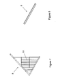
- la figure 1 représente une vue de côté du râtelier selon l'invention,
- la figure 2 représente une vue de face, côté extérieur, du râtelier fixé entre des poteaux d'un bâtiment de ferme, seule la partie intérieure du râtelier étant montée,
- les figures 3 à 8 représentent une vue de côté des différents éléments constituant le râtelier selon l'invention, avant montage du râtelier, la figure 3 représentant une vue de côté du cadre, les figures 4 et 5, une vue de côté des différents types de barres tubulaires coudées situées côté intérieur, la figure 6, une vue de côté de la grille soutenant les bottes côté intérieur, la figure 7, une vue de côté d'un des montants situés côté extérieur, et la figure 8, une vue de côté de la surface soutenant les bottes côté extérieur,
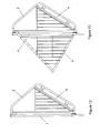
- les figures 9 à 13 représentent une vue de côté du râtelier selon l'invention, au cours des différentes étapes de montage du râtelier par assemblage successif des éléments représentés sur les figures 3 à 8.
- FIG. 1 represents a side view of the rack according to the invention,
- FIG. 2 represents a front view, on the outside, of the rack fixed between posts of a farm building, only the inner part of the rack being mounted,
- Figures 3 to 8 show a side view of the various elements constituting the rack according to the invention, before assembly of the rack, Figure 3 showing a side view of the frame, Figures 4 and 5, a side view of the different types. Figure 6, a side view of the grid supporting the boots on the inner side, Figure 7, a side view of one of the uprights on the outer side, and Figure 8, a view of side of the surface supporting the boots on the outside,
- Figures 9 to 13 show a side view of the rack according to the invention, during the different stages of assembly of the rack by successive assembly of the elements shown in Figures 3 to 8.
Le râtelier selon l'invention, représenté en particulier sur la figure 1, comprend un cadre (1), visible en particulier sur les figures 2 et 3. Ce cadre (1) est constitué de quatre montants sensiblement orthogonaux les uns aux autres. Les deux montants verticaux du cadre se fixent, comme on le verra plus loin, entre les poteaux (7a, 7b) situés à l'entrée d'un bâtiment de ferme, le râtelier selon l'invention remplaçant la barrière permettant l'entrée et la sortie des animaux. Le cadre est muni, à son extrémité inférieure, d'une barre de renfort (10) tubulaire située dans le même plan que le cadre (1). Cette barre de renfort est par exemple fixée à plusieurs endroits du montant inférieur du cadre, par soudure avec une pluralité de tubes, comme représenté sur la figure 2. La distance comprise entre le bas de la barre de renfort (10) et le sol doit être inférieure à la taille moyenne du museau des bovins, de façon à éviter que ces derniers se coincent le museau sous le râtelier. Le cadre (1) comporte également, sur chacun de ses montants horizontaux, une pluralité de plaques (11) munies chacune d'au moins un perçage.The rack according to the invention, represented in particular in FIG. comprises a frame (1), visible in particular in Figures 2 and 3. This frame (1) consists of four substantially orthogonal amounts each other. The two vertical uprights of the frame are fixed, as will be seen further, between the posts (7a, 7b) located at the entrance of a farm building, the rack according to the invention replacing the barrier allowing the entry and the exit of the animals. The frame is provided at its lower end with a reinforcing bar (10) tubular located in the same plane as the frame (1). This reinforcing bar is for example fixed in several places of the amount lower part of the frame, by welding with a plurality of tubes, as shown in Figure 2. The distance between the bottom of the bar reinforcement (10) and the ground should be smaller than the average snout cattle, so that they do not get caught in the muzzle under the rack. The frame (1) also comprises, on each of its amounts horizontal plates, a plurality of plates (11) each provided with at least one drilling.
Le râtelier selon l'invention comprend également une pluralité de barres tubulaires coudées (2, 3) sensiblement en forme d'oreille ou de "C" inversé, contenue chacune dans un plan sensiblement orthogonal au plan du cadre (1). Deux des barres tubulaires coudées, dites barres tubulaires extrêmes (2), sont fixées respectivement à chacune des extrémités du cadre (1) du râtelier, tandis que les autres barres tubulaires coudées, dites barres tubulaires intermédiaires (3), sont fixées sur le cadre en étant réparties entre les barres tubulaires extrêmes (2), comme représenté en particulier sur la figure 2. Le râtelier selon l'invention comporte par exemple trois barres tubulaires intermédiaires (3). Comme représenté en particulier sur les figures 4 et 5, chaque barre tubulaire extrême ou intermédiaire (2, 3) est munie à chacune de ses extrémités d'un crochet (21, 31) muni d'au moins un perçage. Chacun des crochets (21, 31) est destiné à suspendre la barre tubulaire extrême ou intermédiaire (2, 3) sur les montants horizontaux du cadre, comme représenté en particulier sur la figure 10, de façon à ce que l'emplacement de chacun des crochets (21, 31) corresponde à l'emplacement d'une plaque (11) du cadre (1). Chaque barre tubulaire extrême ou intermédiaire (2, 3) est alors fixée au cadre (1) par boulonnage des plaques (11) du cadre (1) avec les crochets (21, 31) correspondants de ladite barre. Les barres tubulaires extrêmes et intermédiaires (2, 3) se fixent toutes du même côté du cadre (1), qui est le côté du râtelier duquel se trouvent les animaux, donc le côté intérieur du bâtiment de ferme.The rack according to the invention also comprises a plurality of bent tubular bars (2, 3) substantially in the form of an ear or "C" inverted, each contained in a plane substantially orthogonal to the plane of the frame (1). Two of the bent tubular bars, called tubular bars extremes (2), are respectively fixed at each end of the frame (1) of the rack, while the other bent tubular bars, called bars intermediate tubes (3) are fixed to the frame and distributed between the extreme tubular bars (2), as shown in particular on the FIG. 2. The rack according to the invention comprises, for example, three bars intermediate tubulars (3). As shown in particular in the figures 4 and 5, each end or intermediate tubular bar (2, 3) is provided with each of its ends with a hook (21, 31) provided with at least one drilling. Each of the hooks (21, 31) is intended to suspend the bar extreme or intermediate tubular (2, 3) on the horizontal uprights of the frame, as shown in particular in Figure 10, so that the location of each of the hooks (21, 31) corresponds to the location of a plate (11) of the frame (1). Each tubular bar extreme or intermediate (2, 3) is then fixed to the frame (1) by bolting plates (11) of the frame (1) with the corresponding hooks (21, 31) of said bar. The extreme and intermediate tubular bars (2, 3) are fixed all on the same side of the frame (1), which is the side of the rack from which find the animals, so the inner side of the farm building.
Chaque barre tubulaire extrême ou intermédiaire (2, 3) est également munie d'une paire de plaques (22, 32) située dans le plan de ladite barre et disposées vers l'intérieur de l'oreille, sur une partie droite de la barre faisant un angle (α) déterminé avec le plan du cadre. Cet angle est par exemple compris entre 20° et 40°, de préférence égal à 30°. Chacune de ces plaques (22, 32) est munie d'au moins un perçage. Par ailleurs, chacune des barres tubulaires extrêmes (2) est munie d'une grille (23), située dans le plan de ladite barre, et constituée de barreaux verticaux par exemple espacés les uns des autres de 10 cm, de façon à éviter que le foin ne tombe de chaque côté du râtelier lorsque les bottes se défont au fur et à mesure que les animaux s'en nourrissent.Each extreme or intermediate tubular bar (2, 3) is also provided with a pair of plates (22, 32) located in the plane of said bar and arranged inward of the ear, on a straight part of the bar an angle (α) determined with the plane of the frame. This angle is for example between 20 ° and 40 °, preferably equal to 30 °. Each of these plates (22, 32) is provided with at least one piercing. Moreover, each of the bars tubes (2) is provided with a grid (23) located in the plane of said bar, and constituted by vertical bars for example spaced the each other by 10 cm, so that hay does not fall from each side of the rack when the boots unravel as the animals feed on it.
Le râtelier selon l'invention comprend également une grille (4), représentée en particulier sur les figures 2 et 6, contenue dans un plan faisant un angle (α) déterminé par rapport au plan du cadre, et destinée à soutenir les bottes côté animaux. Cet angle est par exemple compris entre 20° et 40°, de préférence égal à 30°. Ainsi, la grille (4) du râtelier est disposée parallèlement aux parties droites des barres tubulaires extrêmes et intermédiaires (2, 3) munies d'une paire de plaques (22, 32), à l'intérieur des oreilles, comme cela est représenté en particulier sur la figure 11. La grille (4) du râtelier est constituée de barreaux sensiblement parallèles entre eux dont l'espacement est suffisant pour permettre le passage d'un museau de bovin, mais trop petit pour permettre le passage de sa tête, de façon à éviter que les animaux ne se coincent la tête. L'espacement des barreaux de la grille (4) est donc par exemple de 19 cm. La grille (4) est munie d'une pluralité de paires de plaques (42) disposées sous la grille dont l'emplacement correspond à l'emplacement des paires de plaques (22, 32) des barres tubulaires extrêmes et intermédiaires (2, 3). La grille (4) est fixée à chaque barre tubulaire extrême ou intermédiaire (2, 3) par boulonnage des plaques (42) de la grille (4) avec les plaques (22, 32) desdites barres.The rack according to the invention also comprises a grid (4), shown in particular in FIGS. 2 and 6, contained in a plan angle (α) determined relative to the plane of the frame, and intended to support the animal side boots. This angle is for example between 20 ° and 40 °, preferably 30 °. Thus, the grid (4) of the rack is arranged parallel to the straight portions of the extreme tubular bars and intermediates (2, 3) provided with a pair of plates (22, 32), within the ears, as shown in particular in Figure 11. The grid (4) rack consists of bars substantially parallel to each other, the spacing is sufficient to allow passage of a bovine muzzle, but too small to allow the passage of his head, so as to prevent the animals do not stuck their heads. The spacing of the bars of the grid (4) is for example 19 cm. The grid (4) is provided with a plurality of pairs of plates (42) arranged under the grid whose location corresponds to the location of the pairs of plates (22, 32) of the bars extreme and intermediate tubulars (2, 3). The grid (4) is attached to each Extreme or intermediate tubular bar (2, 3) by bolting plates (42) of the grid (4) with the plates (22, 32) of said bars.
Le râtelier selon l'invention comprend également deux montants extérieurs (5), sensiblement triangulaires, représentés en particulier sur la figure 7, et contenus dans un plan sensiblement orthogonal au plan du cadre (1). Chacun des montants extérieurs (5) est constitué de trois barres boulonnées les unes aux autres, l'une de ces barres étant sensiblement verticale, et une autre faisant un angle (β) déterminé avec la verticale. Cet angle est par exemple compris entre 30° et 60°, de préférence égal à 45°. La troisième barre dépasse du triangle vers le haut, et est munie à son extrémité supérieure d'au moins un perçage. Ce(s) perçage(s) permet(tent) la fixation de chacun des montants extérieurs (5) par boulonnage sur une plaque (24) fixée en haut de chaque barre tubulaire extrême (2). Chacun des montants extérieurs (5) est fixé du côté opposé aux animaux, donc du côté extérieur du bâtiment de ferme. Chacun des montants extérieurs (5) est muni d'une grille (53) située dans le plan dudit montant, constituée de barreaux verticaux par exemple espacés les uns des autres de 10 cm, de façon à éviter que le foin ne tombe de chaque côté du râtelier lorsque les bottes se défont au fur et à mesure que les animaux s'en nourrissent.The rack according to the invention also comprises two uprights (5), substantially triangular, represented in particular on the FIG. 7, and contained in a plane substantially orthogonal to the plane of the frame (1). Each of the outer posts (5) consists of three bars bolted to each other, one of these bars being substantially vertical, and another making an angle (β) determined with the vertical. This angle is for example between 30 ° and 60 °, preferably equal to 45 °. The third bar protrudes from the triangle upwards, and is provided at its end greater than at least one piercing. This piercing (s) allows (the) fixation of each of the outer posts (5) by bolting onto a plate (24) fixed at the top of each extreme tubular bar (2). Each of the amounts (5) is fixed on the opposite side to the animals, therefore on the outer side of the farm building. Each of the outer pillars (5) is provided with a grid (53) located in the plane of said upright, consisting of vertical bars by example spaced from each other by 10 cm, to prevent hay does not fall on either side of the rack when the boots break down as and when as the animals feed on it.
Le râtelier selon l'invention comprend enfin une surface (6), représentée en particulier sur la figure 8, contenue dans un plan faisant un angle (β) déterminé par rapport au plan du cadre, et destinée à soutenir les bottes côté extérieur. Cet angle est par exemple compris entre 30° et 60°, de préférence égal à 45°. Ainsi, la surface (6) est disposée parallèlement aux barres des montants extérieurs (5) faisant un angle (β) déterminé par rapport au plan du cadre, comme cela est représenté en particulier sur la figure 1. La surface est de préférence en tôle et munie d'une pluralité de nervures destinées à éviter un effet "ventouse" lorsque les bottes, qui sont posées sur cette surface (6) et sur la grille (4), sont légèrement humides. La surface (6) est munie d'au moins trois rebords sur ses côtés, qui viennent en contact respectivement avec les montants latéraux (5) et avec le montant horizontal inférieur du cadre (1 ), sur lesquels ils sont fixés par boulonnage. Pour faciliter la mise en place de la surface (6) contre le montant horizontal inférieur du cadre (1) et pour que le râtelier soit plus solide, le rebord de la surface (6) se fixant sur ledit montant du cadre comporte un angle droit permettant de prendre appui sur deux faces de ce dit montant, comme représenté en particulier sur la figure 1. L'espace formé entre les triangles constitués par les montants extérieurs (5) avec la surface (6) et le cadre (1) est libre pour permettre un chargement des bottes par l'extérieur du râtelier.The rack according to the invention finally comprises a surface (6), shown in particular in Figure 8, contained in a plane making a angle (β) determined with respect to the plane of the frame, and intended to support the boots outside. This angle is for example between 30 ° and 60 °, preferably equal to 45 °. Thus, the surface (6) is arranged parallel to the bars of the external uprights (5) making an angle (β) determined relative to to the plane of the frame, as shown in particular in FIG. surface is preferably sheet metal and provided with a plurality of ribs intended to avoid a "sucker" effect when the boots, which are placed on this surface (6) and on the grid (4) are slightly moist. The surface (6) is provided with at least three flanges on its sides, which come into contact respectively with the lateral uprights (5) and with the horizontal upright lower frame (1), on which they are fixed by bolting. To facilitate placing the surface (6) against the lower horizontal post of the frame (1) and for the rack to be stronger, the edge of the surface (6) fixing on said frame member has a right angle allowing take support on two sides of this said amount, as represented in particular in Figure 1. The space formed between the triangles constituted by the outer uprights (5) with the surface (6) and the frame (1) are free for allow the boots to be loaded from outside the rack.
En effet, le râtelier étant amené à supporter une masse importante (jusqu'à environ 2 tonnes), il est important que sa structure soit solide. Le râtelier est donc métallique. Ainsi, l'ensemble des éléments (1 à 6) constituant le râtelier, ainsi que les éléments de fixation du râtelier sur les poteaux (7a, 7b) du bâtiment de ferme, doivent être suffisamment résistants pour supporter plusieurs tonnes. Les grilles (23, 53) des barres tubulaires extrêmes (2) et des montants extérieurs (5) sont par exemple fixés par soudage respectivement aux barres tubulaires extrêmes (2) et aux montants extérieurs (5).Indeed, the rack being made to support a large mass (up to about 2 tons), it is important that its structure is solid. The rack is therefore metallic. Thus, all the elements (1 to 6) the rack and the fastening elements of the rack on the posts (7a, 7b) of the farm building must be strong enough to support several tons. The grids (23, 53) of the tubular bars extremes (2) and external amounts (5) are for example fixed by welding respectively to the extreme tubular bars (2) and to the studs outside (5).
Comme cela est représenté sur les figures 9 à 13 illustrant les différentes étapes de montage du râtelier, la première étape du montage (figure 9) consiste à fixer le cadre (1) entre les poteaux (7a, 7b) du bâtiment de ferme. Dans une deuxième étape (figure 10), les barres tubulaires intermédiaires (3) sont fixées au cadre (1). Dans une troisième étape (figure 11), la grille (4) est fixée aux barres tubulaires intermédiaires (3).Dans une quatrième étape, (figure 12), les barres tubulaires extrêmes (2) sont fixées au cadre (1) et à la grille (4). Dans une cinquième étape (figure 13), le montant extérieur (5) est fixé aux barres tubulaires extrêmes (2). Dans une sixième étape (figure 1), la surface (6) est fixée aux montants extérieurs (5) et au cadre (1).As shown in Figures 9 to 13 illustrating the different stages of assembly of the rack, the first stage of assembly (Figure 9) is to fix the frame (1) between the poles (7a, 7b) of the building of farm. In a second step (Figure 10), the tubular bars intermediaries (3) are attached to the frame (1). In a third step (figure 11), the grid (4) is fixed to the intermediate tubular bars (3) .In a fourth step, (FIG. 12), the end tubular bars (2) are fixed at frame (1) and to the grid (4). In a fifth step (Figure 13), the amount outside (5) is fixed to the end tubular bars (2). In a sixth stage (FIG. 1), the surface (6) is fixed to the external uprights (5) and to the frame (1).
Une fois le montage terminé, l'éleveur dispose plusieurs bottes de foin sur la grille (4) et la surface (6) en les insérant depuis l'extérieur de la ferme. Ainsi, sa sécurité est parfaitement assurée puisqu'il n'a pas à pénétrer dans la stabulation. Les animaux se nourrissent en passant leur museau entre les barreaux de la grille (4) du râtelier.Once the assembly is finished, the farmer has several bunches of hay on the grid (4) and the surface (6) by inserting them from the outside of the farm. Thus, its security is perfectly ensured since it does not have to penetrate stabling. The animals feed by passing their muzzle between bars of the grid (4) of the rack.
La fixation du cadre (1) du râtelier selon l'invention entre des poteaux (7a, 7b) d'un bâtiment de ferme va maintenant être décrite. Le râtelier étant disposé à la place d'une barrière, il doit pouvoir être ouvert pour laisser sortir les animaux et/ou cureter les stabulations. Pour ce faire, le cadre (1) du râtelier est fixé de façon à pouvoir pivoter autour d'un des poteaux (7a, 7b) et à pouvoir être maintenu en position fermée sans que les animaux puissent sortir sans intervention de l'éleveur. Le cadre (1) du râtelier est symétrique de façon à ce que l'éleveur puisse choisir dans quel sens le cadre va s'ouvrir, c'est-à-dire autour de quel poteau il va pivoter.Fixing the frame (1) of the rack according to the invention between posts (7a, 7b) of a farm building will now be described. The rack being placed in place of a barrier, it must be open to let out animals and / or curettage stabulations. To do this, the framework (1) of rack is fixed so as to be pivotable about one of the posts (7a, 7b) and able to be kept in a closed position without the animals being able to go out without intervention of the breeder. The frame (1) of the rack is symmetrical so that the farmer can choose in which direction the frame will open, that is to say around which pole he will rotate.
Le cadre (1) est muni, à proximité de l'extrémité inférieure de chacun de ses montants verticaux, d'un élément en saillie (12a, 12b) sensiblement horizontal, disposé vers l'extérieur du cadre, et renforcé par une plaque triangulaire (13a, 13b) servant d'équerre. Un ergot (14) sensiblement vertical est soudé en dessous de chaque élément en saillie (12a, 12b). Cet ergot (12) va servir de pivot du côté du poteau de pivotement (7b) en étant inséré dans un perçage réalisé dans une plaque (74) sensiblement horizontale fixée sur le poteau de pivotement (7b), comme représenté sur la figure 2. L'ergot situé de l'autre côté du cadre est scié. Lorsque le râtelier est en position fermée, l'élément en saillie (12a) situé à l'opposé du poteau de pivotement (7b) est inséré entre deux premières plaques (72, 73) munies chacune d'un perçage traversé par une première tige de blocage (71) amovible sensiblement verticale. Cette première tige de blocage (71) permet de retenir le râtelier lorsque l'élément en saillie (12a) situé à l'opposé du poteau de pivotement (7b) est situé entre le poteau (7a) opposé au poteau de pivotement (7b) et ladite première tige de blocage (71). Il suffit de retirer cette première tige de blocage (71) des perçages pour libérer ledit élément en saillie (12a).The frame (1) is provided near the lower end of each of its vertical uprights, a protruding element (12a, 12b) substantially horizontal, arranged towards the outside of the frame, and reinforced by a plate triangular (13a, 13b) serving as a square. A substantially vertical pin (14) is welded below each projecting element (12a, 12b). This pin (12) will serve as a pivot on the side of the pivot post (7b) while being inserted in a hole made in a plate (74) substantially horizontal fixed on the pivot post (7b), as shown in Figure 2. The ergot located on the other side of the frame is sawn. When the rack is in the closed position, the projecting element (12a) situated opposite the pivoting post (7b) is inserted between two first plates (72, 73) each provided with a bore traversed by a first substantially removable locking rod (71) vertical. This first locking rod (71) makes it possible to retain the rack when the protruding member (12a) located opposite the pivot post (7b) is located between the post (7a) opposite the pivot post (7b) and said first blocking rod (71). Just remove this first rod of locking (71) bores to release said projecting member (12a).
Le cadre (1) est également muni, sur chacun de ses montants
verticaux, d'au moins deux perçages (respectivement 15a, 16a et 15b, 16b),
sensiblement horizontaux situés dans le plan du cadre. Un de ces perçages
(15a, 15b) est situé à une hauteur facilement accessible par une personne
de taille moyenne, l'autre perçage (16a, 16b) étant situé à proximité de
l'extrémité supérieure du montant vertical correspondant du cadre (1). Le
perçage (16a, 16b) le plus élevé est utilisé pour le pivotement du râtelier
tandis que l'autre (15a, 15b) est utilisé pour bloquer le râtelier en position
fermée. Une tige (150, 160) est fixée dans chacun des perçages utilisés
(respectivement 15a et 16b dans le cas de la figure 2, le poteau 7b étant
désigné comme le poteau de pivotement) par des boulons, cette tige (150,
160) se terminant par une boucle. Chacune des boucles est insérée entre
deux plaques (respectivement 77a, 78a et 77b, 78b), appelées
respectivement deuxièmes plaques (77a, 78a) et troisièmes plaques (77b,
78b), munies d'un perçage. Une deuxième et une troisième tiges de blocage
(respectivement 75 et 76) amovibles sensiblement verticales traversent ces
perçages ainsi que la boucle des tiges correspondantes (respectivement 150
et 160). En enlevant la deuxième tige de blocage (75), la boucle située à
l'opposé du poteau de pivotement (7b) est libérée et le râtelier peut pivoter
autour du poteau de pivotement (7b), la troisième tige de blocage (76)
servant alors de pivot.The frame (1) is also provided, on each of its amounts
vertical, of at least two holes (respectively 15a, 16a and 15b, 16b),
substantially horizontal in the plane of the frame. One of these holes
(15a, 15b) is located at a height easily accessible by a person
of medium size, the other piercing (16a, 16b) being located near
the upper end of the corresponding vertical upright of the frame (1). The
highest hole (16a, 16b) is used for pivoting of the rack
while the other (15a, 15b) is used to lock the rack in position
closed. A rod (150, 160) is fixed in each of the bores used
(respectively 15a and 16b in the case of Figure 2, the
Enfin, pour renforcer la structure lors du pivotement, un tendeur (8) est tendu entre un point situé à proximité de l'extrémité supérieure du poteau de pivotement (7b) et l'extrémité supérieure du montant vertical du cadre (1) opposée au poteau de pivotement (7b), comme cela est représenté sur la figure 2. Ainsi, le râtelier peut pivoter autour du poteau de pivotement (7b) en étant maintenu par trois points de pivotement.Finally, to reinforce the structure during pivoting, a tensioner (8) is stretched between a point near the upper end of the pivoting (7b) and the upper end of the upright of the frame (1) opposite to the pivot post (7b), as shown on the FIG. 2. Thus, the rack can pivot about the pivot pole (7b) in being held by three pivot points.
Le montage du râtelier selon l'invention est relativement simple. Le fait que le râtelier soit livré en plusieurs éléments permet de le galvaniser avant montage, ce qui permet une plus longue tenue que de la peinture. Il n'existe en effet pas de bains de galvanisation de volume suffisamment important pour contenir un râtelier monté. De plus, le transport est facilité puisque les différents éléments du râtelier peuvent être emboítés pour obtenir un volume inférieur à celui du râtelier monté, ce qui présente également l'avantage de permettre le transport de plusieurs râteliers en un seul voyage.The assembly of the rack according to the invention is relatively simple. The fact that the rack is delivered in several elements allows to galvanize before assembly, which allows a longer hold than paint. There is indeed no galvanizing baths of sufficiently large volume to hold a mounted rack. In addition, transportation is facilitated since different elements of the rack can be nested to obtain a volume lower than that of the mounted rack, which also has the advantage of allow the transport of several racks in one trip.
La longueur du râtelier est par exemple, mais de façon non limitative, de 5 m ou de 6 m, ce qui correspond à la distance standard de l'entrée des bâtiments de ferme. Ainsi, le râtelier permet d'accueillir jusqu'à 4 bottes rondes de taille standard ou deux bottes rectangulaires de taille standard. La hauteur du râtelier est par exemple d'environ 2,5 m, réalisant ainsi une véritable barrière pour les bovins. Enfin, l'épaisseur du râtelier est par exemple de 2,5 m, une partie étant située à l'extérieur du bâtiment ce qui permet de peu empiéter sur l'espace des animaux. On peut prévoir d'installer un toit au-dessus du râtelier pour protéger le fourrage contre les intempéries.The length of the rack is for example, but without limitation, 5 m or 6 m, which corresponds to the standard distance from the entrance of farm buildings. Thus, the rack can accommodate up to 4 boots standard size round or two standard size rectangular boots. The rack height is for example about 2.5 m, thereby achieving a real barrier for cattle. Finally, the thickness of the rack is example of 2.5 m, part of which is located outside the building which allows little encroachment on the space of the animals. We can plan to install a roof over the rack to protect the forage from the elements.
Il doit être évident, pour les personnes versées dans l'art, que la présente invention permet des modes de réalisation sous de nombreuses autres formes spécifiques sans l'éloigner du domaine d'application de l'invention comme revendiqué. En particulier, le cadre (1) peut être fixé aux poteaux (7a, 7b) du bâtiment de ferme par tout autre moyen de fixation suffisamment résistant pour permettre l'ouverture du râtelier comme une barrière par pivotement autour d'un axe vertical. Par conséquent, les présents modes de réalisation doivent être considérés à titre d'illustration, mais peuvent être modifiés dans le domaine défini par la portée des revendications jointes, et l'invention ne doit pas être limitée aux détails donnés ci-dessus.It should be obvious to those skilled in the art that the present invention allows embodiments under many other specific forms without distancing it from the scope of the invention as claimed. In particular, the framework (1) can be fixed at posts (7a, 7b) of the farm building by any other means of attachment sufficiently strong to allow the opening of the rack as a barrier by pivoting about a vertical axis. Therefore, present embodiments should be considered by way of illustration, but may be modified in the field defined by the scope of the attached claims, and the invention should not be limited to given above.
Claims (14)
Applications Claiming Priority (2)
| Application Number | Priority Date | Filing Date | Title |
|---|---|---|---|
| FR0313319 | 2003-11-14 | ||
| FR0313319A FR2862186B1 (en) | 2003-11-14 | 2003-11-14 | RACK |
Publications (3)
| Publication Number | Publication Date |
|---|---|
| EP1530897A2 true EP1530897A2 (en) | 2005-05-18 |
| EP1530897A3 EP1530897A3 (en) | 2005-06-15 |
| EP1530897B1 EP1530897B1 (en) | 2006-09-13 |
Family
ID=34429987
Family Applications (1)
| Application Number | Title | Priority Date | Filing Date |
|---|---|---|---|
| EP04292686A Active EP1530897B1 (en) | 2003-11-14 | 2004-11-12 | Rack for animal feed |
Country Status (4)
| Country | Link |
|---|---|
| EP (1) | EP1530897B1 (en) |
| AT (1) | ATE339096T1 (en) |
| DE (1) | DE602004002365D1 (en) |
| FR (1) | FR2862186B1 (en) |
Cited By (1)
| Publication number | Priority date | Publication date | Assignee | Title |
|---|---|---|---|---|
| CN113974893A (en) * | 2021-10-25 | 2022-01-28 | 江苏美迪森生物医药有限公司 | Restraint device for mouse experiments |
Citations (5)
| Publication number | Priority date | Publication date | Assignee | Title |
|---|---|---|---|---|
| US4753194A (en) * | 1985-06-10 | 1988-06-28 | N.V. Nederlandsche Apparatenfabriek Nedap | Cattle feeding station |
| FR2628288A1 (en) * | 1988-03-11 | 1989-09-15 | Thebault Ets Robert | Separating barrier e.g. for pig fattening housing - has slotted posts which fit into troughs and receive panels forming barrier |
| GB2369033A (en) * | 2000-10-13 | 2002-05-22 | Peter William Allen | Apparatus for supplying animal feed |
| US20020195060A1 (en) * | 2001-06-25 | 2002-12-26 | Dollahan Meredith S. | Feed trough |
| US20030029386A1 (en) * | 2001-08-10 | 2003-02-13 | Sprik Dale R. | Livestock feeder |
-
2003
- 2003-11-14 FR FR0313319A patent/FR2862186B1/en not_active Expired - Lifetime
-
2004
- 2004-11-12 EP EP04292686A patent/EP1530897B1/en active Active
- 2004-11-12 AT AT04292686T patent/ATE339096T1/en not_active IP Right Cessation
- 2004-11-12 DE DE602004002365T patent/DE602004002365D1/en active Active
Patent Citations (5)
| Publication number | Priority date | Publication date | Assignee | Title |
|---|---|---|---|---|
| US4753194A (en) * | 1985-06-10 | 1988-06-28 | N.V. Nederlandsche Apparatenfabriek Nedap | Cattle feeding station |
| FR2628288A1 (en) * | 1988-03-11 | 1989-09-15 | Thebault Ets Robert | Separating barrier e.g. for pig fattening housing - has slotted posts which fit into troughs and receive panels forming barrier |
| GB2369033A (en) * | 2000-10-13 | 2002-05-22 | Peter William Allen | Apparatus for supplying animal feed |
| US20020195060A1 (en) * | 2001-06-25 | 2002-12-26 | Dollahan Meredith S. | Feed trough |
| US20030029386A1 (en) * | 2001-08-10 | 2003-02-13 | Sprik Dale R. | Livestock feeder |
Cited By (1)
| Publication number | Priority date | Publication date | Assignee | Title |
|---|---|---|---|---|
| CN113974893A (en) * | 2021-10-25 | 2022-01-28 | 江苏美迪森生物医药有限公司 | Restraint device for mouse experiments |
Also Published As
| Publication number | Publication date |
|---|---|
| ATE339096T1 (en) | 2006-10-15 |
| EP1530897B1 (en) | 2006-09-13 |
| FR2862186B1 (en) | 2006-03-10 |
| FR2862186A1 (en) | 2005-05-20 |
| DE602004002365D1 (en) | 2006-10-26 |
| EP1530897A3 (en) | 2005-06-15 |
Similar Documents
| Publication | Publication Date | Title |
|---|---|---|
| US8061076B2 (en) | Portable large animal trap and method | |
| US8919286B2 (en) | Modular baled hay feeding system and method for livestock | |
| FR2550918A1 (en) | Lobster-pot system for crustacea, in the form of a frustum of a pyramid with square bases, which traps a large number of fish and is easy to transport and to store. | |
| EP1530897B1 (en) | Rack for animal feed | |
| EP3116310B1 (en) | Device for protection against terrestrial gastropods | |
| EP0681783A1 (en) | Cage for the culture of bivalves, especially of oysters | |
| US9345229B2 (en) | Livestock feeding rack | |
| FR2611429A1 (en) | Improvement of milking installations | |
| FR2460614A1 (en) | Feeding trough for young animals - has trough within cage and access by passing head between bars adjusted to exclude adult animals | |
| FR2890530A1 (en) | Feeder for domesticated animals, especially horses, comprises frame supporting suspended net and covering lid | |
| FR2973986A1 (en) | COLLECTIVE HOUSING FOR THE GAVING OF PALMIPEDES | |
| KR200466135Y1 (en) | Hay suppling device for cattle shed | |
| JPH0711589Y2 (en) | Wildlife capture fence | |
| FR2979799A1 (en) | Barrier e.g. swedish stanchion, for use in breeding enclosure for e.g. horned sheep to assure e.g. veterinary care, has application beam moved until release position from top to bottom so as to partially release access to side clearance | |
| EP2962560B1 (en) | Fish pond anti-predation device | |
| FR2651961A1 (en) | Hive support device with a floor and pollen hatch which are removable | |
| FR3007939A1 (en) | RATELIER FOR EQUIDES | |
| FR2867215A3 (en) | Compound fence for e.g. swimming pool, has latch assemblies placed on door jambs in respective positions corresponding to locking panels, and chassis fixed between two lateral jambs inserted at lower end on base cover by angle bracket | |
| FR2811512A1 (en) | Feeding stall, for animals, is fitted with door, which pivots on horizontal pivot axis and carries counterbalance weight, which moves relative to pivot axis, to provide closing force, when required. | |
| CA3178530A1 (en) | Rehabilitation/release cage, nest boxes and release process for eastern grey squirrels (sciurus carolinensis) | |
| FR2955456A1 (en) | Living animals e.g. pigeons, catching method for e.g. controlling population of animals in agricultural zone, involves releasing animal that is retained in cage, after predetermined time period | |
| FR3042947A1 (en) | ROCKING INSECT TRAP AND METHOD OF IMPLEMENTING THE SAME | |
| FR2964996A1 (en) | Balustrade for use on structure of e.g. industrial building, to protect intervenor in height on inclined or flat roof, has adhesion point adhered to link to maintain balustrade in suspended state in support configuration on structure | |
| FR2848384A1 (en) | Animal capturing trap, has cage in form of rectangular fit with two frames where frames are formed at extremities of trap and central frame articulated around middle point of traps lower panel | |
| FR3024016A1 (en) | MODULAR DEVICE FOR COLLECTIVE CAGE OF POULTRY, IN PARTICULAR PALMIPEDES |
Legal Events
| Date | Code | Title | Description |
|---|---|---|---|
| PUAI | Public reference made under article 153(3) epc to a published international application that has entered the european phase |
Free format text: ORIGINAL CODE: 0009012 |
|
| PUAL | Search report despatched |
Free format text: ORIGINAL CODE: 0009013 |
|
| AK | Designated contracting states |
Kind code of ref document: A2 Designated state(s): AT BE BG CH CY CZ DE DK EE ES FI FR GB GR HU IE IS IT LI LU MC NL PL PT RO SE SI SK TR |
|
| AX | Request for extension of the european patent |
Extension state: AL HR LT LV MK YU |
|
| AK | Designated contracting states |
Kind code of ref document: A3 Designated state(s): AT BE BG CH CY CZ DE DK EE ES FI FR GB GR HU IE IS IT LI LU MC NL PL PT RO SE SI SK TR |
|
| AX | Request for extension of the european patent |
Extension state: AL HR LT LV MK YU |
|
| 17P | Request for examination filed |
Effective date: 20051020 |
|
| AKX | Designation fees paid |
Designated state(s): AT BE BG CH CY CZ DE DK EE ES FI FR GB GR HU IE IS IT LI LU MC NL PL PT RO SE SI SK TR |
|
| GRAP | Despatch of communication of intention to grant a patent |
Free format text: ORIGINAL CODE: EPIDOSNIGR1 |
|
| GRAS | Grant fee paid |
Free format text: ORIGINAL CODE: EPIDOSNIGR3 |
|
| GRAA | (expected) grant |
Free format text: ORIGINAL CODE: 0009210 |
|
| AK | Designated contracting states |
Kind code of ref document: B1 Designated state(s): AT BE BG CH CY CZ DE DK EE ES FI FR GB GR HU IE IS IT LI LU MC NL PL PT RO SE SI SK TR |
|
| PG25 | Lapsed in a contracting state [announced via postgrant information from national office to epo] |
Ref country code: IT Free format text: LAPSE BECAUSE OF FAILURE TO SUBMIT A TRANSLATION OF THE DESCRIPTION OR TO PAY THE FEE WITHIN THE PRESCRIBED TIME-LIMIT;WARNING: LAPSES OF ITALIAN PATENTS WITH EFFECTIVE DATE BEFORE 2007 MAY HAVE OCCURRED AT ANY TIME BEFORE 2007. THE CORRECT EFFECTIVE DATE MAY BE DIFFERENT FROM THE ONE RECORDED. Effective date: 20060913 Ref country code: FI Free format text: LAPSE BECAUSE OF FAILURE TO SUBMIT A TRANSLATION OF THE DESCRIPTION OR TO PAY THE FEE WITHIN THE PRESCRIBED TIME-LIMIT Effective date: 20060913 Ref country code: SI Free format text: LAPSE BECAUSE OF FAILURE TO SUBMIT A TRANSLATION OF THE DESCRIPTION OR TO PAY THE FEE WITHIN THE PRESCRIBED TIME-LIMIT Effective date: 20060913 Ref country code: AT Free format text: LAPSE BECAUSE OF FAILURE TO SUBMIT A TRANSLATION OF THE DESCRIPTION OR TO PAY THE FEE WITHIN THE PRESCRIBED TIME-LIMIT Effective date: 20060913 Ref country code: CZ Free format text: LAPSE BECAUSE OF FAILURE TO SUBMIT A TRANSLATION OF THE DESCRIPTION OR TO PAY THE FEE WITHIN THE PRESCRIBED TIME-LIMIT Effective date: 20060913 Ref country code: SK Free format text: LAPSE BECAUSE OF FAILURE TO SUBMIT A TRANSLATION OF THE DESCRIPTION OR TO PAY THE FEE WITHIN THE PRESCRIBED TIME-LIMIT Effective date: 20060913 Ref country code: NL Free format text: LAPSE BECAUSE OF FAILURE TO SUBMIT A TRANSLATION OF THE DESCRIPTION OR TO PAY THE FEE WITHIN THE PRESCRIBED TIME-LIMIT Effective date: 20060913 Ref country code: GB Free format text: LAPSE BECAUSE OF FAILURE TO SUBMIT A TRANSLATION OF THE DESCRIPTION OR TO PAY THE FEE WITHIN THE PRESCRIBED TIME-LIMIT Effective date: 20060913 Ref country code: PL Free format text: LAPSE BECAUSE OF FAILURE TO SUBMIT A TRANSLATION OF THE DESCRIPTION OR TO PAY THE FEE WITHIN THE PRESCRIBED TIME-LIMIT Effective date: 20060913 Ref country code: RO Free format text: LAPSE BECAUSE OF FAILURE TO SUBMIT A TRANSLATION OF THE DESCRIPTION OR TO PAY THE FEE WITHIN THE PRESCRIBED TIME-LIMIT Effective date: 20060913 Ref country code: IE Free format text: LAPSE BECAUSE OF FAILURE TO SUBMIT A TRANSLATION OF THE DESCRIPTION OR TO PAY THE FEE WITHIN THE PRESCRIBED TIME-LIMIT Effective date: 20060913 |
|
| REG | Reference to a national code |
Ref country code: GB Ref legal event code: FG4D Free format text: NOT ENGLISH |
|
| REG | Reference to a national code |
Ref country code: CH Ref legal event code: EP |
|
| REG | Reference to a national code |
Ref country code: IE Ref legal event code: FG4D Free format text: LANGUAGE OF EP DOCUMENT: FRENCH |
|
| REF | Corresponds to: |
Ref document number: 602004002365 Country of ref document: DE Date of ref document: 20061026 Kind code of ref document: P |
|
| PG25 | Lapsed in a contracting state [announced via postgrant information from national office to epo] |
Ref country code: BE Free format text: LAPSE BECAUSE OF NON-PAYMENT OF DUE FEES Effective date: 20061130 Ref country code: MC Free format text: LAPSE BECAUSE OF NON-PAYMENT OF DUE FEES Effective date: 20061130 |
|
| PG25 | Lapsed in a contracting state [announced via postgrant information from national office to epo] |
Ref country code: SE Free format text: LAPSE BECAUSE OF FAILURE TO SUBMIT A TRANSLATION OF THE DESCRIPTION OR TO PAY THE FEE WITHIN THE PRESCRIBED TIME-LIMIT Effective date: 20061213 Ref country code: DK Free format text: LAPSE BECAUSE OF FAILURE TO SUBMIT A TRANSLATION OF THE DESCRIPTION OR TO PAY THE FEE WITHIN THE PRESCRIBED TIME-LIMIT Effective date: 20061213 Ref country code: BG Free format text: LAPSE BECAUSE OF FAILURE TO SUBMIT A TRANSLATION OF THE DESCRIPTION OR TO PAY THE FEE WITHIN THE PRESCRIBED TIME-LIMIT Effective date: 20061213 |
|
| PG25 | Lapsed in a contracting state [announced via postgrant information from national office to epo] |
Ref country code: DE Free format text: LAPSE BECAUSE OF FAILURE TO SUBMIT A TRANSLATION OF THE DESCRIPTION OR TO PAY THE FEE WITHIN THE PRESCRIBED TIME-LIMIT Effective date: 20061214 |
|
| PG25 | Lapsed in a contracting state [announced via postgrant information from national office to epo] |
Ref country code: ES Free format text: LAPSE BECAUSE OF FAILURE TO SUBMIT A TRANSLATION OF THE DESCRIPTION OR TO PAY THE FEE WITHIN THE PRESCRIBED TIME-LIMIT Effective date: 20061224 |
|
| PG25 | Lapsed in a contracting state [announced via postgrant information from national office to epo] |
Ref country code: IS Free format text: LAPSE BECAUSE OF FAILURE TO SUBMIT A TRANSLATION OF THE DESCRIPTION OR TO PAY THE FEE WITHIN THE PRESCRIBED TIME-LIMIT Effective date: 20070113 |
|
| PG25 | Lapsed in a contracting state [announced via postgrant information from national office to epo] |
Ref country code: PT Free format text: LAPSE BECAUSE OF FAILURE TO SUBMIT A TRANSLATION OF THE DESCRIPTION OR TO PAY THE FEE WITHIN THE PRESCRIBED TIME-LIMIT Effective date: 20070226 |
|
| NLV1 | Nl: lapsed or annulled due to failure to fulfill the requirements of art. 29p and 29m of the patents act | ||
| GBV | Gb: ep patent (uk) treated as always having been void in accordance with gb section 77(7)/1977 [no translation filed] |
Effective date: 20060913 |
|
| REG | Reference to a national code |
Ref country code: IE Ref legal event code: FD4D |
|
| PLBE | No opposition filed within time limit |
Free format text: ORIGINAL CODE: 0009261 |
|
| STAA | Information on the status of an ep patent application or granted ep patent |
Free format text: STATUS: NO OPPOSITION FILED WITHIN TIME LIMIT |
|
| REG | Reference to a national code |
Ref country code: FR Ref legal event code: ST Effective date: 20070731 |
|
| 26N | No opposition filed |
Effective date: 20070614 |
|
| BERE | Be: lapsed |
Owner name: DESSOLIERE, THIERRY Effective date: 20061130 |
|
| PG25 | Lapsed in a contracting state [announced via postgrant information from national office to epo] |
Ref country code: GR Free format text: LAPSE BECAUSE OF FAILURE TO SUBMIT A TRANSLATION OF THE DESCRIPTION OR TO PAY THE FEE WITHIN THE PRESCRIBED TIME-LIMIT Effective date: 20061214 Ref country code: FR Free format text: LAPSE BECAUSE OF NON-PAYMENT OF DUE FEES Effective date: 20061130 |
|
| PG25 | Lapsed in a contracting state [announced via postgrant information from national office to epo] |
Ref country code: EE Free format text: LAPSE BECAUSE OF FAILURE TO SUBMIT A TRANSLATION OF THE DESCRIPTION OR TO PAY THE FEE WITHIN THE PRESCRIBED TIME-LIMIT Effective date: 20060913 |
|
| PG25 | Lapsed in a contracting state [announced via postgrant information from national office to epo] |
Ref country code: HU Free format text: LAPSE BECAUSE OF FAILURE TO SUBMIT A TRANSLATION OF THE DESCRIPTION OR TO PAY THE FEE WITHIN THE PRESCRIBED TIME-LIMIT Effective date: 20070314 Ref country code: LU Free format text: LAPSE BECAUSE OF NON-PAYMENT OF DUE FEES Effective date: 20061112 Ref country code: TR Free format text: LAPSE BECAUSE OF FAILURE TO SUBMIT A TRANSLATION OF THE DESCRIPTION OR TO PAY THE FEE WITHIN THE PRESCRIBED TIME-LIMIT Effective date: 20060913 |
|
| PG25 | Lapsed in a contracting state [announced via postgrant information from national office to epo] |
Ref country code: CY Free format text: LAPSE BECAUSE OF FAILURE TO SUBMIT A TRANSLATION OF THE DESCRIPTION OR TO PAY THE FEE WITHIN THE PRESCRIBED TIME-LIMIT Effective date: 20060913 |
|
| REG | Reference to a national code |
Ref country code: CH Ref legal event code: PL |
|
| PG25 | Lapsed in a contracting state [announced via postgrant information from national office to epo] |
Ref country code: LI Free format text: LAPSE BECAUSE OF NON-PAYMENT OF DUE FEES Effective date: 20081130 Ref country code: CH Free format text: LAPSE BECAUSE OF NON-PAYMENT OF DUE FEES Effective date: 20081130 |