EP1530706B1 - Linearaktuator - Google Patents
Linearaktuator Download PDFInfo
- Publication number
- EP1530706B1 EP1530706B1 EP03771540A EP03771540A EP1530706B1 EP 1530706 B1 EP1530706 B1 EP 1530706B1 EP 03771540 A EP03771540 A EP 03771540A EP 03771540 A EP03771540 A EP 03771540A EP 1530706 B1 EP1530706 B1 EP 1530706B1
- Authority
- EP
- European Patent Office
- Prior art keywords
- base
- linear actuator
- magnet
- keeper
- longitudinal axis
- Prior art date
- Legal status (The legal status is an assumption and is not a legal conclusion. Google has not performed a legal analysis and makes no representation as to the accuracy of the status listed.)
- Expired - Lifetime
Links
- 239000000463 material Substances 0.000 claims description 22
- 238000005452 bending Methods 0.000 claims description 7
- 230000005294 ferromagnetic effect Effects 0.000 claims description 6
- 238000010276 construction Methods 0.000 claims description 5
- 238000004519 manufacturing process Methods 0.000 claims description 5
- 238000003698 laser cutting Methods 0.000 claims description 2
- 238000000034 method Methods 0.000 claims description 2
- 230000004907 flux Effects 0.000 description 20
- 230000007246 mechanism Effects 0.000 description 10
- 239000003302 ferromagnetic material Substances 0.000 description 5
- 230000005291 magnetic effect Effects 0.000 description 5
- 238000013016 damping Methods 0.000 description 3
- 239000002184 metal Substances 0.000 description 3
- 229910000831 Steel Inorganic materials 0.000 description 2
- 239000004020 conductor Substances 0.000 description 2
- 230000003116 impacting effect Effects 0.000 description 2
- 230000010355 oscillation Effects 0.000 description 2
- 239000010959 steel Substances 0.000 description 2
- 229910000975 Carbon steel Inorganic materials 0.000 description 1
- 230000001133 acceleration Effects 0.000 description 1
- 239000000853 adhesive Substances 0.000 description 1
- 230000001070 adhesive effect Effects 0.000 description 1
- 230000004075 alteration Effects 0.000 description 1
- 239000010962 carbon steel Substances 0.000 description 1
- 238000005266 casting Methods 0.000 description 1
- 230000000694 effects Effects 0.000 description 1
- 239000012530 fluid Substances 0.000 description 1
- 230000001788 irregular Effects 0.000 description 1
- 238000003754 machining Methods 0.000 description 1
- 238000012986 modification Methods 0.000 description 1
- 230000004048 modification Effects 0.000 description 1
- 230000000135 prohibitive effect Effects 0.000 description 1
- 230000004044 response Effects 0.000 description 1
- 229920006395 saturated elastomer Polymers 0.000 description 1
- 230000035945 sensitivity Effects 0.000 description 1
- 239000007787 solid Substances 0.000 description 1
- 239000013598 vector Substances 0.000 description 1
Images

Classifications
-
- G—PHYSICS
- G01—MEASURING; TESTING
- G01F—MEASURING VOLUME, VOLUME FLOW, MASS FLOW OR LIQUID LEVEL; METERING BY VOLUME
- G01F1/00—Measuring the volume flow or mass flow of fluid or fluent solid material wherein the fluid passes through a meter in a continuous flow
- G01F1/76—Devices for measuring mass flow of a fluid or a fluent solid material
- G01F1/78—Direct mass flowmeters
- G01F1/80—Direct mass flowmeters operating by measuring pressure, force, momentum, or frequency of a fluid flow to which a rotational movement has been imparted
- G01F1/84—Coriolis or gyroscopic mass flowmeters
- G01F1/8409—Coriolis or gyroscopic mass flowmeters constructional details
- G01F1/8422—Coriolis or gyroscopic mass flowmeters constructional details exciters
Definitions
- Flowmeters have one or more conduits of a straight, curved or irregular configuration. Each conduit has a set of natural vibration modes which may be of a simple bending, torsional, or twisting type. Each material filled conduit is driven to oscillate at resonance in one of these natural modes.
- the natural vibration modes are defined in part by the combined mass of the flow conduits and the material within the flow conduits. If desired, a flowmeter need not be driven at a natural mode.
- FIG. 1 One prior art design uses a strip of metal bent into an open channel ( FIG. 1 ).
- the channel design is relatively inexpensive to build but surrounds only a small portion of the magnet, failing to "capture” a large number of flux lines.
- Another prior art design utilizes a cup-shaped keeper ( FIGS. 2A & 2B ). This cup-shaped keeper design maximizes the flux lines that are captured, due to its 360 degree conductive area, however, the design is costly to produce and extremely weight prohibitive.
- the keeper being composed of a ferromagnetic material, preferably steel.
- the keeper is manufactured by forming a piece of material into a cross-shape with end portions of the legs contoured to closely match the exterior contour of the magnet. The legs are bent to form two 90 degree angles resulting in the end portions being perpendicular to the longitudinal axis of the magnet.
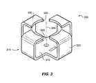
- FIG. 3 describes a keeper 300 according to a preferred embodiment of the invention.
- Keeper 300 is comprised of a substantially flat base portion 305 with a longitudinal axis 350 and four legs 315 extending from flat base portion 305 .
- Each leg 315 is comprised of a lower portion 310 extending from the flat base portion 305, a side portion 320 extending at a right angle from the lower portion 310 and a top portion 330 extending at a right angle from the side portion 320 .
- the top portion 330 has an arcuate interior surface 340 shaped to closely conform to the exterior shape of a magnet (not shown). The magnet sits on the interior surface of flat lower portion 305 with a resulting gap between the magnet exterior and the arcuate surfaces 340 . The gap allows for the passing of a coil (not shown) between the keeper 300 and the magnet.
- Keeper 300 is formed by bending sheet metal to the described shape.
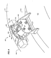
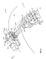
- Magnet portion 410 comprises a magnet mounting bracket 412 for mounting magnet 418 and keeper 300 to conduit 413 .
- Keeper 300 is attached to mounting bracket 412 by screws 416 and washers 417 .
- Magnet assembly 418 is held in place on keeper 412 using a combination of an adhesive, locating features and the magnetic attraction between the magnet assembly 418 and keeper 412 .
- the coil section 460 comprises a coil mounting bracket 462 attached to conduit 411 and a coil 464 attached to the coil mounting bracket 462 by screws 466 and washers 467 .
- the assembled coil 464 resides in a gap between keeper 300 and magnet assembly 418 .
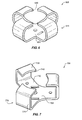
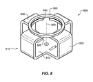
- FIG. 8 describes an another additional alternative keeper 800 .
- Keeper 800 is comprised of a substantially flat base portion 805 with a longitudinal axis 850 and four legs 815 extending from flat base portion 805 .
- Each leg 815 is comprised of a lower portion 810 extending from the flat base portion 805 , a side portion 820 extending at a right angle from the lower portion 810 and a top portion 830 extending at a right angle from the side portion 820 .
- the top portion 830 has an arcuate interior surface 840 shaped to closely conform to the exterior shape of a magnet (not shown).
- a disc member 860 is affixed to top portions 830 of legs 815 .
- disc member 860 allows for complete encirclement of the circumference of the magnetic while keeping the cost of manufacture low.
- the magnet sits on the interior surface of flat lower portion 805 with a resulting gap between the magnet exterior and arcuate surfaces 840 and disc member 860 .
- the gap allows for the passing of a coil (not shown) between the keeper 800 and the magnet (not shown).
Landscapes
- Physics & Mathematics (AREA)
- Fluid Mechanics (AREA)
- General Physics & Mathematics (AREA)
- Measuring Volume Flow (AREA)
- Electromagnets (AREA)
Claims (23)
- Linearaktuator (900), der einen Magnetanker (300) umfasst, wobei der Anker gekennzeichnet ist durch:eine Basis (305); undwenigstens drei sich von der Basis erstreckende Arme (315), wobei jeder Arm. ein unteres Element (310) aufweist, das an der Basis angebracht ist und radial von dieser weg verläuft,ein seitliches Element (320), das an dem unteren Element angebracht ist und von diesem aufwärts verläuft, wobei wenigstens ein Teil des seitlichen Elements parallel zur Längsachse (350) der Basis ist, undein oberes Element (330), das am seitlichen Element angebracht ist und von diesem weg zur Längsachse der Basis hin einwärts verläuft, wobei wenigstens ein Teil des oberen Elements lotrecht zur längsachse der Basis verläuft.
- Linearaktuator nach Anspruch 1, wobei das untere, das seitliche und das obere Element jedes Arms einen kontinuierlichen gekrümmten Steg (615) bilden.
- Linearaktuator nach Anspruch 1, wobei:die unteren Elemente im Wesentlichen lotrecht zur Längsachse der Basis sind;die seitlichen Elemente im Wesentliche parallel zur Längsachse der Basis sind; unddie oberen Elemente im Wesentlichen lotrecht zur Längsachse der Basis sind.
- Linearaktuator nach Anspruch 1, wobei die oberen Elemente jeweils einen bogenförmigen Abschluss (340) haben.
- Linearaktuator nach Anspruch 1, wobei der kombinierte Abschluss jedes oberen Elements wenigstens fünfzig, aber weniger als hundert Prozent des Magnetumfangs umgibt.
- Linearaktuator nach Anspruch 1, wobei das Kenstruktionsmaterial ferromagnetisch ist.
- Linearaktuator nach Anspruch 1 mit vier sich von der Basis erstreckenden Armen.
- Linearaktuator nach Anspruch 1, der ferner ein Scheibenelement (860) umfasst, das an einem oder mehreren der oberen Elemente angebracht ist.
- Herfahren zur Herstellung des Ankers des Linearaktuators nach Anspruch 1, das Folgendes beinhaltet:Bilden eines Materialstücks, das einer Form mit einer Basis und wenigstens drei sich von der Basis erstreckenden Armen entspricht; undBiegen des Materialstücks, so dass jeder Arm Folgendes umfasst:ein unteres Element, das radial von der Basis weg verläuft,ein seitliches Element, das vom unteren Element aufwärts verläuft,wobei wenigstens ein Teil des seitlichen Elements parallel zur Längsachse der Basis ist, undein oberes Element, das vom seitlichen Element einwärts zur Längsachse der Basis hin verläuft, wobei wenigstens ein Teil des oberen Elements lotrecht zur Längsachse der Basis ist.
- Verfahren nach Anspruch 9, wobei der Formschritt Laserstrahlschneide beinhaltet.
- Linearaktuator (400) nach Anspruch 1, wobei der Linearaktuator Folgendes umfasst:eine Magnetbaugruppe (418) mit einem Magnet (518) und dem Arker (300); undeine Spulenbaugruppe (460) mit einer Spule (464), die gleitend mit der Magnetbaugruppe interagiert.
- Linearaktuator nach Anspruch 11, der ferner ein Polstück (530) umfasst.
- Linearaktuator nach Anspruch 11, der ferner eine Magnethülse (527) umfasst.
- Linearaktuator nach Anspruch 11, der ferner einen Montagebügel (412) umfasst.
- Linearaktuator nach Anspruch 14, wobei das Konstruktionsmaterial des Montagebügels ferromagnetisch ist.
- Coriolis-Massendurchflussmesser, der den Linearaktuator nach Anspruch 1 umfasst, wobei der Coriolis-Massendurchflussmesse Folgendes umfaßt:einen Kanal zum Aufnehmen des genannten Materialflusses (411); undwobei der Linearaktuator mit dem Durchflusskanal gekoppelt ist und Folgendes umfasst:eine Magnetbaugruppe mit einem Magnet, undeine Spulenbaugruppe mit einer Spule, die gleitend mit der Magnetbaugruppe interagiert.
- Coriolis-Massendurchflussmesser nach Anspruch 16, wobei das untere, das seitliche und das obere Element jedes Arms einen kontinuierlichen gekrümmten Steg definieren.
- Ceriolis-Massendurchflussmesser nach Anspruch 16, wobei:die unteren Elemente im Wesentlichen lotrecht zur Längsachse der Basis sind;die seitlichen Elemente im Wesentlichen parallel zur Längsachse der Basis sind; unddie oberen Elemente im Wesentlichen lotrecht zur Längsachse der Basis sind.
- Coriolis-Massendurchflussmesser nach Anspruch 16, wobei die oberen Elemente jeweils einen bogenförmigen Abschluss haben.
- Coriolis-Massendurchflussmesser nach Anspruch 16, wobei der kombinierte Abschluss jedes oberen Elements wenigsters fünfzig, aber weniger als hundert Prozent des Magnetumfangs umgibt.
- Coriolis-Massendurchflussmesser nach Anspruch 16, wobei das Konstruktionsmaterial des Ankers ferromagnetisch ist.
- Coriolis-Massendurchflussmesser nach Anspruch 16 mit vier sich von der Basis erstreckenden Armen.
- Coriclis-Massendurchflussmesser nach Anspruch 16, der ferne ein Scheibenelement umfasst, das an einem oder mehreren der oberen Elemente angebracht ist.
Applications Claiming Priority (3)
| Application Number | Priority Date | Filing Date | Title |
|---|---|---|---|
| US205967 | 2002-07-26 | ||
| US10/205,967 US6805012B2 (en) | 2002-07-26 | 2002-07-26 | Linear actuator |
| PCT/US2003/018336 WO2004011888A1 (en) | 2002-07-26 | 2003-06-11 | Linear actuator |
Publications (2)
| Publication Number | Publication Date |
|---|---|
| EP1530706A1 EP1530706A1 (de) | 2005-05-18 |
| EP1530706B1 true EP1530706B1 (de) | 2012-09-05 |
Family
ID=30770187
Family Applications (1)
| Application Number | Title | Priority Date | Filing Date |
|---|---|---|---|
| EP03771540A Expired - Lifetime EP1530706B1 (de) | 2002-07-26 | 2003-06-11 | Linearaktuator |
Country Status (5)
| Country | Link |
|---|---|
| US (1) | US6805012B2 (de) |
| EP (1) | EP1530706B1 (de) |
| JP (2) | JP2005534027A (de) |
| CN (1) | CN100387945C (de) |
| WO (1) | WO2004011888A1 (de) |
Families Citing this family (17)
| Publication number | Priority date | Publication date | Assignee | Title |
|---|---|---|---|---|
| US7160217B2 (en) * | 2005-02-11 | 2007-01-09 | Michael Sohm | Broadhead blade assembly comprising an improved blade design |
| EP1949044B1 (de) * | 2005-10-06 | 2014-05-21 | Micro Motion, Inc. | Magnetbaugruppe |
| FR2907841B1 (fr) * | 2006-10-30 | 2011-04-15 | Snecma | Secteur d'anneau de turbine de turbomachine |
| DE102008007742A1 (de) * | 2007-04-25 | 2008-11-06 | Krohne Ag | Coriolis-Massendurchflußmeßgerät |
| EP2064330A2 (de) | 2007-05-22 | 2009-06-03 | BASF Plant Science GmbH | Pflanzen mit erhöhter toleranz und/oder resistenz gegenüber umweltstress und erhöhter biomasseproduktion |
| BRPI0817005A2 (pt) | 2007-09-18 | 2019-09-24 | Basf Plant Science Gmbh | método para produzir uma célula de planta transgênica, uma planta ou uma parte da mesma com rendimento aumentado, molécula de ácido nucleico, construção de ácido nucleico, vetor, célula hospedeira, processo para produzir um polipeptídeo, polipeptídeo, anticorpo, núcleo de célula de planta transgênica, célula de planta, tecido de planta, material de propagação, material colhido, planta ou parte da mesma, semente, processo para identificar um composto, método para produzir uma composição agrícola, composição, e, uso de uma molécula de ácido nucleico |
| JP4933480B2 (ja) * | 2008-05-09 | 2012-05-16 | 株式会社東海理化電機製作所 | 操作位置検出装置及びシフト装置 |
| AU2009284172A1 (en) | 2008-08-19 | 2010-02-25 | Basf Plant Science Gmbh | Plants with increased yield by increasing or generating one or more activities in a plant or a part thereof |
| DE102008050115A1 (de) | 2008-10-06 | 2010-04-08 | Endress + Hauser Flowtec Ag | In-Line-Meßgerät |
| DE102008050116A1 (de) | 2008-10-06 | 2010-04-08 | Endress + Hauser Flowtec Ag | In-Line-Meßgerät |
| DE102008050113A1 (de) | 2008-10-06 | 2010-04-08 | Endress + Hauser Flowtec Ag | In-Line-Meßgerät |
| DE102008044186A1 (de) * | 2008-11-28 | 2010-06-02 | Endress + Hauser Flowtec Ag | Magneteinrichtung sowie Meßaufnehmer vom Vibrationstyp mit einer solchen Magneteinrichtung |
| US20110114199A1 (en) * | 2009-11-18 | 2011-05-19 | Gosling Thomas M | Actuator mounting assembly |
| DE102009057912B4 (de) * | 2009-12-11 | 2013-07-25 | Krohne Ag | Coriolis-Massendurchflussmessgerät |
| WO2012045852A2 (en) * | 2010-10-08 | 2012-04-12 | 3Win N.V. | Implantable actuator for hearing applications |
| USD701261S1 (en) | 2013-02-12 | 2014-03-18 | Frederick Allen Burton | Camera bracket |
| USD701260S1 (en) | 2013-02-12 | 2014-03-18 | Frederick Allen Burton | Camera bracket |
Family Cites Families (9)
| Publication number | Priority date | Publication date | Assignee | Title |
|---|---|---|---|---|
| US4199123A (en) * | 1978-08-16 | 1980-04-22 | Hughes Aircraft Company | Tripod leveling mechanization |
| JPS56114509U (de) * | 1980-02-04 | 1981-09-03 | ||
| US4988064A (en) * | 1988-05-16 | 1991-01-29 | Hoshino Gakki Co., Ltd. | Tiltable tripod stand |
| US5048350A (en) | 1989-12-05 | 1991-09-17 | The Foxboro Company | Electromagnetic driver and sensor |
| ES2049454T3 (es) | 1990-03-30 | 1994-04-16 | Flowtec Ag | Aparato de medida de caudal de masa que trabaja segun el principio de coriolis. |
| US5003328A (en) * | 1990-05-24 | 1991-03-26 | Gaynor Tyrone L | Photographic tripod apparatus |
| US5987998A (en) * | 1998-08-26 | 1999-11-23 | Micro Motion, Inc. | High temperature drive system for a coriolis mass flowmeter |
| US6189845B1 (en) * | 1999-03-05 | 2001-02-20 | Amy Chen | Tripod |
| US6579017B2 (en) * | 2001-10-31 | 2003-06-17 | David Wei | Tripod |
-
2002
- 2002-07-26 US US10/205,967 patent/US6805012B2/en not_active Expired - Lifetime
-
2003
- 2003-06-11 CN CNB038179784A patent/CN100387945C/zh not_active Expired - Lifetime
- 2003-06-11 JP JP2004524510A patent/JP2005534027A/ja active Pending
- 2003-06-11 WO PCT/US2003/018336 patent/WO2004011888A1/en not_active Ceased
- 2003-06-11 EP EP03771540A patent/EP1530706B1/de not_active Expired - Lifetime
-
2010
- 2010-06-03 JP JP2010127639A patent/JP5128635B2/ja not_active Expired - Fee Related
Also Published As
| Publication number | Publication date |
|---|---|
| JP5128635B2 (ja) | 2013-01-23 |
| US20040016303A1 (en) | 2004-01-29 |
| HK1082543A1 (zh) | 2006-06-09 |
| JP2005534027A (ja) | 2005-11-10 |
| US6805012B2 (en) | 2004-10-19 |
| JP2010281818A (ja) | 2010-12-16 |
| CN100387945C (zh) | 2008-05-14 |
| WO2004011888A1 (en) | 2004-02-05 |
| EP1530706A1 (de) | 2005-05-18 |
| CN1672017A (zh) | 2005-09-21 |
Similar Documents
| Publication | Publication Date | Title |
|---|---|---|
| EP1530706B1 (de) | Linearaktuator | |
| US6883387B2 (en) | Magnetic circuit arrangement for a transducer | |
| EP0210308B1 (de) | Massendurchflussmesser | |
| US4777833A (en) | Ferromagnetic drive and velocity sensors for a coriolis mass flow rate meter | |
| JP3658322B2 (ja) | 振動管路を励振するための駆動源 | |
| US4658657A (en) | Mass flow meter | |
| EP2682721B1 (de) | Magnetanordnung | |
| EP1105700B1 (de) | Hochtemperatur antriebssystem für coriolismassendurchflussmesser | |
| KR102816002B1 (ko) | 진동 유체 계량기를 위한 변환기 | |
| RU2155939C2 (ru) | Расходомер кориолиса и способ измерения расхода с использованием расходомера кориолиса (варианты) | |
| HK1082543B (en) | Linear actuator and method of manufactruing a keeper of linear actuator | |
| CN102032936B (zh) | 磁体装置 | |
| CA1234300A (en) | Mass flowmeter | |
| HK1124915B (en) | Magnet assembly | |
| HK1152106B (en) | Magnet assembly | |
| MXPA00005320A (en) | Driver for oscillating a vibrating conduit |
Legal Events
| Date | Code | Title | Description |
|---|---|---|---|
| PUAI | Public reference made under article 153(3) epc to a published international application that has entered the european phase |
Free format text: ORIGINAL CODE: 0009012 |
|
| 17P | Request for examination filed |
Effective date: 20050106 |
|
| AK | Designated contracting states |
Kind code of ref document: A1 Designated state(s): AT BE BG CH CY CZ DE DK EE ES FI FR GB GR HU IE IT LI LU MC NL PT SE SI SK TR |
|
| RBV | Designated contracting states (corrected) |
Designated state(s): CH DE GB LI |
|
| 17Q | First examination report despatched |
Effective date: 20110518 |
|
| GRAP | Despatch of communication of intention to grant a patent |
Free format text: ORIGINAL CODE: EPIDOSNIGR1 |
|
| GRAS | Grant fee paid |
Free format text: ORIGINAL CODE: EPIDOSNIGR3 |
|
| GRAA | (expected) grant |
Free format text: ORIGINAL CODE: 0009210 |
|
| AK | Designated contracting states |
Kind code of ref document: B1 Designated state(s): CH DE GB LI |
|
| REG | Reference to a national code |
Ref country code: GB Ref legal event code: FG4D |
|
| REG | Reference to a national code |
Ref country code: CH Ref legal event code: EP |
|
| REG | Reference to a national code |
Ref country code: DE Ref legal event code: R096 Ref document number: 60342033 Country of ref document: DE Effective date: 20121031 |
|
| REG | Reference to a national code |
Ref country code: CH Ref legal event code: NV Representative=s name: VOSSIUS AND PARTNER, CH |
|
| PLBE | No opposition filed within time limit |
Free format text: ORIGINAL CODE: 0009261 |
|
| STAA | Information on the status of an ep patent application or granted ep patent |
Free format text: STATUS: NO OPPOSITION FILED WITHIN TIME LIMIT |
|
| 26N | No opposition filed |
Effective date: 20130606 |
|
| REG | Reference to a national code |
Ref country code: DE Ref legal event code: R097 Ref document number: 60342033 Country of ref document: DE Effective date: 20130606 |
|
| REG | Reference to a national code |
Ref country code: CH Ref legal event code: PFA Owner name: MICRO MOTION, INC., US Free format text: FORMER OWNER: MICRO MOTION, INC., US |
|
| PGFP | Annual fee paid to national office [announced via postgrant information from national office to epo] |
Ref country code: GB Payment date: 20220519 Year of fee payment: 20 Ref country code: DE Payment date: 20220518 Year of fee payment: 20 |
|
| PGFP | Annual fee paid to national office [announced via postgrant information from national office to epo] |
Ref country code: CH Payment date: 20220702 Year of fee payment: 20 |
|
| REG | Reference to a national code |
Ref country code: DE Ref legal event code: R071 Ref document number: 60342033 Country of ref document: DE |
|
| REG | Reference to a national code |
Ref country code: CH Ref legal event code: PL |
|
| P01 | Opt-out of the competence of the unified patent court (upc) registered |
Effective date: 20230522 |
|
| REG | Reference to a national code |
Ref country code: GB Ref legal event code: PE20 Expiry date: 20230610 |
|
| PG25 | Lapsed in a contracting state [announced via postgrant information from national office to epo] |
Ref country code: GB Free format text: LAPSE BECAUSE OF EXPIRATION OF PROTECTION Effective date: 20230610 |