EP1529901B1 - Dynamically balanced walk behind trowel - Google Patents
Dynamically balanced walk behind trowel Download PDFInfo
- Publication number
- EP1529901B1 EP1529901B1 EP04025229A EP04025229A EP1529901B1 EP 1529901 B1 EP1529901 B1 EP 1529901B1 EP 04025229 A EP04025229 A EP 04025229A EP 04025229 A EP04025229 A EP 04025229A EP 1529901 B1 EP1529901 B1 EP 1529901B1
- Authority
- EP
- European Patent Office
- Prior art keywords
- trowel
- rotor
- rotational axis
- recited
- guide handle
- Prior art date
- Legal status (The legal status is an assumption and is not a legal conclusion. Google has not performed a legal analysis and makes no representation as to the accuracy of the status listed.)
- Expired - Lifetime
Links
- 230000005484 gravity Effects 0.000 claims abstract description 39
- 238000000034 method Methods 0.000 claims description 21
- 238000006243 chemical reaction Methods 0.000 claims description 5
- 230000000694 effects Effects 0.000 description 6
- 230000008901 benefit Effects 0.000 description 2
- 238000010586 diagram Methods 0.000 description 2
- 239000002828 fuel tank Substances 0.000 description 2
- 229910000831 Steel Inorganic materials 0.000 description 1
- 230000009286 beneficial effect Effects 0.000 description 1
- 230000002301 combined effect Effects 0.000 description 1
- 238000002485 combustion reaction Methods 0.000 description 1
- 238000010276 construction Methods 0.000 description 1
- 230000008878 coupling Effects 0.000 description 1
- 238000010168 coupling process Methods 0.000 description 1
- 238000005859 coupling reaction Methods 0.000 description 1
- 239000003517 fume Substances 0.000 description 1
- 238000009499 grossing Methods 0.000 description 1
- 239000007858 starting material Substances 0.000 description 1
- 230000003068 static effect Effects 0.000 description 1
- 239000010959 steel Substances 0.000 description 1
Images


Classifications
-
- E—FIXED CONSTRUCTIONS
- E04—BUILDING
- E04F—FINISHING WORK ON BUILDINGS, e.g. STAIRS, FLOORS
- E04F21/00—Implements for finishing work on buildings
- E04F21/20—Implements for finishing work on buildings for laying flooring
- E04F21/24—Implements for finishing work on buildings for laying flooring of masses made in situ, e.g. smoothing tools
- E04F21/245—Rotary power trowels, i.e. helicopter trowels
- E04F21/248—Rotary power trowels, i.e. helicopter trowels used by an operator walking behind the trowel, i.e. walk-behind power trowels
Definitions
- the invention relates to concrete finishing trowels and, more particularly, relates to a walk-behind rotary concrete finishing trowel which is dynamically balanced to reduce operator effort.
- the invention additionally relates to a method of operating such a trowel.
- Walk behind trowels are generally known for the finishing of concrete surfaces.
- a walk behind trowel generally includes a rotor formed from a plurality of trowel blades that rest on the ground. The rotor is driven by a motor mounted on a frame or "cage" that overlies the rotor.
- the trowel is controlled by an operator via a handle extending several feet from the cage.
- the rotating trowel blades provide a very effective machine for finishing mid-size and large concrete slabs.
- walk behind trowels have some drawbacks.
- the rotating blades impose substantial forces/torque on the cage that must be counteracted by the operator through the handle.
- blade rotation imposes a torque on the cage and handle that tends to drive the handle to rotate counterclockwise or to the operator's right.
- blade rotation tends to push the entire machine linearly, principally backwards, requiring the operator to push forward on the handle to counteract those forces.
- the combined torque/forces endured by the operator are substantial and tend to increase with the dynamic coefficient of friction encountered by the rotating blades which, in turn, varies with the "wetness" of curing concrete. Counteracting these forces can be extremely fatiguing, particularly considering the fact that the machine is typically operated for several hours at a time.
- US 4,629,359 A discloses a concrete finishing trowel comprising a frame, a motor, an operator controlled guide handle and a rotor with a plurality of blades, whereby the trowel is dynamically balanced such that forces transmitted to the handle upon rotation of the blades in contact with a surface to be finished are substantially reduced when compared to a non-dynamically balanced trowel.
- the object is solved by a trowel according to claim 1 and a method according to claim 17.
- the need additionally has arisen to reduce the operator effort required to steer and control a walk behind rotary trowel.
- a walk behind rotary trowel is configured to be better "dynamically balanced” so as to minimize the forces/torque that the operator must endure to control and guide the trowel.
- the design takes into account both static and dynamic operation and attributes of the trowel, and “balances" these attributes with the operational characteristics of concrete finishing. Characteristics that are accounted for by this design include, but are not limited to, friction, engine torque, machine center of gravity, and guide handle position. As a result, dynamic balancing and consequent force/torque reduction were found to result when the machine's center of gravity was shifted substantially relative to a typical machine's center of gravity.
- This effect can be achieved most practically by reversing the orientation of the engine relative to the guide handle assembly when compared to traditional walk behind rotary trowels and shifting the engine as far as practical to the right. This shifting has been found to reduce the operational forces and torque the operator must endure by at least 50% when compared to traditional machines. Operator fatigue therefore is substantially reduced.
- the Invention further more comprises a concrete finishing trowel comprising:
- An embodiment of said trowel comprises an engine with an output shaft facing to the right of said trowel and a muffler facing forwardly of said trowel.
- a method of builting the concrete finishing trowel comprises the method steps of:
- said trowel comprises the determining method step which includes determining a desired lateral offset.
- the first defined method further more includes the determining step, determining a desired longitudinal offset.
- the first defined method includes in a further embodiment the determining step, comprising determining desired longitudinal and lateral offsets in dependence on one another.
- the first defined method comprises in a further embodiment an offset which is determined taking guide handle length and position, machine center of gravity, and engine torque into account.
- this method comprises an offset which is determined taking finished surface coefficient of friction into account.
- the first defined method comprises in a further embodiment an assembling step, mounting the engine on the frame such that an output shaft of the engine faces to the right of the trowel and a muffler of the engine faces forwardly of the trowel.
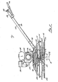
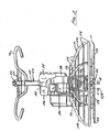
- FIGS. 1-3 A walk behind trowel 10 constructed in accordance with a preferred embodiment of the invention is illustrated in FIGS. 1-3 .
- the walk behind trowel 10 includes a rotor 12, a frame or "cage" 14 that overlies and is supported on the rotor 12, an engine 16 that is supported on the cage 14, a drive train 18 operatively coupling the engine 16 to the rotor 12, and a handle 20 for controlling and steering the trowel 10.
- the rotor 12 includes a plurality of trowel blades 22 extending radially from a hub 24 which, in turn, is driven by a vertical shaft 26.
- the motor 16 comprises an internal combustion engine mounted on the cage 14 above the rotor 12.
- the engine 16 is of the type commonly used on walk behind trowels. It therefore includes a crankcase 30, a fuel tank 32, an air supply system 34, a muffler 36, a pull-chord type starter 38, an output shaft (not shown), etc.
- the drive train 18 may be any structure configured to transfer drive torque from the engine output shaft to the rotor input shaft 26. In the illustrated embodiment, it comprises a centrifugal clutch (not shown) coupled to the motor output shaft and a gearbox 40 that transfers torque from the clutch to the rotor input shaft 26.
- the gearbox is coupled to the clutch by a belt drive assembly 42, shown schematically in FIG. 1 .
- the preferred gearbox 40 is a worm gearbox of the type commonly used on walk behind trowels.
- the handle assembly 12 includes a post 44 and a guide handle 46.
- the post 44 has a lower end 48 attached to the gearbox 40 and an upper end 50 disposed several feet above and behind the lower end 48.
- the guide handle 46 is mounted on the upper end 50 of the post 44.
- a blade pitch adjustment knob 52 is mounted on the upper end 50 of the post 44.
- Other controls, such as throttle control, a kill switch, etc., may be mounted on the post 44 and/or the guide handle 46.
- the cage 14 is formed from a plurality of vertically spaced concentric rings 54 located beneath a deck 56 and interconnected by a number of angled arms 58, each of which extends downwardly from the bottom of the deck 56 to the bottommost rings 54.
- the rings 54 may be made from tubes, barstock, or any other structure that is suitably rigid and strong to support the trowel 10 and protect the rotor 12.
- one or more of the rings 54 may be segmented, with one or more arcuate segment(s) being made of relatively light tubestock, other segment(s) being made of heavier barstock, and/or other segment(s) being eliminated entirely.
- One or more of the arm(s) 58 could be similarly segmented. Weights could also be mounted on the cage 14 at strategic locations to achieve additional strategic weight distribution.
- the trowel's center of gravity "C/G" is offset laterally and longitudinally relative to the rotor's rotation axis "A.” Specifically, the center of gravity is spaced rearwardly and to the right of the rotational axis A.
- the considerations behind this positioning and the optimal positions are discussed in more detail in Section 3 below.
- practical dynamical balancing is best achieved through two effects. First, the engine 16 is rotated 180° relative to the guide handle 20 when compared to a conventional machine. Hence, the fuel tank 32 faces rearwardly, or towards the operator, and the air supply system 34 and muffler 36 face forwardly, away from the operator.
- the torque transfer system 18 is positioned to the operator's right as opposed to his or her left, and the pull chord 38 is positioned on the operator's left as opposed to his or her right.
- the engine 16 therefore can be considered "forward facing" as opposed to "rearward facing.”
- the engine's center of gravity C/G is disposed to the right of trowel's geometric center.
- the gearbox 40 is also rotated 180° to accommodate the engine's reorientation. The combined effect of these reorientations is a significant shift of the machine's center of gravity C/G to the right when compared to prior machines. It also moves the center of gravity C/G to a location further behind the rotor's rotational axis A.
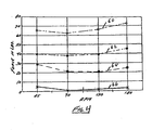
- curves 62 and 66 A comparison of curves 62 and 66 reveals that linear forces, i.e., those resulting from factors other than blade torque and compensated for by offsetting the machine's center of gravity as described above, are reduced from about 178-200 N (40-45 lbs) to less than 44 N (10 lbs) .
- the optimal lateral and longitudinal center of gravity offsets "c" and “d” relative to the rotor's rotational axis A i.e., the optimal center of gravity position for a given trowel design, could be determined purely empirically by trial and error. They could also be determined mathematically by taking practical considerations into account, such as machine geometry and changes in coefficient of dynamic friction experienced by the trowel during the curing concrete process, etc. These calculations will now be explained with reference to FIGS. 5A-5C , which schematically illustrate the forces generated during operation of the walk behind trowel.
- FIG. 5A is a force diagram in the horizontal (XY) plane
- the lines 70 designate the blades, it being assumed that each blade has the same effective length "a,” as measured from the rotor rotational axis A to the centroid of the forces acting on the trowel blade.
- the line 72 designates the handle in the lateral (X) plane and has effective lengths "e" on either side of the center post 44 ( FIGS. 1-3 ), i.e., the guide handle and has a lateral length of 2e.
- the handle 12 has an effective longitudinal length "b," as measured from the rotational axis A of the rotor to the grips on the guide handle as schematically represented by the line 74.
- the four blades are subjected to friction-generated horizontal forces F Af , F Bf , F Cf , and F Df , respectively, which result in corresponding moment arms aF Af , aF Bf , aF Cf , and aF Df about the rotor axis A.
- the handle 12 is subjected to longitudinal (Y) horizontal forces F H2 and F H3 and a lateral (X) force F H1 .
- h height of the guide handle (see line 76 in FIG. 5B ).
- d the longitudinal (Y) offset between the machine's center of gravity C/G and the center of the machine, which coincides with the rotor axis of rotation A.
- d d ⁇ F H ⁇ 1 2 + e ⁇ F H ⁇ 1 ⁇ F H ⁇ 2 - F H ⁇ 3 ⁇ 2 ⁇ F w - F H ⁇ 4 - F H ⁇ 5 + b ⁇ F H ⁇ 4 + F H ⁇ 5 + h ⁇ F H ⁇ 2 + F H ⁇ 3 F w
- a table can then be generated that permits the designer to select the offsets c and d that strike the best balance between F 23 and F 45 .
- the designer may choose to place priority on one of these values, for instance by selecting an offset that reduces F 45 as much as practical while sacrificing some reduction in F 23 .
- the blades 22 are thereupon driven to rotate and contact with the surface to be finished, smoothing the concrete.
- the frictional resistance imposed by the concrete varies, e.g., with the rotor rotation or velocity, the types of blades or pans used to finish the surface and the orientation of the blades or pan relative to the surface, and the coefficient of friction of the surface.
- the operator guides the machine 10 along the surface during this operation using the guide handle. In prior walk behind trowels, this operation would be resisted by substantial forces totaling 267-337 N (60-75 lbs). However, because the trowel 10 is dynamically balanced as described above, the total forces endured by the operator to 89-133 N (20 - 30 lbs), a reduction of well over 50%.
Landscapes
- Engineering & Computer Science (AREA)
- Architecture (AREA)
- Civil Engineering (AREA)
- Structural Engineering (AREA)
- On-Site Construction Work That Accompanies The Preparation And Application Of Concrete (AREA)
- Road Paving Machines (AREA)
- Processing Of Stones Or Stones Resemblance Materials (AREA)
- Motorcycle And Bicycle Frame (AREA)
- Road Repair (AREA)
Applications Claiming Priority (2)
| Application Number | Priority Date | Filing Date | Title |
|---|---|---|---|
| US10/704,105 US6974277B2 (en) | 2003-11-07 | 2003-11-07 | Dynamically balanced walk behind trowel |
| US704105 | 2003-11-07 |
Publications (2)
| Publication Number | Publication Date |
|---|---|
| EP1529901A1 EP1529901A1 (en) | 2005-05-11 |
| EP1529901B1 true EP1529901B1 (en) | 2011-01-19 |
Family
ID=34435587
Family Applications (1)
| Application Number | Title | Priority Date | Filing Date |
|---|---|---|---|
| EP04025229A Expired - Lifetime EP1529901B1 (en) | 2003-11-07 | 2004-10-22 | Dynamically balanced walk behind trowel |
Country Status (10)
| Country | Link |
|---|---|
| US (2) | US6974277B2 (enExample) |
| EP (1) | EP1529901B1 (enExample) |
| JP (1) | JP4774479B2 (enExample) |
| CN (1) | CN100480468C (enExample) |
| AT (1) | ATE496183T1 (enExample) |
| AU (1) | AU2004222802B8 (enExample) |
| BR (1) | BRPI0404793A (enExample) |
| CA (1) | CA2486908C (enExample) |
| DE (1) | DE602004031075D1 (enExample) |
| ES (1) | ES2360050T3 (enExample) |
Families Citing this family (16)
| Publication number | Priority date | Publication date | Assignee | Title |
|---|---|---|---|---|
| US6974277B2 (en) * | 2003-11-07 | 2005-12-13 | Wacker Corporation | Dynamically balanced walk behind trowel |
| US20060204336A1 (en) * | 2005-03-10 | 2006-09-14 | Masterson Randy J | Power trowelling aggregate decorative stone |
| WO2008069901A1 (en) * | 2006-12-04 | 2008-06-12 | Valles Cleto T | Cement heating and finishing machine |
| US7775740B2 (en) * | 2007-07-25 | 2010-08-17 | Wacker Neuson Corporation | Concrete trowel steering system |
| US8132983B2 (en) * | 2008-01-18 | 2012-03-13 | Wacker Neuson Production Americas Llc | Riding concrete trowel with stabilizers |
| DE102010041938A1 (de) * | 2010-10-04 | 2012-04-05 | Robert Bosch Gmbh | Materialverteilungseinheit |
| US10246885B2 (en) | 2014-09-18 | 2019-04-02 | Husqvarna Construction Products North America, Inc. | Grouting pan assembly with reinforcement ring |
| US9580916B2 (en) | 2014-09-18 | 2017-02-28 | Diamond Tool Supply, Inc. | Method for finishing a composite surface and a grounting pan for finishing a composite surface |
| EP3632619B9 (en) | 2015-09-24 | 2021-04-14 | Husqvarna AB | Polishing or grinding pad assembly |
| USD854902S1 (en) | 2016-09-23 | 2019-07-30 | Husqvarna Construction Products North America, Inc. | Polishing or grinding pad |
| USD958626S1 (en) | 2017-08-30 | 2022-07-26 | Husqvarna Ab | Polishing or grinding pad assembly with abrasive disks, reinforcement and pad |
| USD927952S1 (en) | 2017-08-30 | 2021-08-17 | Husqvarna Ab | Polishing or grinding pad assembly with abrasive disk, spacer, reinforcement and pad |
| AU201810919S (en) | 2017-08-30 | 2018-04-13 | Husqvarna Construction Products North America | Polishing or grinding pad assembly with abrasive discs reinforcement and pad |
| US10710214B2 (en) | 2018-01-11 | 2020-07-14 | Husqvarna Ab | Polishing or grinding pad with multilayer reinforcement |
| CN113530167A (zh) * | 2021-06-11 | 2021-10-22 | 烟台南山学院 | 一种手持式自上料抹刀 |
| CN118029649B (zh) * | 2024-04-12 | 2024-06-21 | 石家庄宏业交通建设监理有限公司 | 一种室内墙面抹灰设备 |
Family Cites Families (17)
| Publication number | Priority date | Publication date | Assignee | Title |
|---|---|---|---|---|
| US500647A (en) * | 1893-07-04 | Tobacco stripping and booking machine | ||
| US2842538A (en) * | 1952-10-20 | 1958-07-08 | Saul & Co | Polyazo dyestuffs |
| US2942536A (en) | 1956-11-23 | 1960-06-28 | Master Vibrator Co | Troweling machine |
| JPS5477463A (en) * | 1977-10-28 | 1979-06-20 | Yamazaki Sangyo Kk | Floor polishing machine |
| US4232980A (en) * | 1979-01-08 | 1980-11-11 | Stone Construction Equipment, Inc. | Rotary power trowel |
| US4320986A (en) | 1980-03-21 | 1982-03-23 | Morrison Donald R | Motor powered rotary trowel |
| JPS59136837A (ja) * | 1983-01-27 | 1984-08-06 | Seiko Epson Corp | 記憶型アクテイブパネル内蔵キ−スイツチ |
| US4629359A (en) | 1985-05-31 | 1986-12-16 | Wacker Corporation | Power trowel |
| US5009547A (en) | 1990-01-11 | 1991-04-23 | Clark Jeff A | Water spray for cement finisher |
| US5372452A (en) * | 1993-02-24 | 1994-12-13 | Hodgson; James A. | Power trowels |
| US5890833A (en) * | 1997-01-15 | 1999-04-06 | Allen Engineering Corporation | Hydraulically controlled riding trowel |
| US5993109A (en) * | 1997-07-22 | 1999-11-30 | Wacker Corporation | Power trowel with counterbalanced trowel blade pitch adjust assembly |
| US6368016B1 (en) * | 1999-07-13 | 2002-04-09 | Wacker Corporation | Concrete finishing trowel having an electronically actuated steering assembly |
| US7037150B2 (en) * | 2001-09-28 | 2006-05-02 | Morvillo Robert A | Method and apparatus for controlling a waterjet-driven marine vessel |
| US6907302B2 (en) * | 2001-10-12 | 2005-06-14 | Kar-Tech, Inc. | PDA monitoring and diagnostic system for industrial control |
| US6974277B2 (en) * | 2003-11-07 | 2005-12-13 | Wacker Corporation | Dynamically balanced walk behind trowel |
| JP4240385B2 (ja) * | 2004-02-03 | 2009-03-18 | Necトーキン株式会社 | 表面実装型コンデンサ |
-
2003
- 2003-11-07 US US10/704,105 patent/US6974277B2/en not_active Expired - Lifetime
-
2004
- 2004-10-21 AU AU2004222802A patent/AU2004222802B8/en not_active Ceased
- 2004-10-22 ES ES04025229T patent/ES2360050T3/es not_active Expired - Lifetime
- 2004-10-22 AT AT04025229T patent/ATE496183T1/de not_active IP Right Cessation
- 2004-10-22 EP EP04025229A patent/EP1529901B1/en not_active Expired - Lifetime
- 2004-10-22 DE DE602004031075T patent/DE602004031075D1/de not_active Expired - Lifetime
- 2004-10-29 JP JP2004315689A patent/JP4774479B2/ja not_active Expired - Fee Related
- 2004-11-04 CA CA2486908A patent/CA2486908C/en not_active Expired - Lifetime
- 2004-11-04 BR BR0404793-1A patent/BRPI0404793A/pt not_active Application Discontinuation
- 2004-11-05 CN CNB2004100858841A patent/CN100480468C/zh not_active Expired - Fee Related
-
2005
- 2005-09-16 US US11/228,545 patent/US7172365B2/en not_active Expired - Lifetime
Also Published As
| Publication number | Publication date |
|---|---|
| CA2486908A1 (en) | 2005-05-07 |
| EP1529901A1 (en) | 2005-05-11 |
| AU2004222802B8 (en) | 2009-05-14 |
| US7172365B2 (en) | 2007-02-06 |
| ATE496183T1 (de) | 2011-02-15 |
| US6974277B2 (en) | 2005-12-13 |
| CN100480468C (zh) | 2009-04-22 |
| BRPI0404793A (pt) | 2005-06-28 |
| ES2360050T3 (es) | 2011-05-31 |
| US20060006369A1 (en) | 2006-01-12 |
| US20050100404A1 (en) | 2005-05-12 |
| AU2004222802A1 (en) | 2005-05-26 |
| CA2486908C (en) | 2012-10-30 |
| DE602004031075D1 (de) | 2011-03-03 |
| HK1076300A1 (en) | 2006-01-13 |
| CN1644846A (zh) | 2005-07-27 |
| JP4774479B2 (ja) | 2011-09-14 |
| JP2005139893A (ja) | 2005-06-02 |
| AU2004222802B2 (en) | 2009-05-07 |
Similar Documents
| Publication | Publication Date | Title |
|---|---|---|
| EP1529901B1 (en) | Dynamically balanced walk behind trowel | |
| AU763990B2 (en) | Concrete finishing trowel with improved rotor assembly drive system | |
| US4629359A (en) | Power trowel | |
| EP1561882B1 (en) | Portable vibratory screed with vibration restraint | |
| US5613801A (en) | High performance twin engine rotor-steered riding trowel | |
| US8360680B2 (en) | Hydraulic riding trowels with automatic load sensing | |
| EP2022907B1 (en) | Riding power trowel and method of manually operating the same | |
| EP1069259B1 (en) | Concrete finishing trowel having an electronically actuated steering assembly | |
| JPH09506148A (ja) | 舗装切削鋸 | |
| US20050141962A1 (en) | Metal plate reinforced plastic trowel blade for power troweling | |
| EP0626029B1 (en) | A float finish machine | |
| US20050254896A1 (en) | Rotating concrete finishing trowel | |
| HK1076300B (en) | Dynamically balanced walk behind trowel | |
| US5803658A (en) | Riding trowel with counter rotating rotors | |
| US20110033235A1 (en) | Concrete finishing trowel with speed control | |
| EP1529900A1 (en) | Guide handle for a manually steered machine | |
| US5102258A (en) | Electric powered trowel | |
| US5383330A (en) | Hand-held edger | |
| JPH10248306A (ja) | 管理機 |
Legal Events
| Date | Code | Title | Description |
|---|---|---|---|
| PUAI | Public reference made under article 153(3) epc to a published international application that has entered the european phase |
Free format text: ORIGINAL CODE: 0009012 |
|
| AK | Designated contracting states |
Kind code of ref document: A1 Designated state(s): AT BE BG CH CY CZ DE DK EE ES FI FR GB GR HU IE IT LI LU MC NL PL PT RO SE SI SK TR |
|
| AX | Request for extension of the european patent |
Extension state: AL HR LT LV MK |
|
| 17P | Request for examination filed |
Effective date: 20051026 |
|
| REG | Reference to a national code |
Ref country code: HK Ref legal event code: DE Ref document number: 1076300 Country of ref document: HK |
|
| AKX | Designation fees paid |
Designated state(s): AT BE BG CH CY CZ DE DK EE ES FI FR GB GR HU IE IT LI LU MC NL PL PT RO SE SI SK TR |
|
| 17Q | First examination report despatched |
Effective date: 20061124 |
|
| GRAP | Despatch of communication of intention to grant a patent |
Free format text: ORIGINAL CODE: EPIDOSNIGR1 |
|
| GRAS | Grant fee paid |
Free format text: ORIGINAL CODE: EPIDOSNIGR3 |
|
| GRAA | (expected) grant |
Free format text: ORIGINAL CODE: 0009210 |
|
| AK | Designated contracting states |
Kind code of ref document: B1 Designated state(s): AT BE BG CH CY CZ DE DK EE ES FI FR GB GR HU IE IT LI LU MC NL PL PT RO SE SI SK TR |
|
| REG | Reference to a national code |
Ref country code: GB Ref legal event code: FG4D |
|
| REG | Reference to a national code |
Ref country code: CH Ref legal event code: EP |
|
| REG | Reference to a national code |
Ref country code: IE Ref legal event code: FG4D |
|
| REF | Corresponds to: |
Ref document number: 602004031075 Country of ref document: DE Date of ref document: 20110303 Kind code of ref document: P |
|
| REG | Reference to a national code |
Ref country code: DE Ref legal event code: R096 Ref document number: 602004031075 Country of ref document: DE Effective date: 20110303 |
|
| REG | Reference to a national code |
Ref country code: HK Ref legal event code: GR Ref document number: 1076300 Country of ref document: HK |
|
| REG | Reference to a national code |
Ref country code: SE Ref legal event code: TRGR |
|
| REG | Reference to a national code |
Ref country code: ES Ref legal event code: FG2A Ref document number: 2360050 Country of ref document: ES Kind code of ref document: T3 Effective date: 20110531 |
|
| RAP2 | Party data changed (patent owner data changed or rights of a patent transferred) |
Owner name: WACKER NEUSON CORPORATION |
|
| REG | Reference to a national code |
Ref country code: NL Ref legal event code: VDEP Effective date: 20110119 |
|
| REG | Reference to a national code |
Ref country code: DE Ref legal event code: R082 Ref document number: 602004031075 Country of ref document: DE Representative=s name: MUELLER - HOFFMANN & PARTNER PATENTANWAELTE, DE |
|
| PG25 | Lapsed in a contracting state [announced via postgrant information from national office to epo] |
Ref country code: PT Free format text: LAPSE BECAUSE OF FAILURE TO SUBMIT A TRANSLATION OF THE DESCRIPTION OR TO PAY THE FEE WITHIN THE PRESCRIBED TIME-LIMIT Effective date: 20110519 Ref country code: GR Free format text: LAPSE BECAUSE OF FAILURE TO SUBMIT A TRANSLATION OF THE DESCRIPTION OR TO PAY THE FEE WITHIN THE PRESCRIBED TIME-LIMIT Effective date: 20110420 |
|
| PG25 | Lapsed in a contracting state [announced via postgrant information from national office to epo] |
Ref country code: BE Free format text: LAPSE BECAUSE OF FAILURE TO SUBMIT A TRANSLATION OF THE DESCRIPTION OR TO PAY THE FEE WITHIN THE PRESCRIBED TIME-LIMIT Effective date: 20110119 Ref country code: BG Free format text: LAPSE BECAUSE OF FAILURE TO SUBMIT A TRANSLATION OF THE DESCRIPTION OR TO PAY THE FEE WITHIN THE PRESCRIBED TIME-LIMIT Effective date: 20110419 Ref country code: FI Free format text: LAPSE BECAUSE OF FAILURE TO SUBMIT A TRANSLATION OF THE DESCRIPTION OR TO PAY THE FEE WITHIN THE PRESCRIBED TIME-LIMIT Effective date: 20110119 Ref country code: AT Free format text: LAPSE BECAUSE OF FAILURE TO SUBMIT A TRANSLATION OF THE DESCRIPTION OR TO PAY THE FEE WITHIN THE PRESCRIBED TIME-LIMIT Effective date: 20110119 Ref country code: SI Free format text: LAPSE BECAUSE OF FAILURE TO SUBMIT A TRANSLATION OF THE DESCRIPTION OR TO PAY THE FEE WITHIN THE PRESCRIBED TIME-LIMIT Effective date: 20110119 Ref country code: NL Free format text: LAPSE BECAUSE OF FAILURE TO SUBMIT A TRANSLATION OF THE DESCRIPTION OR TO PAY THE FEE WITHIN THE PRESCRIBED TIME-LIMIT Effective date: 20110119 Ref country code: CY Free format text: LAPSE BECAUSE OF FAILURE TO SUBMIT A TRANSLATION OF THE DESCRIPTION OR TO PAY THE FEE WITHIN THE PRESCRIBED TIME-LIMIT Effective date: 20110119 Ref country code: PL Free format text: LAPSE BECAUSE OF FAILURE TO SUBMIT A TRANSLATION OF THE DESCRIPTION OR TO PAY THE FEE WITHIN THE PRESCRIBED TIME-LIMIT Effective date: 20110119 |
|
| REG | Reference to a national code |
Ref country code: DE Ref legal event code: R081 Ref document number: 602004031075 Country of ref document: DE Owner name: WACKER NEUSON PRODUCTION AMERICAS LLC, MENOMON, US Free format text: FORMER OWNER: WACKER CORP., MENOMONEE FALLS, WIS., US Effective date: 20110722 Ref country code: DE Ref legal event code: R082 Ref document number: 602004031075 Country of ref document: DE Representative=s name: MUELLER HOFFMANN & PARTNER PATENTANWAELTE MBB, DE Effective date: 20110722 |
|
| RAP2 | Party data changed (patent owner data changed or rights of a patent transferred) |
Owner name: WACKER NEUSON PRODUCTION AMERICAS LLC |
|
| PG25 | Lapsed in a contracting state [announced via postgrant information from national office to epo] |
Ref country code: DK Free format text: LAPSE BECAUSE OF FAILURE TO SUBMIT A TRANSLATION OF THE DESCRIPTION OR TO PAY THE FEE WITHIN THE PRESCRIBED TIME-LIMIT Effective date: 20110119 Ref country code: EE Free format text: LAPSE BECAUSE OF FAILURE TO SUBMIT A TRANSLATION OF THE DESCRIPTION OR TO PAY THE FEE WITHIN THE PRESCRIBED TIME-LIMIT Effective date: 20110119 |
|
| PLBE | No opposition filed within time limit |
Free format text: ORIGINAL CODE: 0009261 |
|
| STAA | Information on the status of an ep patent application or granted ep patent |
Free format text: STATUS: NO OPPOSITION FILED WITHIN TIME LIMIT |
|
| PG25 | Lapsed in a contracting state [announced via postgrant information from national office to epo] |
Ref country code: RO Free format text: LAPSE BECAUSE OF FAILURE TO SUBMIT A TRANSLATION OF THE DESCRIPTION OR TO PAY THE FEE WITHIN THE PRESCRIBED TIME-LIMIT Effective date: 20110119 Ref country code: CZ Free format text: LAPSE BECAUSE OF FAILURE TO SUBMIT A TRANSLATION OF THE DESCRIPTION OR TO PAY THE FEE WITHIN THE PRESCRIBED TIME-LIMIT Effective date: 20110119 Ref country code: SK Free format text: LAPSE BECAUSE OF FAILURE TO SUBMIT A TRANSLATION OF THE DESCRIPTION OR TO PAY THE FEE WITHIN THE PRESCRIBED TIME-LIMIT Effective date: 20110119 |
|
| 26N | No opposition filed |
Effective date: 20111020 |
|
| REG | Reference to a national code |
Ref country code: GB Ref legal event code: 732E Free format text: REGISTERED BETWEEN 20111208 AND 20111214 |
|
| REG | Reference to a national code |
Ref country code: DE Ref legal event code: R097 Ref document number: 602004031075 Country of ref document: DE Effective date: 20111020 |
|
| REG | Reference to a national code |
Ref country code: DE Ref legal event code: R082 Ref document number: 602004031075 Country of ref document: DE Representative=s name: MUELLER HOFFMANN & PARTNER PATENTANWAELTE MBB, DE Effective date: 20120112 Ref country code: DE Ref legal event code: R081 Ref document number: 602004031075 Country of ref document: DE Owner name: WACKER NEUSON PRODUCTION AMERICAS LLC, MENOMON, US Free format text: FORMER OWNER: WACKER NEUSON CORP., MENOMONEE FALLS, WIS., US Effective date: 20120112 |
|
| PG25 | Lapsed in a contracting state [announced via postgrant information from national office to epo] |
Ref country code: MC Free format text: LAPSE BECAUSE OF NON-PAYMENT OF DUE FEES Effective date: 20111031 |
|
| REG | Reference to a national code |
Ref country code: CH Ref legal event code: PL |
|
| REG | Reference to a national code |
Ref country code: FR Ref legal event code: ST Effective date: 20120629 |
|
| PG25 | Lapsed in a contracting state [announced via postgrant information from national office to epo] |
Ref country code: CH Free format text: LAPSE BECAUSE OF NON-PAYMENT OF DUE FEES Effective date: 20111031 Ref country code: LI Free format text: LAPSE BECAUSE OF NON-PAYMENT OF DUE FEES Effective date: 20111031 |
|
| REG | Reference to a national code |
Ref country code: IE Ref legal event code: MM4A |
|
| PG25 | Lapsed in a contracting state [announced via postgrant information from national office to epo] |
Ref country code: FR Free format text: LAPSE BECAUSE OF NON-PAYMENT OF DUE FEES Effective date: 20111102 |
|
| REG | Reference to a national code |
Ref country code: AT Ref legal event code: MK05 Ref document number: 496183 Country of ref document: AT Kind code of ref document: T Effective date: 20110119 |
|
| PG25 | Lapsed in a contracting state [announced via postgrant information from national office to epo] |
Ref country code: IE Free format text: LAPSE BECAUSE OF NON-PAYMENT OF DUE FEES Effective date: 20111022 |
|
| PG25 | Lapsed in a contracting state [announced via postgrant information from national office to epo] |
Ref country code: LU Free format text: LAPSE BECAUSE OF NON-PAYMENT OF DUE FEES Effective date: 20111022 |
|
| REG | Reference to a national code |
Ref country code: ES Ref legal event code: FD2A Effective date: 20130605 |
|
| PG25 | Lapsed in a contracting state [announced via postgrant information from national office to epo] |
Ref country code: ES Free format text: LAPSE BECAUSE OF NON-PAYMENT OF DUE FEES Effective date: 20111023 |
|
| PG25 | Lapsed in a contracting state [announced via postgrant information from national office to epo] |
Ref country code: TR Free format text: LAPSE BECAUSE OF FAILURE TO SUBMIT A TRANSLATION OF THE DESCRIPTION OR TO PAY THE FEE WITHIN THE PRESCRIBED TIME-LIMIT Effective date: 20110119 |
|
| PG25 | Lapsed in a contracting state [announced via postgrant information from national office to epo] |
Ref country code: HU Free format text: LAPSE BECAUSE OF FAILURE TO SUBMIT A TRANSLATION OF THE DESCRIPTION OR TO PAY THE FEE WITHIN THE PRESCRIBED TIME-LIMIT Effective date: 20110119 |
|
| PGFP | Annual fee paid to national office [announced via postgrant information from national office to epo] |
Ref country code: IT Payment date: 20151026 Year of fee payment: 12 |
|
| PGFP | Annual fee paid to national office [announced via postgrant information from national office to epo] |
Ref country code: SE Payment date: 20151026 Year of fee payment: 12 |
|
| PG25 | Lapsed in a contracting state [announced via postgrant information from national office to epo] |
Ref country code: SE Free format text: LAPSE BECAUSE OF NON-PAYMENT OF DUE FEES Effective date: 20161023 |
|
| PG25 | Lapsed in a contracting state [announced via postgrant information from national office to epo] |
Ref country code: IT Free format text: LAPSE BECAUSE OF NON-PAYMENT OF DUE FEES Effective date: 20161022 |
|
| REG | Reference to a national code |
Ref country code: DE Ref legal event code: R082 Ref document number: 602004031075 Country of ref document: DE Ref country code: DE Ref legal event code: R081 Ref document number: 602004031075 Country of ref document: DE Owner name: HUSQVARNA AB, SE Free format text: FORMER OWNER: WACKER NEUSON PRODUCTION AMERICAS LLC, MENOMONEE FALLS, WIS., US |
|
| REG | Reference to a national code |
Ref country code: GB Ref legal event code: 732E Free format text: REGISTERED BETWEEN 20200924 AND 20200930 |
|
| REG | Reference to a national code |
Ref country code: GB Ref legal event code: 732E Free format text: REGISTERED BETWEEN 20201001 AND 20201007 |
|
| PGFP | Annual fee paid to national office [announced via postgrant information from national office to epo] |
Ref country code: GB Payment date: 20221012 Year of fee payment: 19 Ref country code: DE Payment date: 20220913 Year of fee payment: 19 |
|
| P01 | Opt-out of the competence of the unified patent court (upc) registered |
Effective date: 20230419 |
|
| REG | Reference to a national code |
Ref country code: DE Ref legal event code: R119 Ref document number: 602004031075 Country of ref document: DE |
|
| GBPC | Gb: european patent ceased through non-payment of renewal fee |
Effective date: 20231022 |
|
| PG25 | Lapsed in a contracting state [announced via postgrant information from national office to epo] |
Ref country code: GB Free format text: LAPSE BECAUSE OF NON-PAYMENT OF DUE FEES Effective date: 20231022 |
|
| PG25 | Lapsed in a contracting state [announced via postgrant information from national office to epo] |
Ref country code: GB Free format text: LAPSE BECAUSE OF NON-PAYMENT OF DUE FEES Effective date: 20231022 Ref country code: DE Free format text: LAPSE BECAUSE OF NON-PAYMENT OF DUE FEES Effective date: 20240501 |