EP1529900A1 - Handgriff für eine handgesteuerte Maschine - Google Patents
Handgriff für eine handgesteuerte Maschine Download PDFInfo
- Publication number
- EP1529900A1 EP1529900A1 EP04025228A EP04025228A EP1529900A1 EP 1529900 A1 EP1529900 A1 EP 1529900A1 EP 04025228 A EP04025228 A EP 04025228A EP 04025228 A EP04025228 A EP 04025228A EP 1529900 A1 EP1529900 A1 EP 1529900A1
- Authority
- EP
- European Patent Office
- Prior art keywords
- guide handle
- post
- handlebars
- recited
- mounting portion
- Prior art date
- Legal status (The legal status is an assumption and is not a legal conclusion. Google has not performed a legal analysis and makes no representation as to the accuracy of the status listed.)
- Withdrawn
Links
- 210000001015 abdomen Anatomy 0.000 claims abstract description 31
- 241000283153 Cetacea Species 0.000 abstract description 10
- 229910000831 Steel Inorganic materials 0.000 description 3
- 238000012986 modification Methods 0.000 description 3
- 230000004048 modification Effects 0.000 description 3
- 239000004033 plastic Substances 0.000 description 3
- 239000010959 steel Substances 0.000 description 3
- 210000002784 stomach Anatomy 0.000 description 3
- 238000006243 chemical reaction Methods 0.000 description 2
- 239000006260 foam Substances 0.000 description 2
- 239000000463 material Substances 0.000 description 2
- 239000005060 rubber Substances 0.000 description 2
- 238000002485 combustion reaction Methods 0.000 description 1
- 230000008878 coupling Effects 0.000 description 1
- 238000010168 coupling process Methods 0.000 description 1
- 238000005859 coupling reaction Methods 0.000 description 1
- 239000002828 fuel tank Substances 0.000 description 1
- 239000002184 metal Substances 0.000 description 1
- 238000000034 method Methods 0.000 description 1
- 230000000284 resting effect Effects 0.000 description 1
Images


Classifications
-
- A—HUMAN NECESSITIES
- A47—FURNITURE; DOMESTIC ARTICLES OR APPLIANCES; COFFEE MILLS; SPICE MILLS; SUCTION CLEANERS IN GENERAL
- A47L—DOMESTIC WASHING OR CLEANING; SUCTION CLEANERS IN GENERAL
- A47L11/00—Machines for cleaning floors, carpets, furniture, walls, or wall coverings
- A47L11/40—Parts or details of machines not provided for in groups A47L11/02 - A47L11/38, or not restricted to one of these groups, e.g. handles, arrangements of switches, skirts, buffers, levers
- A47L11/4075—Handles; levers
-
- B—PERFORMING OPERATIONS; TRANSPORTING
- B25—HAND TOOLS; PORTABLE POWER-DRIVEN TOOLS; MANIPULATORS
- B25F—COMBINATION OR MULTI-PURPOSE TOOLS NOT OTHERWISE PROVIDED FOR; DETAILS OR COMPONENTS OF PORTABLE POWER-DRIVEN TOOLS NOT PARTICULARLY RELATED TO THE OPERATIONS PERFORMED AND NOT OTHERWISE PROVIDED FOR
- B25F5/00—Details or components of portable power-driven tools not particularly related to the operations performed and not otherwise provided for
- B25F5/02—Construction of casings, bodies or handles
-
- E—FIXED CONSTRUCTIONS
- E04—BUILDING
- E04F—FINISHING WORK ON BUILDINGS, e.g. STAIRS, FLOORS
- E04F21/00—Implements for finishing work on buildings
- E04F21/20—Implements for finishing work on buildings for laying flooring
- E04F21/24—Implements for finishing work on buildings for laying flooring of masses made in situ, e.g. smoothing tools
- E04F21/245—Rotary power trowels, i.e. helicopter trowels
- E04F21/248—Rotary power trowels, i.e. helicopter trowels used by an operator walking behind the trowel, i.e. walk-behind power trowels
Definitions
- the invention relates to guide handles and, more particularly, relates to a universal guide handle for a walk behind rotary finishing trowel or other manually guided machine.
- Walk behind trowels are generally known for the finishing of concrete surfaces.
- a walk behind trowel generally includes a rotor formed from a plurality of trowel blades that rest on the ground. The rotor is driven by a motor mounted on a frame or "cage" that overlies the rotor.
- the trowel is controlled by an operator via a handle assembly extending several feet from the cage.
- the handle assembly includes a post and a guide handle.
- the post has a lower end attached to the gearbox and an upper end disposed several feet above and behind the lower end.
- the guide handle is mounted on the upper end of the post.
- a blade pitch adjustment mechanism may be mounted on the upper end of the post or the guide handle.
- Other controls such as throttle control, a kill switch, etc., may be mounted on the post and/or the guide handle. Substantial manual effort is required to control and steer the machine, and the guide handle must therefore be rather robust and provide secure gripping points for the operator.
- Rotary trowels typically have one of two types of guide handles.
- the first is often known as a "bicycle" style handle.
- a bicycle style guide handle comprises a pair of handlebars extending laterally outwardly from the center post in much the same style as a bicycle's handlebars.
- the handlebars typically extend outwardly and upwardly from the center post so that the post and handlebars, in combination, generally take the shape of a Y.
- the handlebars extend horizontally from the post to take the shape of a T. In either event, the terminal ends of the handlebars provide grips for the operator's hands.
- a bicycle style guide handle is disclosed, e.g., in U.S. Patent No. 4,673,311, the contents of which are hereby incorporated by reference in its entirety.
- a bicycle style guide handle has the advantage of providing discrete gripping points for ease of control.
- the free ends of the handlebars also provide convenient locations for hanging buckets or the like.
- the guide handle lacks versatility in gripping options because it provides no surfaces other than the handgrips that can be easily grasped.
- Some bicycle style guide handles also lack a ''belly bar" or center bar against which the operator may rest his or her stomach or chest for pushing the machine and/or resisting rearwardly acting reaction forces generated upon machine operation.
- the second type of guide handle commonly used in walk behind trowels is a so-called "whale tail” style handle.
- a whale tail handle is characterized by first and second opposed enclosed handlebars formed by generally U-shaped handle portions that extend generally horizontal outwardly from the center post. The front, lower leg of each U-shaped portion is connected to the center post. The rear, upper leg of each U-shaped portion is connected to or merges with the corresponding leg of the opposite portion.
- the resultant handle has first and second laterally opposed arcuate gripping portions connected to one another by a belly bar located at the rear of the guide handle. Each handlebar provides a number of different gripping locations that can be grasped by the operator's hands to guide and steer the machine in a manner that best suits that operator's preference.
- a whale tail style guide handle is disclosed, e.g., in U.S. Patent No. 5,993,109, the contents of which are hereby incorporated by reference in their entirety.
- the whale tail handle lacks the free ends that are characteristic of a bicycle style guide handle.
- the bicycle style guide handle and the whale tail style guide handle each have unique characteristics and advantages.
- a guide handle for an industrial machine such as a walk behind trowel.
- the guide handle has handlebars with multiple gripping locations that provide versatile gripping options for the operator and a center belly bar that provides a surface against which an operator may press against with his or her chest or stomach.
- Each handlebar is also provided with an inwardly-facing free end that can serve as a grip or that can be used to hang a bucket or the like.
- the belly bar spans the gap between the two handlebars.
- the handlebars and belly bar are mounted on the center post of the guide handle at the bottom leg of a generally U-shaped portion.
- the mounting portion can be welded or otherwise affixed to a post of a handle assembly at any desired angle, thereby permitting the orientation of the guide handle to be optimized for a given guide handle height.
- a handle assembly having a guide handle as configured above is provided.
- a walk behind trowel having the resultant handle assembly is also provided.
- a guide handle constructed in accordance with the present invention may be used to guide a number of different manually controlled industrial machines. It is particularly well-suited for use with a machine that requires substantial manual effort to guide and control as it moves across a generally horizontal surface. Hence, while a preferred guide handle will now be described in conjunction with a walk behind trowel, it is to be understood that the invention is in no way so limited.
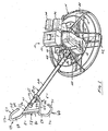
- the walk behind trowel 10 includes a rotor 12, a frame or "cage" 14 that overlies and is supported on the rotor 12, an engine 16 that is supported on the frame 14, a drive train 18 operatively coupling the engine 16 to the rotor 12, and a handle assembly 20 for controlling and steering the trowel 10.
- the rotor 12 includes a plurality of trowel blades 22 extending radially from a hub which, in turn, is driven by a vertical shaft.
- the motor 16 comprises an internal combustion engine mounted on the cage 14 above the rotor 12.
- the engine 16 is of the type commonly used on walk behind trowels. It therefore includes a crankcase 30, a fuel tank 32, an air supply system 34, a muffler 36, an output shaft (not shown), etc.
- the drive train 18 may be any structure configured to transfer drive torque from the engine output shaft to the rotor input shaft. In the illustrated embodiment, it comprises a centrifugal clutch (not shown) coupled to the motor output shaft and a gearbox that transfers torque from the clutch to the rotor input shaft.
- the gearbox is coupled to the clutch by a belt drive assembly 42, shown schematically in FIG. 1.
- the preferred gearbox is a worm gearbox of the type commonly used on walk behind trowels.
- the handle assembly 20 includes a post 44 and a guide handle 46 that extends upwardly and rearwardly from the cage 14.
- the post 44 has a lower end 48 attached to the gearbox and an upper end 50 disposed several feet above and behind the lower end.
- the guide handle 46 is mounted on the upper end 50 of the post 44.
- a blade pitch adjustment knob 52 is mounted on the upper end 50 of the post 44.
- Other controls, such as throttle control, a kill switch, etc., may be mounted on the post 44 and/or the guide handle 46.
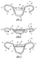
- the guide handle 46 of this embodiment is known as a "rams head” style guide handle to the extent that it generally resembles the head of a ram. It has both an open ended handlebar characteristic of a bicycle style guide handle and a center “belly bar” characteristic and versatility of gripping options of a whale tail style guide handle. It therefore includes a belly bar 58 and opposed open-ended handlebars 60. These structures are integrated in an aesthetically pleasing manner and mounted on the upper end of the post 44 in any convenient manner, preferably using a mounting portion 62 as described below.
- the handlebars 60 and mounting portion 62 are formed integrally with one another as a single subassembly.
- the subassembly is formed from an elongated bent tube.
- the tube of this embodiment is made of bent steel tube stock, but bent steel rod, or any other material that can be formed to the desired shape while providing sufficient rigidity and strength to serve as a control handle, could suffice.
- the tube is bent symmetrically about its center to form the mounting portion 62.
- the mounting portion 62 has first and second generally vertical side legs 64 and 66 connected to one another by a bottom horizontal leg 67.
- the horizontal leg 67 is fixed to the post 44. It is preferably welded to a saddle 69 provided on the rear of the post 44. Because of its connection to the saddle the post is cylindrical the leg 67 can be oriented at any desired angle ⁇ , hence permitting selection of guide handle angle. This ability is advantageous because post length and, accordingly, guide handle height varies with the size of the machine. For instance, the post 44 is considerably longer for a 48" trowel than a 30" trowel, resulting in a higher guide handle position for a 48" trowel than a 30" trowel.
- Operator comfort and steerability can be enhanced by orientating the guide handle 46 at a shallower angle relative to the vertical for a 48" trowel than for a 30" trowel.
- the angle ⁇ for a particular post is preferably pre-selected depending on the length of the post 44 and the resultant handle height.
- other mounting techniques such as clamping, could be used to fix the guide handle 46 to the post at a desired angle.
- Each of the handlebars 60 is formed from a U-shaped bent portion of the rod having upper and lower legs 68 and 70 and a large arcuate center leg 72.
- the upper leg 68 extends outwardly and slightly upwardly from the upper end of the associated leg 64 or 66 of the mounting portion 62 to the upper end of the center leg 72
- the lower leg 70 extends laterally inwardly and slightly downwardly from the bottom end of the center leg 72 to an inwardly facing free end 74.
- a conventional grip (not shown) constructed of rubber, plastic, foam, or the like may be mounted on any or all of the legs 68, 70, and 72, providing high versatility in design and high versatility in gripping options for the operator.
- the free end portion 74 also provides an access point for hanging a bucket or the like.
- the handlebars 60 could be formed from segmented bent tubes such as first and second tubes that are symmetrical about the center of the post 44 and that each have an L-shaped inner portion. In this case, the ends of the "L" meet each other underneath the post 44 to form the aforementioned U-shaped mounting portion 62.
- the belly bar 58 extends at least generally horizontally between the upper ends of the legs 64 and 66 of the U-shaped mounting portion 62. It preferably is generally coplanar with the center legs 72 of the handlebars 60. As with the handlebars 60, the belly bar 58 preferably is formed of steel (preferably flat bar stock), but could be formed from a rigid plastic or any other material meeting the requirements of strength and rigidity. The bar stock is bent to form upper, front, and rear portions 80, 82, and 84, respectively. The opposed ends of each portion are welded to or otherwise affixed to the remainder of the guide handle 46, preferably at the junction between the handlebars 60 and the mounting portion 62. The ends of the belly bar 58 preferably are grooved in an arcuate manner to form receptacles for the associated legs of the combined handlebar/mounting portion.
- the rotor 12 is driven under power of the engine 16 to finish a concrete surface.
- the operator resists reaction forces generated by this operation and also guides and controls the trowel using the guide handle 46.
- the operator may grip the upper leg 68 of each the handlebars 60 in the same manner as a traditional bicycle style guide handle during this operation.
- the operator may grip the arcuate center legs 72 or the lower legs 70. It is even possible or even preferred to grip one leg 68, 70, or 72 of one handlebar 60 with one hand while gripping a different leg of the opposite handlebar 60 with the opposite hand.
- the operator may grip the upper leg 68 of the left handlebar with his or her left hand for comfort while gripping the center leg 72 with his right hand to better resist torque imposed on the guide handle 46 by the rotating rotor 12.
- the operator also has the option of resting his chest or stomach against the belly bar 58 in the same manner as he would using a conventional whale tail style guide handle.
- the handle assembly 120 of this embodiment includes the same post 144, blade pitch adjustment knob 152, and related controls (not shown) as the handle assembly 20 of the first embodiment. It also includes a guide handle 146 that differs from the guide handle 46 of the first embodiment primarily by way of aesthetics and that, therefore, incorporates all of the main characteristics of the guide handle 46 of the first embodiment.
- the guide handle 146 includes a belly bar 158, opposed handlebars 160, and a mounting portion 162.
- the belly bar 158 of this embodiment is formed integrally with the inner ends of the handlebars 160 to form a subassembly. All components of this embodiment are formed from the same type of metal tube or stock.
- Each of the handlebars 160 takes generally the same shape as the corresponding handlebar portion of the first embodiment. It therefore includes an upper leg 168, a lower leg 170, and a center arcuate leg 172.
- the lower leg 170 extends laterally inwardly from the bottom end of the center leg 172 to provide a free end 174.
- a conventional grip (not shown) constructed of rubber, plastic, foam, or the like may be mounted on any or all of the legs 168, 170, and 172.
- the upper leg 168 extends outwardly and upwardly at an angle from an upper end of a link portion 180.
- the belly bar 158 of this embodiment is formed integrally with the handlebars 160, taking the form of a straight portion of the bent tube that extends horizontally between the bottom ends of the opposed link portions 180 of the respective handlebars 160.
- the mounting portion 162 like the mounting portion 62 of the first embodiment, is generally U-shaped, but is formed from a separate piece of tube stock from the combined handlebars/ belly bar. It therefore includes first and second vertical side legs 164 and 166 and a bottom horizontal leg 168.
- the horizontal leg 168 is affixed to the post 144 via a saddle mount 169 as in the first embodiment.
- the upper ends of the vertical side legs 164 and 166 are welded or otherwise affixed to the bottom of the opposed ends of the belly bar 158.
- the guide handle 146 of this embodiment is operated in generally the same manner as the guide handle 46 of the first embodiment. As such, its operation will not be described.
Landscapes
- Engineering & Computer Science (AREA)
- Architecture (AREA)
- Mechanical Engineering (AREA)
- Civil Engineering (AREA)
- Structural Engineering (AREA)
- Steering Devices For Bicycles And Motorcycles (AREA)
- Handcart (AREA)
- Road Paving Machines (AREA)
- Mechanical Control Devices (AREA)
Applications Claiming Priority (2)
| Application Number | Priority Date | Filing Date | Title |
|---|---|---|---|
| US10/703,243 US7065837B2 (en) | 2003-11-07 | 2003-11-07 | Guide handle for a manually steered machine |
| US703243 | 2003-11-07 |
Publications (1)
| Publication Number | Publication Date |
|---|---|
| EP1529900A1 true EP1529900A1 (de) | 2005-05-11 |
Family
ID=34435565
Family Applications (1)
| Application Number | Title | Priority Date | Filing Date |
|---|---|---|---|
| EP04025228A Withdrawn EP1529900A1 (de) | 2003-11-07 | 2004-10-22 | Handgriff für eine handgesteuerte Maschine |
Country Status (7)
| Country | Link |
|---|---|
| US (1) | US7065837B2 (de) |
| EP (1) | EP1529900A1 (de) |
| JP (1) | JP2005141742A (de) |
| CN (1) | CN1637209B (de) |
| AU (1) | AU2004222805A1 (de) |
| BR (1) | BRPI0404782A (de) |
| CA (1) | CA2486961A1 (de) |
Cited By (1)
| Publication number | Priority date | Publication date | Assignee | Title |
|---|---|---|---|---|
| ITMI20130784A1 (it) * | 2013-05-13 | 2014-11-14 | Ghibli S P A | Dispositivo di movimentazione per macchine semoventi |
Families Citing this family (11)
| Publication number | Priority date | Publication date | Assignee | Title |
|---|---|---|---|---|
| JP4500219B2 (ja) * | 2005-06-06 | 2010-07-14 | 三笠産業株式会社 | 振動締固め機の防振ハンドル |
| US20080143067A1 (en) * | 2006-11-30 | 2008-06-19 | John Wicka | Device for controlling wheeled vehicles, wheeled vehicles incorporating such device and methods of operating the same |
| US7775740B2 (en) * | 2007-07-25 | 2010-08-17 | Wacker Neuson Corporation | Concrete trowel steering system |
| USD697098S1 (en) * | 2012-08-17 | 2014-01-07 | Ardisam, Inc. | Auger handle bar |
| USD693860S1 (en) * | 2012-08-17 | 2013-11-19 | Ardisam, Inc. | Auger handle bar |
| US10737138B1 (en) * | 2017-07-18 | 2020-08-11 | Ki-Zen Power Systems, LLC | Handlebars with rebounding punching pads for an exercise device |
| US11759085B2 (en) | 2018-05-29 | 2023-09-19 | Unger Marketing International, Llc | Floor cleaning system |
| USD915703S1 (en) | 2019-05-28 | 2021-04-06 | Unger Marketng International, Llc | Flat headed mop |
| USD923896S1 (en) | 2019-05-28 | 2021-06-29 | Unger Marketing International, Llc | Floor cleaning system |
| US12048404B2 (en) | 2019-12-11 | 2024-07-30 | Unger Marketing International, Llc | Floor cleaning system, flat headed mop and mop pad |
| EP4431244A1 (de) * | 2023-03-17 | 2024-09-18 | MTD Products Inc | Elektrowerkzeug |
Citations (4)
| Publication number | Priority date | Publication date | Assignee | Title |
|---|---|---|---|---|
| GB1181852A (en) * | 1966-06-03 | 1970-02-18 | Hamilton Float And Trowel Ltd | Rotary Surfacing Machines, such as Cement Trowelling Machines |
| US4673311A (en) * | 1985-07-02 | 1987-06-16 | Whiteman Marvin E Jr | Concrete finishing machine having counterbalanced blade pitch adjustment apparatus |
| US5884920A (en) * | 1994-10-25 | 1999-03-23 | Seto; Peter A. | Infant carrier for rough terrain |
| US5993109A (en) * | 1997-07-22 | 1999-11-30 | Wacker Corporation | Power trowel with counterbalanced trowel blade pitch adjust assembly |
Family Cites Families (5)
| Publication number | Priority date | Publication date | Assignee | Title |
|---|---|---|---|---|
| US4198178A (en) * | 1978-06-27 | 1980-04-15 | Dynapac Maskin Ab | Concrete floor finisher |
| US4577993A (en) | 1985-02-22 | 1986-03-25 | Allen Engineering Corporation | Power trowel with cam-actuated blade pitch adjustment mechanism |
| USD323805S (en) * | 1990-06-13 | 1992-02-11 | Profile For Speed, Inc. | Bicycle handlebar |
| USD419123S (en) * | 1998-11-06 | 2000-01-18 | Cat Eye Co., Ltd. | Bicycle speedometer bracket attachment bar |
| USD501633S1 (en) * | 2003-11-07 | 2005-02-08 | Wacker Corporation | Walk behind rotary trowel guide handle |
-
2003
- 2003-11-07 US US10/703,243 patent/US7065837B2/en not_active Expired - Fee Related
-
2004
- 2004-10-21 AU AU2004222805A patent/AU2004222805A1/en not_active Abandoned
- 2004-10-22 EP EP04025228A patent/EP1529900A1/de not_active Withdrawn
- 2004-10-29 JP JP2004315688A patent/JP2005141742A/ja active Pending
- 2004-11-04 BR BR0404782-6A patent/BRPI0404782A/pt not_active Application Discontinuation
- 2004-11-04 CA CA002486961A patent/CA2486961A1/en not_active Abandoned
- 2004-11-05 CN CN2004100858610A patent/CN1637209B/zh not_active Expired - Fee Related
Patent Citations (4)
| Publication number | Priority date | Publication date | Assignee | Title |
|---|---|---|---|---|
| GB1181852A (en) * | 1966-06-03 | 1970-02-18 | Hamilton Float And Trowel Ltd | Rotary Surfacing Machines, such as Cement Trowelling Machines |
| US4673311A (en) * | 1985-07-02 | 1987-06-16 | Whiteman Marvin E Jr | Concrete finishing machine having counterbalanced blade pitch adjustment apparatus |
| US5884920A (en) * | 1994-10-25 | 1999-03-23 | Seto; Peter A. | Infant carrier for rough terrain |
| US5993109A (en) * | 1997-07-22 | 1999-11-30 | Wacker Corporation | Power trowel with counterbalanced trowel blade pitch adjust assembly |
Cited By (2)
| Publication number | Priority date | Publication date | Assignee | Title |
|---|---|---|---|---|
| ITMI20130784A1 (it) * | 2013-05-13 | 2014-11-14 | Ghibli S P A | Dispositivo di movimentazione per macchine semoventi |
| WO2014184648A1 (en) | 2013-05-13 | 2014-11-20 | Ghibli S.P.A. | Steering device for machines for cleaning surfaces |
Also Published As
| Publication number | Publication date |
|---|---|
| US7065837B2 (en) | 2006-06-27 |
| AU2004222805A1 (en) | 2005-05-26 |
| CN1637209A (zh) | 2005-07-13 |
| CN1637209B (zh) | 2011-06-01 |
| BRPI0404782A (pt) | 2005-06-14 |
| JP2005141742A (ja) | 2005-06-02 |
| CA2486961A1 (en) | 2005-05-07 |
| US20050100403A1 (en) | 2005-05-12 |
Similar Documents
| Publication | Publication Date | Title |
|---|---|---|
| US7065837B2 (en) | Guide handle for a manually steered machine | |
| EP0274442B1 (de) | Fahrrad und Lenkstangenvorrichtung | |
| EP0335610B1 (de) | Fahrrad, Lenkstange und Anpassungsvorrichtung | |
| US5145210A (en) | Bicycle, handlebar and adapter system | |
| US4103921A (en) | Rear steering toy wheeled vehicle | |
| US5511810A (en) | Hand driving device for a bicycle | |
| US5082302A (en) | Hand crank bicycle drive | |
| US6595536B1 (en) | Collapsible vehicle | |
| US4333664A (en) | Recumbent vehicle | |
| US4746135A (en) | Pedal crank driven tricycle | |
| US4828427A (en) | Cement screed tool | |
| EP0505643A1 (de) | Mehrzweckübersetzungsgetriebe für ein Fahrrad | |
| US5290054A (en) | Linear drive recumbent cycle | |
| US5201538A (en) | Ergonomic cycles | |
| US7021639B2 (en) | Bicycle of type driven by operation of handle | |
| EP1048558A1 (de) | Lernhilfe für Fahrräder | |
| EP1075785A1 (de) | Kleinkultiviergerät | |
| EP1444128B1 (de) | Pedalvorrichtung | |
| US5713590A (en) | Hand propelled velocipede, quadricycle | |
| EP2479089B1 (de) | Fahrrad mit Sattel für den Sattelständer | |
| JPS6228B2 (de) | ||
| KR101217367B1 (ko) | 킥스쿠터 | |
| US7533894B2 (en) | Cycle direction control system | |
| EP0970881A2 (de) | Fahrrad mit Lenkeranordnung | |
| KR200499785Y1 (ko) | 옷 걸림 방지 자전거 |
Legal Events
| Date | Code | Title | Description |
|---|---|---|---|
| PUAI | Public reference made under article 153(3) epc to a published international application that has entered the european phase |
Free format text: ORIGINAL CODE: 0009012 |
|
| AK | Designated contracting states |
Kind code of ref document: A1 Designated state(s): AT BE BG CH CY CZ DE DK EE ES FI FR GB GR HU IE IT LI LU MC NL PL PT RO SE SI SK TR |
|
| AX | Request for extension of the european patent |
Extension state: AL HR LT LV MK |
|
| AKX | Designation fees paid | ||
| STAA | Information on the status of an ep patent application or granted ep patent |
Free format text: STATUS: THE APPLICATION IS DEEMED TO BE WITHDRAWN |
|
| 18D | Application deemed to be withdrawn |
Effective date: 20051112 |
|
| REG | Reference to a national code |
Ref country code: DE Ref legal event code: 8566 |