EP1529758A1 - Entladungsvorrichtung - Google Patents
Entladungsvorrichtung Download PDFInfo
- Publication number
- EP1529758A1 EP1529758A1 EP03788101A EP03788101A EP1529758A1 EP 1529758 A1 EP1529758 A1 EP 1529758A1 EP 03788101 A EP03788101 A EP 03788101A EP 03788101 A EP03788101 A EP 03788101A EP 1529758 A1 EP1529758 A1 EP 1529758A1
- Authority
- EP
- European Patent Office
- Prior art keywords
- electrode
- discharge device
- shock
- electrodes
- discharge
- Prior art date
- Legal status (The legal status is an assumption and is not a legal conclusion. Google has not performed a legal analysis and makes no representation as to the accuracy of the status listed.)
- Withdrawn
Links
Images






Classifications
-
- C—CHEMISTRY; METALLURGY
- C02—TREATMENT OF WATER, WASTE WATER, SEWAGE, OR SLUDGE
- C02F—TREATMENT OF WATER, WASTE WATER, SEWAGE, OR SLUDGE
- C02F1/00—Treatment of water, waste water, or sewage
- C02F1/46—Treatment of water, waste water, or sewage by electrochemical methods
- C02F1/4608—Treatment of water, waste water, or sewage by electrochemical methods using electrical discharges
-
- H—ELECTRICITY
- H01—ELECTRIC ELEMENTS
- H01T—SPARK GAPS; OVERVOLTAGE ARRESTERS USING SPARK GAPS; SPARKING PLUGS; CORONA DEVICES; GENERATING IONS TO BE INTRODUCED INTO NON-ENCLOSED GASES
- H01T14/00—Spark gaps not provided for in groups H01T2/00 - H01T13/00
-
- C—CHEMISTRY; METALLURGY
- C02—TREATMENT OF WATER, WASTE WATER, SEWAGE, OR SLUDGE
- C02F—TREATMENT OF WATER, WASTE WATER, SEWAGE, OR SLUDGE
- C02F5/00—Softening water; Preventing scale; Adding scale preventatives or scale removers to water, e.g. adding sequestering agents
-
- C—CHEMISTRY; METALLURGY
- C02—TREATMENT OF WATER, WASTE WATER, SEWAGE, OR SLUDGE
- C02F—TREATMENT OF WATER, WASTE WATER, SEWAGE, OR SLUDGE
- C02F5/00—Softening water; Preventing scale; Adding scale preventatives or scale removers to water, e.g. adding sequestering agents
- C02F5/08—Treatment of water with complexing chemicals or other solubilising agents for softening, scale prevention or scale removal, e.g. adding sequestering agents
-
- C—CHEMISTRY; METALLURGY
- C02—TREATMENT OF WATER, WASTE WATER, SEWAGE, OR SLUDGE
- C02F—TREATMENT OF WATER, WASTE WATER, SEWAGE, OR SLUDGE
- C02F1/00—Treatment of water, waste water, or sewage
- C02F1/34—Treatment of water, waste water, or sewage with mechanical oscillations
-
- C—CHEMISTRY; METALLURGY
- C02—TREATMENT OF WATER, WASTE WATER, SEWAGE, OR SLUDGE
- C02F—TREATMENT OF WATER, WASTE WATER, SEWAGE, OR SLUDGE
- C02F1/00—Treatment of water, waste water, or sewage
- C02F1/46—Treatment of water, waste water, or sewage by electrochemical methods
- C02F1/461—Treatment of water, waste water, or sewage by electrochemical methods by electrolysis
- C02F1/46104—Devices therefor; Their operating or servicing
- C02F1/46109—Electrodes
- C02F2001/46123—Movable electrodes
-
- C—CHEMISTRY; METALLURGY
- C02—TREATMENT OF WATER, WASTE WATER, SEWAGE, OR SLUDGE
- C02F—TREATMENT OF WATER, WASTE WATER, SEWAGE, OR SLUDGE
- C02F2201/00—Apparatus for treatment of water, waste water or sewage
- C02F2201/46—Apparatus for electrochemical processes
- C02F2201/461—Electrolysis apparatus
- C02F2201/46105—Details relating to the electrolytic devices
- C02F2201/4612—Controlling or monitoring
Definitions
- the present invention relates to an improvement of a device for generating shock waves by performing discharge.
- shock waves are sometimes generated with the discharge.
- discharge is performed particularly in a liquid under a voltage condition of the dielectric breakdown voltage of the liquid or higher, it is known that enormous shock waves are instantaneously generated with the discharge.
- Use of these shock waves in fragmenting scales in piping or the like in a water treatment apparatus or the like is proposed (JP-A 2000-167591).
- the electrodes come to wastage, and furthermore the electrode clearance is gradually broadened due to the repulsion force by shock waves.
- the clearance between the electrodes exceeds a suitable range, the discharge ceases to be normally performed to remarkably reduce the effect by discharge. Accordingly, it is necessary to frequently adjust the electrode clearance in order to continuously perform stabilized discharge.
- this adjustment is manually performed, the discharge device has to be moved from its installation site, and thus a lot of manpower and time is taken depending on the installation site of the discharge device to increase the time loss of the operation for the adjustment. Then, an automatic clearance adjustment mechanism having a screw feed mechanism is proposed but there has been a problem of durability such as breakage of the thread by repeated shock waves.
- the present invention provides a discharge device having a novel constitution to solve these problems of the conventional discharge devices.
- a first embodiment of the present invention provides a discharge device having a shock-absorbing mechanism which reduces sliding between an electrode and an electrode holding part due to a shock by discharge to reduce the frequency of adjustment of the electrode clearance, and a cross-sectional shape and an arrangement means of constituting parts which reduce an adverse effect on the device due to the shock by discharge.
- a second embodiment of the present invention provides a discharge device having an electrode clearance adjustment mechanism which can automatically adjust the electrode clearance, if required, without moving the discharge device from the installed site thereof, which can easily continue stabilized discharge all the time, and which simultaneously has durability.
- the discharge device is provided with a shock-absorbing mechanism which absorbs or lessens the shock by discharge.
- the first embodiment of the present invention is to solve the above described problems by the following means.
- the discharge device according to the present invention is particularly suited in use as a discharge device to be used in a liquid which performs discharge in the liquid to fragment scales and the like in the liquid passage piping by a shock wave to be generated by discharge.
- a shock-absorbing mechanism can be constituted by arranging a pair of electrodes in series in the vertical direction and rendering the electrode on the upper side movable in the vertical upward direction. According to this mechanism, the electrode on the upper side as such jumps up by the shock caused by discharge to absorb the shock.
- the shock-absorbing mechanism can be constituted by forming a flexed part in the form of a spiral or the like on the electrode as such to absorb the shock by the elastic deformation of the flexed part.
- the shock-absorbing mechanism can be constituted of a shock-absorbing material.
- the shock-absorbing material the one that absorbs the shock by deformation can be utilized and the elastic shock-absorbing material simultaneously having shape restorability is more suitably used. According to this constitution, by the instantaneous deformation of the shock-absorbing material, the shock caused by discharge is absorbed, and thereafter the shock-absorbing material returns to its original shape of itself to restore the electrode clearance to its original distance, and thus discharge can be continually performed.
- the shock-absorbing material can be arranged at least one position between the electrode holding member and the electrode or between the electrode holding member and the discharge vessel. Furthermore, in combination of the above described shock-absorbing mechanism, the cross-sectional shape of the constituting parts and their arrangement which prevent the deterioration of durability of the constituting parts of the discharge device due to the shock can be employed. According to the first embodiment of the present invention, the shock by discharge can be absorbed or lessened by the shock-absorbing mechanism to reduce the deviation of the electrode positions due to sliding between the electrode and the electrode holding member, and accordingly the frequency of adjusting the electrode clearance can be reduced.
- the power charges and the labor of adjusting the electrode clearance can be economized, and furthermore the number of discharging per unit time can be increased to enable more effective discharge treatment. Further, by contriving the cross-sectional shape and the arrangement of constituting parts, the durability of the device even with comparatively inexpensive materials can be improved to economize the device cost and maintenance cost.
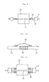
- Fig. 1 is a schematic explanatory diagram showing a mode example of the discharge device relating to the first embodiment of the present invention.
- an upper electrode 1 and a lower electrode 2 are arranged in series in the vertical direction.
- the lower electrode 2 is fixed to the lower support stand 7, and the upper electrode 1 is held by the electrode holding member 3, and the lower side of the holding member 3 is laid on the upper side of the electrode clearance adjustment member 5.
- the upper electrode 1 is held in the state suspended by the electrode holding member 3 in keeping a specified distance from the tip of the lower electrode 2.
- the electrode holding member 3 is not fixed and is movable in the vertical direction alone along the guide pillar 4.
- the upper support stand 6 and the lower support stand 7 are connected by the support pillar 8.
- Fig. 2 shows the state immediately after discharge in the discharge device of Fig. 1.
- the electrode holding member 3 jumps up while holding the upper electrode 1 on getting shocked by discharge to absorb the gotten shock. Thereafter, the electrode holding member 3 falls by gravity and the lower side of the electrode holding member 3 is laid on the upper surface of the electrode clearance adjustment member 5.
- the electrode clearance returns to the original set value and discharge can be continued.
- the position of the upper side of the electrode clearance adjustment member 5 is rendered adjustable by, for example, providing thread chasing on the outer periphery of the guide pillar 4, the electrode clearance becomes adjustable.
- Fig. 3 shows an example in which a projection 9 to be made abut to the electrode clearance adjustment member 5 is provided on the upper electrode 1. According to this embodiment, the electrode holding part 3 can be omitted.
- a flexed part 10 which functions as a shock-absorbing part is formed on the upper electrode 1 as such is shown. According to this mode, since the shock by discharge is absorbed at the flexed part 10 of the upper electrode 1, the sliding between the electrode holding member 3 and the electrode 1 is reduced.
- the present invention also includes an embodiment in which a spiral shock- absorbing part is formed on the above described electrode 1 as shown in Fig. 5.
- this spiral shock-absorbing part is horizontally shown because of limited space of paper.
- Fig. 6 shows another mode example of the discharge device relating to the first embodiment of the present invention.
- an electrode holding member 3 by holding the part of the electrode 11 protruded outwardly of the discharge vessel 13 by an electrode holding member 3 and constituting the holding part 12 of the electrode holding member 3 of an elastic material having shape restorability such as a rubber, a rubber tube and a sponge, holding of the electrode and absorption of the shock caused on the electrode by discharge are simultaneously effected.
- the rubber a foamed rubber and a silicone rubber which have both some hardness and elasticity are preferably used, and a rubber made hollow such a rubber tube is more preferably used.
- the sponge and gel as well, those having hardness to some extent are preferred from the standpoint of holding.
- Fig. 7 shows the state immediately after discharge in the discharge device as shown in Fig. 6.
- the shock caused on the electrode 11 by discharge is absorbed by the deformation of the holding part 12 of the holding member 3.
- the holding member 3 returns to the state as shown in Fig. 6 by the shape restorability of the holding part 12, and accordingly the electrode clearance also returns to its original state to enable discharge again.
- the sliding between the electrode holding member 3 and the electrode 11 due to the shock is reduced by the deformation of the holding part 12 to absorb the shock, and thus the electrode holding member 3 may be fixed to the discharge vessel 13.
- Fig. 8 shows another mode example of the discharge device relating to the first embodiment of the present invention.
- an electrode 11 and the opposed pairing electrode 17 are connected in the discharge vessel 13 by a shock-absorbing member 14 composed of an elastic material having insulation properties and shape restorability to absorb the shock acting on both electrodes by the deformation of the shock-absorbing member 14.
- the electrode clearance between the electrode 11 and the pairing electrode 17 returns again to the original distance by the shape restorability of the shock-absorbing member 14, and thus discharge can be continued.
- the electrode holding member 3 is not fixed to the discharge vessel 13 and is placed on a pedestal 16 having a sliding surface 15 in the mode as shown in Fig. 8.
- a spring As the elastic material constituting the shock-absorbing member 14, a spring, a rubber, an air pressure suspension, a water pressure suspension, a hydraulic (water or oil pressure) suspension, a gel, a plastic and the like can be utilized.
- a coil spring made of a plastic is preferred.
- the rubber and gel the ones that have hardness to some extent are preferred, and a hard rubber, a silicone gel and the like are more preferred. Since the electrode holding member 3 and the electrode 11can integrally move on the sliding surface 15, the sliding between the electrode holding members and the electrodes due to the shock is reduced.
- a lubrication mechanism such as a roller, a bearing and a lubricating oil or a mechanism which reduces frictional resistance such as air floatation and magnetic floatation can be utilized.
- a structure of holding the electrode as such through the lubrication mechanism or the frictional resistance-reducing mechanism does not require the electrode holding member 3.
- Fig. 9 shows another mode example of the discharge device relating to the first embodiment of the present invention.
- the discharge device as shown in Fig.9 has electrode holding members 3, a discharge vessel 13, shock-absorbing materials 14, electrode support parts 18 and electrode tips 19.
- the same shock-absorbing member 14 as shown in Fig. 8 is arranged between the electrode support part 18 and the electrode tip 19 to hold the electrode support part 18 and the electrode tip 19 in a separated manner.
- the shock caused on the electrode tips 19 by discharge is absorbed by the shock-absorbing members 14.
- a spring or the like can be used as the shock-absorbing member 14, and it is preferred that the shock-absorbing member 14 as such has electrical conductivity, and thus the one made of a metal is preferred, and it is preferred that the shape is of a coil spring.
- the rubber and gel those having hardness to some extent are preferred and a hard rubber and a silicone gel are preferred.
- the shock-absorbing member 14 is an insulating material or the electrical conductivity of the shock-absorbing member 14 is insufficient, it is possible to connect a conductor from an electric power source directly to the electrode tip 19 or, as shown in Fig. 10, to arrange a conductor 20 between the electrode tip 19 and the electrode support part 18 to electrically connect the separated electrode tip 19 and the electrode support part 18.
- Fig. 11 shows another mode example of the discharge device relating to the first embodiment of the present invention.
- the electrodes 11 are held by the electrode holding members 3, and a shock-absorbing members 14 are installed between the electrode holding members 3 and the discharge vessel 13.
- the shock caused on the electrode 11 by discharge is absorbed by the shock-absorbing members 14 through the electrode holding members 3.
- the above described shock-absorbing mechanism is provided, and furthermore at least part of the cross-sectional shape of constituting parts of the discharge device can be rendered an approximately polygonal shape having an approximately streamlined or acute angular part which is hard to be susceptible to the affect of a shock.
- Fig. 12 shows examples of cross-sectional shapes of constituting parts which are less susceptible to the affect of a shock.
- the approximately streamlined shapes include, for example, shapes having a curved line such as a circle, an ellipse and a bullet-shape, and shapes having an acute angle include, for example, a triangle, a parallelogram, a pentagon and a hexagon.
- the constituting parts having such cross-sectional shapes are installed in the discharge device, it is preferred to install them so as to direct the narrowed portion in the case of the approximated streamlined shape of the cross-section, and to direct the acute portion in the case of the approximately polygonal shapes, to respective discharge points.
- Fig. 13 shows an example in which pillar 8 is constituted by a member having an elliptical cross-section shape and the upper support stand 6 and the lower support stand 7 are constituted by a member having a pentagonal cross-sectional shape.
- the direction of the longer diameter of the elliptical pillars and the acute angular part of the pentagon are preferably arranged directed to discharge points.
- the present invention has another object to provide a discharge device having an electrode clearance adjustment mechanism which can automatically control the electrode clearance, if required, without moving the discharge device from its installation site and which is capable of easily continuing stabilized discharge all the time and simultaneously having durability.
- the second embodiment of the present invention provides a discharge device having a pair of electrodes and an electrode clearance adjustment mechanism which is constituted by attaching to at least one of the above described electrodes, an electrode holder to hold and release the electrode, a driving mechanism which moves the electrode holder, a stopper to control the movement position of the electrode holder, the electrode clearance adjustment mechanism controlling the distance of the electrode from the other electrode by moving the electrode held by the electrode holder to the position regulated by the stopper.
- the spacing distance between electrodes by this mechanism, by previously making the tips of both electrodes abut to each other by a means to make both electrodes abut to each other and moving the electrode held by the electrode holder in the contact state to a position regulated by the stopper, the spacing distance can be precisely adjusted.
- the electrode clearance adjustment mechanism can be constituted of a plurality of sets of an electrode holder and a driving mechanism which allows the plurality of electrode holders to hold and release the electrode at a plurality of positions to move and let out the position of the electrode.
- the second embodiment of the present invention also provides a discharge device having a pair of electrodes arranged in series in the upward and downward directions and an electrode clearance adjustment mechanisms which is constituted of an electrode holder to hold and release the electrode installed on the upper side and a driving mechanism to allow the electrode holder to ascend in the upward direction to a predetermined distance, and which functions to separate the electrode on the upper side from the electrode on the lower side to the predetermined distance by releasing the electrode holder to allow the electrode on the upper side to descend by gravity to make it abut to the other electrode installed on the lower side, and subsequently holding the electrode on the upper side by the electrode holder to allow the electrode holder to ascend to the predetermined distance.
- utilization of gravity as the means to make both electrodes abut to each other can reduce the power to be used and makes control as well easy.
- the driving mechanism which moves the electrode holder can be constituted of a mechanism driven by a liquid pressure or a gas pressure.
- the durability against electrical noise to be generated by discharge or the like can be improved to reduce malfunctioning.
- the liquid pressure an oil and water are typically used as the pressure medium and may be properly used depending on the use environment.
- water pressure is preferred, and an anti-freeze may be added to an aqueous medium of water pressure when the device is used at low temperatures.
- the gas pressure air, an inert gas and the like which are non-explosive and nonflammable gases are preferably used.
- the second embodiment of the present invention also provides a discharge device having a pair of electrodes and an electrode clearance adjustment mechanism which is constituted by attaching to at least one of the above described electrodes, a roller conveyor to hold and feed the electrode and a driving mechanism which drives the roller conveyor, and which functions to adjust the spacing distance of the electrode from the other electrode by moving the electrode held by the roller conveyor.
- a roller conveyor to be used in this case, the one that holds the electrode between one or more sets of roller conveyors, that can freely let out the electrode by a driving source, and that can hold the electrode so as not to carelessly move it when the roller conveyors are stopped, may be used.
- the electrode is held from two or more directions, and in order to improve holding stability, holding from three or more directions is preferred.
- Each concrete mode of the second embodiment of the present invention is as follows. 14.
- a discharge device having a pair of electrodes and an electrode clearance adjustment mechanism which is constituted by attaching to at least one of said electrodes, an electrode holder to hold and release the electrode, a driving mechanism to move the electrode holder and a stopper to regulate the movement position of the electrode holder, and which functions to adjust the spacing distance from the other electrode by moving the electrode held by the electrode holder to the position regulated by the stopper.
- 15. The discharge device of the above described item 14, wherein a plurality of sets of an electrode holder and a driving mechanism to move the electrode holders are arranged and the electrode clearance adjustment mechanism allows the plurality of electrode holders to hold and release the electrodes at a plurality of positions to move the electrodes. 16.
- a discharge device having a pair of electrodes installed in series in the upward and downward directions and an electrode clearance adjustment mechanism which is constituted of an electrode holder to hold and release the electrode installed on the upper side and a driving mechanism to allow the electrode holder to ascend in the upward direction to a predetermined distance, and which functions to separate the electrode on the upper side from the other electrode on the lower side to the predetermined distance by releasing the electrode holder to allow the electrode on the upper side to descend by gravity to make it abut to the other electrode installed on the lower side, and then holding the electrode on the upper side by the electrode holder to allow the electrode holder to ascend to a predetermined distance. 17.
- a discharge device having a pair of electrodes and an electrode clearance adjustment mechanism which is constituted by attaching to at least one of the above described electrodes, a roller conveyor to hold and feed the electrode and a driving mechanism to drive the roller conveyor, which functions to adjust the spacing distance from the other electrode by moving the electrode held by the roller conveyor. 18.
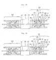
- Fig. 14 is a schematic cross-sectional diagram (schematic view) showing one mode example of the discharge device relating to the second embodiment of the present invention.
- the discharge device has a pair of bar electrodes 31 and 31' whose tips are separately opposed with a predetermined clearance (an optimum clearance for discharge), a discharge vessel 33 for housing the opposed tips of the above described electrodes 31 and 31' and electrode clearance adjustment mechanisms 50 and 50' which are installed on both sides of the discharge vessel 33 and hold and move the portions of both electrodes 31 and 31' protruded outwardly of the discharge vessel 33.
- a discharge device in a liquid is constituted by filling the discharge vessel 33 with the liquid, which performs discharge in the liquid to fragment scales and the like in liquid passage piping by shock waves to be generated by discharge.
- the embodiment using a discharge device in a liquid obtained by filling the discharge vessel 33 with a liquid will be explained.
- each of the electrode clearance adjustment mechanisms 50 and 50' is symmetrical in the shape and structure.
- the electrode clearance adjustment mechanism 50 on the right will be explained.
- “front” means the side of the discharge vessel 33 viewed from a cylinder 37 as will be explained below and “rear” means the side of a pusher 41 viewed from the cylinder 37.
- stoppers 36-1 and 36-2 are fixed to two front and rear positions on the opposed surfaces of the upper and lower stands 43, respectively, and the cylinder 37 is housed between two stoppers 36-1 and 36-2 and a toroidal electrode holder 35 is fixed and integrated on the inner side of the cylinder 37, and furthermore, a pusher 41 is installed at the rear side of the rear stopper 36-2.
- the cylinder 37 is installed movably in the forward and backward directions between the stopper 36-1 and 36-2.
- the cylinder 37 is constituted to eject a shaft 38 in any one of the front and rear directions, to thereby be driven in the opposite direction of ejection of the shaft 38.
- Fig.14 shows the state of the cylinder 38 which ejects the shaft 38 in the front direction to thereby be moved to the position to abut to the rear stopper 36-2.
- the electrode holder 35 fixed on the inner side of the cylinder 37 is moved in the front or rear direction in accordance with this movement of the cylinder 37 in the front or rear direction.
- a liquid pressure such as a hydraulic pressure and an oil pressure, a gas pressure and, in addition, an electromagnetic force and the like may be used.
- the cylinder 37 is constituted to eject the shaft 38 in any one of the front and rear directions to thereby be moved to the position to abut to either of the stoppers 36-1 and 36-2 and to take either one of these two positions (two-position control). With this movement of the cylinder 37 in the front or rear direction, the electrode holders 35 is also moved forward or backward to the position to abut to the stopper 36-1 or 36-2 together with the cylinder 37 and takes either one of these two positions.
- the electrode holder 35 is constituted of a hollow toroidal rubber holder and holds the periphery of the above described electrode 31 by injecting a fluid such as a liquid and a gas into its inside of the electrode holder.
- the driving source for the electrode holder 35 may be constituted of the one using a liquid pressure such as a hydraulic pressure and an oil pressure, a gas pressure and, in addition, and an electromagnetic force or the like.
- the pusher 41 has a pressing part 42 at the position opposed to the rear end surface of the electrode 31 and is moved forward by ejecting the pressing part 42 forward to press the rear end of the electrode 31 and to move the electrode 31 forward.
- a liquid pressure such as a hydraulic pressure and an oil pressure, a gas pressure and, in addition, an electromagnetic force and the like can also be used.
- Fig. 14 shows the state of the discharge device on the normal discharge.
- Fig. 15 to Fig. 17 are explanatory diagrams of a method of adjusting the electrode clearance of the discharge device by using the electrode clearance adjustment mechanism 50.
- Fig. 18 shows the state of each part (an electrode holder 35, a cylinder 37 and a pusher 4) in each state of action of the electrode clearance adjustment mechanism 50.
- the Figure number as shown in the last line of Fig. 18 (table) shows the number of the figure (Fig. 14 to Fig. 17) which shows each state.
- Fig. 14 shows the state of the discharge device on the normal discharge.
- Fig. 15 to Fig. 17 are explanatory diagrams of a method of adjusting the electrode clearance of the discharge device by using the electrode clearance adjustment mechanism 50.
- Fig. 18 shows the state of each part (an electrode holder 35, a cylinder 37 and a pusher 4) in each state of action of the electrode clearance adjustment mechanism 50.
- the electrode holder 35 When the discharge device relating to the present invention is in the state of the normal discharge as shown in Fig. 14, the electrode holder 35 is rendered “ON" to hold the electrode 31 as shown in "State 1-1" in Fig. 18; that is, the shaft 38 is ejected toward the discharge vessel 33 so that the cylinder 37 is moved backward.
- a voltage of the dielectric breakdown voltage of the liquid in the discharge vessel or higher is applied between the electrodes 31 and 31' in this state to effect discharge, enormous shock waves and the like are generated to fragment and remove scales, rust and the like adhering to the inside of the discharge vessel 33 or to prevent adhesion of scales, rust and the like to the inside of the discharge vessel 33.
- the clearance between the tips of the electrodes 31 and 31' is gradually broadened not only by the wastage (or consumption) of electrodes but also the sliding of electrode caused by the repulsion force due to the shock waves.
- the clearance between the tips of the electrodes 31 and 31' exceeds an appropriate range and normal discharge ceases to be performed to remarkably deteriorate the effect of discharge, the discharge is stopped and the clearance between the electrodes 31 and 31' are appropriately adjusted using the electrode clearance adjustment mechanism 50 according to the present invention.
- the pusher 41 is rendered “OFF” and allowed to retreat, and simultaneously the cylinder 37 is rendered “OFF” and the shaft 38 is ejected in the direction to the stopper 36-2 (that is, in the rear direction) to move the cylinder 37 forward (in the direction to the discharge vessel 33) ("State 1-4" in Fig.18).
- the electrode holder 35 is rendered “ON” to hold the electrode 31.
- the cylinder 37 is rendered “ON” and the shaft 38 is ejected in the (front) direction of the stopper 36-1 to move the cylinder 37 backward and the electrode holder 35 is returned to the original position as shown in Fig.
- the clearance between the electrodes 31 an 31' is appropriately adjusted.
- the clearance between the electrodes 31 and 31' after adjustment is preset as the distance of movement of the cylinder 37 between the stoppers 36-1 and 36-2, and accordingly the preset value of the electrode clearance can be adjusted in accordance with the positions of the stoppers 36-1 and 36-2.
- the pusher 41, the electrode holder 35, the cylinder (driving mechanism) 37 and the stoppers 36-1 and 36-2 constitute the electrode feeding mechanism capable of controlling the electrode positions.
- the electrode clearance adjustment mechanism 50 may function when it is installed on at least any one of the electrodes 31 and 31', but as in the mode as shown in Fig. 14 to Fig. 17, the electrode clearance adjustment mechanisms may be installed on both electrodes 31 and 31' and may be alternately operated. Further, in this mode, the electrode holder 35 is held by the upper and lower cylinders 37 but the cylinders 37 may be one, and further three or more cylinders may be installed on the periphery of the electrode holder 35.
- Fig. 19 is a schematic cross-sectional diagram (schematic view) showing another mode of the discharge device relating to the second embodiment of the present invention.
- the same numerals are affixed to the same or corresponding constituting elements as in the mode as shown in Fig. 14 and their detailed explanation is omitted.
- the point which differs from the mode as shown in the above described Fig. 14 is that a stopper 36-3 on the rear side of the stopper 36-2 instead of the pusher 41, a second cylinder 37-2 between the stoppers 36-2 and 36-3, and a second electrode holder 35-2 on the inner side of the second cylinder 37-2, are further installed.
- the elements corresponding to the cylinder 37 and the electrode holder 35 in Fig. 14 are called as a first cylinder 37-1 and a first electrode holder 35-1 in Fig. 19, respectively.
- two sets of cylinders 37-1 and 37-2 and electrode holders 35-1 and 35-2 which have the same structures are installed to constitute an electrode feeding mechanism.
- Fig. 19 shows the normal discharge state of the discharge device relating to the present invention.
- Fig. 20 to Fig. 24 are explanatory diagrams of a method of adjusting the electrode clearance of the discharge device with the use of one side of the electrode clearance adjustment mechanisms 50.
- Fig. 25 is a table showing the state of each part (a first electrode holder 35-1, a second electrode holder 35-2, a first cylinder 37-1 and a second cylinder 37-2) in each state of action of the electrode clearance adjustment mechanism 50.
- the Figure number as shown in the last line in Fig. 25 shows the number of the Figure (Fig. 19 to Fig. 24) which shows each state.
- "ON" and "OFF" of the first electrode holder 35-1, the second electrode holder 35-2, the first cylinder 37-1 and the second cylinder 37-2 shows the same meaning as explained with respect to Fig. 18.
- the discharge device relating to the present invention When the discharge device relating to the present invention is in the normal discharge state as shown in Fig. 19, as shown in "State 2-1" in Fig. 25, the first electrode holder 35-1, the second electrode holder 35-2, the first cylinder 37-1 and the second cylinder 37-2 are all "ON" and the first electrode holder 35-1 abuts to the rear stopper 36-2 and holds the electrode 31, and the second electrode holder 35-2 abuts to the rear stopper 36-3 and holds the electrode 31.
- the second cylinder 37-2 is rendered “OFF” to move the second electrode holder 35-2 forward while holding the electrode 31, and the electrode 31 is pushed forward (in other words, toward the opposed electrode 31') ("State 2-3" in Fig. 25).
- the electrode 31 is moved forward until the second cylinder 37-2 abuts to the front stopper 36-2.
- the electrode holder 35-1 is rendered “ON” to hold the electrode 31 ("State 2-4" in Fig. 25), and then as shown in Fig. 22, the second electrode holder 35-2 is rendered “OFF” to release the electrode 31 ("State 2-5").
- the first cylinder is rendered “OFF” to move the cylinder 37-1 forward, and the electrode 31 is pushed forward while holding the electrode 31 by the electrode holder 35-1, whereby the tip of the electrode 31 abuts to the tip of the opposed electrode 31' and the cylinder 37-1 is stopped in the middle of pushing the electrode 31 ("State 2-6").
- the second electrode holder 35-2 is rendered “ON” to hold the electrode 31 ("State 2-7") and the first electrode holder 35-1 is rendered “OFF” to release the electrode 31 ("State 2-8").
- the second cylinder 37-2 is rendered "ON” and is moved backward, whereby the electrode 31 is moved backward with the second electrode holder 35-2 and the tips of both electrodes 31 and 31' are drawn apart ("State 2-9). Since the clearance between the electrodes 31 and 31' is preset as the distance which the second cylinder 37-2 (in other words, the second electrode holder 35-2) between the stoppers 36-2 and 36-3 can move, the preset value of the clearance between the electrodes can be adjusted in accordance with the positions of the stoppers 36-2 and 36-3.
- the first cylinder 37-1 is rendered “ON” to move it in the direction to the stopper 36-2 (in other words, backward) ("State 2-10) and the first electrode holder 35-1 is rendered “ON” to hold the electrode 31, whereby the state capable of performing the normal discharge as shown in the above described Fig. 19 can return.
- Fig. 26 is a schematic cross-sectional diagram (schematic view) showing another mode example of the discharge device relating to the second embodiment of the present invention.
- the same numerals are affixed to the same or corresponding constituting elements as in the mode as shown in Fig. 14 and their detailed explanation is omitted.
- a discharge vessel 33 which houses the opposed tips of the above described electrodes 31 and 31' and is filled with a liquid and electrode clearance adjustment mechanisms 50 and 50' which are installed on both sides of the discharge vessel 33 and hold and move the parts of both electrodes 31 and 31' protruded outwardly of the discharge vessel 33 in the same manner as in the discharge device of Fig. 14.
- the electrode clearance adjustment mechanisms 50 is constituted by installing a pair of roller conveyors 46-1 and 46-2 which holds an electrode 31 from its upper and lower directions and a pair of roller conveyors 46-3 and 46-4 (not shown since the roller conveyor46-4 is installed in the inner side) which holds the electrode 31 in its right and left directions between support stands 43.
- the mechanism 50 accordingly securely holds the electrode 31 at two positions in the directions crossing at right angles.
- At least one of the conveyor rollers 46-1, 46-2, 46-3 and 46-4 is connected to a driving mechanism, and when the rotation and stopping of the roller conveyers are controlled by driving this driving mechanism, the clearance between both electrodes 31 and 31'can be adjusted to any distance by moving the electrode 31 forward or backward. Further, microadjustment control is also possible. In other words, by two sets of the roller conveyers 46-1, 46-2 and 46-3 and 46-4, holding of the electrode 31 and the clearance adjustment between the electrodes 31 and 31' can be simultaneously performed.
- Fig. 27 is a schematic cross-sectional diagram (schematic view) showing another mode example of the discharge device relating to the second embodiment of the present invention.
- the same numerals are affixed to the same or corresponding constituting elements as in the mode as shown in Fig. 14 and their detailed explanation is omitted.
- the discharge device of the mode as shown in Fig. 27 inside between upper and lower support stands 61 and 61' is used as a discharge vessel 33 which is filled with a liquid, and an electrode 62 (the lower fixed electrode) is rendered protruded from the lower support stand 61 in the vertical upward direction.
- both electrodes 62 and 63 are arranged in such a manner that their tips are separately opposed with a predetermined clearance (an optimum distance for discharge).
- This discharge device is usable when both electrode 62 and 63 are installed in the upward and downward directions (preferably in the vertical direction) and is of the type of adjusting the electrode 63 on the upper side alone and fixing the electrode 62 on the lower side.
- an electrode clearance adjustment mechanism 50 is constituted by a set of the cylinder 37 and the electrode holder 35 which holds and moves the part of the electrode protruded outwardly of the upper side of the discharge vessel 33.
- a cylinder of taking two positions by protruding the shaft 38 downward or withdrawing it upward is sufficient, and a cylinder having a shaft 38 having a structure of taking two positions by protruding the shaft 38 downward or upward may be used.
- the state of protruding the shaft 38 downward is taken as "ON"
- the state of withdrawing the shaft 38 or protruding it upward is taken as "OFF".
- Fig. 27 shows the normal discharge state of the discharge device relating to the present invention.
- the electrode holder 35 and the cylinder 37 are both in the "ON" state of protruding the shaft 38 downward, and the cylinder 37 and the electrode holder 35 are held in a floating state from the upper support stand 61'.
- a voltage of the dielectric breakdown voltage of the liquid in the discharge vessel 33 or higher between the electrodes 62 and 63 to perform discharge in this state enormous shock waves and the like are generated and by them, scales, rust and the like adhering to the inside of the discharge vessel 33 can be fragmented and removed or adhesion of scales, rust and the like to the inside of the discharge vessel 33 can be prevented.
- the electrode holder 35 is rendered “ON” to hold the electrode 63, and then the cylinder 37 is rendered “ON” again to protrude the shaft 38 downward, whereby the state as shown in Fig. 27 returns to lift the electrode 63 upward.
- the clearance between both electrode 63 and 62 comes to the same length as the length of protrusion of the shaft 38 of the cylinder 37.
- the clearance between both electrodes 62 and 63 can be set at an appropriate clearance for discharge.
- the electrode 62 on the lower side is of the fixed type and when wastage of the electrode 62 on the lower side proceeds, its replacement operation is complicated.
- the rate of electrode remarkably differs between an anode and a cathode, by using the electrode whose rate of wastage is higher as the electrode 63 on the upper side, the maintenance of the discharge device can be simply conducted.
- a mechanism of adjusting the abutting position of the shaft may be constituted by penetrating a hole 71 for housing the shaft 38 of the cylinder 37 through the side of the upper support stand 61', inserting a screw 72 movable upward and downward from the lower side of the hole 71 and making the tip of the shaft 38 abut to the lower end of this hole 71 (the upper end of the screw 72 movable upward and downward), whereby the clearance between both electrodes 62 and 63 can be arbitrarily and simply set.
- the shape, structure and number of the electrode holder which can hold and release the electrodes are not particularly limited, and further the shape, structure and number of the cylinder which can move the electrode holder are not particularly limited, and furthermore the stopper which can regulate the range of movement of the electrode holder is not particularly limited.
- the shock-absorbing mechanism can reduce sliding between an electrode holding part and an electrode and reduce the frequency of adjustment of the electrode clearance to economizes the time and cost of the adjustment. Further, the shock-absorbing mechanism exhibits the effect even when it is installed on any one of the electrodes, and thus the device structure as well is simple and its maintenance is easy. Furthermore, by contriving the cross-sectional shape and arrangement of the constituting parts getting enormously shocked, the durability of the device can be increased even with inexpensive materials, and the device cost and the maintenance cost can be reduced.
- the adjustment of the electrode clearance with good precision can be performed, and thus stabilized discharge can be continuously conducted. Furthermore, the adjustment of the electrode clearance can be performed without moving the discharge device as such from installed site thereof and by automatic control if required, and accordingly the adjustment of the electrode clearance does not take a lot of time and trouble.
Landscapes
- Chemical & Material Sciences (AREA)
- Life Sciences & Earth Sciences (AREA)
- Hydrology & Water Resources (AREA)
- Engineering & Computer Science (AREA)
- Environmental & Geological Engineering (AREA)
- Water Supply & Treatment (AREA)
- Organic Chemistry (AREA)
- Chemical Kinetics & Catalysis (AREA)
- General Chemical & Material Sciences (AREA)
- Electrochemistry (AREA)
- Physical Or Chemical Processes And Apparatus (AREA)
- Disintegrating Or Milling (AREA)
Applications Claiming Priority (5)
| Application Number | Priority Date | Filing Date | Title |
|---|---|---|---|
| JP2002236977 | 2002-08-15 | ||
| JP2002236977A JP4210733B2 (ja) | 2002-08-15 | 2002-08-15 | 衝撃緩衝機構を備えた放電装置 |
| JP2002255554 | 2002-08-30 | ||
| JP2002255554A JP2004089874A (ja) | 2002-08-30 | 2002-08-30 | 液体中放電装置 |
| PCT/JP2003/010308 WO2004016555A1 (ja) | 2002-08-15 | 2003-08-13 | 放電装置 |
Publications (2)
| Publication Number | Publication Date |
|---|---|
| EP1529758A1 true EP1529758A1 (de) | 2005-05-11 |
| EP1529758A4 EP1529758A4 (de) | 2006-07-26 |
Family
ID=31890530
Family Applications (1)
| Application Number | Title | Priority Date | Filing Date |
|---|---|---|---|
| EP03788101A Withdrawn EP1529758A4 (de) | 2002-08-15 | 2003-08-13 | Entladungsvorrichtung |
Country Status (3)
| Country | Link |
|---|---|
| EP (1) | EP1529758A4 (de) |
| KR (1) | KR20050026373A (de) |
| WO (1) | WO2004016555A1 (de) |
Cited By (2)
| Publication number | Priority date | Publication date | Assignee | Title |
|---|---|---|---|---|
| KR101237377B1 (ko) | 2011-06-17 | 2013-02-27 | 주식회사 플라즈마코리아 | 유중방전을 이용한 폐유처리장치 |
| RU234231U1 (ru) * | 2025-03-18 | 2025-05-22 | Владимир Сергеевич Бабаев | Разрядник импульсной электрогидравлической установки |
Family Cites Families (6)
| Publication number | Priority date | Publication date | Assignee | Title |
|---|---|---|---|---|
| US4957606A (en) * | 1987-07-28 | 1990-09-18 | Juvan Christian H A | Separation of dissolved and undissolved substances from liquids using high energy discharge initiated shock waves |
| US6540966B1 (en) * | 1998-06-29 | 2003-04-01 | Hadronic Press Inc. | Apparatus and method for recycling contaminated liquids |
| DE69822058D1 (de) * | 1997-09-19 | 2004-04-08 | Matsushita Electric Industrial Co Ltd | Hochdruckentladungslampe und Verfahren zur Herstellung derselben |
| JP2000167591A (ja) * | 1998-12-07 | 2000-06-20 | Ebara Corp | サビ・スケールの除去または付着防止方法 |
| JP3598941B2 (ja) * | 2000-04-21 | 2004-12-08 | ウシオ電機株式会社 | キセノン水銀ランプ |
| JP2002204975A (ja) * | 2001-01-11 | 2002-07-23 | Sumitomo Electric Ind Ltd | プラズマ破砕用プローブ装置 |
-
2003
- 2003-08-13 WO PCT/JP2003/010308 patent/WO2004016555A1/ja not_active Ceased
- 2003-08-13 EP EP03788101A patent/EP1529758A4/de not_active Withdrawn
- 2003-08-13 KR KR1020047006462A patent/KR20050026373A/ko not_active Withdrawn
Cited By (4)
| Publication number | Priority date | Publication date | Assignee | Title |
|---|---|---|---|---|
| KR101237377B1 (ko) | 2011-06-17 | 2013-02-27 | 주식회사 플라즈마코리아 | 유중방전을 이용한 폐유처리장치 |
| RU234231U1 (ru) * | 2025-03-18 | 2025-05-22 | Владимир Сергеевич Бабаев | Разрядник импульсной электрогидравлической установки |
| RU239167U1 (ru) * | 2025-09-15 | 2025-11-25 | Святослав Владимирович Терещенко | Разрядник для импульсной электрогидравлической установки |
| RU2858492C1 (ru) * | 2025-09-15 | 2026-03-18 | Святослав Владимирович Терещенко | Разрядник импульсной электрогидравлической установки |
Also Published As
| Publication number | Publication date |
|---|---|
| KR20050026373A (ko) | 2005-03-15 |
| WO2004016555A1 (ja) | 2004-02-26 |
| EP1529758A4 (de) | 2006-07-26 |
Similar Documents
| Publication | Publication Date | Title |
|---|---|---|
| CN103427402B (zh) | 一种高压脉冲电容器过压保护与释能装置 | |
| US10569318B2 (en) | Cutting apparatus and cutting blade | |
| EP2905083B1 (de) | Kolben für spender, spender und verfahren zur ausgabe von flüssigem material | |
| US5482357A (en) | Plasma blasting probe assembly | |
| EP1529758A1 (de) | Entladungsvorrichtung | |
| CN105803974B (zh) | 一种路障装置的使用方法 | |
| CN117505764A (zh) | 一种自动化活塞锻造送料机器人 | |
| CN109472987A (zh) | 一种多功能交通信号灯及其方法 | |
| JP2004089874A (ja) | 液体中放電装置 | |
| KR20190117909A (ko) | 트리거 스파크 갭을 적용한 전자기력 가속장치 | |
| CN209852520U (zh) | 一种用于摩托车的移动轴及其生产设备 | |
| CN204832274U (zh) | 一种冲击电压发生器 | |
| CN104551695A (zh) | 一体化自动切皮卷皮机 | |
| US20170355007A1 (en) | Electrohydraulic forming apparatus | |
| CN116207695B (zh) | 一种雷电限制器 | |
| CN211088118U (zh) | 一种开关本体保护装置和具有该装置的开关本体 | |
| CN117102600B (zh) | 一种金属材料走丝线切割设备 | |
| CN204621277U (zh) | 一种电火花线切割机的涨丝机构 | |
| CN107046348B (zh) | 一种定子绕线机批量切线装置及其方法 | |
| CN221072379U (zh) | 高速公路etc车道自动栏杆机 | |
| KR101108552B1 (ko) | 전지시트 권취장치 | |
| CN216388943U (zh) | 具有凸轮推料结构的充磁机 | |
| CN109501948B (zh) | 一种用于摩托车的移动轴及其生产设备 | |
| CN115241738B (zh) | 用于同轴柱面爆燃驱动装置的重力式高压脉冲放电开关 | |
| CN212291284U (zh) | 一种可调节卸料间距的振动仓底卸料器 |
Legal Events
| Date | Code | Title | Description |
|---|---|---|---|
| PUAI | Public reference made under article 153(3) epc to a published international application that has entered the european phase |
Free format text: ORIGINAL CODE: 0009012 |
|
| 17P | Request for examination filed |
Effective date: 20040426 |
|
| AK | Designated contracting states |
Kind code of ref document: A1 Designated state(s): DE FR GB |
|
| AX | Request for extension of the european patent |
Extension state: AL LT LV MK |
|
| RIN1 | Information on inventor provided before grant (corrected) |
Inventor name: ANDO, YASUSHI Inventor name: KURIHARA, KATHUTOSHI Inventor name: SUDA, KOJI Inventor name: KUNITOMO, SHINTA Inventor name: OBO, TADASHI |
|
| DAX | Request for extension of the european patent (deleted) | ||
| RBV | Designated contracting states (corrected) |
Designated state(s): FR |
|
| REG | Reference to a national code |
Ref country code: DE Ref legal event code: 8566 |
|
| RIC1 | Information provided on ipc code assigned before grant |
Ipc: C02F 1/46 20060101ALI20060315BHEP Ipc: C02F 5/00 20060101AFI20040308BHEP |
|
| A4 | Supplementary search report drawn up and despatched |
Effective date: 20060626 |
|
| 17Q | First examination report despatched |
Effective date: 20070322 |
|
| STAA | Information on the status of an ep patent application or granted ep patent |
Free format text: STATUS: THE APPLICATION IS DEEMED TO BE WITHDRAWN |
|
| 18D | Application deemed to be withdrawn |
Effective date: 20070802 |