EP1529673B1 - Übertragungseinheit für einen Antriebsstrang eines Antriebsaggregats von Kraftfahrzeugen - Google Patents
Übertragungseinheit für einen Antriebsstrang eines Antriebsaggregats von Kraftfahrzeugen Download PDFInfo
- Publication number
- EP1529673B1 EP1529673B1 EP04292623A EP04292623A EP1529673B1 EP 1529673 B1 EP1529673 B1 EP 1529673B1 EP 04292623 A EP04292623 A EP 04292623A EP 04292623 A EP04292623 A EP 04292623A EP 1529673 B1 EP1529673 B1 EP 1529673B1
- Authority
- EP
- European Patent Office
- Prior art keywords
- clutch
- transmission unit
- input shaft
- unit according
- sleeve
- Prior art date
- Legal status (The legal status is an assumption and is not a legal conclusion. Google has not performed a legal analysis and makes no representation as to the accuracy of the status listed.)
- Expired - Lifetime
Links
Images
Classifications
-
- B—PERFORMING OPERATIONS; TRANSPORTING
- B60—VEHICLES IN GENERAL
- B60K—ARRANGEMENT OR MOUNTING OF PROPULSION UNITS OR OF TRANSMISSIONS IN VEHICLES; ARRANGEMENT OR MOUNTING OF PLURAL DIVERSE PRIME-MOVERS IN VEHICLES; AUXILIARY DRIVES FOR VEHICLES; INSTRUMENTATION OR DASHBOARDS FOR VEHICLES; ARRANGEMENTS IN CONNECTION WITH COOLING, AIR INTAKE, GAS EXHAUST OR FUEL SUPPLY OF PROPULSION UNITS IN VEHICLES
- B60K6/00—Arrangement or mounting of plural diverse prime-movers for mutual or common propulsion, e.g. hybrid propulsion systems comprising electric motors and internal combustion engines
- B60K6/20—Arrangement or mounting of plural diverse prime-movers for mutual or common propulsion, e.g. hybrid propulsion systems comprising electric motors and internal combustion engines the prime-movers consisting of electric motors and internal combustion engines, e.g. HEVs
- B60K6/42—Arrangement or mounting of plural diverse prime-movers for mutual or common propulsion, e.g. hybrid propulsion systems comprising electric motors and internal combustion engines the prime-movers consisting of electric motors and internal combustion engines, e.g. HEVs characterised by the architecture of the hybrid electric vehicle
- B60K6/48—Parallel type
-
- B—PERFORMING OPERATIONS; TRANSPORTING
- B60—VEHICLES IN GENERAL
- B60K—ARRANGEMENT OR MOUNTING OF PROPULSION UNITS OR OF TRANSMISSIONS IN VEHICLES; ARRANGEMENT OR MOUNTING OF PLURAL DIVERSE PRIME-MOVERS IN VEHICLES; AUXILIARY DRIVES FOR VEHICLES; INSTRUMENTATION OR DASHBOARDS FOR VEHICLES; ARRANGEMENTS IN CONNECTION WITH COOLING, AIR INTAKE, GAS EXHAUST OR FUEL SUPPLY OF PROPULSION UNITS IN VEHICLES
- B60K6/00—Arrangement or mounting of plural diverse prime-movers for mutual or common propulsion, e.g. hybrid propulsion systems comprising electric motors and internal combustion engines
- B60K6/20—Arrangement or mounting of plural diverse prime-movers for mutual or common propulsion, e.g. hybrid propulsion systems comprising electric motors and internal combustion engines the prime-movers consisting of electric motors and internal combustion engines, e.g. HEVs
- B60K6/22—Arrangement or mounting of plural diverse prime-movers for mutual or common propulsion, e.g. hybrid propulsion systems comprising electric motors and internal combustion engines the prime-movers consisting of electric motors and internal combustion engines, e.g. HEVs characterised by apparatus, components or means specially adapted for HEVs
- B60K6/38—Arrangement or mounting of plural diverse prime-movers for mutual or common propulsion, e.g. hybrid propulsion systems comprising electric motors and internal combustion engines the prime-movers consisting of electric motors and internal combustion engines, e.g. HEVs characterised by apparatus, components or means specially adapted for HEVs characterised by the driveline clutches
- B60K6/387—Actuated clutches, i.e. clutches engaged or disengaged by electric, hydraulic or mechanical actuating means
-
- B—PERFORMING OPERATIONS; TRANSPORTING
- B60—VEHICLES IN GENERAL
- B60K—ARRANGEMENT OR MOUNTING OF PROPULSION UNITS OR OF TRANSMISSIONS IN VEHICLES; ARRANGEMENT OR MOUNTING OF PLURAL DIVERSE PRIME-MOVERS IN VEHICLES; AUXILIARY DRIVES FOR VEHICLES; INSTRUMENTATION OR DASHBOARDS FOR VEHICLES; ARRANGEMENTS IN CONNECTION WITH COOLING, AIR INTAKE, GAS EXHAUST OR FUEL SUPPLY OF PROPULSION UNITS IN VEHICLES
- B60K6/00—Arrangement or mounting of plural diverse prime-movers for mutual or common propulsion, e.g. hybrid propulsion systems comprising electric motors and internal combustion engines
- B60K6/20—Arrangement or mounting of plural diverse prime-movers for mutual or common propulsion, e.g. hybrid propulsion systems comprising electric motors and internal combustion engines the prime-movers consisting of electric motors and internal combustion engines, e.g. HEVs
- B60K6/22—Arrangement or mounting of plural diverse prime-movers for mutual or common propulsion, e.g. hybrid propulsion systems comprising electric motors and internal combustion engines the prime-movers consisting of electric motors and internal combustion engines, e.g. HEVs characterised by apparatus, components or means specially adapted for HEVs
- B60K6/40—Arrangement or mounting of plural diverse prime-movers for mutual or common propulsion, e.g. hybrid propulsion systems comprising electric motors and internal combustion engines the prime-movers consisting of electric motors and internal combustion engines, e.g. HEVs characterised by apparatus, components or means specially adapted for HEVs characterised by the assembly or relative disposition of components
-
- F—MECHANICAL ENGINEERING; LIGHTING; HEATING; WEAPONS; BLASTING
- F16—ENGINEERING ELEMENTS AND UNITS; GENERAL MEASURES FOR PRODUCING AND MAINTAINING EFFECTIVE FUNCTIONING OF MACHINES OR INSTALLATIONS; THERMAL INSULATION IN GENERAL
- F16D—COUPLINGS FOR TRANSMITTING ROTATION; CLUTCHES; BRAKES
- F16D25/00—Fluid-actuated clutches
- F16D25/06—Fluid-actuated clutches in which the fluid actuates a piston incorporated in, i.e. rotating with the clutch
- F16D25/062—Fluid-actuated clutches in which the fluid actuates a piston incorporated in, i.e. rotating with the clutch the clutch having friction surfaces
- F16D25/063—Fluid-actuated clutches in which the fluid actuates a piston incorporated in, i.e. rotating with the clutch the clutch having friction surfaces with clutch members exclusively moving axially
- F16D25/0635—Fluid-actuated clutches in which the fluid actuates a piston incorporated in, i.e. rotating with the clutch the clutch having friction surfaces with clutch members exclusively moving axially with flat friction surfaces, e.g. discs
- F16D25/0638—Fluid-actuated clutches in which the fluid actuates a piston incorporated in, i.e. rotating with the clutch the clutch having friction surfaces with clutch members exclusively moving axially with flat friction surfaces, e.g. discs with more than two discs, e.g. multiple lamellae
-
- F—MECHANICAL ENGINEERING; LIGHTING; HEATING; WEAPONS; BLASTING
- F16—ENGINEERING ELEMENTS AND UNITS; GENERAL MEASURES FOR PRODUCING AND MAINTAINING EFFECTIVE FUNCTIONING OF MACHINES OR INSTALLATIONS; THERMAL INSULATION IN GENERAL
- F16D—COUPLINGS FOR TRANSMITTING ROTATION; CLUTCHES; BRAKES
- F16D25/00—Fluid-actuated clutches
- F16D25/10—Clutch systems with a plurality of fluid-actuated clutches
-
- Y—GENERAL TAGGING OF NEW TECHNOLOGICAL DEVELOPMENTS; GENERAL TAGGING OF CROSS-SECTIONAL TECHNOLOGIES SPANNING OVER SEVERAL SECTIONS OF THE IPC; TECHNICAL SUBJECTS COVERED BY FORMER USPC CROSS-REFERENCE ART COLLECTIONS [XRACs] AND DIGESTS
- Y02—TECHNOLOGIES OR APPLICATIONS FOR MITIGATION OR ADAPTATION AGAINST CLIMATE CHANGE
- Y02T—CLIMATE CHANGE MITIGATION TECHNOLOGIES RELATED TO TRANSPORTATION
- Y02T10/00—Road transport of goods or passengers
- Y02T10/60—Other road transportation technologies with climate change mitigation effect
- Y02T10/62—Hybrid vehicles
Definitions
- the invention relates to a transmission unit for a power train of a hybrid-type powertrain, particularly for motor vehicles.
- Such a powertrain comprises essentially a heat engine or more generally an irreversible motor, a transmission unit and a gearbox whose input is connected to the transmission unit and the output to a wheel shaft.
- a parallel hybrid traction system is understood to mean a traction chain supplying a wheel shaft with mechanical energy from at least one irreversible type engine, generally a heat engine, and at least one combustion engine.
- reversible type usually an electric motor, and wherein the energy node from both motors is mechanical in nature.
- the transmission unit comprises, in a conventional manner, the electric motor, as well as a first coupling clutch between the heat engine and the electric motor and a second clutch connecting the electric motor and the gearbox.
- the object of the invention is to propose a transmission unit for a power train of a parallel hybrid powertrain which avoids the aforementioned drawbacks and which is easily integrable in a motor-driven powerplant layout architecture. classic.
- the subject of the invention is therefore a transmission unit for a power train of a parallel hybrid-type powertrain, said unit comprising a motion input shaft intended to be connected to a heat engine, a motion output shaft intended to be connected to a gearbox, an electric motor comprising a stator and a rotor, a first link clutch between the input shaft and an intermediate member and a second clutch connecting the intermediate member and the output shaft, the intermediate member being rotatably connected to the rotor, characterized in that the two clutches are arranged on a same circumference coaxially with the input and output shafts, the rotor and the stator of the electric motor and in that the stator is carried by a portion of a housing rotatably supporting the intermediate member, said housing defining a sealed housing in which are mounted the rotor, the stator, the clutches, a mechanical member for holding each of the clutches in the engaged position and a hydraulic control circuit in the off position. ayée of each of said clutches.
- the invention also relates to a motor vehicle comprising a parallel hybrid type power train comprising a heat engine, a gearbox and a transmission unit as previously mentioned and connecting the heat engine to the gearbox.
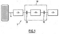
- FIG. 1 schematically shows a parallel hybrid traction chain of known type to which the invention more particularly applies.
- Such a powertrain designated by the general reference 1 comprises a transmission chain formed by a heat engine 2, a transmission unit designated by the general reference 10 and a gearbox 3 whose input is connected to the transmission unit. 10 and the output to a wheel shaft 4.
- the transmission unit 10 comprises an electric motor 11 or more generally a reversible motor, and a first clutch 12 connecting the heat engine 2 and the electric motor 11 and a second clutch 13 connecting the electric motor 11 and the gearbox 3.
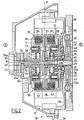
- FIG. 2 there is shown schematically the transmission module 10 which comprises the electric motor 11 formed by a stator 14 and a rotor 15 and the clutches 12 and 13.
- the electric motor 11 and the two clutches 12 and 13 as well as the connecting elements of these clutches with the heat engine 2 and / or the electric motor 3 and the control elements of said clutches which will be described later. are arranged in an internal housing of a housing designated by the general reference 20.
- the transmission unit 10 comprises an input shaft 21 formed by a sleeve 22 and a plate 23 of the first clutch 12 extending perpendicular to the axis of the sleeve 22 of the input shaft 21.
- the heat engine 2 comprises a crankshaft nose, not shown, provided with a flywheel 16 comprising a damper 17 connected to the input shaft 21 by splines 24 formed on the outer face of the sleeve 22 of the
- the transmission unit 10 also has an output shaft 25 formed by a sleeve 26 and a plate 27 of the second clutch 13 and extending perpendicular to said sleeve 26.
- the input shaft 25 is connected to a primary shaft 18 of the gearbox 3 by splines 28 formed on the inner face of the sleeve 26 of said input shaft 25.
- the sleeve 22 of the input shaft 21 and the sleeve 26 of the output shaft 25 are coaxial and the primary shaft 18 of the gearbox 3 passes through the sleeve 26 over its entire length and opens into the sleeve 22 as shown in FIG. 2.
- the plate 23 of the input shaft 21 and the plate 27 of the output shaft 25 are arranged facing one another and form a plane of symmetry "P" on either side of which is placed each of said clutches 12 and 13.
- the clutches 12 and 13 which are of wet type, are arranged on the same circumference and coaxially with the input shafts 21 and output 25.
- the stator 14 and the rotor 15 of the electric motor 11 are arranged coaxially with the clutches 12 and 13 as well as with the input and output shafts 25 and the stator 14 of this electric motor 11 is carried by a portion 20a of the casing 20.
- this part 20a of the casing 20 is situated on the same side as the first clutch 12 with respect to the plane of symmetry "P" and supports rotation an intermediate member designated as a whole by the reference 30.
- the intermediate member 30 provides the connection between the input shaft 21 and the first clutch 12 as well as the connection between the second clutch 13 and the output shaft 25.
- This intermediate member 30 is formed by a cup-shaped piece having a web 31 provided with an axial bore 31a for passage of the sleeve 22 of the passage of the input shaft 21 and a peripheral edge 32 extending around trays 23 and 27, respectively of the input shaft 21 and the output shaft 25.
- the peripheral edge 32 carries, on the side of the input shaft 21 with respect to the plane of symmetry "P", a first series of discs 33 of the first clutch 12 and, on the output shaft side 25 with respect to the plane of symmetry "P", a first series of disks 34 of the second clutch 13.
- the disks 33 and 34 are axially displaceable by translation on the inner face of the peripheral edge 32 of the intermediate member 30.
- the bore 31a of the web 31 of this intermediate member 30 is equipped with a bearing 35 for positioning said intermediate member 30 on the sleeve 22 of the input shaft 21.
- the web 31 of the intermediate member 30 comprises, on its outer face, a cylindrical extension 36 coaxial with the input shaft 21 and on which is mounted a bearing 37 of the positioning in an axial bore formed in the part 20a of the casing 20 so as to allow rotation of the intermediate member 30 carrying the rotor 15.
- the plate 23 of the input shaft 21 carries a second series of discs 38 disposed between the discs 33 of the first clutch 12 and which are also mounted on said plate 23 axially displaceable in translation.
- the discs 33 and 38 of the first clutch 12 are held tight against each other, that is to say in the engaged position, by a mechanical holding member designated by the general reference 40.
- the plate 27 of the shaft 25 carries a second series of discs 39 disposed between the discs 34 of the second clutch 13 and which are also axially displaceable. translation.
- the disks 34 and 39 of the second clutch 13 are held tight against each other, that is to say in the engaged position by a mechanical holding member designated by the general reference 50.
- the mechanical member 40 holding the discs 33 and 38 of the first clutch 12 in the engaged position comprises a control plate 41 displaceable in axial translation around the sleeve 22 of the input shaft 21 and in the direction of the plane of symmetry " P ".
- the peripheral edge of the plate 41 applies a force to the discs 33 and 38 of the first clutch 12 under the action of at least one elastic element 42.
- each elastic return element 42 is formed by a helical spring and which are six in number uniformly distributed around the sleeve 22 of the input shaft 21 and each mounted on a guide rod 43.
- the coil springs 42 exert a restoring force on the plate 41 in the direction of the plane of symmetry "P" in order to maintain the disks 33 and 38 of the first clutch 12 in the engaged position.
- the mechanical member 50 is also formed by a control plate 51 displaceable in axial translation around the sleeve 26 of the output shaft 25 and in the direction of the plane of symmetry "P" under the action of at least one element
- each elastic return element 52 is constituted, in the embodiment shown in FIG. 2, by a helical spring and which are six in number uniformly distributed around the sleeve 26 of the output shaft 25.
- Each coil spring is mounted on a guide rod 53 disposed opposite a guide rod 43 of a coil spring 42 of the first clutch 12.
- the transmission unit 10 also comprises a hydraulic control circuit in the disengaged position of each of the clutches 12 and 13.
- the hydraulic control circuit of the first clutch 12 comprises an axial channel 60 formed in the primary shaft 18 of the gearbox 3 and having a first end 60a connected to a fluid supply under pressure, not shown, and a second end 60b connected by a transverse bore 61 formed in the sleeve 22 of the input shaft 21 to a chamber 62 disposed between the plate 23 of the input shaft 21 and the control plate 41 of the first clutch 12.
- the chamber 63 is delimited by a piston 63 concentric with the sleeve 22 of the input shaft 21 and which acts on the control plate 41.
- the hydraulic control circuit of the second clutch 13 comprises an axial channel 70 formed in the primary shaft 18 of the gearbox 3 and extending parallel to the axial channel 60.
- the axial channel 70 has a first end 70a connected to a power supply fluid pressure, not shown, and a second end 70b connected by a transverse bore 71 formed in the sleeve 26 of the output shaft 25 to a chamber 72 disposed between the plate 27 of the input shaft 25 and the tray control unit 51 of the second clutch 13.
- the chamber 72 is delimited on one side by a piston 73 concentric with the sleeve 26 of the input shaft 25 and which acts on the control plate 51 under the effect of the pressure of the hydraulic fluid admitted into said chamber 72.
- the vehicle can move in hybrid mode, that is to say with the heat engine 2 and the electric motor 11.
- the heat engine 2 and the electric motor 11 are linked for example to recharge, by said engine 2, the battery connected to the electric motor 11 or to start the engine 2 by the electric motor 11.
- the heat engine 2 and the electric machine 11 are uncoupled from the gearbox 3 and thus the wheels of the motor vehicle.
- the electric motor 11 and the gearbox 3 are connected for example to drive in pure electric mode if the first clutch 12 is in the open position, it is to say in the disengaged position under the effect of the hydraulic fluid admitted into the chamber 63 through the axial passage 60 or to recover in electrical form kinetic energy of the vehicle in deceleration or braking.
- the transmission unit according to the invention has the advantage of being particularly compact because of the implementation of the various components of this transmission unit so that it can easily adapt to a single-source traction chain. conventional, and substitute for a simple clutch, to form a parallel hybrid type power train, without major modification of the other elements of the power train.
- the part of the housing supporting the stator of the electric motor also acts as a tight separation between a moist environment constituted by the interior of the housing and a dry environment outside the housing and this part also supports the rolling of rotor positioning of the electric motor.
Landscapes
- Engineering & Computer Science (AREA)
- Mechanical Engineering (AREA)
- General Engineering & Computer Science (AREA)
- Chemical & Material Sciences (AREA)
- Combustion & Propulsion (AREA)
- Transportation (AREA)
- Hybrid Electric Vehicles (AREA)
- Hydraulic Clutches, Magnetic Clutches, Fluid Clutches, And Fluid Joints (AREA)
- Automobile Manufacture Line, Endless Track Vehicle, Trailer (AREA)
- Arrangement Of Transmissions (AREA)
- Devices For Conveying Motion By Means Of Endless Flexible Members (AREA)
- Transmissions By Endless Flexible Members (AREA)
- Arrangement And Driving Of Transmission Devices (AREA)
Claims (15)
- Kraftübertragungseinheit für einen Antriebsstrang einer Antriebsmotorbaugruppe des Parallelhybrid-Typs, insbesondere für Kraftfahrzeuge, wobei die Einheit (10) eine Antriebswelle (21), die dazu bestimmt ist, mit einer Brennkraftmaschine (2) verbunden zu werden, und eine Abtriebswelle (25), die dazu bestimmt ist, mit einem Schaltgetriebe (3) verbunden zu werden, einen Elektromotor (11), der einen Stator (14) und einen Rotor (15) enthält, eine erste Kupplung (12) für die Verbindung der Antriebswelle (21) mit einem Zwischenorgan (30) und eine zweite Kupplung (13) für die Verbindung des Zwischenorgans (30) mit der Abtriebswelle (25) umfasst, wobei das Zwischenorgan (30) mit dem Rotor (15) drehbar verbunden ist, dadurch gekennzeichnet, dass die zwei Kupplungen (12, 13) auf demselben Umfang koaxial zu der Antriebswelle (21) und der Abtriebswelle (25), zum Stator (14) und zum Rotor (15) des Elektromotors (11) angeordnet sind und dass der Stator (14) von einem Teil (20a) eines Gehäuses (20) getragen wird, das das Zwischenorgan (30) drehbar unterstützt, wobei das Gehäuse (20) einen dichten Aufnahmesitz definiert, in dem der Stator (14), der Rotor (15), die zwei Kupplungen (12, 13), ein mechanisches Organ (40, 50) zum Halten jeder der Kupplungen (12, 13) in der eingerückten Stellung sowie einen Hydraulikkreis (60, 62, 70, 72) für die Steuerung jeder der Kupplungen (12, 13) in die ausgerückte Stellung angebracht sind.
- Kraftübertragungseinheit nach Anspruch 1, dadurch gekennzeichnet, dass die zwei Kupplungen (12, 13) vom Nasskupplungstyp sind
- Kraftübertragungseinheit nach Anspruch 1, dadurch gekennzeichnet, dass die Antriebswelle (21) durch eine Muffe (22) gebildet ist, die an einem ersten Ende Rillen (24) für die Verbindung mit einem mit der Brennkraftmaschine (2) verbundenen Schwungrad (16, 17) und an einem zweiten Ende eine Platte (23) der ersten Kupplung (12) aufweist.
- Kraftübertragungseinheit nach Anspruch 1, dadurch gekennzeichnet, dass die Abtriebswelle (25) durch eine Muffe (26) gebildet ist, die an einem ersten Ende Rillen (28) für die Verbindung mit einer Hauptwelle (18) des Schaltgetriebes (3) und an einem zweiten Ende eine Platte (27) der zweiten Kupplung (13) aufweist.
- Kraftübertragungseinheit nach Anspruch 3 oder 4, dadurch gekennzeichnet, dass die Platten (23, 27) einander gegenüber angeordnet sind und eine Symmetrieebene bilden, auf deren beiden Seiten jeweils eine der Kupplungen (12, 13) angeordnet ist.
- Kraftübertragungseinheit nach einem der vorhergehenden Ansprüche, dadurch gekennzeichnet, dass das Zwischenorgan (30) ein Teil in Form eines Bechers umfasst, der einerseits eine mit einer axialen Bohrung (31a) für den Durchgang der Muffe (22) der Antriebswelle (21) versehene Abdeckung (31) und andererseits einen Umfangsrand (32), der sich um die zwei Platten (23, 27) erstreckt und auf seiner Außenfläche eine erste Reihe von Scheiben (33) der ersten Kupplung (12) und eine zweite Reihe von Scheiben (34) der zweiten Kupplung trägt,
- Kraftübertragungseinheit nach Anspruch 6, dadurch gekennzeichnet, dass die Bohrung (31a) der Abdeckung (31) des Zwischenorgans (30) mit einem Wälzlager (37) für die Positionierung in einer in dem Gehäuse (20) ausgebildeten axialen Bohrung trägt.
- Kraftübertragungseinheit nach Anspruch 6 oder 7, dadurch gekennzeichnet, dass die Abdeckung (31) des Zwischenorgans (30) auf ihrer Außenseite eine zylindrische Verlängerung (36) aufweist, die ein Lager (37) für die Positionierung in einer in dem Gehäuse (20) ausgebildeten axialen Bohrung trägt.
- Kraftübertragungseinheit nach einem der Ansprüche 1 bis 8, dadurch gekennzeichnet, dass die Platte (23) der Antriebswelle (21) eine zweite Reihe von Scheiben (38) der ersten Kupplung (12) trägt, die zwischen den Scheiben (33) der ersten Reihe angeordnet sind, wobei die Scheiben (33, 38) der ersten Kupplung (12) axial translatorisch verlagerbar sind und unter der Wirkung des mechanischen Halteorgans (40) zueinander zurückgestellt werden.
- Kraftübertragungseinheit nach einem der Ansprüche 1 bis 8, dadurch gekennzeichnet, dass die Platte (27) der Muffe (26) der Abtriebswelle (25) eine zweite Reihe von Scheiben (39) der zweiten Kupplung (13) trägt, die zwischen den Scheiben (34) der ersten Reihe angeordnet sind, wobei die Scheiben (34, 39) der zweiten Kupplung (13) axial translatorisch verlagerbar sind und unter der Wirkung des mechanischen Halteorgans (50) zueinander zurückgestellt werden.
- Kraftübertragungseinheit nach einem der Ansprüche 1 bis 10, dadurch gekennzeichnet, dass das mechanische Halteorgan (40) der ersten Kupplung (12) in der eingerückten Position eine Steuerplatte (41) umfasst, die axial translatorisch um die Muffe (22) der Antriebswelle (21) und in Richtung der Symmetrieebene unter der Wirkung wenigstens eines elastischen Rückstellelements (42) verlagerbar ist, um die Scheiben (33, 38) der ersten Kupplung (12) gegeneinander gedrückt zu halten.
- Kraftübertragungseinheit nach einem der Ansprüche 1 bis 10, dadurch gekennzeichnet, dass das mechanische Halteorgan (50) der zweiten Kupplung (13) in der eingerückten Stellung eine Platte (51) umfasst, die axial translatorisch um die Muffe (26) der Abtriebswelle (25) und in der Richtung der Symmetrieebene unter der Wirkung wenigstens eines elastischen Rückstellelements (52) verlagerbar ist, um die Scheiben (34, 39) der zweiten Kupplung (13) gegeneinander gedrückt zu halten.
- Kraftübertragungseinheit nach einem der Ansprüche 1 bis 11, dadurch gekennzeichnet, dass der Hydrauliksteuerkreis der ersten Kupplung (12) einen axialen Kanal (60) umfasst, der in der Hauptwelle (18) des Schaltgetriebes (3) ausgebildet ist und ein erstes Ende (60a), das mit einer Versorgung für mit Druck beaufschlagtes Fluid verbunden ist, und ein zweites Ende (60b), das über eine transversale Durchlochung (61), die in der Muffe (22) der Antriebswelle (21) ausgebildet ist, mit einer Kammer (62) verbunden ist, die zwischen der Platte (23) der Antriebswelle (21) und der Steuerplatte (41) der ersten Kupplung (12) angeordnet ist, umfasst.
- Kraftübertragmagseinheit nach einem der Ansprüche 1 bis 10 und 12, dadurch gekennzeichnet, dass der Hydraulikkreis der zweiten Kupplung (13) einen axialen Kanal (70) umfasst, der in der Hauptwelle (18) des Schaltgetriebes (3) ausgebildet ist und ein erstes Ende (70a), das mit einer Versorgung für mit Druck beaufschlagtes Fluid verbunden ist, und ein zweites Ende (70b), das über eine transversale Durchlochung (71), die in der Muffe (26) der Abtriebswelle (25) ausgebildet ist, mit einer Kammer (72) verbunden ist, die zwischen der Platte (27) der Antriebswelle (25) und der Steuerplatte (51) der zweiten Kupplung (13) angeordnet ist, umfasst.
- Kraftfahrzeug, das einen Antriebsstrang des Parallelhybrid-Typs enthält, wobei der Antriebsstrang eine Brennkraftmaschine (2), ein Schaltgetriebe (3) und eine Kraftübertragungseinheit (10) nach einem der vorhergehenden Ansprüche, die die Brennkraftmaschine (2) mit dem Schaltgetriebe (3) verbindet, umfasst.
Applications Claiming Priority (2)
| Application Number | Priority Date | Filing Date | Title |
|---|---|---|---|
| FR0313154 | 2003-11-07 | ||
| FR0313154A FR2862026B1 (fr) | 2003-11-07 | 2003-11-07 | Unite de transmission pour une chaine de traction d'un groupe motopropulseur de vehicules automobiles |
Publications (2)
| Publication Number | Publication Date |
|---|---|
| EP1529673A1 EP1529673A1 (de) | 2005-05-11 |
| EP1529673B1 true EP1529673B1 (de) | 2006-07-26 |
Family
ID=34429965
Family Applications (1)
| Application Number | Title | Priority Date | Filing Date |
|---|---|---|---|
| EP04292623A Expired - Lifetime EP1529673B1 (de) | 2003-11-07 | 2004-11-04 | Übertragungseinheit für einen Antriebsstrang eines Antriebsaggregats von Kraftfahrzeugen |
Country Status (5)
| Country | Link |
|---|---|
| EP (1) | EP1529673B1 (de) |
| AT (1) | ATE334010T1 (de) |
| DE (1) | DE602004001652T2 (de) |
| ES (1) | ES2268595T3 (de) |
| FR (1) | FR2862026B1 (de) |
Families Citing this family (10)
| Publication number | Priority date | Publication date | Assignee | Title |
|---|---|---|---|---|
| EP1736345A1 (de) * | 2005-06-22 | 2006-12-27 | Zf Friedrichshafen Ag | Elektromotorisches Antriebsmodul |
| DE102005040771A1 (de) * | 2005-08-29 | 2007-03-08 | Zf Friedrichshafen Ag | Antriebsstrang eines Hybridfahrzeuges |
| DE102006055541A1 (de) * | 2006-11-24 | 2008-09-04 | Volkswagen Ag | Hybridantriebssystem für ein Fahrzeug |
| DE102007002611A1 (de) * | 2007-01-12 | 2008-07-24 | Voith Patent Gmbh | Hybridantriebseinheit mit einer Verbrennungskraftmaschine und einem Dampfmotor |
| DE102008000363A1 (de) | 2008-02-21 | 2009-08-27 | Zf Friedrichshafen Ag | Hybridantriebsstrang eines Kraftfahrzeugs |
| DE102008040496A1 (de) * | 2008-07-17 | 2010-01-21 | Zf Friedrichshafen Ag | Verfahren zur Kühlung einer elektrischen Maschine in einem Hybridantriebsstrang eines Kraftfahrzeugs |
| DE102008062183A1 (de) | 2008-12-13 | 2010-06-17 | Dr. Ing. H.C. F. Porsche Aktiengesellschaft | Verfahren zum Betreiben eines Hybridfahrzeuges |
| JP5434514B2 (ja) * | 2009-11-19 | 2014-03-05 | アイシン精機株式会社 | ハイブリッド車両用駆動装置 |
| CN106891714B (zh) * | 2017-01-23 | 2023-10-20 | 中国第一汽车股份有限公司 | 一种机动车用三离合机电耦合驱动装置 |
| CN111886783B (zh) * | 2018-03-28 | 2023-12-01 | 株式会社爱信 | 车辆用驱动装置 |
Family Cites Families (4)
| Publication number | Priority date | Publication date | Assignee | Title |
|---|---|---|---|---|
| US6585066B1 (en) * | 2000-05-09 | 2003-07-01 | Ford Global Technologies, Llc | Motor/alternator with integral wet clutch for use in hybrid vehicles |
| DE10140366A1 (de) * | 2001-03-27 | 2003-07-17 | May Heinz | Hybridantriebe für Kraftfahrzeuge |
| DE10140424A1 (de) * | 2001-08-17 | 2003-02-27 | Zahnradfabrik Friedrichshafen | Automatisch schaltbares Fahrzeuggetriebe |
| GB2386653B (en) * | 2002-03-22 | 2005-06-29 | Gkn Technology Ltd | Differential gear |
-
2003
- 2003-11-07 FR FR0313154A patent/FR2862026B1/fr not_active Expired - Fee Related
-
2004
- 2004-11-04 ES ES04292623T patent/ES2268595T3/es not_active Expired - Lifetime
- 2004-11-04 EP EP04292623A patent/EP1529673B1/de not_active Expired - Lifetime
- 2004-11-04 AT AT04292623T patent/ATE334010T1/de not_active IP Right Cessation
- 2004-11-04 DE DE602004001652T patent/DE602004001652T2/de not_active Expired - Lifetime
Also Published As
| Publication number | Publication date |
|---|---|
| DE602004001652T2 (de) | 2007-07-19 |
| EP1529673A1 (de) | 2005-05-11 |
| FR2862026A1 (fr) | 2005-05-13 |
| ES2268595T3 (es) | 2007-03-16 |
| DE602004001652D1 (de) | 2006-09-07 |
| ATE334010T1 (de) | 2006-08-15 |
| FR2862026B1 (fr) | 2006-02-17 |
Similar Documents
| Publication | Publication Date | Title |
|---|---|---|
| EP1750968B1 (de) | Doppelkupplungsgetriebeelement für einen hybridantriebsstrang eines kraftfahrzeuges, verfahren zu dessen montage und kraftfahrzeug mit derartigem element | |
| EP1750966B1 (de) | Übertragungselement für einen parallelen hybridantriebsstrang | |
| EP3532324B1 (de) | Getriebevorrichtung für hybridfahrzeug | |
| WO2021099070A1 (fr) | Moyeu d'alimentation d'huile assemblé et triple embrayage humide comprenant ce moyeu d'alimentation d'huile assemblé | |
| EP1868832B1 (de) | Hybridantriebskette und damit ausgestattetes hybridfahrzeug | |
| EP3879133B1 (de) | Doppelnasskupplung | |
| FR2862026A1 (fr) | Unite de transmission pour une chaine de traction d'un groupe motopropulseur de vehicules automobiles | |
| FR3052401B1 (fr) | Dispositif de transmission de couple, notamment pour vehicule automobile | |
| FR3090774A1 (fr) | Dispositif de transmission pour véhicule automobile | |
| FR2790530A1 (fr) | Unite de transmission de couple de rotation | |
| WO2021239693A1 (fr) | Double embrayage humide de type multidisques | |
| EP4380810B1 (de) | Antriebsstrang für ein hybrid-antriebs- oder zugkraftfahrzeug mit einem mechanismus zum blockieren des verbrennungsmotors | |
| FR2862025A1 (fr) | Element de transmission a double embrayage pour chaine de traction hybride de vehicule automobile equipe d'un tel element | |
| FR2829814A1 (fr) | Reducteur a train epicycloidal notamment pour demarreur de vehicule automobile et demarreur equipe d'un tel reducteur | |
| WO2019211244A1 (fr) | Dispositif de transmission pour vehicule automobile | |
| WO2019201472A1 (fr) | Systeme d'entrainement pour un vehicule automobile hybride et systeme de transmission comprenant un tel systeme d'entrainement | |
| EP3710298A1 (de) | Getriebevorrichtung für hybridfahrzeug | |
| WO2019102098A2 (fr) | Dispositif de transmission pour véhicule hybride | |
| EP4046843A1 (de) | Antriebsmodul, hybride unterantriebseinheit eines fahrzeugs und verfahren zum schliessen einer klauenkupplung | |
| WO2019166516A1 (fr) | Dispositif de transmission pour vehicule hybride | |
| FR3090773A1 (fr) | Dispositif de transmission pour véhicule automobile | |
| FR2886998A1 (fr) | Mecanisme d'embrayages multiples avec butee a grands debattements | |
| FR3071889B1 (fr) | Systeme d'embrayage comportant un plateau de reaction supporte par un organe d'entree | |
| FR3080896A1 (fr) | Dispositif de transmission pour vehicule automobile | |
| FR3080898A1 (fr) | Dispositif de transmission pour vehicule automobile |
Legal Events
| Date | Code | Title | Description |
|---|---|---|---|
| PUAI | Public reference made under article 153(3) epc to a published international application that has entered the european phase |
Free format text: ORIGINAL CODE: 0009012 |
|
| AK | Designated contracting states |
Kind code of ref document: A1 Designated state(s): AT BE BG CH CY CZ DE DK EE ES FI FR GB GR HU IE IS IT LI LU MC NL PL PT RO SE SI SK TR |
|
| AX | Request for extension of the european patent |
Extension state: AL HR LT LV MK YU |
|
| RIN1 | Information on inventor provided before grant (corrected) |
Inventor name: VICTOR, JEROEME Inventor name: DELPORTE, STEPHANE Inventor name: CHAPELON, LIONEL |
|
| 17P | Request for examination filed |
Effective date: 20051020 |
|
| AKX | Designation fees paid |
Designated state(s): AT BE BG CH CY CZ DE DK EE ES FI FR GB GR HU IE IS IT LI LU MC NL PL PT RO SE SI SK TR |
|
| GRAP | Despatch of communication of intention to grant a patent |
Free format text: ORIGINAL CODE: EPIDOSNIGR1 |
|
| GRAS | Grant fee paid |
Free format text: ORIGINAL CODE: EPIDOSNIGR3 |
|
| GRAA | (expected) grant |
Free format text: ORIGINAL CODE: 0009210 |
|
| AK | Designated contracting states |
Kind code of ref document: B1 Designated state(s): AT BE BG CH CY CZ DE DK EE ES FI FR GB GR HU IE IS IT LI LU MC NL PL PT RO SE SI SK TR |
|
| PG25 | Lapsed in a contracting state [announced via postgrant information from national office to epo] |
Ref country code: IT Free format text: LAPSE BECAUSE OF FAILURE TO SUBMIT A TRANSLATION OF THE DESCRIPTION OR TO PAY THE FEE WITHIN THE PRESCRIBED TIME-LIMIT;WARNING: LAPSES OF ITALIAN PATENTS WITH EFFECTIVE DATE BEFORE 2007 MAY HAVE OCCURRED AT ANY TIME BEFORE 2007. THE CORRECT EFFECTIVE DATE MAY BE DIFFERENT FROM THE ONE RECORDED. Effective date: 20060726 Ref country code: IS Free format text: LAPSE BECAUSE OF FAILURE TO SUBMIT A TRANSLATION OF THE DESCRIPTION OR TO PAY THE FEE WITHIN THE PRESCRIBED TIME-LIMIT Effective date: 20060726 Ref country code: SK Free format text: LAPSE BECAUSE OF FAILURE TO SUBMIT A TRANSLATION OF THE DESCRIPTION OR TO PAY THE FEE WITHIN THE PRESCRIBED TIME-LIMIT Effective date: 20060726 Ref country code: SI Free format text: LAPSE BECAUSE OF FAILURE TO SUBMIT A TRANSLATION OF THE DESCRIPTION OR TO PAY THE FEE WITHIN THE PRESCRIBED TIME-LIMIT Effective date: 20060726 Ref country code: PL Free format text: LAPSE BECAUSE OF FAILURE TO SUBMIT A TRANSLATION OF THE DESCRIPTION OR TO PAY THE FEE WITHIN THE PRESCRIBED TIME-LIMIT Effective date: 20060726 Ref country code: FI Free format text: LAPSE BECAUSE OF FAILURE TO SUBMIT A TRANSLATION OF THE DESCRIPTION OR TO PAY THE FEE WITHIN THE PRESCRIBED TIME-LIMIT Effective date: 20060726 Ref country code: RO Free format text: LAPSE BECAUSE OF FAILURE TO SUBMIT A TRANSLATION OF THE DESCRIPTION OR TO PAY THE FEE WITHIN THE PRESCRIBED TIME-LIMIT Effective date: 20060726 Ref country code: IE Free format text: LAPSE BECAUSE OF FAILURE TO SUBMIT A TRANSLATION OF THE DESCRIPTION OR TO PAY THE FEE WITHIN THE PRESCRIBED TIME-LIMIT Effective date: 20060726 Ref country code: AT Free format text: LAPSE BECAUSE OF FAILURE TO SUBMIT A TRANSLATION OF THE DESCRIPTION OR TO PAY THE FEE WITHIN THE PRESCRIBED TIME-LIMIT Effective date: 20060726 Ref country code: CZ Free format text: LAPSE BECAUSE OF FAILURE TO SUBMIT A TRANSLATION OF THE DESCRIPTION OR TO PAY THE FEE WITHIN THE PRESCRIBED TIME-LIMIT Effective date: 20060726 Ref country code: NL Free format text: LAPSE BECAUSE OF FAILURE TO SUBMIT A TRANSLATION OF THE DESCRIPTION OR TO PAY THE FEE WITHIN THE PRESCRIBED TIME-LIMIT Effective date: 20060726 |
|
| REG | Reference to a national code |
Ref country code: GB Ref legal event code: FG4D Free format text: NOT ENGLISH |
|
| REG | Reference to a national code |
Ref country code: CH Ref legal event code: EP |
|
| REG | Reference to a national code |
Ref country code: IE Ref legal event code: FG4D Free format text: LANGUAGE OF EP DOCUMENT: FRENCH |
|
| REF | Corresponds to: |
Ref document number: 602004001652 Country of ref document: DE Date of ref document: 20060907 Kind code of ref document: P |
|
| PG25 | Lapsed in a contracting state [announced via postgrant information from national office to epo] |
Ref country code: SE Free format text: LAPSE BECAUSE OF FAILURE TO SUBMIT A TRANSLATION OF THE DESCRIPTION OR TO PAY THE FEE WITHIN THE PRESCRIBED TIME-LIMIT Effective date: 20061026 Ref country code: DK Free format text: LAPSE BECAUSE OF FAILURE TO SUBMIT A TRANSLATION OF THE DESCRIPTION OR TO PAY THE FEE WITHIN THE PRESCRIBED TIME-LIMIT Effective date: 20061026 Ref country code: BG Free format text: LAPSE BECAUSE OF FAILURE TO SUBMIT A TRANSLATION OF THE DESCRIPTION OR TO PAY THE FEE WITHIN THE PRESCRIBED TIME-LIMIT Effective date: 20061026 |
|
| GBT | Gb: translation of ep patent filed (gb section 77(6)(a)/1977) |
Effective date: 20061017 |
|
| PG25 | Lapsed in a contracting state [announced via postgrant information from national office to epo] |
Ref country code: MC Free format text: LAPSE BECAUSE OF NON-PAYMENT OF DUE FEES Effective date: 20061130 Ref country code: BE Free format text: LAPSE BECAUSE OF NON-PAYMENT OF DUE FEES Effective date: 20061130 |
|
| PG25 | Lapsed in a contracting state [announced via postgrant information from national office to epo] |
Ref country code: PT Free format text: LAPSE BECAUSE OF FAILURE TO SUBMIT A TRANSLATION OF THE DESCRIPTION OR TO PAY THE FEE WITHIN THE PRESCRIBED TIME-LIMIT Effective date: 20061226 |
|
| NLV1 | Nl: lapsed or annulled due to failure to fulfill the requirements of art. 29p and 29m of the patents act | ||
| REG | Reference to a national code |
Ref country code: IE Ref legal event code: FD4D |
|
| REG | Reference to a national code |
Ref country code: ES Ref legal event code: FG2A Ref document number: 2268595 Country of ref document: ES Kind code of ref document: T3 |
|
| PLBE | No opposition filed within time limit |
Free format text: ORIGINAL CODE: 0009261 |
|
| STAA | Information on the status of an ep patent application or granted ep patent |
Free format text: STATUS: NO OPPOSITION FILED WITHIN TIME LIMIT |
|
| 26N | No opposition filed |
Effective date: 20070427 |
|
| BERE | Be: lapsed |
Owner name: PEUGEOT CITROEN AUTOMOBILES S.A. Effective date: 20061130 |
|
| PG25 | Lapsed in a contracting state [announced via postgrant information from national office to epo] |
Ref country code: GR Free format text: LAPSE BECAUSE OF FAILURE TO SUBMIT A TRANSLATION OF THE DESCRIPTION OR TO PAY THE FEE WITHIN THE PRESCRIBED TIME-LIMIT Effective date: 20061027 |
|
| PG25 | Lapsed in a contracting state [announced via postgrant information from national office to epo] |
Ref country code: EE Free format text: LAPSE BECAUSE OF FAILURE TO SUBMIT A TRANSLATION OF THE DESCRIPTION OR TO PAY THE FEE WITHIN THE PRESCRIBED TIME-LIMIT Effective date: 20060726 |
|
| PG25 | Lapsed in a contracting state [announced via postgrant information from national office to epo] |
Ref country code: TR Free format text: LAPSE BECAUSE OF FAILURE TO SUBMIT A TRANSLATION OF THE DESCRIPTION OR TO PAY THE FEE WITHIN THE PRESCRIBED TIME-LIMIT Effective date: 20060726 Ref country code: HU Free format text: LAPSE BECAUSE OF FAILURE TO SUBMIT A TRANSLATION OF THE DESCRIPTION OR TO PAY THE FEE WITHIN THE PRESCRIBED TIME-LIMIT Effective date: 20070127 Ref country code: LU Free format text: LAPSE BECAUSE OF NON-PAYMENT OF DUE FEES Effective date: 20061104 |
|
| PG25 | Lapsed in a contracting state [announced via postgrant information from national office to epo] |
Ref country code: CY Free format text: LAPSE BECAUSE OF FAILURE TO SUBMIT A TRANSLATION OF THE DESCRIPTION OR TO PAY THE FEE WITHIN THE PRESCRIBED TIME-LIMIT Effective date: 20060726 |
|
| REG | Reference to a national code |
Ref country code: CH Ref legal event code: PL |
|
| PG25 | Lapsed in a contracting state [announced via postgrant information from national office to epo] |
Ref country code: LI Free format text: LAPSE BECAUSE OF NON-PAYMENT OF DUE FEES Effective date: 20081130 Ref country code: CH Free format text: LAPSE BECAUSE OF NON-PAYMENT OF DUE FEES Effective date: 20081130 |
|
| REG | Reference to a national code |
Ref country code: ES Ref legal event code: GC2A Effective date: 20110202 |
|
| PGFP | Annual fee paid to national office [announced via postgrant information from national office to epo] |
Ref country code: DE Payment date: 20121025 Year of fee payment: 9 |
|
| PGFP | Annual fee paid to national office [announced via postgrant information from national office to epo] |
Ref country code: GB Payment date: 20121025 Year of fee payment: 9 Ref country code: IT Payment date: 20121025 Year of fee payment: 9 Ref country code: ES Payment date: 20121023 Year of fee payment: 9 |
|
| PGFP | Annual fee paid to national office [announced via postgrant information from national office to epo] |
Ref country code: FR Payment date: 20130107 Year of fee payment: 9 |
|
| REG | Reference to a national code |
Ref country code: DE Ref legal event code: R119 Ref document number: 602004001652 Country of ref document: DE |
|
| REG | Reference to a national code |
Ref country code: DE Ref legal event code: R079 Ref document number: 602004001652 Country of ref document: DE Free format text: PREVIOUS MAIN CLASS: B60K0006040000 Ipc: B60K0006000000 |
|
| GBPC | Gb: european patent ceased through non-payment of renewal fee |
Effective date: 20131104 |
|
| REG | Reference to a national code |
Ref country code: FR Ref legal event code: ST Effective date: 20140731 |
|
| REG | Reference to a national code |
Ref country code: DE Ref legal event code: R119 Ref document number: 602004001652 Country of ref document: DE Effective date: 20140603 Ref country code: DE Ref legal event code: R079 Ref document number: 602004001652 Country of ref document: DE Free format text: PREVIOUS MAIN CLASS: B60K0006040000 Ipc: B60K0006000000 Effective date: 20140722 |
|
| PG25 | Lapsed in a contracting state [announced via postgrant information from national office to epo] |
Ref country code: DE Free format text: LAPSE BECAUSE OF NON-PAYMENT OF DUE FEES Effective date: 20140603 Ref country code: IT Free format text: LAPSE BECAUSE OF NON-PAYMENT OF DUE FEES Effective date: 20131104 |
|
| PG25 | Lapsed in a contracting state [announced via postgrant information from national office to epo] |
Ref country code: FR Free format text: LAPSE BECAUSE OF NON-PAYMENT OF DUE FEES Effective date: 20131202 Ref country code: GB Free format text: LAPSE BECAUSE OF NON-PAYMENT OF DUE FEES Effective date: 20131104 |
|
| REG | Reference to a national code |
Ref country code: ES Ref legal event code: FD2A Effective date: 20150327 |
|
| PG25 | Lapsed in a contracting state [announced via postgrant information from national office to epo] |
Ref country code: ES Free format text: LAPSE BECAUSE OF NON-PAYMENT OF DUE FEES Effective date: 20131105 |