EP1529628A1 - Vorrichtung zum Aufrichten von Schachteln - Google Patents
Vorrichtung zum Aufrichten von Schachteln Download PDFInfo
- Publication number
- EP1529628A1 EP1529628A1 EP04256732A EP04256732A EP1529628A1 EP 1529628 A1 EP1529628 A1 EP 1529628A1 EP 04256732 A EP04256732 A EP 04256732A EP 04256732 A EP04256732 A EP 04256732A EP 1529628 A1 EP1529628 A1 EP 1529628A1
- Authority
- EP
- European Patent Office
- Prior art keywords
- tote container
- tote
- flap members
- surface flap
- workpieces
- Prior art date
- Legal status (The legal status is an assumption and is not a legal conclusion. Google has not performed a legal analysis and makes no representation as to the accuracy of the status listed.)
- Withdrawn
Links
- 230000007246 mechanism Effects 0.000 claims description 83
- 238000002360 preparation method Methods 0.000 claims description 9
- 238000000034 method Methods 0.000 description 39
- 230000008569 process Effects 0.000 description 15
- 230000003014 reinforcing effect Effects 0.000 description 14
- 229920001169 thermoplastic Polymers 0.000 description 12
- 239000004416 thermosoftening plastic Substances 0.000 description 12
- 230000015572 biosynthetic process Effects 0.000 description 7
- 238000006073 displacement reaction Methods 0.000 description 7
- 239000012815 thermoplastic material Substances 0.000 description 6
- 239000008186 active pharmaceutical agent Substances 0.000 description 5
- 230000001010 compromised effect Effects 0.000 description 4
- 230000000717 retained effect Effects 0.000 description 3
- 230000009977 dual effect Effects 0.000 description 2
- 230000000694 effects Effects 0.000 description 2
- 239000007795 chemical reaction product Substances 0.000 description 1
- 238000012790 confirmation Methods 0.000 description 1
- 230000003993 interaction Effects 0.000 description 1
- 239000000047 product Substances 0.000 description 1
- 238000000926 separation method Methods 0.000 description 1
- 230000009466 transformation Effects 0.000 description 1
Images



Classifications
-
- B—PERFORMING OPERATIONS; TRANSPORTING
- B65—CONVEYING; PACKING; STORING; HANDLING THIN OR FILAMENTARY MATERIAL
- B65D—CONTAINERS FOR STORAGE OR TRANSPORT OF ARTICLES OR MATERIALS, e.g. BAGS, BARRELS, BOTTLES, BOXES, CANS, CARTONS, CRATES, DRUMS, JARS, TANKS, HOPPERS, FORWARDING CONTAINERS; ACCESSORIES, CLOSURES, OR FITTINGS THEREFOR; PACKAGING ELEMENTS; PACKAGES
- B65D5/00—Rigid or semi-rigid containers of polygonal cross-section, e.g. boxes, cartons or trays, formed by folding or erecting one or more blanks made of paper
- B65D5/36—Rigid or semi-rigid containers of polygonal cross-section, e.g. boxes, cartons or trays, formed by folding or erecting one or more blanks made of paper specially constructed to allow collapsing and re-erecting without disengagement of side or bottom connections
- B65D5/3607—Rigid or semi-rigid containers of polygonal cross-section, e.g. boxes, cartons or trays, formed by folding or erecting one or more blanks made of paper specially constructed to allow collapsing and re-erecting without disengagement of side or bottom connections formed by folding or erecting a single blank
- B65D5/3614—Rigid or semi-rigid containers of polygonal cross-section, e.g. boxes, cartons or trays, formed by folding or erecting one or more blanks made of paper specially constructed to allow collapsing and re-erecting without disengagement of side or bottom connections formed by folding or erecting a single blank to form a tubular body, at least one of the ends of the body remaining connected
- B65D5/3621—Rigid or semi-rigid containers of polygonal cross-section, e.g. boxes, cartons or trays, formed by folding or erecting one or more blanks made of paper specially constructed to allow collapsing and re-erecting without disengagement of side or bottom connections formed by folding or erecting a single blank to form a tubular body, at least one of the ends of the body remaining connected collapsed along two fold lines of the tubular body
-
- B—PERFORMING OPERATIONS; TRANSPORTING
- B31—MAKING ARTICLES OF PAPER, CARDBOARD OR MATERIAL WORKED IN A MANNER ANALOGOUS TO PAPER; WORKING PAPER, CARDBOARD OR MATERIAL WORKED IN A MANNER ANALOGOUS TO PAPER
- B31B—MAKING CONTAINERS OF PAPER, CARDBOARD OR MATERIAL WORKED IN A MANNER ANALOGOUS TO PAPER
- B31B50/00—Making rigid or semi-rigid containers, e.g. boxes or cartons
- B31B50/26—Folding sheets, blanks or webs
- B31B50/44—Folding sheets, blanks or webs by plungers moving through folding dies
-
- B—PERFORMING OPERATIONS; TRANSPORTING
- B31—MAKING ARTICLES OF PAPER, CARDBOARD OR MATERIAL WORKED IN A MANNER ANALOGOUS TO PAPER; WORKING PAPER, CARDBOARD OR MATERIAL WORKED IN A MANNER ANALOGOUS TO PAPER
- B31B—MAKING CONTAINERS OF PAPER, CARDBOARD OR MATERIAL WORKED IN A MANNER ANALOGOUS TO PAPER
- B31B50/00—Making rigid or semi-rigid containers, e.g. boxes or cartons
- B31B50/006—Controlling; Regulating; Measuring; Improving safety
-
- B—PERFORMING OPERATIONS; TRANSPORTING
- B31—MAKING ARTICLES OF PAPER, CARDBOARD OR MATERIAL WORKED IN A MANNER ANALOGOUS TO PAPER; WORKING PAPER, CARDBOARD OR MATERIAL WORKED IN A MANNER ANALOGOUS TO PAPER
- B31B—MAKING CONTAINERS OF PAPER, CARDBOARD OR MATERIAL WORKED IN A MANNER ANALOGOUS TO PAPER
- B31B50/00—Making rigid or semi-rigid containers, e.g. boxes or cartons
- B31B50/74—Auxiliary operations
- B31B50/92—Delivering
-
- B—PERFORMING OPERATIONS; TRANSPORTING
- B31—MAKING ARTICLES OF PAPER, CARDBOARD OR MATERIAL WORKED IN A MANNER ANALOGOUS TO PAPER; WORKING PAPER, CARDBOARD OR MATERIAL WORKED IN A MANNER ANALOGOUS TO PAPER
- B31B—MAKING CONTAINERS OF PAPER, CARDBOARD OR MATERIAL WORKED IN A MANNER ANALOGOUS TO PAPER
- B31B2100/00—Rigid or semi-rigid containers made by folding single-piece sheets, blanks or webs
-
- B—PERFORMING OPERATIONS; TRANSPORTING
- B31—MAKING ARTICLES OF PAPER, CARDBOARD OR MATERIAL WORKED IN A MANNER ANALOGOUS TO PAPER; WORKING PAPER, CARDBOARD OR MATERIAL WORKED IN A MANNER ANALOGOUS TO PAPER
- B31B—MAKING CONTAINERS OF PAPER, CARDBOARD OR MATERIAL WORKED IN A MANNER ANALOGOUS TO PAPER
- B31B2100/00—Rigid or semi-rigid containers made by folding single-piece sheets, blanks or webs
- B31B2100/002—Rigid or semi-rigid containers made by folding single-piece sheets, blanks or webs characterised by the shape of the blank from which they are formed
-
- B—PERFORMING OPERATIONS; TRANSPORTING
- B31—MAKING ARTICLES OF PAPER, CARDBOARD OR MATERIAL WORKED IN A MANNER ANALOGOUS TO PAPER; WORKING PAPER, CARDBOARD OR MATERIAL WORKED IN A MANNER ANALOGOUS TO PAPER
- B31B—MAKING CONTAINERS OF PAPER, CARDBOARD OR MATERIAL WORKED IN A MANNER ANALOGOUS TO PAPER
- B31B2100/00—Rigid or semi-rigid containers made by folding single-piece sheets, blanks or webs
- B31B2100/002—Rigid or semi-rigid containers made by folding single-piece sheets, blanks or webs characterised by the shape of the blank from which they are formed
- B31B2100/0022—Rigid or semi-rigid containers made by folding single-piece sheets, blanks or webs characterised by the shape of the blank from which they are formed made from tubular webs or blanks, including by tube or bottom forming operations
-
- B—PERFORMING OPERATIONS; TRANSPORTING
- B31—MAKING ARTICLES OF PAPER, CARDBOARD OR MATERIAL WORKED IN A MANNER ANALOGOUS TO PAPER; WORKING PAPER, CARDBOARD OR MATERIAL WORKED IN A MANNER ANALOGOUS TO PAPER
- B31B—MAKING CONTAINERS OF PAPER, CARDBOARD OR MATERIAL WORKED IN A MANNER ANALOGOUS TO PAPER
- B31B2120/00—Construction of rigid or semi-rigid containers
- B31B2120/30—Construction of rigid or semi-rigid containers collapsible; temporarily collapsed during manufacturing
-
- B—PERFORMING OPERATIONS; TRANSPORTING
- B31—MAKING ARTICLES OF PAPER, CARDBOARD OR MATERIAL WORKED IN A MANNER ANALOGOUS TO PAPER; WORKING PAPER, CARDBOARD OR MATERIAL WORKED IN A MANNER ANALOGOUS TO PAPER
- B31B—MAKING CONTAINERS OF PAPER, CARDBOARD OR MATERIAL WORKED IN A MANNER ANALOGOUS TO PAPER
- B31B50/00—Making rigid or semi-rigid containers, e.g. boxes or cartons
- B31B50/004—Closing boxes
-
- B—PERFORMING OPERATIONS; TRANSPORTING
- B31—MAKING ARTICLES OF PAPER, CARDBOARD OR MATERIAL WORKED IN A MANNER ANALOGOUS TO PAPER; WORKING PAPER, CARDBOARD OR MATERIAL WORKED IN A MANNER ANALOGOUS TO PAPER
- B31B—MAKING CONTAINERS OF PAPER, CARDBOARD OR MATERIAL WORKED IN A MANNER ANALOGOUS TO PAPER
- B31B50/00—Making rigid or semi-rigid containers, e.g. boxes or cartons
- B31B50/74—Auxiliary operations
- B31B50/76—Opening and distending flattened articles
- B31B50/80—Pneumatically
Definitions
- the present invention relates generally to automatic article assembly or erection apparatus, and more particularly to a new and improved apparatus or system for automatically assembling or erecting tote containers, and a corresponding method or process for practicing or implementing the assembly or erection of the tote containers, wherein, in accordance with the new and improved apparatus or system, and the corresponding method or process, for assembling or erecting the tote containers, each tote container, fabricated from a suitable thermoplastic material and originally comprising a blank which is initially pre-formed into a flattened tote container workpiece having two side walls, two end walls integrally connected to the two side walls, and four foldable flap members respectively integrally connected to the lower or bottom edge portions of the four integrally connected side and end walls, is positioned in a serial array, comprising a plurality of such tote container workpieces, which is disposed within a suitable magazine or hopper, such that each one of the plurality of tote container workpieces can be serially and individually removed from
- Tote containers are of course well-known in the container industry as comprising means for holding, storing, shipping, or displaying different or diverse types of articles or objects.
- most tote containers are fabricated from, for example, corrugated cardboard, and may comprise, for example, either a five-sided structure wherein the top of the container is open such that the contents disposed within the container are readily accessible, or alternatively, a six-sided structure wherein the top of the container must first be removed so as to in fact subsequently permit access to the contents disposed within the container.
- Corrugated cardboard tote containers have of course been utilized for years and have consistently demonstrated or exhibited sufficient, satisfactory, and adequate strength and structural integrity in connection with the performance of their basic functions, such as, for example, the holding, storing, shipping, and display of the different or diverse types of articles or objects. Corrugated cardboard tote containers, however, do have, or exhibit, several inherent operational disadvantages or drawbacks.
- the lower flap members which are integrally attached to the bottom or lower edge portions of the four side and end walls of the corrugated cardboard blank, and which must be folded upwardly and inwardly with respect to the bottom or lower edge portions of the four side and end walls of the corrugated cardboard blank in order to effectively form the bottom support surface of the tote container, must be, for example, adhesively bonded or otherwise fixedly secured together so as to ensure the fact that the tote container retains its erected structural configuration.
- the tote containers can no longer assuredly or reliably perform their intended functions, whereby the articles or objects, originally disposed within the tote containers, might spoil or otherwise deteriorate, or alternatively, the articles or objects must be removed from the compromised tote containers and transferred to or deposited within new tote containers.
- conventional, corrugated cardboard tote containers do not necessarily comprise optimally cost-effective storage, shipping, and display containers.
- tote containers such as, for example, those tote containers utilized by means of various postal or mail-handling organizations in connection with the holding, storage, or transportation of mail pieces or packages, may be fabricated from a suitable thermoplastic material, such tote containers are likewise permanently erected or assembled so as to likewise prevent, or militate against, the disassembly of the same for subsequent transportation, shipping, or conveyance to other locations, at which locations the tote containers can be re-assembled or re-erected for subsequent applications or uses.
- thermoplastic tote containers it is an object of the present invention to provide a new and improved apparatus or system for automatically assembling or erecting thermoplastic tote containers, and a corresponding method or process for practicing or implementing the assembly or erection of the thermoplastic tote containers.
- Another object of the present invention is to provide a new and improved apparatus or system for automatically assembling or erecting thermoplastic tote containers, and a corresponding method or process for practicing or implementing the assembly or erection of the thermoplastic tote containers, which effectively overcome the various operational disadvantages and drawbacks characteristic of PRIOR ART tote containers and the apparatus and methods for assembling or erecting the same.
- the present invention provides a new and improved apparatus or system for automatically assembling or erecting thermoplastic tote containers, and a corresponding method or process for practicing or implementing the assembly or erection of the thermoplastic tote containers, wherein the flap members of the tote container workpiece can be folded upwardly and inwardly, with respect to the lower or bottom edge portions of the four integrally connected side and end walls of each tote container workpiece, in accordance with a predetermined procedural sequence, whereby each tote container is automatically assembled as a result of the flap members being engaged with each other in an intermeshed, interengaged, and interlocked manner so as to structurally form the bottom support surface of the tote container.
- the present invention also provides a new and improved apparatus or system for automatically assembling or erecting thermoplastic tote containers, and a corresponding method or process for practicing or implementing the assembly or erection of the thermoplastic tote containers, wherein the flap members of the tote container workpiece can be folded upwardly and inwardly, with respect to the lower or bottom edge portions of the four integrally connected side and end walls of each tote container workpiece, in accordance with a predetermined procedural sequence, whereby each tote container is automatically assembled as a result of the flap members being engaged with each other in an intermeshed, interengaged, and interlocked manner so as to structurally form the bottom support surface of the tote container without the need for fixing, bonding, or otherwise permanently securing the flap members together.
- the present invention further provides a new and improved apparatus or system for automatically assembling or erecting thermoplastic tote containers, and a corresponding method or process for practicing or implementing the assembly or erection of the thermoplastic tote containers, wherein the flap members of the tote container workpiece can be folded upwardly and inwardly, with respect to the lower or bottom edge portions of the four integrally connected side and end walls of each tote container workpiece, in accordance with a predetermined procedural sequence, whereby each tote container is automatically assembled as a result of the flap members being engaged with each other in an intermeshed, interengaged, and interlocked manner so as to structurally form the bottom support surface of the tote container without the need for fixing, bonding, or otherwise permanently securing the flap members together whereby each tote container is then capable of being used, and as may be subsequently desired or required, disassembled and reused.
- each tote container is automatically assembled as a result of the flap members being engaged with each other in an intermeshed, interengaged, and interlocked manner so as to effectively form the bottom support surface of the tote container without the need for fixing, bonding, or otherwise permanently securing the flap members together.
- each tote container is then capable of being used, and as may be subsequently desired or required, in view of the fact that the flap members are not fixed, bonded, or otherwise permanently secured together, the tote containers may be readily disassembled by disengaging or unlocking the flap members from or with respect to each other.
- the disassembled tote containers can be shipped to other locations at which, for example, the tote containers can be reused, or alternatively, the disassembled tote containers can effectively be recycled as a result of the thermoplastic tote containers being melted and re-fabricated when, for example, the structural integrity of the original tote containers may be compromised as a result of the original tote containers having effectively reached the ends of their service lives.
- a tote container blank is disclosed and is generally indicated by the reference character 10. It is to be understood that the tote container blank 10 is to be assembled, in a manner to be discussed shortly hereinafter, into a tote container workpiece 11 as disclosed within Figure 2, and in turn, the tote container workpiece 11 will be assembled into a tote container by means of the new and improved apparatus or system of the present invention, and in accordance with the assembly method of the present invention, as will also be discussed shortly hereinafter.
- the tote container blank 10 comprises a first rectangular side wall 12, a first rectangular end wall 14, a second rectangular side wall 16, and a second rectangular end wall 18. It is additionally seen that the second end wall 18 has a vertically oriented flap member 20 integrally connected thereto along a first vertically oriented score line 22, and in a similar manner, it is likewise appreciated that the first rectangular side wall 12 is integrally connected to the first rectangular end wall 14 along a second vertically oriented score line 24, the first rectangular end wall 14 is integrally connected to the second rectangular side wall 16 along a third vertically oriented score line 26, and the second rectangular side wall 16 is integrally connected to the second rectangular end wall 18 along a fourth vertically oriented score line 28.
- the tote container blank 10 is adapted to be assembled together so as to effectively form the tote container workpiece 11 as disclosed within Figure 2, and when the tote container workpiece 11 is disposed in its expanded or opened state, by means of the new and improved apparatus or system of the present invention, and in accordance with the assembly method of the present invention, the tote container workpiece 11 will have a substantially rectangular parallelepiped configuration. Accordingly, when the tote container blank 10 is assembled together so as to form the tote container workpiece 11, the external surface of the end flap member 20 will be, for example, adhesively bonded to the internal right side surface portion of the first rectangular side wall 12, as is shown in phantom at 20' in Figure 1.
- the first rectangular side wall 12 has a first reinforcing flap member 30 integrally connected to the upper edge portion of the first rectangular side wall 12 by means of a first horizontally oriented score line 32 wherein the first reinforcing flap member 30 is adapted to be folded downwardly with respect to the first rectangular side wall 12 so as to be, for example, adhesively bonded to the interior surface of the first rectangular side wall 12, as shown in phantom lines at 30', when the tote container blank 10 is assembled together so as to form the tote container workpiece 11 as disclosed within Figure 2 in preparation for the ultimate formation of the tote container.
- the first rectangular end wall 14 has a second reinforcing flap member 34 integrally connected to the upper edge portion of the first rectangular end wall 14 by means of a second horizontally oriented score line 36 wherein the second reinforcing flap member 34 is adapted to be folded downwardly with respect to the first rectangular end wall 14 so as to likewise be, for example, adhesively bonded to the interior surface of the first rectangular end wall 14, as shown in phantom lines at 34', when the tote container blank 10 is assembled together so as to form the tote container workpiece 11 as disclosed within Figure 2 in preparation for the ultimate formation of the tote container.
- first rectangular end wall 14 has a substantially rectangularly configured through-aperture 38 formed within the upper region thereof, and that the second reinforcing flap member 34 is likewise provided with a similarly configured through-aperture 40 whereby, when the second reinforcing flap member 34 is folded downwardly with respect to the first rectangular end wall 14 and is adhesively bonded to the interior surface of the first rectangular end wall 14, as shown in the phantom lines at 34', the through-apertures 38,40 will be aligned with respect to each other so as to effectively form a first handhold through which the fingers of personnel can be inserted when it is desired to, for example, grasp, lift, and move or transport the completed tote container.
- an auxiliary flap member 42 is integrally formed within the upper region of the first rectangular end wall 14, and is integrally connected to the afore noted upper region of the first rectangular end wall 14 by means of a horizontally oriented score line 44, so as to effectively be folded to a horizontal orientation whereby such auxiliary flap member 42 will operatively cooperate with those portions of the first rectangular end wall 14 and the second reinforcing flap member 34 which respectively define the through-apertures 38,40 and thereby help define the afore noted first handhold for operator personnel.
- the second rectangular side wall 16 has a third reinforcing flap member 46 integrally connected to the upper edge portion of the second rectangular side wall 16 by means of a third horizontally oriented score line 48 wherein the third reinforcing flap member 46 is adapted to be folded downwardly with respect to the second rectangular side wall 16 so as to be, for example, adhesively bonded to the interior surface of the second rectangular side wall 16, as shown in phantom lines at 46, when the tote container blank 10 is assembled together so as to form the tote container workpiece 11 as disclosed within Figure 2 in preparation for the ultimate formation of the tote container.
- the second rectangular end wall 18 has a fourth reinforcing flap member 50 integrally connected to the upper edge portion of the second rectangular end wall 18 by means of a fourth horizontally oriented score line 52 wherein the fourth reinforcing flap member 50 is adapted to be folded downwardly with respect to the second rectangular end wall 18 so as to likewise be, for example, adhesively bonded to the interior surface of the second rectangular end wall 18, as shown in phantom lines at 50', when the tote container blank 10 is assembled together so as to form the tote container workpiece 11 as disclosed in Figure 2 in preparation for the ultimate formation of the tote container.
- the second rectangular end wall 18 has a substantially rectangularly configured through-aperture 54 formed within the upper region thereof, and that the fourth reinforcing flap member 50 is likewise provided with a similarly configured through-aperture 56 whereby, when the fourth reinforcing flap member 50 is folded downwardly with respect to the second rectangular end wall 18 and is adhesively bonded to the interior surface of the second rectangular end wall 18, as shown in the phantom lines at 50', the through-apertures 54,56 will be aligned with respect to each other so as to effectively form a second handhold through which the fingers of personnel can likewise be inserted, as was the case with the first handhold, when it is desired to, for example, grasp, lift, and move or transport the completed tote container.
- an auxiliary flap member 58 is integrally formed within the upper region of the second rectangular end wall 18, and is integrally connected to the afore noted upper region of the second rectangular end wall 18 by means of a horizontally oriented score line 60, so as to effectively be folded to a horizontal orientation whereby such auxiliary flap member 58 will cooperate with those portions of the second rectangular end wall 18 and the reinforcing flap member 34 which respectively define the through-apertures 54,56 and thereby help define the afore noted second handhold for the operator personnel.
- the first rectangular side wall 12 of the tote container blank 10 also has a first bottom surface flap member 62 integrally connected to the bottom or lower edge portion thereof by means of a fifth horizontally oriented score line 64 wherein the first bottom surface flap member 62 is adapted to be folded upwardly with respect to the first rectangular side wall 12 so as to partially form the bottom surface portion of the assembled or erected tote container when the tote container workpiece 11, as disclosed within Figure 2, is utilized to assemble or erect the tote container in accordance with the new and improved assembly or erection method of the present invention and as achieved by means of the new and improved apparatus or
- first bottom surface flap member 62 has a unique geometrical configuration which comprises a substantially trapezoidal section 66 integrally connected at its relatively large-width proximal side to the first rectangular side wall 12 by means of the fifth horizontally oriented score line 64, and a substantially rectangular portion 68 which is integrally connected to the relatively small-width distal side of the trapezoidal section 66 of the first bottom surface flap member 62.
- first rectangular end wall 14 of the tote container blank 10 also has a second bottom surface flap member 70 integrally connected to the bottom or lower edge portion thereof by means of a sixth horizontally oriented score line 72 wherein the second bottom surface flap member 70 is likewise adapted to be folded upwardly with respect to the first rectangular end wall 14 so as to also partially form the bottom surface portion of the assembled or erected tote container when the tote container workpiece 11, as disclosed within Figure 2, is utilized to assemble or erect the tote container in accordance with the new and improved assembly or erection method of the present invention and as achieved by means of the new and improved apparatus or system of the present invent ⁇ on.
- the second bottom surface flap member 70 also has a unique geometrical configuration which comprises a substantially trapezoidal section 74 integrally connected at its relatively large-width proximal side to the first rectangular end wall 14 by means of the sixth horizontally oriented score line 72, and a substantially rectangular portion 76 which is integrally connected to the relatively small-width distal side of the trapezoidal section 74 of the second bottom surface flap member 70.
- the second rectangular side wall 16 of the tote container blank 10 has a third bottom surface flap member 78 integrally connected to the bottom or lower edge portion thereof by means of a seventh horizontally oriented score line 80 wherein the third bottom surface flap member 78 is adapted to be folded upwardly with respect to the second rectangular side wall 16 so as to also serve in partially forming the bottom surface portion of the assembled or erected tote container when the tote container workpiece 11, as disclosed within Figure 2, is utilized to assemble or erect the tote container in accordance with the new and improved assembly or erection method of the present invention and as achieved by means of the new and improved apparatus or system of the present invention.
- the third bottom surface flap member 78 also has a unique geometrical configuration.
- the third bottom surface flap member 78 has a substantially C-shaped or U-shaped configuration, or considered alternatively, the third bottom surface flap member 78 comprises a substantially rectangular section 82 integrally connected along a first long proximal side thereof to the second rectangular side wall 16 by means of the seventh horizontally oriented score line 80, while a cut-out section 84 has been removed from the oppositely disposed long distal side thereof so as to define a pair of outwardly projecting, laterally spaced flap sections 86,88. It is additionally noted that the width of the cut-out section 84 is slightly larger than the width dimension of the substantially rectangular portion 68 of the first bottom surface flap member 62, the significance of which will become readily apparent shortly hereafter.
- the second rectangular end wall 18 of the tote container blank 10 also has a fourth bottom surface flap member 90 integrally connected to the bottom or lower edge portion thereof by means of an eighth horizontally oriented score line 92 wherein the fourth bottom surface flap member 90 is likewise adapted to be folded upwardly with respect to the second rectangular end wall 18 so as to also partially form the bottom surface portion of the assembled or erected tote container when the tote container workpiece 11, as disclosed within Figure 2, is utilized to assemble or erect the tote container in accordance with the new and improved assembly or erection method of the present invention and as achieved by means of the new and improved apparatus or system of the present invention.
- the fourth bottom surface flap member 90 is effectively a mirror image of the second bottom surface flap member 70 and accordingly has a unique geometrical configuration which comprises a substantially trapezoidal section 94 integrally connected at its relatively large-width proximal side to the second rectangular end wall 18 by means of the eighth horizontally oriented score line 92, and a substantially rectangular portion 96 which is integrally connected to the relatively small-width distal side of the trapezoidal section 94 of the fourth bottom surface flap member 90.
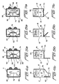
- the third bottom surface flap member 78 will be the first bottom surface flap member to be folded upwardly and inwardly, through means of an angular displacement of 90° with respect to the seventh horizontally oriented score line 80, such that the third bottom surface flap member 78 will be moved from a substantially vertical orientation to a substantially horizontal orientation as can be appreciated from Figures 4a and 4b.
- the second and fourth bottom surface flap members 70,90 are simultaneously folded upwardly and inwardly, through means of angular displacements of 90° with respect to the sixth and eighth horizontally oriented score lines 72,92, such that the second and fourth bottom surface flap members 70,90 will be moved from their substantially vertical orientations to substantially horizontal orientations.
- the trapezoidal sections 74,94 of the second and fourth bottom surface flap members 70,90 will be disposed beneath the pair of outwardly projecting, laterally spaced flap sections 86,88 of the third bottom surface flap member 78 so as to effectively retain the third bottom surface flap member 78 at its horizontal orientation when the tote container is disposed in its assembled condition.
- the first bottom surface flap member 62 is folded upwardly and inwardly, through means of three stepwise angular displacements of 45° each, with respect to the fifth horizontally oriented score line 64 such that during the first one of the 45° stepwise angular displacements or movements, the first bottom surface flap member 62 will be moved from its substantially vertical orientation to an angled orientation, as illustrated within Figures 6a and 6b, whereby the substantially trapezoidal section 66 of the first bottom surface flap member 62 begins to cover or overlap the second and fourth bottom surface flap members 70,90.
- first bottom surface flap member 62 As the first bottom surface flap member 62 is subsequently folded further upwardly and inwardly, through means of the second one of the 45° stepwise angular displacements or movements, as illustrated within Figures 7a and 7b, the first bottom surface flap member 62 will be moved from its angled orientation to a substantially horizontal orientation whereby the substantially trapezoidal section 66 of the first bottom surface flap member 62 will now fully or completely cover or overlap the substantially rectangular portions 76,96 of the second and fourth bottom surface flap members 70,90.
- the substantially rectangular portion 68 of the first bottom surface flap member 62 overlaps the substantially rectangular section 82 of the third bottom surface flap member 78.
- the width of the cutout section 84 of the third bottom surface flap member 78 is slightly larger than the width dimension of the substantially rectangular portion 68 of the first bottom surface flap member 62, and still further, that there is a space 100 defined between the inner edge regions of the substantially rectangular portions 76,96 of the second and fourth bottom surface flap members 70, 90 and the inner edge portion 98 of the third bottom surface flap member 78.
- the first bottom surface flap member 62 when the first bottom surface flap member 62 is subsequently folded upwardly and inwardly still further with respect to the fifth horizontally oriented score line 64, through means of the third one of the 45° stepwise angular displacements or movements, the first bottom surface flap member 62 will be moved from its horizontal orientation to a substantially angled orientation internally within the tote container.
- the substantially rectangular portion 68 of the first bottom surface flap member 62 will engage and be forcefully impressed into engagement with the substantially rectangular section 82 of the third bottom surface flap member 78 so as to effectively begin to force the third bottom surface flap member 78 upwardly and inwardly into the interior portion of the tote container and away from the second and fourth bottom surface flap members 70,90.
- This upward and inward movement of the third bottom surface flap member 78 continues until the third bottom surface flap member 78 is moved sufficiently away from the second and fourth bottom surface flap members 70,90 so as to effectively permit the substantially rectangular portion 68 of the first bottom surface flap member 62 to be disposed above the inner edge portion 98 of the third bottom surface flap member 78.
- the third bottom surface flap member 78 will spring or snap back to its unbiased horizontal orientation as a result of the inherent resiliency characteristic of the thermoplastic material from which the tote container blank 10 is fabricated as well as the inherent resiliency as effectively determined by means of the seventh horizontally oriented score line 80.
- Figures 3a-3e a single tote container workpiece 11, as has been illustrated and detailed within Figure 2, is disclosed or illustrated within Figure 3a as being in its flattened state, and a plurality or serial array of such tote container workpieces 11, as disposed in their flattened states, are disclosed within Figure 3b so as to effectively simulate a supply of such tote container workpieces 11 as they are disposed or contained within a tote container workpiece magazine or hopper 112 as is more particularly illustrated or disclosed within Figures 8-10.
- a vacuum suction cup assembly comprising a plurality of vacuum suction cup implements 114, is operatively associated with the downstream end of the tote container workpiece magazine or hopper 112 so as to effectively withdraw or remove the leading one of the tote container workpieces 11 from the forward or open end of the tote container workpiece magazine or hopper 112 as the vacuum suction cup assembly is moved in the direction denoted by means of the arrow DS.
- a dual roller mechanism 116 is also operatively associated with, or disposed within the vicinity of, the forward or open end of the tote container workpiece magazine or hopper 112.
- the vacuum suction cup implements 114 effectively withdraw or remove the leading one of the tote container workpieces 11 from the forward or open end of the tote container workpiece magazine or hopper 112
- the tote container workpiece 11 will effectively be opened from its flattened state to its expanded state, as a result of the tote container workpiece 11 encountering the dual roller mechanism 116 as disclosed within Figures 3c-3d, in preparation for the transformation of the tote container workpiece 11 into the desired finalized assembled or erected tote container.
- a plurality of tote container workpieces 11 are disposed within the tote container workpiece magazine or hopper 112 so as to be arranged within a serial array.
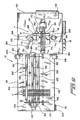
- the tote container workpiece magazine or hopper 112 is disposed within a housing 118, and the magazine or hopper framework or housing 118 is, in turn, disposed upon a machine or system framework or housing 120.
- the machine or system framework or housing 120 is mounted upon a plurality of support legs 122, and each support leg 122 has an leveling pad 124 adjustably mounted within the lowermost end portion thereof whereby not only can the machine or system framework or housing 120 be appropriately leveled, but in addition, the elevational disposition of the machine or system framework or housing 120 can be adjusted or altered as may be necessary.
- each one of the tote container workpieces 11 must be disposed in the positional orientation as disclosed within Figures 2 and 3a, that is, with the bottom surface flap members 62,70,78,90 extending vertically downwardly.
- each one of the tote container workpieces 11 is disposed within the tote container workpiece magazine or hopper 112 in a predetermined front-to-back orientation such that when each one of the tote container workpieces 11 is in fact opened from its substantially flattened state to its expanded state as disclosed, for example, within Figures 3c-3d, each tote container workpiece 11 will be positioned as disclosed within Figures 3e,4b, and 8 so as to enable the bottom surface flap members 62,70,78,90 to in fact be folded with respect to each other in accordance with the particularly unique sequence as has been previously described in connection with the disclosures of Figures 4a-7b.
- slot 126 is effectively disposed at a rightward, off-center position with respect to the lateral extent or width dimension of each tote container workpiece 11, and still further, a tote container workpiece orientation bar 128 is fixedly mounted within the tote container workpiece magazine or hopper 112 at a similar, rightward, off-center position as can best be seen in Figures 8-10.
- the tote container workpieces 11 when the plurality of tote container workpieces 11 are disposed within the tote container workpiece magazine or hopper 112 in accordance with the afore noted predetermined orientation wherein the bottom surface flap members 62,70,78,90 extend vertically downwardly, the tote container workpieces 11 will also necessarily have a predetermined front-to-back orientation, so as not to be loaded into the tote container workpiece magazine or hopper 112 in a reversed or backwards mode, as a result of the proper positional alignment defined between the slot 126 of each tote container workpiece 11 and the tote container workpiece orientation bar 128.
- tote container workpiece orientation bar 128 within the tote container workpiece magazine or hopper 112, and its interaction with the plurality of tote container workpieces 11 through means of the slot structure 126, likewise prevents the tote container workpieces 11 from moving laterally or transversely within the tote container workpiece magazine or hopper 112.
- a pair of laterally spaced conveyor drive chain mechanisms 130,130 are disposed within the bottom region of the tote container workpiece magazine or hopper 112, and it is noted that the pair of laterally spaced conveyor drive chain mechanisms 130,130 are routed around a pair of forwardly disposed powered pulleys 132,132, and a pair of rearwardly disposed idler pulleys 134,134.
- the powered pulleys 132,132 are operatively interconnected together by means of a transversely extending axle 136, and the powered pulleys 132,132 are adapted to be incrementally or indexably moved by means of a pneumatically-powered indexable or ratcheting clutch-type piston-cylinder mechanism 138 which is operatively connected to the right side powered pulley 132 by means of a suitable crank lever 140 as disclosed in Figure 8.
- a pneumatically-powered indexable or ratcheting clutch-type piston-cylinder mechanism 138 which is operatively connected to the right side powered pulley 132 by means of a suitable crank lever 140 as disclosed in Figure 8.
- the lower or bottom edge portions of, for example, the bottom surface flap members 62 and 90 are disposed atop the drive chain mechanisms 130,130. Accordingly, as the drive chain mechanisms 130,130 are indexably advanced, the serial array of tote container workpieces 11 will likewise be advanced within and through the tote container workpiece magazine or hopper 112.
- a vertically oriented pusher-plate mechanism 142 is disposed internally within the tote container workpiece magazine or hopper 112 so as to be engageable with the rear surface portion of the rearwardmost one of the plurality of serially arrayed tote container workpieces 11.
- the pusher-plate mechanism 142 is mounted upon a slide mechanism 144, and the slide mechanism 144 is slidably mounted upon a track member 146 which is effectively defined within the upper surface portion a pneumatically powered rodless cylinder mechanism 148.
- Actuation of the pneumatically powered rod-less cylinder mechanism 148, as well as the actuation of the piston-cylinder mechanism 138, is suitably controlled by means of a programmable logic controller (PLC) 150 which is mounted upon the downstream end of the machine or system framework or housing 120, and in this manner, the movements of the drive chain mechanisms 130,130, in conjunction with the movements of the pusher-plate mechanism 142, can be appropriately coordinated.
- PLC programmable logic controller
- valve mechanism 151 is operatively associated with the pneumatically powered rodless cylinder mechanism 148 so as to effectively relieve the internal pneumatic pressure whereby the slide mechanism 144, and the pusher-plate mechanism 142 mounted thereon, can be manually moved to the rear or back end of the tote container workpiece magazine or hopper 112 in preparation for the loading of a new batch of tote container workpieces 11 therewithin.
- a hold-down bar 152 is disposed immediately above the upper edge portions of the plurality of tote container workpieces 11.
- the hold-down bar 152 is adapted to be pivotally movable between a first operative position, as illustrated within Figures 8-10, whereby the hold-down bar 152 is effectively engaged with, or disposed immediately above, the plurality of tote container workpieces 11 disposed within the tote container workpiece magazine or hopper 112, and a second inoperative position, such as, for example, 180° from the first illustrated operative position, so as to effectively permit new tote container workpieces 11 to be loaded into the tote container workpiece magazine or hopper 112.
- the pivotal movement of the hold-down bar 152 is achieved by means of a pair of pneumatically-controlled piston-cylinder mechanisms 154, only one of which is illustrated within Figure 10.
- the piston-cylinder mechanisms 154 are respectively operatively connected to the hold-down bar 152 by means of a pair of longitudinally spaced actuator arms 156,156 and linkage mechanisms 158, only one of which is likewise disclosed within Figure 10, and the pneumatic power for the pair of piston-cylinder mechanisms 154 may be controlled by means of a suitable valve mechanism 160, similar to valve mechanism 151, as illustrated within Figures 8 and 9.
- the structural combination comprising the drive-chain mechanisms 130,130, the pusher-plate mechanism 142, and the hold-down bar 152, serves to properly confine and move each one of the plurality of tote container workpieces 11 within and through the tote container workpiece magazine or hopper 112 in a substantially vertical orientation such that each leading one of the tote container workpieces 11 can be serially presented to, and properly grasped by, the plurality of vacuum suction cup implements 114.
- a pair of vertically spaced photodetector systems are disposed at the downstream or exit end of the tote container workpiece magazine or hopper 112. More particularly, as can best be seen in Figure 10, a first upper phototransmitter 162 is provided for transmitting a first beam of light 163 across the conveyance path of the tote container workpieces 11, and a first upper photoreceiver 164 is provided for receiving such first beam of light 163.
- a second lower phototransmitter 166 is likewise provided for transmitting a second beam of light 167 across the conveyance path of the tote container workpieces 11, and a second lower photoreceiver 168 is provided for receiving such second beam of light 167.
- the first upper phototransmitter 162, first beam of light 163, and first upper photoreceiver 164 are operatively connected to the rodless cylinder mechanism 148 through means of the programmable logic controller (PLC) 150, while the second lower phototransmitter 166, second beam of light 167, and second lower photoreceiver 168 are likewise operatively connected to the piston-cylinder mechanism 138 through means of the programmable logic controller (PLC) 150.
- PLC programmable logic controller
- first and second phototransmitters 162,166, and the first and second photoreceivers 164,168 are all disposed within the same vertical plane which extend transversely across the downstream or exit end of the tote container workpiece magazine or hopper 112.
- first and second light beams 163,167 are substantially simultaneously interrupted by means of the leading one of the tote container workpieces 11, whereby appropriate signals to such an effect will be transmitted to the programmable logic controller (PLC) 150, then it is known that the leading one of the tote container workpieces 11 is in fact properly disposed within a vertical plane.
- PLC programmable logic controller
- the programmable logic controller (PLC) 150 can appropriately activate the indexable piston-cylinder mechanism 138 for the drive-chain mechanisms 130, 130, or activate the rodless cylinder mechanism 148 for the pusher-plate mechanism 142, as is necessary, so as to effectively align the upper and lower end portions of the tote container workpiece 11 with respect to each other within a true vertical plane.
- vacuum suction cup implements 114 actually comprise, for example, four vacuum suction cup implements which are arranged within a substantially rectangular array as can best be appreciated from Figure 10.
- the vacuum suction cup implements 114 are mounted upon the upper end portion of an upstanding plate or arm 170, and the lower end portion of the upstanding plate or arm 170 is fixedly mounted upon a slide mechanism 172.
- the slide mechanism 172 is similar to the slide mechanism 144 and is accordingly slidably mounted upon a track member 174 which is effectively defined within the upper surface portion a pneumatically powered rodless cylinder mechanism 176.
- the slide mechanism 172 and the pneumatically powered rodless cylinder mechanism 176 are under the control of the programmable logic controller (PLC) 150.
- PLC programmable logic controller
- the vacuum suction cup implements 114 when vacuum is supplied to the vacuum suction cup implements 114 from a suitable source of vacuum, not shown, under the influence or control of the programmable logic controller (PLC) 150, the vacuum suction cup implements 114 will cause the leading one of the tote container workpieces 11 to be attracted toward, and be adhered to, the vacuum suction cup implements 114.
- PLC programmable logic controller
- a suitable gate mechanism may be operatively associated with the downstream or exit end of the tote container workpiece magazine or hopper 112.
- the gate mechanism may alternatively comprise either a reciprocally movable mechanism or a pivotally movable mechanism which may be actuated by means of a suitable pneumatically-controlled piston-cylinder gate actuator 178, as illustrated within Figure 8, and the pneumatic piston-cylinder gate actuator 178 is adapted to be operatively connected to the programmable logic controller (PLC) 150 so as to be properly and timely controlled thereby.
- PLC programmable logic controller
- a suitably timed, sequentially conducted actuation cycle for the gate actuator 178 will comprise, for example, the movement of the gate mechanism, not shown, to a first, extended operative position wherein the gate mechanism, not shown, will be interposed between the leading one of the tote container workpieces 11 and the next succeeding one of the tote container workpieces 11 disposed within the tote container workpiece magazine or hopper 112 such that when the suction cup implements 114 are actuated, only the leading one of the tote container workpieces 11 will in fact be withdrawn or removed from the downstream or exit end of the tote container workpiece magazine or hopper 112 while the remaining ones of the tote container workpieces 11 will in tact be effectively retained within the tote container workpiece magazine or hopper 112 by means of the afore noted gate mechanism, not shown.
- the gate actuator 178 can be actuated so as to move the gate mechanism, not shown, to a second, retracted, inoperative position whereby the serial array of tote container workpieces 11, disposed within the tote container workpiece magazine or hopper 112, can be incrementally or indexably advanced so as to effectively dispose a new leading one of the tote container workpieces 11 at the downstream or exit end of the tote container workpiece magazine or hopper 112.
- the gate actuator 178 can then be accordingly actuated so as to return the gate mechanism, not shown, to its first, extended operative position so as to once again be interposed between the leading one of the tote container workpieces 11 and the next succeeding one of the tote container workpieces 11 disposed within the tote container workpiece magazine or hopper 112 in preparation for the next operative cycle.
- the vacuum suction cup implements 114 move the leading one of the tote container workpieces 11 toward the work station, as disclosed within Figures 8 and 9, at which the tote container workpiece 11 will be assembled or erected into the finalized tote container, the tote container workpiece 11 will encounter the dual-roller mechanism or assembly 116 as has been schematically illustrated within Figures 3c and 3d. More particularly, it is seen that the dual-roller mechanism or assembly 116 is disposed substantially immediately downstream of the downstream or exit end of the tote container workpiece magazine or hopper 112 and is also disposed toward one side of the flow path DS along which the leading one of the tote container workpieces 11 is moved by means of the vacuum suction cup implements 114.
- the dual-roller mechanism or assembly 116 comprises a first-stage opening roller 180 and a second-stage opening roller 182, where ⁇ n the first-stage and second-stage opening rollers 180,182 are mounted upon opposite ends of a connecting bar 184 such that the second-stage opening roller 182 is disposed closer to the vacuum suction cup implements 114 than is the first-stage opening roller 180.
- the end wall portion 14 of the tote container workpiece 11 cannot simply move past the first-stage opening roller 180 in a translational manner, but to the contrary, as the plurality of vacuum suction cup implements 114 cause the side wall portion 16 to move forwardly along the flow path DS, whereby the tote container workpiece 11 begins to open from its flattened state toward its expanded state, the end wall portion 14 of the tote container workpiece 11, momentarily restrained as a result of its encounter with the first-stage opening roller 180, will effectively be caused to slide along and past the first-stage opening roller 180 as disclosed within Figure 3c.
- first, second, and third folding mechanisms 186,188,190 which are adapted to be respectively powered or activated by means of pneumatically-controlled piston-cylinder actuators 192,194,196 under the timely and sequential control of the programmable logic controller (PLC) 150, are disposed upon the side and opposite ends of the expanded tote container workpiece 11, as can best be seen in Figure 9.
- PLC programmable logic controller
- the folding mechanisms 186,188,190 can respectively engage and fold the bottom surface flap members 78,70,90 of the tote container workpiece 11 upwardly and inwardly with respect to the bottom edge portions 80,72,92 of the side and end wall portions 16,14,18 of the tote container workpiece 11 in accordance with the folding sequence as previously disclosed and described in connection with Figures 4a-5b.
- a pair of additional folding mechanisms 198,200 which are likewise adapted to be respectively powered or activated by means of pneumatically-controlled piston-cylinder actuators 202,204 under the timely and sequential control of the programmable logic controller (PLC) 150, are effectively disposed opposite the folding mechanism 186 and its associated piston-cylinder actuator 192, as can best be seen in Figure 8.
- PLC programmable logic controller
- the folding mechanisms 198,200 can sequentially engage and fold the bottom surface flap member 62 of the tote container workpiece 11 upwardly and inwardly with respect to the bottom edge portion 64 of the side wall portion 12 of the tote container workpiece 11, as well as with respect to the previously folded bottom surface flap members 78,70,90, in the afore noted three-stage manner so as to effectively interlock the bottom surface flap member 62 with respect to the bottom surface flap member 78 in accordance with the folding sequence as previously disclosed and described in connection with Figures 6a-7b.
- the folding mechanism 195 is utilized to achieve the first stage 45° angular movement of the bottom surface flap member 62 as disclosed within Figures 6a,Sb, while the folding mechanism 200 is utilized to achieve the second and third stage 45° angular movements of the bottom surface flap member 62 as has been described in connection with Figures 7a,7b.
- the bottom surface flap members 62,70,78,90 are now all intermeshed, interengaged, and interlocked together, as has been previously disclosed and described, whereby assembly or erection of the tote container has now been completed, the assembled or erected tote container being disclosed at 205 within Figure 10.
- the erected or assembled tote container 205 must be removed from the assembly or erection workstation in order to permit the erection or assembly of a subsequent tote container.
- a pneumatically-controlled piston-cylinder mechanism 206 is operatively connected to the dual-roller mechanism 116, through means of a suitable linkage mechanism 208, so as to effectively move the dual-roller mechanism 116 from its illustrated operative position, at which the second-stage roller 182 is disposed in contact with the end wall portion 14 of the assembled or erected tote container 205, to a retracted or remotely located inoperative position, not illustrated, in accordance with timely transmitted signals from the programmable logic controller (PLC) 150.
- PLC programmable logic controller
- a pusher-plate mechanism 210 is adapted to engage the opposite end wall portion 18 of the completed tote container 205.
- the pusher-plate mechanism 210 is mounted upon a substantially L-shaped mounting bracket 212, and the mounting bracket 212 is, in turn, fixedly mounted upon the underside portion of a pneumatically-powered rodless cylinder assembly 214 through means of a slide mechanism 216.
- the rodless cylinder assembly 214 will be actuated so as to cause the operatively associated pusher-plate mechanism 210 thereof to move the completed tote container 205 to its discharged position 205' .
- control panels or the like 218,220 which may comprise a plurality of suitable control buttons, such as, for example, START, NORMAL STOP, SEQUENCE, EMERGENCY STOP, and the like.
- a new and improved apparatus or system for automatically assembling or erecting tote containers has been developed wherein a plurality of tote container workpieces are initially disposed in a flattened state and in a serial array within a magazine or hopper.
- the tote container workpieces are individually removed from the magazine or hopper in a serial manner and each one of the tote container workpieces is then automatically expanded from its flattened state to an opened or expanded state.
- each tote container is automatically assembled as a result of the flap members being engaged with each other in an intermeshed, inter-engaged, and interlocked manner so as to effectively form the bottom support surface of the tote container without the need for fixing, bonding, or otherwise permanently securing the flap members together.
- each tote container is then capable of being used, and as may be subsequently desired or required, and in view of the fact that the flap members are not fixed, bonded, or otherwise permanently secured together, the tote containers may be readily disassembled by disengaging or unlocking the flap members from or with respect to each other.
- the disassembled tote containers can be shipped to other locations at which, for example, the tote containers can be reused, or alternatively, the disassembled tote containers can effectively be recycled as a result of the thermoplastic tote containers being melted and re-fabricated when, for example, the structural integrity of the original tote containers may be compromised as a result of the original tote containers having effectively reached the ends of their service lives.
Landscapes
- Engineering & Computer Science (AREA)
- Mechanical Engineering (AREA)
- Making Paper Articles (AREA)
- Rigid Containers With Two Or More Constituent Elements (AREA)
- Cartons (AREA)
- Closing Of Containers (AREA)
- Supplying Of Containers To The Packaging Station (AREA)
Applications Claiming Priority (2)
| Application Number | Priority Date | Filing Date | Title |
|---|---|---|---|
| US703464 | 2000-10-31 | ||
| US10/703,464 US20050101465A1 (en) | 2003-11-10 | 2003-11-10 | Apparatus and method for erecting tote containers |
Publications (1)
| Publication Number | Publication Date |
|---|---|
| EP1529628A1 true EP1529628A1 (de) | 2005-05-11 |
Family
ID=34435575
Family Applications (1)
| Application Number | Title | Priority Date | Filing Date |
|---|---|---|---|
| EP04256732A Withdrawn EP1529628A1 (de) | 2003-11-10 | 2004-11-01 | Vorrichtung zum Aufrichten von Schachteln |
Country Status (6)
| Country | Link |
|---|---|
| US (2) | US20050101465A1 (de) |
| EP (1) | EP1529628A1 (de) |
| KR (1) | KR20050045829A (de) |
| CN (1) | CN100522590C (de) |
| CA (1) | CA2482468C (de) |
| TW (1) | TWI276581B (de) |
Cited By (1)
| Publication number | Priority date | Publication date | Assignee | Title |
|---|---|---|---|---|
| WO2022250483A1 (ko) * | 2021-05-28 | 2022-12-01 | 이요셉 | 재활용 골판지 |
Families Citing this family (10)
| Publication number | Priority date | Publication date | Assignee | Title |
|---|---|---|---|---|
| US20060185931A1 (en) * | 2005-02-04 | 2006-08-24 | Kawar Maher S | Acoustic noise reduction apparatus for personal computers and electronics |
| EP3318399A1 (de) * | 2016-11-04 | 2018-05-09 | Tetra Laval Holdings & Finance S.A. | Faltvorrichtung, system und verfahren zum partiellen falten einer verpackung aus einem zuschnitt |
| CN106395004A (zh) * | 2016-11-28 | 2017-02-15 | 张家港爱铝铝箔科技有限公司 | 用于纸盒的输送装置及装盒机 |
| AU2019253436B2 (en) * | 2018-04-09 | 2022-03-24 | Graphic Packaging International, Llc | Carton with liner |
| CN109986833B (zh) * | 2019-04-30 | 2023-12-15 | 宜昌昌盛包装有限公司 | 一种瓦楞纸箱生产过程中的折叠整理装置 |
| FR3101858B1 (fr) * | 2019-10-10 | 2021-10-29 | Sidel Packing Solutions | Dispositif et procédé de formage de conteneur par pliage |
| CN110901154A (zh) * | 2019-11-27 | 2020-03-24 | 肖志坚 | 一种包装盒加工用折边装置 |
| CN114274590A (zh) * | 2021-12-22 | 2022-04-05 | 深圳市智立方自动化设备股份有限公司 | 一种异型纸盒上折弯机构 |
| CN115384876A (zh) * | 2022-08-22 | 2022-11-25 | 山东艾琳智能科技有限公司 | 一种养老陪护机器人的包装盒自动拆封箱装置 |
| CN119189418B (zh) * | 2024-08-15 | 2025-10-28 | 广东东方精工科技股份有限公司 | 一种纸板开槽装置 |
Citations (4)
| Publication number | Priority date | Publication date | Assignee | Title |
|---|---|---|---|---|
| US5120293A (en) * | 1990-09-14 | 1992-06-09 | Bishopbarn Limited | Erection mechanism for packing cases |
| FR2697497A1 (fr) * | 1992-10-29 | 1994-05-06 | Lanchais Martial | Procédé et machine de formage d'un fond de boîte "coup de poing". |
| EP1310354A1 (de) * | 2001-11-13 | 2003-05-14 | TMG Impianti S.r.l. | Maschine zum Formen von Kartons |
| EP1332973A1 (de) * | 2002-01-25 | 2003-08-06 | Kwan Wing Kwong | Universelle Geschenkschachtel |
Family Cites Families (30)
| Publication number | Priority date | Publication date | Assignee | Title |
|---|---|---|---|---|
| US3343466A (en) * | 1965-03-16 | 1967-09-26 | Olinkraft Inc | Carton erector apparatus and process |
| SE424165B (sv) * | 1978-09-15 | 1982-07-05 | Sundpacma Ab | Anordning vid maskin for uppresning och forslutning av slitslador |
| US4516381A (en) * | 1981-04-02 | 1985-05-14 | Ace Pak Company Incorporated | Automatic carton packing machine |
| US4509312A (en) * | 1981-04-02 | 1985-04-09 | Ace Pak Company Incorporated | Automatic carton packing machine |
| US4448013A (en) * | 1981-04-02 | 1984-05-15 | Ace Pak Company Incorporated | Automatic carton packing machine |
| US4545175A (en) * | 1982-06-15 | 1985-10-08 | Marq Packaging Systems, Inc. | Programmable random size case sealing machine |
| US4516210A (en) * | 1983-04-18 | 1985-05-07 | Marq Packaging Systems, Inc. | Programmable tray forming machine |
| US4632666A (en) * | 1984-03-15 | 1986-12-30 | Durable Packaging | Carton errector apparatus |
| US4584818A (en) * | 1985-08-20 | 1986-04-29 | Frito-Lay, Inc. | Apparatus for automatically closing L-slide lock cartons |
| US4627217A (en) * | 1985-08-20 | 1986-12-09 | Frito-Lay, Inc. | Apparatus for automatically closing L-slide lock cases |
| US4656810A (en) * | 1986-07-01 | 1987-04-14 | Frito-Lay, Inc. | Apparatus for automatically locking L-slide lock cartons |
| DE3812749A1 (de) * | 1988-04-16 | 1989-10-26 | Winkler Duennebier Kg Masch | Verfahren und vorrichtung zum oeffnen der verschlussklappen eines kartons |
| JPH0739634Y2 (ja) * | 1988-12-28 | 1995-09-13 | 四国化工機株式会社 | 容器底部成形用マンドレルへの容器ブランク供給装置 |
| US5102382A (en) * | 1989-08-25 | 1992-04-07 | Recot, Inc. | Method and apparatus for closing bottom end flaps of a carton |
| GB8924078D0 (en) * | 1989-10-26 | 1989-12-13 | Tetra Pak Ab | Continuous to intermittent feeding interface |
| US5234398A (en) * | 1990-06-02 | 1993-08-10 | Elopak Systems Ag | Method and apparatus for folding end closure panels |
| US5415613A (en) * | 1992-12-22 | 1995-05-16 | Mcgrath; Stephen E. | Apparatus for making a locking join for boxes |
| US5352178A (en) * | 1993-02-12 | 1994-10-04 | Douglas Machine Limited Liability Company | Collapsed, tubular carton erecting apparatus |
| US5454776A (en) * | 1993-10-14 | 1995-10-03 | Durable Packaging Corporation | Carton bottom folder and sealer |
| US5514068A (en) * | 1993-11-16 | 1996-05-07 | The Mead Corporation | Machine and method for erecting basket style cartons |
| IT1274052B (it) * | 1994-10-07 | 1997-07-14 | Azionaria Costruzioni Automati | Metodo per l'espansione di astucci e per la loro alimentazione ad una linea di riempimento. |
| GB9421188D0 (en) * | 1994-10-20 | 1994-12-07 | Riverwood Int Ltd | Paperboard interlock arrangement |
| DE4439198A1 (de) * | 1994-11-06 | 1996-05-09 | Klett Alfred | Vorrichtung zur Bearbeitung eines entlang eines Förderwegs mit vorgegebener Fördergeschwindigkeit geförderten Zuschnitts |
| US5876319A (en) * | 1995-06-07 | 1999-03-02 | Delaware Capital Formation, Inc. | Container forming method and apparatus |
| ATE246594T1 (de) * | 1997-01-23 | 2003-08-15 | Sig Pack Systems Ag | Flexible anlage zum aufrichten von kartonzuschnitten |
| US5826408A (en) * | 1997-05-08 | 1998-10-27 | Riverwood International Corporation | Rotary flap tucker for a cartoning machine |
| US6599225B2 (en) * | 1998-10-27 | 2003-07-29 | International Paper Company | Method of closing the bottom of a container |
| US6309335B1 (en) * | 1999-11-10 | 2001-10-30 | Delaware Capital Formation | Vertically displaced hopper for bliss machines |
| ITBO20010057A1 (it) * | 2001-02-05 | 2002-08-05 | Baumer Srl | Metodo e sistema per chiudere i lembi delle testate di un imballo a manicotto |
| US6764436B1 (en) * | 2003-01-11 | 2004-07-20 | Mark Stanley Mazurek | Method and apparatus for squaring cases |
-
2003
- 2003-11-10 US US10/703,464 patent/US20050101465A1/en not_active Abandoned
-
2004
- 2004-09-23 CA CA002482468A patent/CA2482468C/en not_active Expired - Fee Related
- 2004-11-01 EP EP04256732A patent/EP1529628A1/de not_active Withdrawn
- 2004-11-02 KR KR1020040088286A patent/KR20050045829A/ko not_active Withdrawn
- 2004-11-05 CN CNB2004100886112A patent/CN100522590C/zh not_active Expired - Fee Related
- 2004-11-10 TW TW093134231A patent/TWI276581B/zh not_active IP Right Cessation
-
2005
- 2005-04-11 US US11/102,859 patent/US7647751B2/en not_active Expired - Fee Related
Patent Citations (4)
| Publication number | Priority date | Publication date | Assignee | Title |
|---|---|---|---|---|
| US5120293A (en) * | 1990-09-14 | 1992-06-09 | Bishopbarn Limited | Erection mechanism for packing cases |
| FR2697497A1 (fr) * | 1992-10-29 | 1994-05-06 | Lanchais Martial | Procédé et machine de formage d'un fond de boîte "coup de poing". |
| EP1310354A1 (de) * | 2001-11-13 | 2003-05-14 | TMG Impianti S.r.l. | Maschine zum Formen von Kartons |
| EP1332973A1 (de) * | 2002-01-25 | 2003-08-06 | Kwan Wing Kwong | Universelle Geschenkschachtel |
Cited By (1)
| Publication number | Priority date | Publication date | Assignee | Title |
|---|---|---|---|---|
| WO2022250483A1 (ko) * | 2021-05-28 | 2022-12-01 | 이요셉 | 재활용 골판지 |
Also Published As
| Publication number | Publication date |
|---|---|
| CA2482468A1 (en) | 2005-05-10 |
| TWI276581B (en) | 2007-03-21 |
| US20050176567A1 (en) | 2005-08-11 |
| TW200524791A (en) | 2005-08-01 |
| US20050101465A1 (en) | 2005-05-12 |
| CN1683153A (zh) | 2005-10-19 |
| KR20050045829A (ko) | 2005-05-17 |
| US7647751B2 (en) | 2010-01-19 |
| CA2482468C (en) | 2008-12-09 |
| CN100522590C (zh) | 2009-08-05 |
Similar Documents
| Publication | Publication Date | Title |
|---|---|---|
| US11897222B2 (en) | Method and apparatus for erecting cartons | |
| CA3079176C (en) | Method and apparatus for erecting cartons and for order fulfilment and packing | |
| US8671654B2 (en) | Method and system for forming containers with corrugated material | |
| US7647751B2 (en) | Apparatus and method for erecting tote containers | |
| CA2176759C (en) | Means for erecting cartons having collapsible bottoms | |
| US8024910B2 (en) | Methods and apparatus for forming a container | |
| US20210229390A1 (en) | Methods and machine for forming a shipping container with an article retaining web | |
| US20150072847A1 (en) | Methods and machine for forming a shipping and display container from a blank assembly using a pre-fold mandrel section | |
| US11718428B2 (en) | Methods and machine for packaging primary containers in secondary containers and a shipping tray | |
| AU604264B2 (en) | Carton forming and packaging machine | |
| US6306070B1 (en) | Apparatus for erecting and sealing flat containers and associated methods | |
| CN114466796B (zh) | 用于二级包装的包装设备 | |
| CA2687847A1 (en) | Method and apparatus for forming containers with corrugated material | |
| US20260102984A1 (en) | Method and apparatus for erecting cartons and for order fulfilment and packing | |
| JPH09240621A (ja) | カートンの集積装置 | |
| JPH09240623A (ja) | カートンの組立装置 | |
| JPH068915A (ja) | 袋詰装置及び袋詰方法等 | |
| CA2863063A1 (en) | Methods and machine for forming a shipping and display container from a blank assembly using a pre-fold mandrel section |
Legal Events
| Date | Code | Title | Description |
|---|---|---|---|
| PUAI | Public reference made under article 153(3) epc to a published international application that has entered the european phase |
Free format text: ORIGINAL CODE: 0009012 |
|
| AK | Designated contracting states |
Kind code of ref document: A1 Designated state(s): AT BE BG CH CY CZ DE DK EE ES FI FR GB GR HU IE IS IT LI LU MC NL PL PT RO SE SI SK TR |
|
| AX | Request for extension of the european patent |
Extension state: AL HR LT LV MK YU |
|
| 17P | Request for examination filed |
Effective date: 20051107 |
|
| AKX | Designation fees paid |
Designated state(s): AT BE BG CH CY CZ DE DK EE ES FI FR GB GR HU IE IS IT LI LU MC NL PL PT RO SE SI SK TR |
|
| STAA | Information on the status of an ep patent application or granted ep patent |
Free format text: STATUS: THE APPLICATION HAS BEEN WITHDRAWN |
|
| 18W | Application withdrawn |
Effective date: 20090114 |