EP1529474A1 - Appareil electromenager comportant un boitier renfermant un moteur reposant sur le boitier par l'intermediaire d'elements amortisseur - Google Patents
Appareil electromenager comportant un boitier renfermant un moteur reposant sur le boitier par l'intermediaire d'elements amortisseur Download PDFInfo
- Publication number
- EP1529474A1 EP1529474A1 EP04356164A EP04356164A EP1529474A1 EP 1529474 A1 EP1529474 A1 EP 1529474A1 EP 04356164 A EP04356164 A EP 04356164A EP 04356164 A EP04356164 A EP 04356164A EP 1529474 A1 EP1529474 A1 EP 1529474A1
- Authority
- EP
- European Patent Office
- Prior art keywords
- housing
- motor
- damping elements
- domestic appliance
- appliance according
- Prior art date
- Legal status (The legal status is an assumption and is not a legal conclusion. Google has not performed a legal analysis and makes no representation as to the accuracy of the status listed.)
- Granted
Links
Images
Classifications
-
- A—HUMAN NECESSITIES
- A47—FURNITURE; DOMESTIC ARTICLES OR APPLIANCES; COFFEE MILLS; SPICE MILLS; SUCTION CLEANERS IN GENERAL
- A47J—KITCHEN EQUIPMENT; COFFEE MILLS; SPICE MILLS; APPARATUS FOR MAKING BEVERAGES
- A47J43/00—Implements for preparing or holding food, not provided for in other groups of this subclass
- A47J43/04—Machines for domestic use not covered elsewhere, e.g. for grinding, mixing, stirring, kneading, emulsifying, whipping or beating foodstuffs, e.g. power-driven
- A47J43/07—Parts or details, e.g. mixing tools, whipping tools
- A47J43/08—Driving mechanisms
- A47J43/082—Driving mechanisms for machines with tools driven from the upper side
Definitions
- the present invention relates to the general technical field of apparatus household appliances including food preparation.
- the present invention relates more particularly to an apparatus comprising a housing enclosing a motor resting on the housing via damping elements arranged at the longitudinal ends of the engine.
- a household electrical appliance comprising a housing incorporating a motor whose output shaft opens at a longitudinal end of the housing that can be coupled to a mixing stand.
- the engine is mounted on damping elements constituted by flexible bearings interposing between the ends longitudinal motor and housing body.
- damping elements constituted by flexible bearings interposing between the ends longitudinal motor and housing body.
- damping elements have the disadvantage of being simply placed at each end of the engine, without being held on these last, which forces to mount the damping elements during the engine mounting step on the body of the housing. It follows a lack of flexibility in the fitting logistics of damping elements and a complication of mounting the device.
- the following invention aims to overcome these disadvantages by proposing a housing domestic appliance having a motor with damping elements which remain attached to the engine once mounted on the latter.
- a household appliance comprising a housing enclosing a motor, the engine resting on the housing via damping elements arranged at the longitudinal ends of the motor, characterized in that the end damper elements are interconnected by at least one elastic connecting arm so as to form a single piece interface, the connecting arm ensuring the maintenance of the damping elements on the longitudinal ends of the engine.
- Such a characteristic allows the mounting of the damping elements on the motor in a phase of preliminary assembly and independent of the phase of mounting the motor in the housing, which has the advantage of simplifying the mounting of the device, allowing in particular the delivery of the engine with the pre-assembled damping elements.
- Such a characteristic also presents the advantage of reducing the number of referenced parts for the manufacture of the device.
- the damping elements end are interconnected by two resilient connecting arms arranged symmetrically with respect to the longitudinal axis of the engine.
- Such a characteristic has the advantage of ensuring excellent maintenance damping elements on the motor, the elastic connecting arms also helping to protect the engine sideways from impact, example during his transport.
- the damping elements and the Elastic connecting arms form a monobloc interface piece.
- the interface piece is obtained by molding.
- the damping elements end-pieces have housings in which are inserted positioning pins carried by the motor.
- one of the damping elements end has a central opening for the passage of the shaft of the engine.
- At least one of the elements end damper has bosses cooperating with legs housing to achieve the correct positioning of the engine.
- the housing of the apparatus is intended to be coupled to a mixing stand.
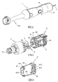
- FIGS. 1 represents a mixer comprising a housing 1 coupled to a foot 100 mixing.
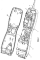
- the housing 1 comprises a body constituted by two shells 10 assembled one on the other which enclose a motor 2 and a gearbox 3, the latter being provided with a coach rotary 31 arranged next to an opening made in the end front housing 1 to be coupled to the mixing foot 100.
- the engine 2 has an output shaft 20 which is connected to the shaft of training 30 of the gearbox 3 by means of a universal joint 4, the shaft 30 supporting a fan 9 creating a flow of air ensuring the gearbox 3 and motor 2 cooling.
- the motor 2 is electrically powered by a cord 5 passing through the end rear of the housing 1, the operation of the engine 2 being controlled by a switch 6 actuated by a control button 7 disposed at the level of the central part of the housing 1.
- the motor 2 is arranged along the axis longitudinal housing 1 and is maintained through a room interface 8, on legs 11 carried by the shells 10 of the housing 1.
- the interface piece 8 is constituted by two damping elements 81 interconnected by elastic links 82, the two damping elements 81 being placed at the ends of the engine 2 and maintained on the latter by the elastic deformation of the connections 82.
- the two damping elements 81 present advantageously a rectangular general shape extending transversely to the body of the engine 2 and conforming to the shape of the ends of the engine 2.
- the damping element 81 arranged on the output shaft side of the engine 2 has in its center an opening 810 allowing the passage of the shaft 20 and is provided at its lateral ends with housings 811 in which inserted positioning pins 21 carried by the body of the engine 2.
- the damping element 81 disposed opposite the output shaft 20 of the engine has in turn a hemispherical housing 812 receiving a protruding end of the motor shaft 20, the insertion of this protuberance in the housing 812 centering the damping element 81 on the longitudinal end of the engine 2.
- This damping element 81 comprises also side bosses 813 cooperating with the legs 11 for carry out the centering of the motor 2 in the longitudinal axis of the housing 1.
- Such an interface piece has the advantage of remaining attached to the motor a once mounted on the latter, which allows its mounting in a phase prior to mounting the motor in the housing. So, the interface piece will be advantageously mounted on the engine at the place of manufacture of the engine, the interface piece then having the advantage of protecting the motor of possible shocks during transport to the assembly line of the device.
- the two elements end damper can be connected by a single link arm elastic and have, opposite the junction with the connecting arm, holes that catch on the lugs carried by the engine to ensure the maintaining the interface piece under the voltage generated by the link arm elastic.
Landscapes
- Engineering & Computer Science (AREA)
- Mechanical Engineering (AREA)
- Food Science & Technology (AREA)
- Motor Or Generator Frames (AREA)
- Vibration Prevention Devices (AREA)
- Food-Manufacturing Devices (AREA)
- Brushes (AREA)
Abstract
Description
- la figure 1 est une vue en perspective d'un appareil électroménager selon un mode particulier de réalisation de l'invention ;
- la figure 2 est une autre vue en perspective du boítier de la figure 1 avec sa coquille supérieure démontée;
- la figure 3 représente une vue en perspective des moteur et réducteur contenus dans le boítier de la figure 1 ;
- la figure 4 est une vue de détail de l'élément amortisseur supportant le moteur.
Claims (8)
- Appareil électroménager comportant un boítier (1) renfermant un moteur (2), ledit moteur (2) reposant sur ledit boítier (1) par l'intermédiaire d'éléments amortisseur (81) disposés aux extrémités longitudinales dudit moteur (2), caractérisé en ce que lesdits éléments amortisseur (81) d'extrémité sont reliés entre eux par au moins un bras de liaison (82) élastique de manière à former une seule pièce interface (8), ledit bras de liaison (82) assurant le maintien des éléments amortisseur (81) sur les extrémités longitudinales du moteur (2).
- Appareil électroménager selon la revendication 1, caractérisé en ce que lesdits éléments amortisseur (81) d'extrémité sont reliés entre eux par deux bras de liaison (82) élastiques disposés symétriquement par rapport à l'axe longitudinal du moteur (2).
- Appareil électroménager selon l'une quelconque des revendications 1 à 2, caractérisé en ce que lesdits éléments amortisseur (81) et lesdits bras de liaison (82) élastiques forment une pièce interface (8) monobloc.
- Appareil électroménager selon la revendication 3, caractérisé en ce que ladite pièce interface (8) est obtenue par moulage.
- Appareil électroménager selon l'une quelconque des revendications 1 à 4, caractérisé en ce que lesdits éléments amortisseur (81) d'extrémité comportent des logements dans lesquels viennent s'insérer des ergots de positionnement portés par le moteur (2).
- Appareil électroménager selon l'une quelconque des revendications 1 à 5, caractérisé en ce qu'au moins l'un desdits éléments amortisseur (81) d'extrémité comporte une ouverture centrale (810) pour le passage de l'arbre du moteur (2).
- Appareil électroménager selon l'une quelconque des revendications 1 à 6, caractérisé en ce qu'au moins l'un desdits éléments amortisseur (81) d'extrémité comporte des bossages (813) venant coopérer avec des pattes (11) du boítier pour réaliser le positionnement correct du moteur (2).
- Appareil électroménager selon l'une quelconque des revendications 1 à 7, caractérisé en ce que ledit boítier (1) est destiné à être accouplé à un pied de mixage (100).
Applications Claiming Priority (2)
| Application Number | Priority Date | Filing Date | Title |
|---|---|---|---|
| FR0312917A FR2861567B1 (fr) | 2003-11-04 | 2003-11-04 | Appareil electromenager comportant un boitier renfermant un moteur reposant sur le boitier par l'intermediaire d'elements amortisseur |
| FR0312917 | 2003-11-04 |
Publications (2)
| Publication Number | Publication Date |
|---|---|
| EP1529474A1 true EP1529474A1 (fr) | 2005-05-11 |
| EP1529474B1 EP1529474B1 (fr) | 2008-06-04 |
Family
ID=34429874
Family Applications (1)
| Application Number | Title | Priority Date | Filing Date |
|---|---|---|---|
| EP04356164A Expired - Lifetime EP1529474B1 (fr) | 2003-11-04 | 2004-10-08 | Appareil électroménager comportant un boitier renfermant un moteur reposant sur le boitier par l'intermédiaire d'éléments amortisseurs |
Country Status (6)
| Country | Link |
|---|---|
| EP (1) | EP1529474B1 (fr) |
| CN (1) | CN100571590C (fr) |
| AT (1) | ATE397404T1 (fr) |
| DE (1) | DE602004014225D1 (fr) |
| ES (1) | ES2308130T3 (fr) |
| FR (1) | FR2861567B1 (fr) |
Cited By (4)
| Publication number | Priority date | Publication date | Assignee | Title |
|---|---|---|---|---|
| WO2013020571A1 (fr) | 2011-08-05 | 2013-02-14 | Dkb Household Switzerland Ag | Mixeur plongeur |
| EP3593686A1 (fr) * | 2018-07-13 | 2020-01-15 | Seb S.A. | Système de ventilation d'un mixeur |
| FR3094884A1 (fr) | 2019-04-15 | 2020-10-16 | Seb S.A. | Boitier motorise d’appareil electromenager de preparation culinaire |
| RU2788622C2 (ru) * | 2018-07-13 | 2023-01-23 | Себ С.А. | Система вентиляции портативного электробытового прибора для обработки пищевых продуктов типа миксера или взбивалки |
Citations (1)
| Publication number | Priority date | Publication date | Assignee | Title |
|---|---|---|---|---|
| FR2794017A1 (fr) * | 1999-05-27 | 2000-12-01 | Moulinex Sa | Mixeur menager de type plongeant |
Family Cites Families (3)
| Publication number | Priority date | Publication date | Assignee | Title |
|---|---|---|---|---|
| CN1050592A (zh) * | 1989-09-25 | 1991-04-10 | 北京市科学技术开发交流中心 | 内减振旋转式压缩机 |
| BR9610033A (pt) * | 1995-08-15 | 1999-07-06 | Exxon Chemical Patents Inc | Amortecedor de vibraç o e/ou vulcanizado de isolamento tendo estabilidade em elevada temperatura |
| ES2190714B1 (es) * | 2000-12-05 | 2004-04-01 | Cristobal Lozano Fernandez | Boquilla de limpieza de flujo controlado. |
-
2003
- 2003-11-04 FR FR0312917A patent/FR2861567B1/fr not_active Expired - Fee Related
-
2004
- 2004-10-08 EP EP04356164A patent/EP1529474B1/fr not_active Expired - Lifetime
- 2004-10-08 AT AT04356164T patent/ATE397404T1/de not_active IP Right Cessation
- 2004-10-08 DE DE602004014225T patent/DE602004014225D1/de not_active Expired - Lifetime
- 2004-10-08 ES ES04356164T patent/ES2308130T3/es not_active Expired - Lifetime
- 2004-11-03 CN CNB2004100883612A patent/CN100571590C/zh not_active Expired - Lifetime
Patent Citations (1)
| Publication number | Priority date | Publication date | Assignee | Title |
|---|---|---|---|---|
| FR2794017A1 (fr) * | 1999-05-27 | 2000-12-01 | Moulinex Sa | Mixeur menager de type plongeant |
Cited By (8)
| Publication number | Priority date | Publication date | Assignee | Title |
|---|---|---|---|---|
| WO2013020571A1 (fr) | 2011-08-05 | 2013-02-14 | Dkb Household Switzerland Ag | Mixeur plongeur |
| EP3593686A1 (fr) * | 2018-07-13 | 2020-01-15 | Seb S.A. | Système de ventilation d'un mixeur |
| FR3083688A1 (fr) * | 2018-07-13 | 2020-01-17 | Seb S.A. | Systeme de ventilation d'un appareil electro-menager portatif de traitement de preparations alimentaires, de type mixeur / batteur |
| KR20200007749A (ko) * | 2018-07-13 | 2020-01-22 | 세브 에스.아. | 믹서/블렌더 유형의 식재료 처리용 핸디 가전기기의 환기 시스템 |
| RU2788622C2 (ru) * | 2018-07-13 | 2023-01-23 | Себ С.А. | Система вентиляции портативного электробытового прибора для обработки пищевых продуктов типа миксера или взбивалки |
| FR3094884A1 (fr) | 2019-04-15 | 2020-10-16 | Seb S.A. | Boitier motorise d’appareil electromenager de preparation culinaire |
| EP3725197A1 (fr) | 2019-04-15 | 2020-10-21 | Seb S.A. | Boitier motorise d'appareil electromenager de preparation culinaire |
| CN111820776A (zh) * | 2019-04-15 | 2020-10-27 | Seb公司 | 烹饪制备家电设备的电动盒 |
Also Published As
| Publication number | Publication date |
|---|---|
| DE602004014225D1 (de) | 2008-07-17 |
| FR2861567A1 (fr) | 2005-05-06 |
| ES2308130T3 (es) | 2008-12-01 |
| CN1613414A (zh) | 2005-05-11 |
| ATE397404T1 (de) | 2008-06-15 |
| EP1529474B1 (fr) | 2008-06-04 |
| CN100571590C (zh) | 2009-12-23 |
| FR2861567B1 (fr) | 2005-12-30 |
Similar Documents
| Publication | Publication Date | Title |
|---|---|---|
| EP0186581B1 (fr) | Motoventilateur, notamment pour véhicule automobile, fixé sur des bras supports solidaires de la carrosserie | |
| FR2837653A1 (fr) | Moteur a vibrations | |
| FR2904060B1 (fr) | Demarreur ayant un element de connexion connectant electriquement un commutateur magnetique et un moteur electrique | |
| EP1375901B1 (fr) | Procédé d'assemblage d'une pompe électrique, et amortisseur de vibrations pour une telle pompe | |
| FR2795880A1 (fr) | Alternateur pour automobile | |
| EP3544120A1 (fr) | Equipement électrique et procédé de mise à la terre pour un tel équipement | |
| EP1529474B1 (fr) | Appareil électroménager comportant un boitier renfermant un moteur reposant sur le boitier par l'intermédiaire d'éléments amortisseurs | |
| EP2042065B1 (fr) | Appareil électroménager de préparation culinaire prévu pour être tenu à la main muni d'un élément guide cordon | |
| EP0292366B1 (fr) | Plaque porte-balais notamment pour moteur électrique | |
| FR2837633A1 (fr) | Moteur de vibration du type piece de monnaie | |
| FR2772844A1 (fr) | Dispositif de canalisation d'un flux d'air, notamment pour vehicule automobile | |
| EP1529473B1 (fr) | Boîtier d'appareil électroménager de préparation culinaire prevu pour être tenu à la main selon différentes positions | |
| EP2940800B1 (fr) | Organe de connexion electrique entre deux cartes electroniques et procédé de connexion associé | |
| FR2780212A1 (fr) | Moteur electrique comprenant un agencement de liaison | |
| FR2636492A1 (fr) | Boitier pour circuits electroniques notamment pour vehicule automobile | |
| FR2707429A1 (fr) | Accessoire de raccordement. | |
| WO2020053420A1 (fr) | Machine électrique tournante munie d'un manchon de liaison intégrant un amortisseur | |
| WO1999065374A1 (fr) | Appareil electrique de cuisson a cuve amovible | |
| FR2536221A1 (fr) | Dispositif de support et de connexion d'un moteur electrique | |
| EP3520206B1 (fr) | Machine electrique tournante avec un element anti-rebouclage de flux muni de plots d'obturation | |
| FR2621750A3 (fr) | Machine electrique, en particulier moteur electrique pour essuie-glace de vehicule a moteur, a collecteur et porte-balais supporte par le carter au moyen d'elements electriques | |
| FR2528794A1 (fr) | Rotor a contre-couple pour helicopteres | |
| FR2897992A1 (fr) | Dispositif d'assemblage pour moteur electrique. | |
| FR2624715A1 (fr) | Aspirateur electrique de poussieres, notamment manuel | |
| EP3725197B1 (fr) | Boitier motorise d'appareil electromenager de preparation culinaire |
Legal Events
| Date | Code | Title | Description |
|---|---|---|---|
| PUAI | Public reference made under article 153(3) epc to a published international application that has entered the european phase |
Free format text: ORIGINAL CODE: 0009012 |
|
| AK | Designated contracting states |
Kind code of ref document: A1 Designated state(s): AT BE BG CH CY CZ DE DK EE ES FI FR GB GR HU IE IT LI LU MC NL PL PT RO SE SI SK TR |
|
| AX | Request for extension of the european patent |
Extension state: AL HR LT LV MK |
|
| 17P | Request for examination filed |
Effective date: 20051108 |
|
| AKX | Designation fees paid |
Designated state(s): AT BE BG CH CY CZ DE DK EE ES FI FR GB GR HU IE IT LI LU MC NL PL PT RO SE SI SK TR |
|
| GRAP | Despatch of communication of intention to grant a patent |
Free format text: ORIGINAL CODE: EPIDOSNIGR1 |
|
| GRAS | Grant fee paid |
Free format text: ORIGINAL CODE: EPIDOSNIGR3 |
|
| GRAA | (expected) grant |
Free format text: ORIGINAL CODE: 0009210 |
|
| AK | Designated contracting states |
Kind code of ref document: B1 Designated state(s): AT BE BG CH CY CZ DE DK EE ES FI FR GB GR HU IE IT LI LU MC NL PL PT RO SE SI SK TR |
|
| REG | Reference to a national code |
Ref country code: GB Ref legal event code: FG4D Free format text: NOT ENGLISH |
|
| REG | Reference to a national code |
Ref country code: CH Ref legal event code: EP |
|
| REF | Corresponds to: |
Ref document number: 602004014225 Country of ref document: DE Date of ref document: 20080717 Kind code of ref document: P |
|
| REG | Reference to a national code |
Ref country code: IE Ref legal event code: FG4D Free format text: LANGUAGE OF EP DOCUMENT: FRENCH |
|
| PG25 | Lapsed in a contracting state [announced via postgrant information from national office to epo] |
Ref country code: SI Free format text: LAPSE BECAUSE OF FAILURE TO SUBMIT A TRANSLATION OF THE DESCRIPTION OR TO PAY THE FEE WITHIN THE PRESCRIBED TIME-LIMIT Effective date: 20080604 Ref country code: FI Free format text: LAPSE BECAUSE OF FAILURE TO SUBMIT A TRANSLATION OF THE DESCRIPTION OR TO PAY THE FEE WITHIN THE PRESCRIBED TIME-LIMIT Effective date: 20080604 |
|
| PG25 | Lapsed in a contracting state [announced via postgrant information from national office to epo] |
Ref country code: PL Free format text: LAPSE BECAUSE OF FAILURE TO SUBMIT A TRANSLATION OF THE DESCRIPTION OR TO PAY THE FEE WITHIN THE PRESCRIBED TIME-LIMIT Effective date: 20080604 Ref country code: NL Free format text: LAPSE BECAUSE OF FAILURE TO SUBMIT A TRANSLATION OF THE DESCRIPTION OR TO PAY THE FEE WITHIN THE PRESCRIBED TIME-LIMIT Effective date: 20080604 Ref country code: AT Free format text: LAPSE BECAUSE OF FAILURE TO SUBMIT A TRANSLATION OF THE DESCRIPTION OR TO PAY THE FEE WITHIN THE PRESCRIBED TIME-LIMIT Effective date: 20080604 |
|
| NLV1 | Nl: lapsed or annulled due to failure to fulfill the requirements of art. 29p and 29m of the patents act | ||
| REG | Reference to a national code |
Ref country code: ES Ref legal event code: FG2A Ref document number: 2308130 Country of ref document: ES Kind code of ref document: T3 |
|
| REG | Reference to a national code |
Ref country code: IE Ref legal event code: FD4D |
|
| PG25 | Lapsed in a contracting state [announced via postgrant information from national office to epo] |
Ref country code: SE Free format text: LAPSE BECAUSE OF FAILURE TO SUBMIT A TRANSLATION OF THE DESCRIPTION OR TO PAY THE FEE WITHIN THE PRESCRIBED TIME-LIMIT Effective date: 20080904 Ref country code: PT Free format text: LAPSE BECAUSE OF FAILURE TO SUBMIT A TRANSLATION OF THE DESCRIPTION OR TO PAY THE FEE WITHIN THE PRESCRIBED TIME-LIMIT Effective date: 20081104 Ref country code: CZ Free format text: LAPSE BECAUSE OF FAILURE TO SUBMIT A TRANSLATION OF THE DESCRIPTION OR TO PAY THE FEE WITHIN THE PRESCRIBED TIME-LIMIT Effective date: 20080604 Ref country code: IE Free format text: LAPSE BECAUSE OF FAILURE TO SUBMIT A TRANSLATION OF THE DESCRIPTION OR TO PAY THE FEE WITHIN THE PRESCRIBED TIME-LIMIT Effective date: 20080604 |
|
| PG25 | Lapsed in a contracting state [announced via postgrant information from national office to epo] |
Ref country code: SK Free format text: LAPSE BECAUSE OF FAILURE TO SUBMIT A TRANSLATION OF THE DESCRIPTION OR TO PAY THE FEE WITHIN THE PRESCRIBED TIME-LIMIT Effective date: 20080604 Ref country code: RO Free format text: LAPSE BECAUSE OF FAILURE TO SUBMIT A TRANSLATION OF THE DESCRIPTION OR TO PAY THE FEE WITHIN THE PRESCRIBED TIME-LIMIT Effective date: 20080604 |
|
| PLBE | No opposition filed within time limit |
Free format text: ORIGINAL CODE: 0009261 |
|
| STAA | Information on the status of an ep patent application or granted ep patent |
Free format text: STATUS: NO OPPOSITION FILED WITHIN TIME LIMIT |
|
| BERE | Be: lapsed |
Owner name: SEB S.A. Effective date: 20081031 |
|
| PG25 | Lapsed in a contracting state [announced via postgrant information from national office to epo] |
Ref country code: DK Free format text: LAPSE BECAUSE OF FAILURE TO SUBMIT A TRANSLATION OF THE DESCRIPTION OR TO PAY THE FEE WITHIN THE PRESCRIBED TIME-LIMIT Effective date: 20080604 Ref country code: EE Free format text: LAPSE BECAUSE OF FAILURE TO SUBMIT A TRANSLATION OF THE DESCRIPTION OR TO PAY THE FEE WITHIN THE PRESCRIBED TIME-LIMIT Effective date: 20080604 Ref country code: BG Free format text: LAPSE BECAUSE OF FAILURE TO SUBMIT A TRANSLATION OF THE DESCRIPTION OR TO PAY THE FEE WITHIN THE PRESCRIBED TIME-LIMIT Effective date: 20080904 |
|
| 26N | No opposition filed |
Effective date: 20090305 |
|
| PG25 | Lapsed in a contracting state [announced via postgrant information from national office to epo] |
Ref country code: MC Free format text: LAPSE BECAUSE OF NON-PAYMENT OF DUE FEES Effective date: 20081031 |
|
| REG | Reference to a national code |
Ref country code: CH Ref legal event code: PL |
|
| PG25 | Lapsed in a contracting state [announced via postgrant information from national office to epo] |
Ref country code: BE Free format text: LAPSE BECAUSE OF NON-PAYMENT OF DUE FEES Effective date: 20081031 |
|
| PG25 | Lapsed in a contracting state [announced via postgrant information from national office to epo] |
Ref country code: CH Free format text: LAPSE BECAUSE OF NON-PAYMENT OF DUE FEES Effective date: 20081031 Ref country code: LI Free format text: LAPSE BECAUSE OF NON-PAYMENT OF DUE FEES Effective date: 20081031 |
|
| PGFP | Annual fee paid to national office [announced via postgrant information from national office to epo] |
Ref country code: TR Payment date: 20091006 Year of fee payment: 6 |
|
| PG25 | Lapsed in a contracting state [announced via postgrant information from national office to epo] |
Ref country code: CY Free format text: LAPSE BECAUSE OF FAILURE TO SUBMIT A TRANSLATION OF THE DESCRIPTION OR TO PAY THE FEE WITHIN THE PRESCRIBED TIME-LIMIT Effective date: 20080604 Ref country code: LU Free format text: LAPSE BECAUSE OF NON-PAYMENT OF DUE FEES Effective date: 20081008 Ref country code: HU Free format text: LAPSE BECAUSE OF FAILURE TO SUBMIT A TRANSLATION OF THE DESCRIPTION OR TO PAY THE FEE WITHIN THE PRESCRIBED TIME-LIMIT Effective date: 20081205 |
|
| PG25 | Lapsed in a contracting state [announced via postgrant information from national office to epo] |
Ref country code: GR Free format text: LAPSE BECAUSE OF FAILURE TO SUBMIT A TRANSLATION OF THE DESCRIPTION OR TO PAY THE FEE WITHIN THE PRESCRIBED TIME-LIMIT Effective date: 20080905 |
|
| PG25 | Lapsed in a contracting state [announced via postgrant information from national office to epo] |
Ref country code: TR Free format text: LAPSE BECAUSE OF NON-PAYMENT OF DUE FEES Effective date: 20101008 |
|
| REG | Reference to a national code |
Ref country code: FR Ref legal event code: PLFP Year of fee payment: 12 |
|
| PGFP | Annual fee paid to national office [announced via postgrant information from national office to epo] |
Ref country code: DE Payment date: 20151014 Year of fee payment: 12 Ref country code: IT Payment date: 20151014 Year of fee payment: 12 Ref country code: GB Payment date: 20151019 Year of fee payment: 12 |
|
| REG | Reference to a national code |
Ref country code: FR Ref legal event code: PLFP Year of fee payment: 13 |
|
| PGFP | Annual fee paid to national office [announced via postgrant information from national office to epo] |
Ref country code: ES Payment date: 20161027 Year of fee payment: 13 |
|
| REG | Reference to a national code |
Ref country code: FR Ref legal event code: CA Effective date: 20170322 |
|
| REG | Reference to a national code |
Ref country code: DE Ref legal event code: R119 Ref document number: 602004014225 Country of ref document: DE |
|
| GBPC | Gb: european patent ceased through non-payment of renewal fee |
Effective date: 20161008 |
|
| PG25 | Lapsed in a contracting state [announced via postgrant information from national office to epo] |
Ref country code: DE Free format text: LAPSE BECAUSE OF NON-PAYMENT OF DUE FEES Effective date: 20170503 Ref country code: GB Free format text: LAPSE BECAUSE OF NON-PAYMENT OF DUE FEES Effective date: 20161008 |
|
| PG25 | Lapsed in a contracting state [announced via postgrant information from national office to epo] |
Ref country code: IT Free format text: LAPSE BECAUSE OF NON-PAYMENT OF DUE FEES Effective date: 20161008 |
|
| REG | Reference to a national code |
Ref country code: FR Ref legal event code: PLFP Year of fee payment: 14 |
|
| REG | Reference to a national code |
Ref country code: FR Ref legal event code: PLFP Year of fee payment: 15 |
|
| REG | Reference to a national code |
Ref country code: ES Ref legal event code: FD2A Effective date: 20181220 |
|
| PG25 | Lapsed in a contracting state [announced via postgrant information from national office to epo] |
Ref country code: ES Free format text: LAPSE BECAUSE OF NON-PAYMENT OF DUE FEES Effective date: 20171009 |
|
| PGFP | Annual fee paid to national office [announced via postgrant information from national office to epo] |
Ref country code: FR Payment date: 20211029 Year of fee payment: 18 |
|
| PG25 | Lapsed in a contracting state [announced via postgrant information from national office to epo] |
Ref country code: FR Free format text: LAPSE BECAUSE OF NON-PAYMENT OF DUE FEES Effective date: 20221031 |