EP1529373B1 - Netzwerküberwachungsgerät und -verfahren - Google Patents
Netzwerküberwachungsgerät und -verfahren Download PDFInfo
- Publication number
- EP1529373B1 EP1529373B1 EP03784232A EP03784232A EP1529373B1 EP 1529373 B1 EP1529373 B1 EP 1529373B1 EP 03784232 A EP03784232 A EP 03784232A EP 03784232 A EP03784232 A EP 03784232A EP 1529373 B1 EP1529373 B1 EP 1529373B1
- Authority
- EP
- European Patent Office
- Prior art keywords
- data
- programmable logic
- network
- parallel
- logic device
- Prior art date
- Legal status (The legal status is an assumption and is not a legal conclusion. Google has not performed a legal analysis and makes no representation as to the accuracy of the status listed.)
- Expired - Lifetime
Links
- 238000000034 method Methods 0.000 title claims description 30
- 230000005540 biological transmission Effects 0.000 claims description 12
- 238000006243 chemical reaction Methods 0.000 claims description 12
- 238000003012 network analysis Methods 0.000 claims description 6
- 238000012544 monitoring process Methods 0.000 claims description 4
- 238000012545 processing Methods 0.000 claims description 3
- 238000010079 rubber tapping Methods 0.000 description 7
- 230000011664 signaling Effects 0.000 description 6
- 230000003287 optical effect Effects 0.000 description 4
- RYGMFSIKBFXOCR-UHFFFAOYSA-N Copper Chemical compound [Cu] RYGMFSIKBFXOCR-UHFFFAOYSA-N 0.000 description 3
- 108010014173 Factor X Proteins 0.000 description 3
- 239000010949 copper Substances 0.000 description 3
- 229910052802 copper Inorganic materials 0.000 description 3
- 230000003247 decreasing effect Effects 0.000 description 3
- 239000000872 buffer Substances 0.000 description 2
- 230000003139 buffering effect Effects 0.000 description 2
- 230000007423 decrease Effects 0.000 description 2
- 238000010586 diagram Methods 0.000 description 2
- 238000005516 engineering process Methods 0.000 description 2
- 230000006870 function Effects 0.000 description 2
- 230000001360 synchronised effect Effects 0.000 description 2
- 238000004458 analytical method Methods 0.000 description 1
- 238000003780 insertion Methods 0.000 description 1
- 230000037431 insertion Effects 0.000 description 1
- 238000012986 modification Methods 0.000 description 1
- 230000004048 modification Effects 0.000 description 1
- 238000012806 monitoring device Methods 0.000 description 1
- 239000013307 optical fiber Substances 0.000 description 1
- 230000008929 regeneration Effects 0.000 description 1
- 238000011069 regeneration method Methods 0.000 description 1
- 238000012546 transfer Methods 0.000 description 1
Images


Classifications
-
- H—ELECTRICITY
- H04—ELECTRIC COMMUNICATION TECHNIQUE
- H04Q—SELECTING
- H04Q3/00—Selecting arrangements
- H04Q3/0016—Arrangements providing connection between exchanges
- H04Q3/0062—Provisions for network management
- H04Q3/0087—Network testing or monitoring arrangements
-
- H—ELECTRICITY
- H04—ELECTRIC COMMUNICATION TECHNIQUE
- H04L—TRANSMISSION OF DIGITAL INFORMATION, e.g. TELEGRAPHIC COMMUNICATION
- H04L41/00—Arrangements for maintenance, administration or management of data switching networks, e.g. of packet switching networks
-
- H—ELECTRICITY
- H04—ELECTRIC COMMUNICATION TECHNIQUE
- H04L—TRANSMISSION OF DIGITAL INFORMATION, e.g. TELEGRAPHIC COMMUNICATION
- H04L43/00—Arrangements for monitoring or testing data switching networks
-
- H—ELECTRICITY
- H04—ELECTRIC COMMUNICATION TECHNIQUE
- H04L—TRANSMISSION OF DIGITAL INFORMATION, e.g. TELEGRAPHIC COMMUNICATION
- H04L41/00—Arrangements for maintenance, administration or management of data switching networks, e.g. of packet switching networks
- H04L41/34—Signalling channels for network management communication
Definitions
- the present invention relates to a network monitor and method.
- Network monitoring systems analyse frames or packets of data as they pass through a network.
- the medium on which the data is carried is typically optical fibre or copper cable.
- the network monitor requires access to this medium in order to obtain visibility of the data passing through it. This requires the network monitor to be placed either in-line with the network link or on the span port output of a network switch or router.
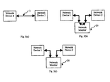
- FIGs 1(a) to 1(c) In particular, in Figure 1(a) there is shown two network devices 1,2 connected by a link 3. In Figure 1(b) there is shown an in-line connection of a network monitor 4 between the two network devices 1,2. In Figure 1(c) there is shown the connection of the network monitor 4 to the span port output 5 of a network switch or router 6. The method of gaining access to data on the network link is commonly referred to as "tapping".
- In-line tapping may be achieved using passive or active tapping methods. Both of these methods require that the insertion into the network be unobtrusive so as not to affect the transmission of data between the devices on the network.
- An active tap re-drives the network data passing though it, typically using a retimer circuit which regenerates the signal, restoring signal amplitude and timing, thus restoring signal integrity such that the ongoing signal passed back to the network is not degraded.
- an active tap may have to buffer and re-time the data in order to pass data between the two network segments.
- a passive tap does not provide for any regeneration of the signal.
- SERDES serialiser-deserialiser
- a network monitor that taps data from a network link between two network devices
- the network monitor comprising: first and second interfaces that allow the network monitor to be connected in-line in a network link between two network devices and to receive serial data therefrom and to transmit serial data thereto, each interface providing for serial-to-parallel conversion of data such that serial data received from a said network link at the interface is output as parallel data, and each interface providing for parallel-to-serial conversion of data such that parallel data received at the interface is output as serial data for transmission to a said network link; and, first and second programmable logic devices, the first programmable logic device being arranged to receive parallel data output by the first interface and to process said data for network analysis purposes, the second programmable logic device being arranged to receive parallel data output by the second interface and to process said data for network analysis purposes, each programmable logic device being controllable so as to selectively pass a copy of the received parallel data to the other programmable logic device so that the network monitor
- programmable logic devices to perform the data connection between two channels provides flexible control over the routing of the data as their programmability allows their function to be changed during normal operation. This is particularly useful as it allows the network monitor to dynamically switch between operating as an in-line or end station monitoring device.
- standard interfaces such as physical layer (PHY) ICs, are used, which provide a cost-effective method of providing an interface to allow the network monitor to be interfaced with a network link operating at several different speeds with different signalling technologies.
- PHY physical layer
- the preferred embodiment of the present invention enables active tapping of data from any serial data network protocol and particularly an Ethernet network operating at 10, 100 and 1000 Base-T with data rates of 10, 100 and 1000 Megabits per second, respectively.
- the preferred embodiment may also be applied to 10 GBase-T, operating at 10 Gbps, which has yet to be fully specified and implemented.
- the monitor comprises a first parallel data frequency and width adjuster between the first interface and the first programmable logic device, the first parallel data frequency and width adjuster being constructed and arranged to reduce the frequency and to increase the width of parallel data received from the first interface by a predetermined amount prior to said data being passed to the first programmable logic device; and, a second parallel data frequency and width adjuster between the second programmable logic device and the second interface, the second parallel data frequency and width adjuster being constructed and arranged to increase the frequency and to reduce the width of parallel data received from the second programmable logic device by said predetermined amount prior to said data being transmitted to a said network link by the second interface when the network monitor is operating in in-line mode.
- the adjusting of data frequency and width facilitates the use of low cost programmable logic devices.
- the cost of a programmable logic device is typically proportional to its speed capability and therefore, programmable logic devices that operate at lower frequencies are cheaper.
- the first parallel data frequency and width adjuster is provided by a multiplexer and the second parallel data frequency and width adjuster is provided by a demultiplexer.
- the network monitor preferably comprises a third parallel data frequency and width adjuster between the second interface and the second programmable logic device, the third parallel data frequency and width adjuster being constructed and arranged to reduce the frequency and to increase the width of parallel data received from the second interface by a predetermined amount prior to said data being passed to the second programmable logic device; and, a fourth parallel data frequency and width adjuster between the first programmable logic device and the first interface, the fourth parallel data frequency and width adjuster being constructed and arranged to increase the frequency and to reduce the width of parallel data received from the first programmable logic device by said predetermined amount prior to said data being transmitted to a said network link by the first interface when the network monitor is operating in in-line mode.
- the third parallel data frequency and width adjuster is preferably provided by a multiplexer and the fourth parallel data frequency and width adjuster is preferably provided by a demultiplexer.
- the network monitor preferably comprises a clock signal provider for providing a clock signal so that data can be clocked through the network monitor.
- the clock signal provider is constructed and arranged to obtain said clock signal by recovering a clock signal from data received at the first and second interfaces respectively.
- the use of the recovered data clock to clock the data through the network monitor from the input of one channel though to the output of the opposite channel ensures that the data and clock remain synchronised throughout the network monitor. This minimises the skew between the clock and the data. It also removes the requirement for memory based buffering between channels, therefore reducing the component count or logic requirement inside the programmable logic devices.
- each programmable logic device is a field programmable gate array.
- a method of monitoring data on a network link comprising: receiving data in serial form from a network link; converting the data in serial form to data in parallel form; passing the parallel data to a first programmable logic device for processing for network analysis purposes; controlling the first programmable logic device such that the method takes place selectively in in-line mode or in end station mode, whereby in in-line mode the first programmable logic device provides a copy of the received parallel data, the copy of the received parallel data being converted to data in serial form, said serial data being transmitted back onto the network link, and whereby in end station mode the first programmable logic device does not provide a copy of the received parallel data for conversion into serial form and transmission back onto the network link.
- the method preferably comprises, after converting the data in serial form to data in parallel form, reducing the frequency and increasing the width of the parallel data by a predetermined amount prior to said parallel data being passed to the first programmable logic device; and, when operating in in-line mode, increasing the frequency and reducing the width of the copy of the parallel data by the predetermined amount prior to the copy of the parallel data being converted to data in serial form for transmission back onto the network link.
- the method preferably comprises recovering a clock signal from the data received in serial form from the network link and using the recovered clock signal when operating in in-line mode to clock the data throughout the step of converting of the data in serial form to the data in parallel form to the step of transmitting serial data being back onto the network link.
- FIG 3(a) there is shown two network devices 1,2 connected by a link 3.
- Figure 3(b) there is shown an in-line connection of an example of a network monitor 20 according to an embodiment of the present invention between the two network devices 1,2. Once inserted, the network monitor 20 is capable of disconnecting the in-line link to enable operation in end station mode as shown in Figure 3(c).
- the network monitor 20 uses two identical circuits, referred to as Channel 1 and Channel 2, to tap data from the network.
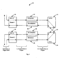
- the network monitor 20 uses pairs of four different functional blocks to implement each of these circuits as shown in Figure 4. These blocks are a physical layer IC 30, a multiplexer 40, field programmable gate array (FPGA) 50, and a de-multiplexer 60.
- FPGA field programmable gate array
- the physical layer (PHY) IC 30 provides the interface to the physical layer of the monitored network.
- the PHY IC 30 is preferably a multi-speed Ethernet PHY IC, which provides speed negotiation and signalling changes between the various speeds available on Ethernet.
- the PHY IC 30 performs serial-to-parallel conversion of the data entering the network monitor 20 from the network link.
- the PHY IC 30 also performs parallel-to-serial conversion of the data that is to be transmitted back onto the network link from the network monitor 20.
- the line-side and system-side interfaces of the PHY IC 30 may be industry standard. In practice, the PHY IC 30 may be changed to support different physical layers.
- the use of standard PHY ICs 30 provide a cost-effective method of providing an interface that allows the network monitor 20 to be interfaced with a network link operating at several different speeds with different signalling technologies.
- the multiplexer 40 interfaces the received parallel data from the PHY IC 20 to the FPGA 50.
- the multiplexer 40 applies a conversion factor X to the received data.
- the conversion factor is chosen so that the frequency of the data matches the capabilities of the chosen FPGA 50. This adjusting of the data frequency and width facilitates the use of low cost FPGAs 50.
- the cost of an FPGA is approximately proportional to its speed capability and thus FPGAs that operate at lower frequencies are cheaper. This method of decreasing the frequency by X and increasing the word width by X results in no loss of bandwidth.
- the FPGA 50 processes the data passed to it by the multiplexer 40.
- the FPGA 50 takes a copy of the data which it has been passed for processing purposes.
- the FPGA 50 passes a copy of the data to the FPGA 50 on the opposite channel if the network monitor 20 is operating in in-line mode. If required, the FPGA 50 on the opposite channel buffers the received data when the monitor 20 is operating in in-line mode. In this mode, the FPGA 50 on the opposite channel outputs the received parallel data to its associated de-multiplexer 60 for retransmission onto the network link.
- a control signal is sent to each FPGA 50 to reconfigure it such that a copy of the data received at each FPGA 50 from a channel is not passed to the other FPGA 50.
- the network monitor 20 can act as an end station for two channels simultaneously.
- FPGAs 50 or some other functionally equivalent programmable logic device, to perform the data connection between the two channels provides flexible control over the routing of the data through the network monitor 20 and thus allows the network monitor 20 to switch dynamically between in-line and end station modes. This is due to the flexibility provided by the reconfigurability of the FPGAs 50 or other programmable logic devices, allowing their function to be changed during normal operation.
- the de-multiplexer 60 interfaces the parallel data received from the FPGA 50 to the PHY IC 30.
- the conversion factor X of the de-multiplexer 60 and the multiplexer 40 should be the same to ensure that the retransmitted data rate matches the received data rate.
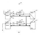
- a synchronous clock signal is used to clock the data 80 through each of the aforementioned functional blocks 30-60.
- a clock signal 70 can be provided by the PHY IC 30, which recovers a clock signal from the data 80 received from the network link. This recovered data clock, and/or its derivatives, is used to clock the data 80 through each of the four functional blocks 30-60, before clocking the data 80 into the PHY IC 30 of the opposite channel for retransmission back onto the network link.
- Figure 5 shows the flow of the clock signal 70 from Channel 1 to Channel 2 of the network monitor 20. The same arrangement is used to clock the transfer of data from Channel 2 to Channel 1.
- the frequency of the clock signal 70 may be decreased or increased by the conversion factor X as required in order to match changes in the frequency of the data 80 as it passes through each block 30-60.
- This use of the received data clock to clock the data through every stage of the network monitor 20 removes the need for re-timing the data. This is particularly valuable when the network monitor 20 is connected to a 1000 Base-T network. This arrangement minimises the skew between the clock and the data and removes the requirement for memory based buffering between channels, therefore reducing the component count or logic requirement inside the FPGAs 50.
- the flow of the clock signal 70 to the opposite channel only occurs during in-line mode.
- the clocks of the two channels are independent of each other.
Landscapes
- Engineering & Computer Science (AREA)
- Computer Networks & Wireless Communication (AREA)
- Signal Processing (AREA)
- Communication Control (AREA)
Claims (11)
- Netzwerküberwachungsgerät (20), das Daten von einer Netzwerkverbindung zwischen zwei Netzwerkvorrichtungen anzapft, wobei das Netzwerküberwachungsgerät Folgendes umfasst:erste und zweite Schnittstellen (30), die das zwischengeschaltete Verbinden des Netzwerküberwachungsgeräts (20) in einer Netzwerkverbindung zwischen zwei Netzwerkvorrichtungen und das Empfangen serieller Daten davon und das Übertragen serieller Daten dorthin ermöglichen, wobei jede Schnittstelle für seriell-parallele Umwandlung von Daten sorgt, derart, dass serielle Daten, die von der Netzwerkverbindung an der Schnittstelle (30) empfangen werden, als parallele Daten ausgegeben werden, und dass jede Schnittstelle (30) derart für parallel-serielle Umwandlung von Daten sorgt, dass parallele Daten, die an der Schnittstelle (30) empfangen werden, als serielle Daten zur Übertragung an die Netzwerkverbindung ausgegeben werden; underste und zweite programmierbare Logikschaltungen (50),wobei die erste programmierbare Logikschaltung (50) angeordnet ist, um parallele Daten, die durch die erste Schnittstelle (30) ausgegeben werden, zu empfangen, und die Daten zu Netzwerkanalysezwecken zu verarbeiten, wobei die zweite programmierbare Logikschaltung (50) angeordnet ist, um parallele Daten, die durch die zweite Schnittstelle (30) ausgegeben werden, zu empfangen und die Daten zu Netzwerkanalysezwecken zu verarbeiten, wobei jede programmierbare Logikschaltung (50) gesteuert werden kann, um selektiv eine Kopie der empfangenen parallelen Daten an die andere programmierbare Logikschaltung (50) weiterzugeben, derart, dass das Netzwerküberwa chungsgerät (20) im "in line"-Modus arbeiten kann, und keine Kopie der empfangenen parallelen Daten an die andere programmierbare Logikschaltung (50) weiterzugeben, derart, dass das Netzwerküberwachungsgerät (20) im "end station"-Modus arbeiten kann,wobei die zweite programmierbare Logikschaltung (50) angeordnet ist, um die Kopie der parallelen Daten, die von der ersten programmierbaren Logikschaltung (50) empfangen wird, an die zweite Schnittstelle (30) zur parallel-seriellen Umwandlung und zur Übertragung der seriellen Daten zurück zu der Netzwerkverbindung weiterzugeben, wenn das Netzwerküberwachungsgerät (20) im "in line"-Modus arbeitet,wobei die erste programmierbare Logikschaltung (50) angeordnet ist, um die Kopie der parallelen Daten, die von der zweiten programmierbaren Logikschaltung (50) empfangen wird, an die erste Schnittstelle (30) zur parallel-seriellen Umwandlung und zur Übertragung der seriellen Daten zurück zu der Netzwerkverbindung weiterzugeben, wenn das Netzwerküberwachungsgerät (20) im "in line"-Modus arbeitet.
- Netzwerküberwachungsgerät (20) nach Anspruch 1, das Folgendes umfasst:einen ersten Paralleldatenfrequenz- und Breitenregler zwischen der ersten Schnittstelle (30) und der ersten programmierbaren Logikschaltung (50), wobei der erste Paralleldatenfrequenz- und Breitenregler zum Verringern der Frequenz und zum Vergrößern der Breite von parallelen Daten (80), die von der ersten Schnittstelle (30) empfangen werden, um einen vorbestimmten Betrag, bevor die Daten (80) an die erste programmierbare Logikschaltung (50) weitergegeben werden, konstruiert und angeordnet ist; undeinen zweiten Paralleldätenfrequenz- und Breitenregler zwischen der zweiten programmierbaren Logikschaltung (50) und der zweiten Schnittstelle (30), wobei der zweite Paralleldatenfrequenz- und Breitenregler zum Erhöhen der Frequenz und zum Verkleinern der Breite von parallelen Daten (80), die von der zweiten programmierbaren Logikschaltung (50) empfangen werden, um den vorbestimmten Betrag, bevor die Daten (80) durch die zweite Schnittstelle (30) an die Netzwerkverbindung übertragen werden, konstruiert und angeordnet ist, wenn das Netzwerküberwachungsgerät (20) im "in line"-Modus arbeitet.
- Netzwerküberwachungsgerät (20) nach Anspruch 2, wobei der erste Paralleldatenfrequenz- und Breitenregler durch einen Multiplexer (40) bereitgestellt wird, und der zweite Paralleldatenfrequenz- und Breitenregler durch einen Demultiplexer (60) bereitgestellt wird.
- Netzwerküberwachungsgerät (20) nach Anspruch 2 oder Anspruch 3, das Folgendes umfasst:einen dritten Paralleldatenfrequenz- und Breitenregler zwischen der zweiten Schnittstelle (30) und der zweiten programmierbaren Logikschaltung (50), wobei der dritte Paralleldatenfrequenz- und Breitenregler zum Verringern der Frequenz und zum Vergrößern der Breite von parallelen Daten (80), die von der zweiten Schnittstelle (30) empfangen werden, um einen vorbestimmten Betrag, bevor die Daten (80) an die zweite programmierbare Logikschaltung (50) weitergeben werden, konstruiert und angeordnet ist; undeinen vierten Paralleldatenfrequenz- und Breitenregler zwischen der ersten programmierbaren Logikschaltung (50) und der ersten Schnittstelle (30), wobei der vierte Paralleldatenfrequenz- und Breitenregler zum Erhöhen der Frequenz und zum Verkleinern der Breite von parallelen Daten (80), die von der ersten programmierbaren Logikschaltung (50) empfangen werden, um den vorbestimmten Betrag, bevor die Daten (80) durch die erste Schnittstelle (30) an die Netzwerkverbindung übertragen werden, konstruiert und angeordnet ist, wenn das Netzwerküberwachungsgerät (20) im "in line"-Modus arbeitet.
- Netzwerküberwachungsgerät (20) nach Anspruch 4, wobei der dritte Paralleldatenfrequenz- und Breitenregler durch einen Multiplexer (40) bereitgestellt wird, und der vierte Paralleldatenfrequenz- und Breitenregler durch einen Demultiplexer (60) bereitgestellt wird.
- Netzwerküberwachungsgerät (20) nach einem der Ansprüche 1 bis 5, das einen Taktsignalgeber zum Bereitstellen eines Taktsignals (70) umfasst, derart, dass die Daten (80) durch das Netzwerküberwachungsgerät getaktet werden können.
- Netzwerküberwachungsgerät (20) nach Anspruch 6, wobei der Taktsignalgeber konstruiert und angeordnet ist, um das Taktsignal (70) durch Rückgewinnen eines Taktsignals von Daten (80), die an den ersten beziehungsweise zweiten Schnittstellen (30) empfangen werden, zu erhalten.
- Netzwerküberwachungsgerät (20) nach einem der Ansprüche 1 bis 7, wobei jede programmierbare Logikschaltung (50) ein feldprogrammierbares Gate-Array ist.
- Verfahren zum Überwachen von Daten auf einer Netzwerkverbindung, wobei das Verfahren Folgendes umfasst:Empfangen von Daten in serieller Form von einer Netzwerkverbindung;Umwandeln der Daten in serieller Form in Daten in paralleler Form;Weitergeben der parallelen Daten an eine erste programmierbare Logikschaltung (50) zum Verarbeiten zu Netzwerkanalysezwecken;Steuern der ersten programmierbaren Logikschaltung (50) derart, dass das Verfahren selektiv im "in line"-Modus oder im "end station"-Modus erfolgt,wobei im "in line"-Modus die erste programmierbare Logikschaltung (50) eine Kopie der empfangenen parallelen Daten (80) bereitstellt,
wobei die Kopie der empfangenen parallelen Daten (80) in Daten in serieller Form umgewandelt wird, wobei die seriellen Daten zurück an die Netzwerkverbindung übertragen werden, und
wobei im "end station"-Modus die erste programmierbare Logikschaltung (50) keine Kopie der empfangenen parallelen Daten (80) zur Umwandlung in serielle Form und zur Übertragung zurück auf die Netzwerkverbindung bereitstellt. - Verfahren nach Anspruch 9, das Folgendes umfasst:nach dem Umwandeln der Daten (80) in serieller Form in Daten in paralleler Form, Verringern der Frequenz und Vergrößern der Breite der parallelen Daten um einen vorbestimmten Betrag, bevor die parallelen Daten (80) an die erste programmierbare Logikschaltung (50) weitergegeben werden; undwenn im "in line"-Modus gearbeitet wird, Erhöhen der Frequenz und Verkleinern der Breite der Kopie der parallelen Daten (80) um den vorbestimmten Betrag, bevor die Kopie der parallelen Daten (80) zur Übertragung zurück auf die Netzwerkverbindung in Daten in serieller Form umgewandelt wird.
- Verfahren nach Anspruch 9 oder Anspruch 10, das das Rückgewinnen eines Taktsignals von den Daten, die in serieller Form von der Netzwerkverbindung empfangen werden, und das Verwenden des rückgewonnenen Taktsignals, wenn im "in line"-Modus gearbeitet wird, zum Takten der Daten über den Schritt des Umwandelns der Daten in serieller Form in Daten in paralleler Form hinweg zum Schritt des Übertragens von seriellen Daten, die auf der Netzwerkverbindung zurück sind, umfasst.
Applications Claiming Priority (3)
| Application Number | Priority Date | Filing Date | Title |
|---|---|---|---|
| US40270402P | 2002-08-13 | 2002-08-13 | |
| US402704P | 2002-08-13 | ||
| PCT/GB2003/003210 WO2004015921A1 (en) | 2002-08-13 | 2003-07-30 | Network monitor and method |
Publications (2)
| Publication Number | Publication Date |
|---|---|
| EP1529373A1 EP1529373A1 (de) | 2005-05-11 |
| EP1529373B1 true EP1529373B1 (de) | 2007-04-11 |
Family
ID=31715885
Family Applications (1)
| Application Number | Title | Priority Date | Filing Date |
|---|---|---|---|
| EP03784232A Expired - Lifetime EP1529373B1 (de) | 2002-08-13 | 2003-07-30 | Netzwerküberwachungsgerät und -verfahren |
Country Status (5)
| Country | Link |
|---|---|
| US (1) | US7411946B2 (de) |
| EP (1) | EP1529373B1 (de) |
| AU (1) | AU2003248951A1 (de) |
| DE (1) | DE60313179T2 (de) |
| WO (1) | WO2004015921A1 (de) |
Families Citing this family (19)
| Publication number | Priority date | Publication date | Assignee | Title |
|---|---|---|---|---|
| US7613837B2 (en) * | 2003-03-31 | 2009-11-03 | Gordy Stephen C | Network tap with interchangeable ports |
| US7281167B2 (en) * | 2003-08-26 | 2007-10-09 | Finisar Corporation | Multi-purpose network diagnostic modules |
| US20050129033A1 (en) * | 2003-12-13 | 2005-06-16 | Gordy Stephen C. | Network tap for use with multiple attached devices |
| US8565095B2 (en) * | 2005-04-19 | 2013-10-22 | Alcatel Lucent | Context controlled data tap utilizing parallel logic for integrated link monitoring |
| US20070189175A1 (en) * | 2006-02-14 | 2007-08-16 | Finisar Corporation | Capture timing and negotiation data with repeat counts in a networking diagnostic component |
| US8607145B2 (en) * | 2006-02-14 | 2013-12-10 | Jds Uniphase Corporation | Show OOB and speed negotiation data graphically in a network diagnostic component |
| US8125906B2 (en) * | 2006-03-03 | 2012-02-28 | Kiranmai Vedanabhatla | Capture RCDT and SNTT SAS speed negotiation decodes in a network diagnostic component |
| US8576731B2 (en) * | 2006-02-14 | 2013-11-05 | Jds Uniphase Corporation | Random data compression scheme in a network diagnostic component |
| US7673184B2 (en) * | 2006-02-14 | 2010-03-02 | Jds Uniphase Corporation | Flow control methodology for digital retiming devices |
| US8769152B2 (en) | 2006-02-14 | 2014-07-01 | Jds Uniphase Corporation | Align/notify compression scheme in a network diagnostic component |
| ATE506784T1 (de) * | 2007-03-09 | 2011-05-15 | Mentor Graphics Corp | Hardware-schnittstellenbaugruppe zum verbinden eines emulators mit einem netzwerk |
| US7792046B2 (en) * | 2008-06-05 | 2010-09-07 | Vss Monitoring, Inc. | Ethernet switch-based network monitoring system and methods |
| US20100290354A1 (en) * | 2009-05-15 | 2010-11-18 | Vss Monitoring, Inc. | Method for determining ethernet mode of operation during passive monitoring |
| US10503690B2 (en) * | 2018-02-23 | 2019-12-10 | Xilinx, Inc. | Programmable NOC compatible with multiple interface communication protocol |
| US11056232B2 (en) | 2019-08-18 | 2021-07-06 | Medigate tech Ltd. | Medication usage auditing based on analysis of infusion pump network traffic |
| US10825566B1 (en) | 2019-08-18 | 2020-11-03 | Medigate tech Ltd. | Ensuring availability of medical devices to receive maintenance |
| US10658079B1 (en) | 2019-08-18 | 2020-05-19 | Medigate tech Ltd. | Crowd-based recommendations of a version of firmware for medical devices |
| US10600512B1 (en) | 2019-08-18 | 2020-03-24 | Medigate tech Ltd. | Network-based calculation of prevalence of repeated medical imaging |
| CN114268674A (zh) * | 2020-09-15 | 2022-04-01 | 西安诺瓦星云科技股份有限公司 | 视频处理设备及视频预监方法 |
Family Cites Families (6)
| Publication number | Priority date | Publication date | Assignee | Title |
|---|---|---|---|---|
| US4064360A (en) * | 1976-07-06 | 1977-12-20 | The United States Of America As Represented By The Secretary Of The Navy | High speed digital switch |
| EP0661848B1 (de) | 1993-12-28 | 2001-09-05 | NEC Corporation | Überwachungs- und Steuereinrichtung für Kommunikationseinrichtung |
| US5548590A (en) | 1995-01-30 | 1996-08-20 | Hewlett-Packard Company | High performance frame time monitoring system and method for a fiber optic switch for a fiber optic network |
| US6047321A (en) * | 1996-02-23 | 2000-04-04 | Nortel Networks Corporation | Method and apparatus for monitoring a dedicated communications medium in a switched data network |
| US5864486A (en) * | 1996-05-08 | 1999-01-26 | Lattice Semiconductor Corporation | Method and apparatus for in-system programming of a programmable logic device using a two-wire interface |
| US6888800B1 (en) | 1998-11-14 | 2005-05-03 | Emulex Design & Manufacturing Corporation | High performance digital loop diagnostic technology |
-
2003
- 2003-07-30 AU AU2003248951A patent/AU2003248951A1/en not_active Abandoned
- 2003-07-30 EP EP03784232A patent/EP1529373B1/de not_active Expired - Lifetime
- 2003-07-30 US US10/524,528 patent/US7411946B2/en not_active Expired - Lifetime
- 2003-07-30 WO PCT/GB2003/003210 patent/WO2004015921A1/en not_active Ceased
- 2003-07-30 DE DE60313179T patent/DE60313179T2/de not_active Expired - Fee Related
Non-Patent Citations (1)
| Title |
|---|
| None * |
Also Published As
| Publication number | Publication date |
|---|---|
| EP1529373A1 (de) | 2005-05-11 |
| US20060153177A1 (en) | 2006-07-13 |
| DE60313179T2 (de) | 2007-12-27 |
| AU2003248951A1 (en) | 2004-02-25 |
| DE60313179D1 (de) | 2007-05-24 |
| WO2004015921A1 (en) | 2004-02-19 |
| US7411946B2 (en) | 2008-08-12 |
Similar Documents
| Publication | Publication Date | Title |
|---|---|---|
| EP1529373B1 (de) | Netzwerküberwachungsgerät und -verfahren | |
| US7362797B2 (en) | Physical layer device having an analog SERDES pass through mode | |
| CN113810317B (zh) | 具有冗余数据路径的物理层接口 | |
| US6424627B1 (en) | Full-duplex medium tap apparatus and system | |
| US8599913B1 (en) | Data regeneration apparatus and method for PCI express | |
| US6754238B1 (en) | Method and apparatus for transport of control information over a data link | |
| US9143464B2 (en) | Method and system for speed negotiation for twisted pair links using intelligent E-FIFO in fibre channel systems | |
| WO2001086878A2 (en) | System and process for embedded cable modem in a cable modem termination system to enable diagnostics and monitoring | |
| US11646959B2 (en) | Active ethernet cable with broadcasting and multiplexing for data path redundancy | |
| CN103889008A (zh) | 支持高速无线接入点的以太网介质转换器 | |
| US7555574B2 (en) | Asymmetric data path media access controller | |
| US20010003484A1 (en) | Optical line protection device and optical line protection method | |
| US9729472B2 (en) | Network physical link (PHY) switch system | |
| CA2408496A1 (en) | System and process for return channel spectrum manager | |
| WO2003081785A1 (en) | Physcial layer device having an analog serdes pass through mode | |
| WO2021061348A1 (en) | Complementary data flow for noise reduction | |
| US20060010336A1 (en) | Connection apparatus and method for network testers and analysers | |
| CN114050865B (zh) | 一种数据传输装置、芯片及电子设备 | |
| Iniewski et al. | SerDes technology for gigabit I/O communications in storage area networking | |
| US7266624B1 (en) | Programmable layered sub-system interface | |
| WO2025167343A1 (zh) | 一种芯片、处理装置和电子设备 | |
| JP2001007833A (ja) | インターフェース変換装置 |
Legal Events
| Date | Code | Title | Description |
|---|---|---|---|
| PUAI | Public reference made under article 153(3) epc to a published international application that has entered the european phase |
Free format text: ORIGINAL CODE: 0009012 |
|
| 17P | Request for examination filed |
Effective date: 20050210 |
|
| AK | Designated contracting states |
Kind code of ref document: A1 Designated state(s): AT BE BG CH CY CZ DE DK EE ES FI FR GB GR HU IE IT LI LU MC NL PT RO SE SI SK TR |
|
| AX | Request for extension of the european patent |
Extension state: AL LT LV MK |
|
| DAX | Request for extension of the european patent (deleted) | ||
| RBV | Designated contracting states (corrected) |
Designated state(s): DE FR GB |
|
| GRAP | Despatch of communication of intention to grant a patent |
Free format text: ORIGINAL CODE: EPIDOSNIGR1 |
|
| GRAS | Grant fee paid |
Free format text: ORIGINAL CODE: EPIDOSNIGR3 |
|
| GRAA | (expected) grant |
Free format text: ORIGINAL CODE: 0009210 |
|
| RIN1 | Information on inventor provided before grant (corrected) |
Inventor name: CARTER, BRIAN, R. Inventor name: WIDLEY, GARRY Inventor name: WORRALL, A.C. |
|
| AK | Designated contracting states |
Kind code of ref document: B1 Designated state(s): DE FR GB |
|
| REG | Reference to a national code |
Ref country code: GB Ref legal event code: FG4D |
|
| REF | Corresponds to: |
Ref document number: 60313179 Country of ref document: DE Date of ref document: 20070524 Kind code of ref document: P |
|
| ET | Fr: translation filed | ||
| PLBE | No opposition filed within time limit |
Free format text: ORIGINAL CODE: 0009261 |
|
| STAA | Information on the status of an ep patent application or granted ep patent |
Free format text: STATUS: NO OPPOSITION FILED WITHIN TIME LIMIT |
|
| 26N | No opposition filed |
Effective date: 20080114 |
|
| PG25 | Lapsed in a contracting state [announced via postgrant information from national office to epo] |
Ref country code: DE Free format text: LAPSE BECAUSE OF NON-PAYMENT OF DUE FEES Effective date: 20080201 |
|
| REG | Reference to a national code |
Ref country code: FR Ref legal event code: ST Effective date: 20080331 |
|
| PG25 | Lapsed in a contracting state [announced via postgrant information from national office to epo] |
Ref country code: FR Free format text: LAPSE BECAUSE OF NON-PAYMENT OF DUE FEES Effective date: 20070731 |
|
| PGFP | Annual fee paid to national office [announced via postgrant information from national office to epo] |
Ref country code: GB Payment date: 20080520 Year of fee payment: 6 |
|
| GBPC | Gb: european patent ceased through non-payment of renewal fee |
Effective date: 20090730 |
|
| PG25 | Lapsed in a contracting state [announced via postgrant information from national office to epo] |
Ref country code: GB Free format text: LAPSE BECAUSE OF NON-PAYMENT OF DUE FEES Effective date: 20090730 |