EP1529350B1 - Pilotsymbole in kommunikationssystemen - Google Patents
Pilotsymbole in kommunikationssystemen Download PDFInfo
- Publication number
- EP1529350B1 EP1529350B1 EP03810340A EP03810340A EP1529350B1 EP 1529350 B1 EP1529350 B1 EP 1529350B1 EP 03810340 A EP03810340 A EP 03810340A EP 03810340 A EP03810340 A EP 03810340A EP 1529350 B1 EP1529350 B1 EP 1529350B1
- Authority
- EP
- European Patent Office
- Prior art keywords
- pilot symbols
- frequency
- symbols
- data stream
- data
- Prior art date
- Legal status (The legal status is an assumption and is not a legal conclusion. Google has not performed a legal analysis and makes no representation as to the accuracy of the status listed.)
- Expired - Lifetime
Links
- 238000004891 communication Methods 0.000 title claims abstract description 15
- 238000000034 method Methods 0.000 claims abstract description 96
- 230000001788 irregular Effects 0.000 claims abstract description 24
- 238000009826 distribution Methods 0.000 claims abstract description 17
- 238000012545 processing Methods 0.000 claims abstract description 9
- 230000008569 process Effects 0.000 claims description 13
- 230000005540 biological transmission Effects 0.000 claims description 7
- 238000012937 correction Methods 0.000 claims description 7
- 238000004364 calculation method Methods 0.000 claims description 3
- 230000003247 decreasing effect Effects 0.000 claims description 3
- 238000007670 refining Methods 0.000 claims description 2
- 230000004044 response Effects 0.000 description 15
- 230000001427 coherent effect Effects 0.000 description 13
- 238000005562 fading Methods 0.000 description 8
- 239000013598 vector Substances 0.000 description 7
- 238000004458 analytical method Methods 0.000 description 5
- 238000013459 approach Methods 0.000 description 5
- 238000010586 diagram Methods 0.000 description 3
- 230000006872 improvement Effects 0.000 description 3
- 238000001228 spectrum Methods 0.000 description 3
- 230000015556 catabolic process Effects 0.000 description 2
- 230000008859 change Effects 0.000 description 2
- 238000006731 degradation reaction Methods 0.000 description 2
- 230000000694 effects Effects 0.000 description 2
- 238000004519 manufacturing process Methods 0.000 description 2
- 230000009467 reduction Effects 0.000 description 2
- 101150065184 sym-2 gene Proteins 0.000 description 2
- 238000007476 Maximum Likelihood Methods 0.000 description 1
- 238000007792 addition Methods 0.000 description 1
- 238000010420 art technique Methods 0.000 description 1
- 238000005352 clarification Methods 0.000 description 1
- 238000007796 conventional method Methods 0.000 description 1
- 230000002939 deleterious effect Effects 0.000 description 1
- 238000003780 insertion Methods 0.000 description 1
- 230000037431 insertion Effects 0.000 description 1
- 238000012804 iterative process Methods 0.000 description 1
- 238000010295 mobile communication Methods 0.000 description 1
- 238000009828 non-uniform distribution Methods 0.000 description 1
- 230000010363 phase shift Effects 0.000 description 1
- 238000007781 pre-processing Methods 0.000 description 1
- 239000004576 sand Substances 0.000 description 1
- 238000000926 separation method Methods 0.000 description 1
- 230000001629 suppression Effects 0.000 description 1
- 230000001360 synchronised effect Effects 0.000 description 1
Images



Classifications
-
- H—ELECTRICITY
- H04—ELECTRIC COMMUNICATION TECHNIQUE
- H04B—TRANSMISSION
- H04B1/00—Details of transmission systems, not covered by a single one of groups H04B3/00 - H04B13/00; Details of transmission systems not characterised by the medium used for transmission
- H04B1/76—Pilot transmitters or receivers for control of transmission or for equalising
-
- H—ELECTRICITY
- H04—ELECTRIC COMMUNICATION TECHNIQUE
- H04L—TRANSMISSION OF DIGITAL INFORMATION, e.g. TELEGRAPHIC COMMUNICATION
- H04L25/00—Baseband systems
- H04L25/02—Details ; arrangements for supplying electrical power along data transmission lines
- H04L25/0202—Channel estimation
- H04L25/0224—Channel estimation using sounding signals
- H04L25/0226—Channel estimation using sounding signals sounding signals per se
-
- H—ELECTRICITY
- H04—ELECTRIC COMMUNICATION TECHNIQUE
- H04L—TRANSMISSION OF DIGITAL INFORMATION, e.g. TELEGRAPHIC COMMUNICATION
- H04L27/00—Modulated-carrier systems
- H04L27/0014—Carrier regulation
- H04L2027/0083—Signalling arrangements
- H04L2027/0097—Adaptive synchronisation signals
Definitions
- This invention relates to signal processing in telecommunications, particularly but not exclusively for use in wireless TDMA systems.
- the invention concerns methods for use in communication systems making use of pilot symbols.
- Pilot symbol assisted modulation is a known method used to reduce effects of fading and other distortion factors in mobile communications, by periodically inserting known pilot symbols in the signal data stream. Since the transmitted pilot symbols are known, the receiver can make use of these regularly spaced pilot symbols to derive the amplitude and phase reference of the received signal. Channel estimators are used to determine the amplitude and phase reference at the known pilot symbols, providing correction factors that can then be interpolated and applied to the other symbols (data symbols) in the signal. There is, in general, a tradeoff between the complexity of the acquisition algorithm and its robustness. Two types of algorithms used for frequency acquisition are differential decoding and coherent correlation (see below).
- the robustness of frequency estimation for a data packet in noise depends on the pattern of pilot symbols throughout the packet.
- the most robust methods use the Fourier Transform. In this method, the data symbols are identified and removed, leaving the pilot symbols.
- a Fourier Transform (typically, the Fast Fourier Transform - FFT) is then applied to the resulting packet in order to identify the maximum-likelihood frequency.
- Pilot symbols do not carry any data, and it is therefore necessary to keep them to as few as possible. However, too few pilot symbols can result in performance degradation due to poor channel estimation. The trade-off between pilot symbol spacing and the symbol error rate is therefore an important consideration for system of this type.
- UW Unique Words
- BPSK binary phase shift keying
- Coherent correlation methods are comparatively fast.
- the majority of the pilot symbols are in a UW at the front of the packet.
- a frequency offset is applied to the UW symbols before they are summed.
- symbols in the UW can cancel one another, and the SNR will thus be significantly decreased.
- coherent correlation must be repeated at a number of different frequency offsets, such that at least one frequency option is sufficiently close to the actual frequency. This repetition increases the complexity, and the technique is less robust than the Fourier Transform frequency response method described above.
- Differential decoding methods are also comparatively fast, and they need not deal with coherence issues. However, they decrease the effective SNR by multiplying noise data symbols together. To overcome this, differential decoding must be repeated at several different time-offsets, which once again increases the algorithm complexity. The technique cannot improve on a performance dictated by the pattern of pilot symbols.
- the invention provides in accordance with a first aspect a method of placing pilot symbols in a data stream for telecommunication systems, the distribution of pilot symbols involving repetitions of irregular groupings of pilot symbols in the data stream and the data stream comprising a data packet, characterised in that the pilot symbols are placed with irregular spacing within a first level group, the irregular spacing being repeated in a plurality of such first level groups, and the first level groups are placed with irregular spacing within a second level group.
- the distribution of pilot symbols in time is substantially fractal in nature, the irregular groupings of pilot symbols themselves irregularly spaced in the data stream.
- the pilot symbols are placed with irregular spacing within a first level group (L0 level), the irregular spacing is repeated in a plurality of such L0 groups, and the L0 groups are placed with irregular spacing within a second level group (L1 level).
- the irregular spacing between the L0 groups is repeated in a plurality of L1 groups across the data packet, and the L1 groups are placed with irregular spacing within a third level group (L2 level).
- each L0 groups has length A
- each L1 group each has length B
- the L2 group has length C
- the pilot symbol distribution is selected such that the ratio A:B is approximately equal to the ratio B:C.
- the pilot symbols extend across substantially the entirery of the data packet.
- the spacing of the pilot symbols is decided in accordance with a mathematical relationship, such that their positions are substantially predictable, but sufficiently unevenly spaced to improve the ratio of the pilot symbol spectrum corresponding to the most likely frequency to that of the next most likely frequency, when compared with that available from an equivalent data stream containing evenly spaced pilot symbols.
- the invention provides a signal processing device for use in a communications system for generating a data stream for telecommunication systems, the signal processing device configured to implement the above defined method.
- a fractal is a mathematical pattern that has significant structure on several different length scales. Fractal patterns occur frequently in nature, of course, common examples being a coastline having gulfs, bays, inlets, boulders, pebbles and sand grains on different length scales, or a tree having boughs, branches and twigs on different length scales. In a fractal structure, there is new detail at each new length scale. On the other hand, a square has four corners, with simple straight lines between those corners. There is no new detail in a square that is smaller than the square itself.
- the pilot symbol pattern of the invention is thus built from sub-patterns that are repeated at irregular intervals, these sub-patterns themselves built up from smaller sub-patterns.
- This multi-scale structure allows a multi-scale approach to frequency estimation, as each scale (or level) of the pilot symbol pattern is used to find a frequency estimate.
- the multi-scale algorithm uses each frequency estimate to resolve potential aliasing errors in the next frequency estimate, until the most precise frequency estimate's aliasing has been resolved.
- the multi-scale algorithm is computationally efficient because is needs only find frequency estimates for a few simple patterns.
- the invention thus provides a new class of pilot symbol patterns that allow efficient acquisition of the data packet's time and frequency, as well as a novel algorithm for acquisition of the time and frequency offset.
- the pilot symbol pattern is particularly robust to phase noise, as the pilot symbols, though irregular, are placed with a uniform density throughout the packet.
- the pilot symbol pattern allows the spectrum of the pilot symbols to be narrower than that of the packet, thus reducing adjacent channel interference during acquisition.
- pilot symbol patterns can be selected for different users, with low cross-correlation.
- the method of the invention is computationally efficient when compared to data streams containing randomly placed pilot symbols.
- pilot symbol intervals have a mathematical relationship with each other they are sufficiently predictable to ensure that the computational power needed is significantly less than that required for randomly distributed pilot symbol schemes, yet sufficiently unevenly spaced to perform their intended function of substantially improving the signal to noise ratio.
- the packet structure includes small groups of pilot symbols, a plurality of these small groups grouped into a medium-level group, and a plurality of these medium-level groups grouped into a high-level group. At each level, then, there is a specific group structure. There is preferably no mathematical repetition of the group structure from one group level (length scale) to the next.
- the pilot symbols are spread in this pattern over the entirety, or almost the entirety, of the signal packet.
- a receiver method for receiving and acquiring a transmitted signal in a communications system including the steps of:
- a receiver method for receiving and acquiring a transmitted signal in a communications system including the steps of:
- the receiver method may include a process for further improving the reliability of acquisition by using additional encoded pilot symbols embedded within the data stream, the additional pilot symbols encoded with forward error correcting codes; the process including the steps in the receiver of:
- the receiver method may be enhanced by selecting in the data stream one or more of the pilot symbols and replacing them with data symbols, and applying the acquisition steps based on the assumption that these selected symbols are pilot symbols with zero value.
- a receiver for receiving and acquiring transmitted signals in a communications system, the signals representing a data stream including data symbols and pilot symbols distributed in accordance with any of the above method, the receiver including functional blocks for carrying out the steps of any of the above defined receiver methods.
- the method of the invention therefore uses an iterative process towards coherent signal acquisition, combining frequency estimates based on an a priori assumption of coherence between pilot symbols in the smallest subgroup, with frequency estimates based on an a priori assumption that pilot symbols in different subgroups are independent in phase.
- the method thus calculates phase differences between the smallest subgroups, which may include aliasing ambiguities (2 ⁇ ambiguities). This phase difference can then be used to recalculate the offset between pilot symbols in the smallest group, allowing the resolution of any aliasing ambiguities.
- the coarsest frequency estimate is used to resolve aliasing ambiguities in an intermediate frequency estimate, and the intermediate frequency estimate is used in turn to resolve aliasing ambiguities in the finest frequency estimate.
- the pilot symbols can be summed coherently to find the correct frequency.
- the method of the invention thus relies upon the estimation of just a small number of phase differences, one phase difference corresponding to each layer of the multi-scale (fractal) pattern of pilot symbols.
- the prior art uses both UWs and pilot symbols to determine and achieve the functions of signal acquisition (which requires coarse timing estimates), and determination of the correct frequency.
- the invention preferably uses pilot symbols alone to perform both these functions, substantially all pilot symbols being used to acquire both timing and frequency.
- the invention lends itself to a system capable of performing both functions using pilot symbols alone, rather than depending on contiguous blocks of consecutive symbols making up the UWs.
- the timing acquisition function is effectively distributed through the non-equispaced pilot symbols.
- the invention provides pilot symbol patterns shown to have better sidelobe suppression than those of the prior art, to which a computationally efficient acquisition algorithm can be applied.
- the relatively regular structure of the pilot symbol pattern of the invention allows a rapid calculation of the data packet's most likely frequency, while the irregular intervals assist in reducing the sidelobes.
- the present invention is demonstrated to have superior packet error rate performance, using less 'overhead' data, thus improving the effective throughput data rate.
- a reduction in the signal to noise ratio allows lower signal power or greater symbol rate, whilst the use of a larger bandwidth allows more effective preprocessing of the incoming data.
- the present invention therefore provides improved reliability of acquisition of a data packet in the presence of noise, fading factors, or other deleterious effects. In comparison with prior art approaches it involves a smaller cost in pilot symbols and/or improved acquisition over a broader bandwidth.
- the invention can be applied to sub-carrier based modulation systems (OFDM) and TDMA systems, for example. In addition, it can be applied to block-based estimators for short-packet data streams and sliding-window estimators for long-packet or continuous transmission data streams.
- the communications system of this embodiment of the invention involves a source TDMA signal including pilot symbols in the stream of data symbols, which is passed through a communications interface and received at a receiver.
- the received signal is processed to separate the pilot symbols from the data symbols.
- the time and frequency of the pilot symbols are known to the receiver (as are the pilot symbols themselves), so that channel estimation can be carried out on the data symbols.
- phase noise rotates the received symbols by an amount that can vary, and it is thus necessary to calculate a phase error correction value in order that phase error can be suppressed.
- the conventional technique is to select a set of postulates defining possible frequency errors, to generate a set of error-compensated pilot symbols by each of said postulates, to generate a metric giving the likelihood of the frequency error being correct, and thus to select the frequency in accordance with this metric. Additionally, it is necessary to correct the time alignment in the signal.
- pilot symbols and data symbols are known to the person skilled in the art and will not be described in further detail here.
- the acquisition routine must find the frequency and time that a packet is received.
- the Unique Word method (UW) transmits a known data stream to assist with the task.
- a disadvantage of using only two UWs is that no information is available to distinguish between frequency offset possibilities. Instead, as the present invention appreciates, a structure is required with information on multiple length-scales. The invention provides such a structure, involving a UW based on a fractal.
- a fractal is a mathematical pattern that has significant structure on a plurality of different length scales.
- An example of a mathematical fractal is the Cantor set, formed by starting with the number line between 0 and 1, removing the middle third, leaving a segment at either end, removing the middle third of each segment, leaving four (irregularly spaced) segments, and then continuing to remove the middle third of each segment.
- the resulting pattern is thus made up of four clumps of entries, each clump built up of four smaller clumps, and so on.
- the set of symbols in a TDMA packet is finite, so the pattern is not a true fractal.
- the structures described below have patterns on at least three length scales, but the skilled reader will appreciate that a distribution having two or more length scales two is embraced by the present invention.
- fractal geometry In accordance with fractal geometry, a fractal cannot be treated as existing strictly in one, two, or any other whole-number dimensions. Instead, it must be handled mathematically as though it has some fractional dimension.
- the UWs of the prior art are formed from contiguous blocks of pilot symbols.
- the groupings in accordance with the invention and described below have pilot symbols placed irregularly throughout the packet. This pattern has information on all length-scales, so it can resolve ambiguities, but the pattern repeats sufficiently regularly to deal with noise in a methodical way. Additionally, by using pilot symbols throughout the packet, fading can be more reliably tracked than hitherto possible.
- the pattern of pilot symbols is ideally spread across most of the packet.
- the longer patterns afford more precise frequency estimates and do not allow as much phase drift, but are less resistant to aliasing.
- the acquisition method begins with the assumption that the symbols within the smallest sub-groups are coherent.
- this assumption will lead to reduced performance, and the smallest subgroups are therefore selected to be short in order to provide resistance to large frequency offsets.
- phase noise in which the phase drifts slowly in a random fashion.
- the pilot symbols may be used to recover the phase.
- the broadest subgroups should be spread across the packet, limiting the widest gap between pilot symbols.
- the coarsest frequency estimate is used to resolve aliasing in the intermediate frequency estimate, while the intermediate frequency estimate is used to resolve aliasing in the finest frequency estimate.
- the intermediate length-scale should be approximately midway between the shortest groupings and the whole packet. Mathematically, if the shortest sub-patterns have length A, the intermediate patterns have length B, and the whole packet has length C, then the ratios should be similar, A:B ⁇ B:C
- Each pattern's frequency response is used to give a final metric, being the ratio between the main beam's power and the highest sidelobes.
- the exact pattern thus depends on factors including the level of phase noise expected, and the need to balance aliasing problems against the precision of the frequency estimation.
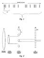
- Figure 1 illustrates placement of pilot symbols within a packet of data.
- Each line represents a pilot symbol, and these can be seen as structured into groups at different levels (different length-scales).
- L0 represents a group of pilot symbols, as does L1 and L2.
- the L2 group includes all the pilot symbols in the packet, including the L1 groups.
- the L1 group includes the L0 group as shown.
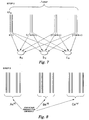
- FIG. 2 schematically illustrates the receiver acquisition process of a signal with unknown frequency 21.
- the acquisition process involves, firstly, an approximation of the medium frequency estimate using the L1 group (involving several sub-steps), followed by a coarse frequency estimate using pilot symbols within the same L0 group, followed by a fine frequency estimate using the L2 group.
- the coarse frequency estimate is referenced in the diagram at 22, the medium frequency estimate using pilot symbols within the L1 group, to resolve the 2 ⁇ ambiguities, at 23, and the fine frequency estimate - using coherent summing of all pilot symbols within the L2 group - at 24.
- the acquisition process is described in further detail below.
- the frequency response of a pattern of pilot symbols may be defined by forming a vector of numbers, with length equal to the packet length, placing a 1 in each entry that corresponds to a pilot symbol, and a 0 in all other entries, that correspond to data symbols.
- the frequency response is then the Fourier transform of this vector.
- Figure 3 illustrates the frequency response of two contiguous blocks of pilot symbols (the absolute values of the Fourier coefficients), in accordance with the prior art approach, whilst Figure 4 illustrates the type of frequency response achievable by the method of the present invention.
- Figure 5 shows the typical frequency response of a method using purely randomly spaced pilot symbols. This illustrates a strong centre frequency, but at the cost of very high computational load.
- the procedure therefore involves three particular levels of frequency estimation.
- the first provides a coarse frequency estimate with no aliasing.
- the last provides a precise frequency estimate with much aliasing.
- the frequency estimate from the intermediate level provides intermediate precision with some (but little) aliasing.
- the three phase differences have to be used to calculate three frequency estimates (referred to as the coarse, intermediate and fine frequency) and then combined into a single, unambiguous frequency estimate. Initially, both intermediate and fine frequency estimates have aliasing.
- TREAT pilot symbols in same L0 as coherent in phase It is thus assumed at this step that adjacent pilot symbols in an L0 group are mutually in phase, so can be coherently summed to produce the phase estimate, in order to reduce noise.
- TREAT pilot symbols in different L1 as independent in phase Estimate phase differentials at the L1 level.
- the result of this step is ⁇ , ⁇ , ⁇ , the phase differences between L0 groups within each L1 group. It should be noted that this may include 2 ⁇ ambiguities, as referred to above.
- the method therefore allows coherent combination of the four L0 groups. as the ⁇ , ⁇ , ⁇ is repeated within the four groups. This combination again reduces the effect of noise, and is of course insensitive to any 2 ⁇ ambiguities.
- the result of this step is phase differences a, b & c, resolving any 2 ⁇ ambiguity in ⁇ , ⁇ , and ⁇ .
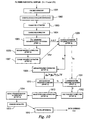
- FIG 9. A system block diagram is shown in FIG 9.
- the received signal is passed through an Analogue Digital Converter 901, then filtered by filter module 902, and passed to receiver acquisition block 903, giving an output synchronised data symbols for further processing.
- the first step is symbol time estimation.
- the upsampled data stream is input at functional block 1001.
- the data is over-sampled, and inter-symbol samples tend to be lower power than on-symbol samples, so the data set is used to estimate the fine time-offset.
- the output is then used to down-sample the packet at functional block 1002, to output the downsampled data stream.
- the next step is the coarse time estimation at functional block 1003.
- the procedure for frequency estimation (see below) is followed for each possible time offset.
- a likelihood score is found for the most likely frequency at each time offset.
- the time and frequency with the most likely response is then selected.
- the samples in the data stream are selected that correspond to pilot symbols, assuming the given time offset is correct, the output being 64 complex numbers.
- an initial medium frequency estimate is formed at functional block 1005, assuming the coarse frequency offset is zero. This is done by summing symbols within each L0 group, and using differential decoding within each L1 group to find an initial medium frequency estimate. This will be ambiguous, and will be degraded by the poor coarse frequency estimate.
- the coarse frequency is estimated at functional block 1007, using the initial medium frequency estimate to assist (functional block 1006).
- the medium frequency estimate is used to coherently sum corresponding pilot symbols from different L0 groups. This helps to measure phase differences within L0 groups, and thus obtain a coarse frequency estimate.
- the output is thus the coarse frequency estimate f c , and the medium frequency f m can now be re-estimated, using the coarse frequency estimate to assist, at functional block 1008.
- the technique involves firstly using f c to sum pilot symbols coherently within each L0 group, and the phase differences between L0 groups in each L1 are then used to estimate f m . Then, f c is used to resolve aliasing in f m .
- the next step is the estimation of the fine frequency f f , using f c and f m to sum pilot symbols coherently within each L0 and L1 group, at functional block 1009.
- a fine frequency estimate is then found at functional block 1010 from phase differences between L1 groups.
- f c and f m are used to resolve aliasing in the fine frequency estimate (functional block 1011) to arrive at an unambiguous fine frequency estimate f f .
- the next step is the estimation of signal phase, power and SNR.
- the fine frequency is stripped from the pilot symbols at functional block 1012.
- the output of this step is then averaged, the amplitude of the result giving the likelihood score, affording phase estimation and correction (functional block 1013).
- the square of the amplitude gives the signal power.
- the phase is recorded, as it needs to be removed from the whole packet.
- the variance of the stripped pilot symbols estimates the Noise to Signal ratio.
- the output is thus the signal phase, power and SNR, for the that coarse time offset.
- the final step is to acquire the whole data packet.
- the coarse time offset is selected that maximises output power, and the symbols that correspond to this time offset are selected from the data stream.
- the estimated phase, frequency and power are stripped from all these symbols (functional block 1016), and the output is thus the normalised data symbols.
- the invention embraces a variety of different pilot symbol distributions across a packet, the actual pattern depending on a number of different factors of relevance. Some factors to be considered in determination of the pattern include:
- the comparison is made in terms of packet error rate performance.
- prior art approaches generally use UWs plus pilot symbols to assist in the acquisition and frequency determination of the data stream, and therefore includes an 'overhead' in addition to the real data being transported.
- the current invention performs 0.5db - 1.0db better when compared to the prior art using the same number of pilot symbols plus UW overhead. That is to say, for a given number of pilot symbols (only) as overhead, the invention displays superior performance, by 0.5db - 1.0db.
- the implementation issues include:
- the current invention has benefits in producing a data delivery system with reduced manufacturing costs, high performance, and low data overheads.
- This invention or system of applying Fractal pilot symbols can be applied to sub-carrier based modulation systems (eg. MCM/OFDM), FDM, WDM, and Single-Carrier TDMA systems.
- sub-carrier based modulation systems eg. MCM/OFDM
- FDM FDM
- WDM WDM
- Single-Carrier TDMA Single-Carrier TDMA
- the methods described apply to block-based estimators for short-packet sized data streams and sliding-window estimators for long-packet or continuous transmission data streams.
- the number of levels in the structure depends on the number of pilot symbols.
- This embodiment employs three levels, but fewer or more levels are possible.
- This embodiment features three pilot symbols per L0 block, three L0 blocks per L1 block, and four L1 blocks in the full L2 block, giving a total of 36 pilot symbols in the packet.
- the scale factor ie the number of Ln blocks per L(n+1) block
- the scale factors should be ideally between 3 and 6, in order to achieve the desired irregularity, and the product of the scale factors equals the total number of pilot symbols allowed.
- the acquisition process is better adapted to distinguishing coarse-time (CT) offsets than to distinguish frequency offsets.
- CT coarse-time
- the CT acquisition performs early stages of the frequency acquisition, repeated for several different time-offsets. Making the early stages faster speeds up the acquisition.
- An L1 block with few pilot symbols is quicker to compute than one with more pilot symbols, so this embodiment speeds the whole acquisition algorithm by choosing small scale factors for L0 and L1, as mentioned above.
- Each L0 block has its Pilot Symbols at positions n , n + 1 , n + 3 .
- Each L1 block has its L0 blocks starting at positions m , m + 7 , m + 19 .
- the L1 blocks start at positions k , k + 60 , k + 240 , k + 360
- the first step in the algorithm assumes the symbols within each L0 block are coherent. There is a frequency offset of up to 1/20 cycle per symbol, so an L0 block should not cover more than four symbols.
- the L0 should be as long as possible subject to that restriction, as a longer L0 block will provide a better coarse frequency estimate than a shorter L0 block.
- the positions (n, n+1,n+3) were chosen for the L0 structure. That is, if an L0 block starts at position n, then symbols at positions n, n+1 and n+3 will be pilot symbols. This will allow the pilot symbols to distinguish between comparatively large frequency offsets.
- the L1 group contains three L0 blocks.
- the L1 group needs to be sufficiently wide to give a moderately precise frequency estimate, but the L0 blocks need to be sufficiently close, and sufficiently unevenly spaced, so that all wrong frequencies (within the scope of the coarse frequency estimate) provide a weak response when compared with the correct frequency.
- This embodiment satisfies these requirements by placing the L0 blocks starting at symbols (n, n+7, n+19). This permits the pilot symbols to distinguish between frequencies that are separated by a moderate amount.
- the full L2 group contains four L1 blocks.
- the full width of the L2 group needs to cover most of the packet, as a longer L2 allows more precise frequency estimation.
- the L1 blocks need to be spaced unevenly, in a way that all wrong frequencies (within the scope of the medium frequency estimate) provide a weak response when compared with the correct frequency.
- This embodiment places the L1 blocks starting at positions n,n+60, n+240 and n+360.
- the reason for this choice is to have L1 block-pairs separated by 60, 120, 180, 240, 300 and 360 symbols, this range of separations making the pilot symbols pattern effective at distinguishing finely between the possible frequencies.
- This section describes a suitable method of evaluating the selected pattern, and the operator can then - given the number of pilot symbols and the packet length - evaluate a range of potential fractal patterns.
- the following symbol positions are chosen to place 36 Pilot Symbols within a 400-symbol packet. 10 + [ 0 , 1 , 3 , 7 , 8 , 10 , 19 , 20 , 22 , 60 , 61 , 63 , 67 , 68 , 70 , 79 , 80 , 82 , 240 , 241 , 243 , 247 , 248 , 250 , 259 , 260 , 262 , 360 , 361 , 363 , 367 , 368 , 370 , 379 , 380 , 382 ]
- the invention uses a substantially fractal pilot symbol distribution.
- An algorithm for time and frequency acquisition is discussed and analysed below.
- the pilot symbols may also include BPSK values.
- the PS's On a fine scale, the PS's have a pattern given by the vector w. On an intermediate scale, groups of F PS's are arranged in a pattern given by the vector v, on a scale that is p times larger. On a large scale, the groups of F*M PS's are spaced evenly along the packet, to allow the fading to be tracked.
- the variance in frequency will then be estimated on the assumption that none of the above errors occur.
- the PS within each small group, and the small groups within each medium group are assumed spaced in a specific irregular manner.
- the medium groups will be placed evenly within the packet to allow the fading to be tracked.
- the frequency offset may either be off by a small amount, as the local maximum is shifted, or it may be off by a large amount when the wrong Fourier coefficient is chosen.
- Errors d) and f) are caused by errors of the former type; errors b), c) and e) are errors of the latter type.
- the coarse frequency estimate is used to resolve ambiguities in the medium frequency estimate.
- there is a variance associated with both estimates there is a possibility that the wrong ambiguity will be chosen, giving errors of type d) and f).
- data symbols may present as if they were coherent. Any frequency offset causes a temporary loss in signal to noise ratio and 'permanent' loss in probability of acquisition.
- s_ ijk ; t u_ qi + pv j + w k + t are the pilot symbols when the time - offset is t .
- phase and power may now be tracked using a moving average of the PS's, as they are fairly evenly spaced along the packet.
- z 1+ ⁇ n be a complex Gaussian random variable, with mean 1 and standard deviation ⁇ 2 .
- complex random variable, n is zero mean with unit variance.
- ⁇ a n ⁇ be a collection of T complex Gaussians with zero mean and unit variance.
- IncoherentPowerLoss f abs ( mean_n exp ⁇ jw n 2 ⁇ ⁇ f / F Sym 2 , where w(n) is the position of the nth PS within the packet. This has a maximum value of 1 when the frequency offset f is zero.
- T terms contribute to an FFT, each of the form exp(jn ⁇ ) + ⁇ m n , where m n are complex Gaussian random numbers with unit variance.
- the FFT will have T independent coefficients.
- FFTcorrectSD T ⁇ ⁇ 2 FFTcorrectMeanPower - FFTmeanMaxPower / sqrt ⁇ FFTcorrectVarPower + FFTvarMaxPower
- the data has unit power and the AWGN has power ⁇ 2 .
- the medium frequency offset is now stripped from the packet.
- one medium group of PS which contains M fine groups of F PS each.
- the first PS in each fine group should now be in phase, and can be added together coherently.
- the probability of choosing the incorrect ambiguity depends on the variance of the Coarse and Medium Frequency estimates.
- the ambiguity in this estimate is the Symbol Rate divided by the spacing between medium groups.
- the adjusted medium frequency is used to resolve the ambiguity in the Fine Frequency.
- the inventor of the present invention has carried out performance comparison between use of a pilot symbol distribution in accordance with the invention and use of a comparable distribution in accordance with the patterns proposed in the Lo, Lee and Gansman IEEE paper referenced above, specifically patterns M01, M02 and M013 shown in figure 1 of that paper. These arrangements add three pilot symbols to the purely uniform pattern U10. It is to be noted that pattern M03 has the disadvantage, as demonstrated in figure 5 of the paper, that it cannot correct Doppler shifts beyond a certain limit, due to aliasing problems. In contrast, the fractal pattern is devised to be able to handle Doppler shifts using sparse pilot symbols.
- the acquisition algorithm does not require an intermediate frequency estimate.
- the acquisition steps are therefore:
- a further alternative embodiment of the present invention involves replacing one or more pilot symbols of the fractal pattern with data symbols, to provide a 'punctured' fractal pilot symbol pattern, and then applying the acquisition process of the invention, making the assumption that these pilot symbols have zero value.
- This can increase the efficiency in terms of rate of data transmission, particularly in situations of high SNR.
- the pilot symbol pattern is not strictly fractal, but the acquisition technique designed for fractal structures - albeit with minor adjustment - can be employed.
- the data is encoded with forward error correcting codes such as turbo codes, before insertion into the data stream.
- forward error correcting codes such as turbo codes
- the functional steps of the method of the invention can be implemented on a digital signal processing chip, or with software on a suitable computer apparatus.
Landscapes
- Engineering & Computer Science (AREA)
- Computer Networks & Wireless Communication (AREA)
- Signal Processing (AREA)
- Power Engineering (AREA)
- Mobile Radio Communication Systems (AREA)
- Stereo-Broadcasting Methods (AREA)
- Radar Systems Or Details Thereof (AREA)
- Time-Division Multiplex Systems (AREA)
Claims (15)
- Verfahren zum Einfügen von Pilotsymbolen in einen Datenstrom für Telekommunikationssysteme, wobei die Verteilung von Pilotsymbolen Wiederholungen irregulärer Gruppierungen von Pilotsymbolen in dem Datenstrom umfaßt und der Datenstrom ein Datenpaket umfaßt,
dadurch gekennzeichnet, daß die Pilotsymbole mit irregulärer Beabstandung in eine Gruppe erster Ebene eingefügt werden, wobei die irreguläre Beabstandung in mehreren solcher Gruppen erster Ebene wiederholt wird und die Gruppen erster Ebene mit irregulärer Beabstandung in eine Gruppe zweiter Ebene eingefügt werden. - Verfahren nach Anspruch 1, wobei die irreguläre Beabstandung zwischen den Gruppen erster Ebene in mehreren Gruppen zweiter Ebene über das Datenpaket hinweg wiederholt wird und die Gruppen zweiter Ebene mit irregulärer Beabstandung in eine Gruppe dritter Ebene eingefügt werden.
- Verfahren nach Anspruch 2, wobei jede der Gruppen erster Ebene eine Länge A, jede der Gruppen zweiter Ebene eine Länge B und die Gruppe dritter Ebene eine Länge C aufweist, wobei die Pilotsymbolverteilung so ausgewählt wird, daß das Verhältnis A:B ungefähr gleich dem Verhältnis B:C ist.
- Verfahren nach einem der vorhergehenden Ansprüche, wobei die Verteilung von Pilotsymbolen gänzlich aus Wiederholungen irregulärer Gruppierungen von Pilotsymbolen in dem Datenstrom konstruiert wird.
- Verfahren nach einem der vorhergehenden Ansprüche, wobei sich die Pilotsymbole über im wesentlichen die Gesamtheit des Datenpakets erstrecken.
- Signalverarbeitungseinrichtung zur Verwendung in einem Kommunikationssystem zum Erzeugen eines Datenstroms für Telekommunikationssysteme, wobei die Signalverarbeitungseinrichtung dafür ausgelegt ist, das Verfahren nach einem der vorhergehenden Ansprüche zu implementieren.
- Empfängerverfahren zum Empfangen und Erfassen eines gesendeten Signals in einem Kommunikationssystem, wobei das Verfahren durch die folgenden Schritte gekennzeichnet ist:Empfangen eines Signals, das einen Datenstrom mit Datensymbolen und gemäß dem Verfahren nach einem der Ansprüche 1 bis 5 verteilten Pilotsymbolen repräsentiert, und Umsetzen des empfangenen Signals in ein digitales Signal;iteratives Erfassen der Frequenz des Signals durch die folgenden Schritte:Berechnen einer ersten Phasen- und Signalamplitudenschätzung auf der Basis einer angenommenen Null-Phasendifferenz zwischen bestimmten relativ dicht beabstandeten Pilotsymbolen in dem Datenstrom;Berechnen einer relativ feinen Frequenzschätzung mit potentieller Aliasing-Mehrdeutigkeit auf der Basis von weiter beabstandeten Pilotsymbolen in dem Datenstrom;Verwenden der relativ feinen Frequenzschätzung zur Berechnung einer Phasendifferenz zwischen den relativ dicht beabstandeten Pilotsymbolen und Berechnen einer relativ groben Frequenzschätzung auf der Basis dieser Phasendifferenz ohne Aliasing-Mehrdeutigkeit;Verwenden der relativ groben Frequenzschätzung zur Verbesserung der relativ feinen Frequenzschätzung durch Verfeinern der berechneten Phase und Signalamplitude und somit Neuberechnen der relativ feinen Frequenzschätzung;Verwenden der relativ groben Frequenzschätzung und der verbesserten relativ feinen Frequenzschätzung zur Auflösung von potentieller Aliasing-Mehrdeutigkeit in der relativ feinen Frequenzschätzung; undAnwenden der verbesserten relativ feinen Frequenzschätzung auf den Datenstrom bei der Erfassung der Datensymbole.
- Empfängerverfahren zum Empfangen und Erfassen eines gesendeten Signals in einem Kommunikationssystem, wobei das Verfahren durch die folgenden Schritte gekennzeichnet ist:Empfangen eines Signals, das einen Datenstrom mit Datensymbolen und gemäß dem Verfahren nach einem der Ansprüche 1 bis 5 verteilten Pilotsymbolen repräsentiert, und Umsetzen des empfangenen Signals in ein digitales Signal; undErfassen der Frequenz des Signals durch die folgenden Schritte:a) einen mittleren Frequenzschätzungsschritt;b) einen groben Frequenzschätzungsschritt auf der Basis des Ergebnisses von Schritt (a);c) einen mittleren Frequenzneuschätzungsschritt auf der Basis des Ergebnisses von Schritt (b);d) eine Korrektur an der mittleren Frequenzschätzung, um potentielle Aliasing-Mehrdeutigkeiten in der mittleren Frequenzschätzung aufzulösen;e) einen feinen Frequenzschätzungsschritt einschließlich einer Berechnung einer Wahrscheinlichkeit für die gewählte Frequenz;f) eine Korrektur an der feinen Frequenzschätzung, um potentielle Aliasing-Mehrdeutigkeiten in der feinen Frequenzschätzung aufzulösen.
- Empfängerverfahren nach Anspruch 8, mit dem folgenden weiteren Schritt:g) einem Phasen- und Signalschätzungs- und Korrektionsschritt auf der Basis des Ergebnisses von Schritt (f).
- Empfängerverfahren nach Anspruch 9, mit dem folgenden weiteren Schritt:h) Entfernung des Pilotsymbols aus dem Datenstrom, um eine Datensymbolausgabe bereitzustellen.
- Empfängerverfahren nach Anspruch 10 mit dem weiteren Schritt der Varianzschätzung.
- Empfängerverfahren nach einem der Ansprüche 8 bis 11 mit einem Prozeß zum weiteren Verbessern der Zuverlässigkeit der Erfassung durch Verwendung von in den Datenstrom eingebetteten zusätzlichen codierten Pilotsymbolen, wobei die zusätzlichen Pilotsymbole mit Vorwärtsfehlerkorrekturcodes codiert werden; wobei der Prozeß die folgenden Schritte im Empfänger umfaßt:i) Erfassen einer Liste der in der Reihenfolge der Wahrscheinlichkeit eingestuften wahrscheinlichsten Zeit- und Frequenzoffsetpaare;ii) für jedes Zeit- und Frequenzoffsetpaar in der Liste Beginnen mit dem mit der höchsten Wahrscheinlichkeit und Voranschreiten in der Reihenfolge abnehmender Wahrscheinlichkeit;
Decodieren des Pakets auf der Basis dieses Zeit- und Frequenzoffsets;
wenn eine vorbestimmte Anzahl der zusätzlichen codierten Pilotsymbole mit ihren vorgeschriebenen Werten übereinstimmt, Annehmen dieses Zeit- und Frequenzoffsets;
wenn nicht, Fortfahren mit dem nächsten Zeit- und Frequenzoffsetpaar in der Liste. - Empfängerverfahren nach einem der Ansprüche 7 bis 12, angewandt auf ein durch das Verfahren nach einem der Ansprüche 1 bis 6 produziertes gesendetes Signal.
- Empfängerverfahren nach Anspruch 13, das für größere Datenübertragungseffizienz verbessert ist, wobei in dem Datenstrom eines oder mehrere gewählte der Pilotsymbole mit Datensymbolen ersetzt werden und die Erfassungsschritte auf der Basis einer Annahme angewandt werden, daß diese gewählten Symbole Pilotsymbole mit Wert null sind.
- Empfänger zum Empfangen und Erfassen eines gesendeten Signals in einem Kommunikationssystem, wobei die Signale einen Datenstrom mit Datensymbolen und gemäß dem Verfahren nach einem der Ansprüche 1 bis 5 verteilten Pilotsymbolen repräsentieren, wobei der Empfänger Funktionsblöcke zum Ausführen der Schritte des Empfängerverfahrens nach einem der Ansprüche 7 bis 14 enthält.
Applications Claiming Priority (3)
| Application Number | Priority Date | Filing Date | Title |
|---|---|---|---|
| AU2002952566A AU2002952566A0 (en) | 2002-11-07 | 2002-11-07 | Pilot symbol patterns in communication systems |
| AU2002952566 | 2002-11-07 | ||
| PCT/AU2003/001484 WO2004042949A1 (en) | 2002-11-07 | 2003-11-07 | Pilot symbols in communication systems |
Publications (3)
| Publication Number | Publication Date |
|---|---|
| EP1529350A1 EP1529350A1 (de) | 2005-05-11 |
| EP1529350A4 EP1529350A4 (de) | 2005-08-17 |
| EP1529350B1 true EP1529350B1 (de) | 2008-01-16 |
Family
ID=28795956
Family Applications (1)
| Application Number | Title | Priority Date | Filing Date |
|---|---|---|---|
| EP03810340A Expired - Lifetime EP1529350B1 (de) | 2002-11-07 | 2003-11-07 | Pilotsymbole in kommunikationssystemen |
Country Status (6)
| Country | Link |
|---|---|
| US (1) | US7558354B2 (de) |
| EP (1) | EP1529350B1 (de) |
| AT (1) | ATE384359T1 (de) |
| AU (1) | AU2002952566A0 (de) |
| DE (1) | DE60318715T2 (de) |
| WO (1) | WO2004042949A1 (de) |
Families Citing this family (20)
| Publication number | Priority date | Publication date | Assignee | Title |
|---|---|---|---|---|
| WO2006071050A1 (en) | 2004-12-27 | 2006-07-06 | Lg Electronics Inc. | Communicating non-coherent detectable signal in broadband wireless access system |
| EP3029846A3 (de) * | 2005-05-13 | 2016-08-17 | Dspace Pty Ltd | Verfahren und system zum übermitteln von informationen in einem digitalen signal |
| AU2006246322B2 (en) * | 2005-05-13 | 2010-04-22 | Dspace Pty Ltd | Method and system for communicating information in a digital signal |
| KR100779092B1 (ko) * | 2005-11-10 | 2007-11-27 | 한국전자통신연구원 | Ofdm 셀룰러 시스템에서의 셀 탐색 방법, 순방향 링크프레임 전송 방법 및 이를 이용하는 장치 및 순방향 링크프레임 구조 |
| KR100872043B1 (ko) * | 2005-12-29 | 2008-12-05 | 삼성전자주식회사 | 광대역 무선접속 통신시스템에서 파일럿 패턴 결정 장치 및방법 |
| US8031786B2 (en) * | 2006-10-25 | 2011-10-04 | Cisco Technology, Inc. | Method and system for improving channel estimation in a communications network |
| JP5418835B2 (ja) * | 2006-12-22 | 2014-02-19 | 日本電気株式会社 | Qam復調 |
| JP5563829B2 (ja) * | 2007-01-16 | 2014-07-30 | コーニンクレッカ フィリップス エヌ ヴェ | 高速通信のための改良された周波数推定に関するシステム及び方法 |
| CN101595704A (zh) * | 2007-01-16 | 2009-12-02 | 皇家飞利浦电子股份有限公司 | 用于在高速高频通信中改进频率/相位误差跟踪的系统和方法 |
| FI20075282A0 (fi) * | 2007-04-23 | 2007-04-23 | Nokia Corp | Taajuusvirheen estimointialgoritmi |
| ATE506800T1 (de) * | 2007-08-10 | 2011-05-15 | Freescale Semiconductor Inc | Datenpakethäufigkeit |
| AU2008303219B2 (en) * | 2007-09-28 | 2014-07-03 | Samsung Electronics Co., Ltd. | System and method for improving signaling channel robustness |
| TWI390890B (zh) * | 2009-04-15 | 2013-03-21 | Realtek Semiconductor Corp | 頻偏取得的方法及其相關裝置 |
| CN101945073B (zh) * | 2009-07-03 | 2013-02-27 | 中兴通讯股份有限公司 | 基于导频的时偏估计装置和方法 |
| US9071327B2 (en) * | 2012-11-27 | 2015-06-30 | Gilat Satellite Networks Ltd. | Efficient frequency estimation |
| CN105594171B (zh) * | 2013-09-30 | 2019-03-22 | 沃尔沃汽车公司 | 用于向车载通信中的802.11p OFDM帧中引入补充训练符号的方法 |
| US10038528B2 (en) * | 2014-12-19 | 2018-07-31 | Qualcomm Incorporated | Common reference signal design based on semi-uniform pilot spacing and orthogonal cover code |
| US10868650B2 (en) * | 2015-05-27 | 2020-12-15 | Qualcomm Incorporated | Pilot reconfiguration and retransmission in wireless networks |
| US9525477B1 (en) * | 2015-09-24 | 2016-12-20 | Qualcomm Incorporated | Frequency tracking with sparse pilots |
| US11558232B1 (en) * | 2021-09-30 | 2023-01-17 | Silicon Laboratories Inc. | Generating a preamble portion of an orthogonal frequency division multiplexing transmission using complex sequence values optimized for minimum Peak-to-Average Power Ratio |
Family Cites Families (4)
| Publication number | Priority date | Publication date | Assignee | Title |
|---|---|---|---|---|
| US5712877A (en) | 1995-05-26 | 1998-01-27 | Simon Fraser University | Pilot-symbol aided continuous phase modulation system |
| US5848357A (en) * | 1997-03-31 | 1998-12-08 | Motorola, Inc. | Method and apparatus in a radio communication system for implementing a frequency reuse plan |
| JP3522619B2 (ja) * | 2000-01-05 | 2004-04-26 | 株式会社エヌ・ティ・ティ・ドコモ | マルチキャリアcdma伝送システムにおける送信機 |
| US6721267B2 (en) * | 2000-08-01 | 2004-04-13 | Motorola, Inc. | Time and bandwidth scalable slot format for mobile data system |
-
2002
- 2002-11-07 AU AU2002952566A patent/AU2002952566A0/en not_active Abandoned
-
2003
- 2003-11-07 AT AT03810340T patent/ATE384359T1/de not_active IP Right Cessation
- 2003-11-07 US US10/522,566 patent/US7558354B2/en not_active Expired - Fee Related
- 2003-11-07 EP EP03810340A patent/EP1529350B1/de not_active Expired - Lifetime
- 2003-11-07 WO PCT/AU2003/001484 patent/WO2004042949A1/en not_active Ceased
- 2003-11-07 DE DE60318715T patent/DE60318715T2/de not_active Expired - Lifetime
Also Published As
| Publication number | Publication date |
|---|---|
| ATE384359T1 (de) | 2008-02-15 |
| EP1529350A1 (de) | 2005-05-11 |
| WO2004042949A1 (en) | 2004-05-21 |
| EP1529350A4 (de) | 2005-08-17 |
| AU2002952566A0 (en) | 2002-11-21 |
| US20060165128A1 (en) | 2006-07-27 |
| DE60318715D1 (de) | 2008-03-06 |
| DE60318715T2 (de) | 2009-01-22 |
| US7558354B2 (en) | 2009-07-07 |
Similar Documents
| Publication | Publication Date | Title |
|---|---|---|
| US7558354B2 (en) | Pilot symbols in communication systems | |
| CN113518052B (zh) | 一种正交频分复用通信的鲁棒频率偏移估计方法及装置 | |
| US7103116B2 (en) | Detection of a false detection of a communication packet | |
| KR100874620B1 (ko) | 가드 서브밴드에 기인한 채널 추정 에러에 기반한 로그가능성 추정 | |
| EP1072138B1 (de) | Verfahren und einrichtung zur feinen frequenzsynchronisierung in mehrträgerdemodulationssystemen | |
| US7218691B1 (en) | Method and apparatus for estimation of orthogonal frequency division multiplexing symbol timing and carrier frequency offset | |
| EP2245817B1 (de) | Blockgrenzendetektion für ein drahtloses Kommunikationssystem | |
| US20100054371A1 (en) | Noise Variance Estimation In Wireless Communications For Diversity Combining and Log Likelihood Scaling | |
| US7203255B2 (en) | Method and system to implement non-linear filtering and crossover detection for pilot carrier signal phase tracking | |
| EP2736208B1 (de) | Frequenzversatzschätzung | |
| JP2020519062A (ja) | 送信機および受信機並びに対応する方法 | |
| JP2002532001A (ja) | 無線通信システムの雑音特性 | |
| US7266162B2 (en) | Carrier frequency offset estimator for OFDM systems | |
| Necker et al. | Totally blind channel estimation for OFDM over fast varying mobile channels | |
| EP1875697B1 (de) | Anfangsparameterschätzung in ofdm-systemen | |
| US20130322507A1 (en) | Phase Tracking in Communications Systems | |
| US8472569B2 (en) | Fine symbol timing estimation | |
| JP3546804B2 (ja) | Ofdmパケット通信用受信装置 | |
| CN1921463B (zh) | 正交频分复用移动通信系统的信道估计方法和实现装置 | |
| US8675744B1 (en) | Channel tracking in an orthogonal frequency-division multiplexing system | |
| Nasraoui et al. | An efficient reduced-complexity two-stage differential sliding correlation approach for OFDM synchronization in the AWGN channel | |
| AU2003275773B2 (en) | Pilot symbols in communication systems | |
| US7352804B2 (en) | Frequency estimation method and system | |
| US8929487B1 (en) | Channel estimator for updating channel estimates and carrier frequency offsets | |
| EP2122955B1 (de) | Verbesserte frequenzschätzung in einem datenkommunikationssystem |
Legal Events
| Date | Code | Title | Description |
|---|---|---|---|
| PUAI | Public reference made under article 153(3) epc to a published international application that has entered the european phase |
Free format text: ORIGINAL CODE: 0009012 |
|
| 17P | Request for examination filed |
Effective date: 20041012 |
|
| AK | Designated contracting states |
Kind code of ref document: A1 Designated state(s): AT BE BG CH CY CZ DE DK EE ES FI FR GB GR HU IE IT LI LU MC NL PT RO SE SI SK TR |
|
| AX | Request for extension of the european patent |
Extension state: AL LT LV MK |
|
| A4 | Supplementary search report drawn up and despatched |
Effective date: 20050706 |
|
| RIC1 | Information provided on ipc code assigned before grant |
Ipc: 7H 04B 1/10 B Ipc: 7H 04B 1/76 A Ipc: 7H 04L 25/02 B |
|
| DAX | Request for extension of the european patent (deleted) | ||
| RIN1 | Information on inventor provided before grant (corrected) |
Inventor name: PEAKE, MICHAEL ROBERT Inventor name: RICE, MARK |
|
| GRAP | Despatch of communication of intention to grant a patent |
Free format text: ORIGINAL CODE: EPIDOSNIGR1 |
|
| GRAS | Grant fee paid |
Free format text: ORIGINAL CODE: EPIDOSNIGR3 |
|
| GRAA | (expected) grant |
Free format text: ORIGINAL CODE: 0009210 |
|
| AK | Designated contracting states |
Kind code of ref document: B1 Designated state(s): AT BE BG CH CY CZ DE DK EE ES FI FR GB GR HU IE IT LI LU MC NL PT RO SE SI SK TR |
|
| REG | Reference to a national code |
Ref country code: GB Ref legal event code: FG4D |
|
| REG | Reference to a national code |
Ref country code: CH Ref legal event code: EP |
|
| REG | Reference to a national code |
Ref country code: IE Ref legal event code: FG4D |
|
| REF | Corresponds to: |
Ref document number: 60318715 Country of ref document: DE Date of ref document: 20080306 Kind code of ref document: P |
|
| PG25 | Lapsed in a contracting state [announced via postgrant information from national office to epo] |
Ref country code: FI Free format text: LAPSE BECAUSE OF FAILURE TO SUBMIT A TRANSLATION OF THE DESCRIPTION OR TO PAY THE FEE WITHIN THE PRESCRIBED TIME-LIMIT Effective date: 20080116 Ref country code: LI Free format text: LAPSE BECAUSE OF FAILURE TO SUBMIT A TRANSLATION OF THE DESCRIPTION OR TO PAY THE FEE WITHIN THE PRESCRIBED TIME-LIMIT Effective date: 20080116 Ref country code: ES Free format text: LAPSE BECAUSE OF FAILURE TO SUBMIT A TRANSLATION OF THE DESCRIPTION OR TO PAY THE FEE WITHIN THE PRESCRIBED TIME-LIMIT Effective date: 20080427 Ref country code: CH Free format text: LAPSE BECAUSE OF FAILURE TO SUBMIT A TRANSLATION OF THE DESCRIPTION OR TO PAY THE FEE WITHIN THE PRESCRIBED TIME-LIMIT Effective date: 20080116 |
|
| REG | Reference to a national code |
Ref country code: CH Ref legal event code: PL |
|
| PG25 | Lapsed in a contracting state [announced via postgrant information from national office to epo] |
Ref country code: BG Free format text: LAPSE BECAUSE OF FAILURE TO SUBMIT A TRANSLATION OF THE DESCRIPTION OR TO PAY THE FEE WITHIN THE PRESCRIBED TIME-LIMIT Effective date: 20080416 Ref country code: AT Free format text: LAPSE BECAUSE OF FAILURE TO SUBMIT A TRANSLATION OF THE DESCRIPTION OR TO PAY THE FEE WITHIN THE PRESCRIBED TIME-LIMIT Effective date: 20080116 |
|
| ET | Fr: translation filed | ||
| PG25 | Lapsed in a contracting state [announced via postgrant information from national office to epo] |
Ref country code: SI Free format text: LAPSE BECAUSE OF FAILURE TO SUBMIT A TRANSLATION OF THE DESCRIPTION OR TO PAY THE FEE WITHIN THE PRESCRIBED TIME-LIMIT Effective date: 20080116 Ref country code: PT Free format text: LAPSE BECAUSE OF FAILURE TO SUBMIT A TRANSLATION OF THE DESCRIPTION OR TO PAY THE FEE WITHIN THE PRESCRIBED TIME-LIMIT Effective date: 20080616 Ref country code: BE Free format text: LAPSE BECAUSE OF FAILURE TO SUBMIT A TRANSLATION OF THE DESCRIPTION OR TO PAY THE FEE WITHIN THE PRESCRIBED TIME-LIMIT Effective date: 20080116 |
|
| PG25 | Lapsed in a contracting state [announced via postgrant information from national office to epo] |
Ref country code: CZ Free format text: LAPSE BECAUSE OF FAILURE TO SUBMIT A TRANSLATION OF THE DESCRIPTION OR TO PAY THE FEE WITHIN THE PRESCRIBED TIME-LIMIT Effective date: 20080116 Ref country code: SK Free format text: LAPSE BECAUSE OF FAILURE TO SUBMIT A TRANSLATION OF THE DESCRIPTION OR TO PAY THE FEE WITHIN THE PRESCRIBED TIME-LIMIT Effective date: 20080116 Ref country code: DK Free format text: LAPSE BECAUSE OF FAILURE TO SUBMIT A TRANSLATION OF THE DESCRIPTION OR TO PAY THE FEE WITHIN THE PRESCRIBED TIME-LIMIT Effective date: 20080116 Ref country code: SE Free format text: LAPSE BECAUSE OF FAILURE TO SUBMIT A TRANSLATION OF THE DESCRIPTION OR TO PAY THE FEE WITHIN THE PRESCRIBED TIME-LIMIT Effective date: 20080416 |
|
| PLBE | No opposition filed within time limit |
Free format text: ORIGINAL CODE: 0009261 |
|
| STAA | Information on the status of an ep patent application or granted ep patent |
Free format text: STATUS: NO OPPOSITION FILED WITHIN TIME LIMIT |
|
| PG25 | Lapsed in a contracting state [announced via postgrant information from national office to epo] |
Ref country code: RO Free format text: LAPSE BECAUSE OF FAILURE TO SUBMIT A TRANSLATION OF THE DESCRIPTION OR TO PAY THE FEE WITHIN THE PRESCRIBED TIME-LIMIT Effective date: 20080116 |
|
| 26N | No opposition filed |
Effective date: 20081017 |
|
| PG25 | Lapsed in a contracting state [announced via postgrant information from national office to epo] |
Ref country code: EE Free format text: LAPSE BECAUSE OF FAILURE TO SUBMIT A TRANSLATION OF THE DESCRIPTION OR TO PAY THE FEE WITHIN THE PRESCRIBED TIME-LIMIT Effective date: 20080116 |
|
| PG25 | Lapsed in a contracting state [announced via postgrant information from national office to epo] |
Ref country code: MC Free format text: LAPSE BECAUSE OF NON-PAYMENT OF DUE FEES Effective date: 20081130 |
|
| PG25 | Lapsed in a contracting state [announced via postgrant information from national office to epo] |
Ref country code: CY Free format text: LAPSE BECAUSE OF FAILURE TO SUBMIT A TRANSLATION OF THE DESCRIPTION OR TO PAY THE FEE WITHIN THE PRESCRIBED TIME-LIMIT Effective date: 20080116 |
|
| PG25 | Lapsed in a contracting state [announced via postgrant information from national office to epo] |
Ref country code: IE Free format text: LAPSE BECAUSE OF NON-PAYMENT OF DUE FEES Effective date: 20081107 |
|
| PG25 | Lapsed in a contracting state [announced via postgrant information from national office to epo] |
Ref country code: HU Free format text: LAPSE BECAUSE OF FAILURE TO SUBMIT A TRANSLATION OF THE DESCRIPTION OR TO PAY THE FEE WITHIN THE PRESCRIBED TIME-LIMIT Effective date: 20080717 Ref country code: LU Free format text: LAPSE BECAUSE OF NON-PAYMENT OF DUE FEES Effective date: 20081107 |
|
| PG25 | Lapsed in a contracting state [announced via postgrant information from national office to epo] |
Ref country code: TR Free format text: LAPSE BECAUSE OF FAILURE TO SUBMIT A TRANSLATION OF THE DESCRIPTION OR TO PAY THE FEE WITHIN THE PRESCRIBED TIME-LIMIT Effective date: 20080116 |
|
| PG25 | Lapsed in a contracting state [announced via postgrant information from national office to epo] |
Ref country code: GR Free format text: LAPSE BECAUSE OF FAILURE TO SUBMIT A TRANSLATION OF THE DESCRIPTION OR TO PAY THE FEE WITHIN THE PRESCRIBED TIME-LIMIT Effective date: 20080417 |
|
| PGFP | Annual fee paid to national office [announced via postgrant information from national office to epo] |
Ref country code: IT Payment date: 20131122 Year of fee payment: 11 |
|
| REG | Reference to a national code |
Ref country code: FR Ref legal event code: PLFP Year of fee payment: 13 |
|
| PG25 | Lapsed in a contracting state [announced via postgrant information from national office to epo] |
Ref country code: IT Free format text: LAPSE BECAUSE OF NON-PAYMENT OF DUE FEES Effective date: 20141107 |
|
| REG | Reference to a national code |
Ref country code: FR Ref legal event code: PLFP Year of fee payment: 14 |
|
| REG | Reference to a national code |
Ref country code: FR Ref legal event code: PLFP Year of fee payment: 15 |
|
| PGFP | Annual fee paid to national office [announced via postgrant information from national office to epo] |
Ref country code: NL Payment date: 20171124 Year of fee payment: 15 Ref country code: FR Payment date: 20171127 Year of fee payment: 15 |
|
| PGFP | Annual fee paid to national office [announced via postgrant information from national office to epo] |
Ref country code: DE Payment date: 20180131 Year of fee payment: 15 |
|
| PGFP | Annual fee paid to national office [announced via postgrant information from national office to epo] |
Ref country code: GB Payment date: 20181130 Year of fee payment: 16 |
|
| REG | Reference to a national code |
Ref country code: DE Ref legal event code: R119 Ref document number: 60318715 Country of ref document: DE |
|
| REG | Reference to a national code |
Ref country code: NL Ref legal event code: MM Effective date: 20181201 |
|
| PG25 | Lapsed in a contracting state [announced via postgrant information from national office to epo] |
Ref country code: NL Free format text: LAPSE BECAUSE OF NON-PAYMENT OF DUE FEES Effective date: 20181201 |
|
| PG25 | Lapsed in a contracting state [announced via postgrant information from national office to epo] |
Ref country code: FR Free format text: LAPSE BECAUSE OF NON-PAYMENT OF DUE FEES Effective date: 20181130 Ref country code: DE Free format text: LAPSE BECAUSE OF NON-PAYMENT OF DUE FEES Effective date: 20190601 |
|
| REG | Reference to a national code |
Ref country code: GB Ref legal event code: 732E Free format text: REGISTERED BETWEEN 20191219 AND 20191224 |
|
| GBPC | Gb: european patent ceased through non-payment of renewal fee |
Effective date: 20191107 |
|
| PG25 | Lapsed in a contracting state [announced via postgrant information from national office to epo] |
Ref country code: GB Free format text: LAPSE BECAUSE OF NON-PAYMENT OF DUE FEES Effective date: 20191107 |