EP1528995B1 - Federelement aus einem ferritischen chrom-stahl - Google Patents
Federelement aus einem ferritischen chrom-stahl Download PDFInfo
- Publication number
- EP1528995B1 EP1528995B1 EP03792362A EP03792362A EP1528995B1 EP 1528995 B1 EP1528995 B1 EP 1528995B1 EP 03792362 A EP03792362 A EP 03792362A EP 03792362 A EP03792362 A EP 03792362A EP 1528995 B1 EP1528995 B1 EP 1528995B1
- Authority
- EP
- European Patent Office
- Prior art keywords
- spring element
- range
- element according
- spring
- coating
- Prior art date
- Legal status (The legal status is an assumption and is not a legal conclusion. Google has not performed a legal analysis and makes no representation as to the accuracy of the status listed.)
- Expired - Lifetime
Links
- 229910000669 Chrome steel Inorganic materials 0.000 title claims 2
- 239000011248 coating agent Substances 0.000 claims description 16
- 238000000576 coating method Methods 0.000 claims description 16
- 229910000831 Steel Inorganic materials 0.000 claims description 12
- 239000010959 steel Substances 0.000 claims description 12
- IJGRMHOSHXDMSA-UHFFFAOYSA-N Atomic nitrogen Chemical compound N#N IJGRMHOSHXDMSA-UHFFFAOYSA-N 0.000 claims description 8
- 238000005496 tempering Methods 0.000 claims description 8
- 229910052799 carbon Inorganic materials 0.000 claims description 7
- OKTJSMMVPCPJKN-UHFFFAOYSA-N Carbon Chemical compound [C] OKTJSMMVPCPJKN-UHFFFAOYSA-N 0.000 claims description 6
- XEEYBQQBJWHFJM-UHFFFAOYSA-N Iron Chemical compound [Fe] XEEYBQQBJWHFJM-UHFFFAOYSA-N 0.000 claims description 6
- ZOKXTWBITQBERF-UHFFFAOYSA-N Molybdenum Chemical compound [Mo] ZOKXTWBITQBERF-UHFFFAOYSA-N 0.000 claims description 6
- 229910052804 chromium Inorganic materials 0.000 claims description 6
- 239000011651 chromium Substances 0.000 claims description 6
- 229910052750 molybdenum Inorganic materials 0.000 claims description 6
- 239000011733 molybdenum Substances 0.000 claims description 6
- 239000000843 powder Substances 0.000 claims description 6
- VYZAMTAEIAYCRO-UHFFFAOYSA-N Chromium Chemical compound [Cr] VYZAMTAEIAYCRO-UHFFFAOYSA-N 0.000 claims description 5
- 229910052802 copper Inorganic materials 0.000 claims description 5
- 239000010949 copper Substances 0.000 claims description 5
- 229910052757 nitrogen Inorganic materials 0.000 claims description 5
- RYGMFSIKBFXOCR-UHFFFAOYSA-N Copper Chemical compound [Cu] RYGMFSIKBFXOCR-UHFFFAOYSA-N 0.000 claims description 4
- 229920001187 thermosetting polymer Polymers 0.000 claims description 4
- PXHVJJICTQNCMI-UHFFFAOYSA-N Nickel Chemical compound [Ni] PXHVJJICTQNCMI-UHFFFAOYSA-N 0.000 claims description 3
- 229910052742 iron Inorganic materials 0.000 claims description 3
- 239000003973 paint Substances 0.000 claims description 3
- 229910052710 silicon Inorganic materials 0.000 claims description 3
- RTAQQCXQSZGOHL-UHFFFAOYSA-N Titanium Chemical compound [Ti] RTAQQCXQSZGOHL-UHFFFAOYSA-N 0.000 claims description 2
- 229910052748 manganese Inorganic materials 0.000 claims description 2
- 239000011572 manganese Substances 0.000 claims description 2
- 229910052759 nickel Inorganic materials 0.000 claims description 2
- 229910052758 niobium Inorganic materials 0.000 claims description 2
- 239000010955 niobium Substances 0.000 claims description 2
- GUCVJGMIXFAOAE-UHFFFAOYSA-N niobium atom Chemical compound [Nb] GUCVJGMIXFAOAE-UHFFFAOYSA-N 0.000 claims description 2
- 239000010703 silicon Substances 0.000 claims description 2
- 239000010936 titanium Substances 0.000 claims description 2
- 229910052719 titanium Inorganic materials 0.000 claims description 2
- 229910052720 vanadium Inorganic materials 0.000 claims description 2
- LEONUFNNVUYDNQ-UHFFFAOYSA-N vanadium atom Chemical compound [V] LEONUFNNVUYDNQ-UHFFFAOYSA-N 0.000 claims description 2
- PWHULOQIROXLJO-UHFFFAOYSA-N Manganese Chemical compound [Mn] PWHULOQIROXLJO-UHFFFAOYSA-N 0.000 claims 1
- XUIMIQQOPSSXEZ-UHFFFAOYSA-N Silicon Chemical compound [Si] XUIMIQQOPSSXEZ-UHFFFAOYSA-N 0.000 claims 1
- 239000011247 coating layer Substances 0.000 claims 1
- 238000013016 damping Methods 0.000 description 18
- 210000000078 claw Anatomy 0.000 description 13
- 229910000859 α-Fe Inorganic materials 0.000 description 13
- 229910000734 martensite Inorganic materials 0.000 description 10
- 229910045601 alloy Inorganic materials 0.000 description 6
- 239000000956 alloy Substances 0.000 description 6
- 230000005415 magnetization Effects 0.000 description 6
- 239000000463 material Substances 0.000 description 5
- 238000012360 testing method Methods 0.000 description 5
- 238000000137 annealing Methods 0.000 description 4
- 230000010355 oscillation Effects 0.000 description 4
- 239000002244 precipitate Substances 0.000 description 4
- 238000005482 strain hardening Methods 0.000 description 4
- 230000008859 change Effects 0.000 description 3
- 238000002474 experimental method Methods 0.000 description 3
- 230000002349 favourable effect Effects 0.000 description 3
- 230000005381 magnetic domain Effects 0.000 description 3
- 230000010287 polarization Effects 0.000 description 3
- XLYOFNOQVPJJNP-UHFFFAOYSA-N water Substances O XLYOFNOQVPJJNP-UHFFFAOYSA-N 0.000 description 3
- 230000005483 Hooke's law Effects 0.000 description 2
- 230000000052 comparative effect Effects 0.000 description 2
- 238000010586 diagram Methods 0.000 description 2
- 230000000694 effects Effects 0.000 description 2
- 238000004519 manufacturing process Methods 0.000 description 2
- 238000000034 method Methods 0.000 description 2
- 230000008569 process Effects 0.000 description 2
- 230000005417 remagnetization Effects 0.000 description 2
- 229910000975 Carbon steel Inorganic materials 0.000 description 1
- 238000005299 abrasion Methods 0.000 description 1
- 230000009471 action Effects 0.000 description 1
- 238000005275 alloying Methods 0.000 description 1
- 230000004888 barrier function Effects 0.000 description 1
- 244000145845 chattering Species 0.000 description 1
- 238000004140 cleaning Methods 0.000 description 1
- 239000000470 constituent Substances 0.000 description 1
- 238000005260 corrosion Methods 0.000 description 1
- 230000007797 corrosion Effects 0.000 description 1
- 239000013078 crystal Substances 0.000 description 1
- 230000003247 decreasing effect Effects 0.000 description 1
- 230000008030 elimination Effects 0.000 description 1
- 238000003379 elimination reaction Methods 0.000 description 1
- 238000003780 insertion Methods 0.000 description 1
- 230000037431 insertion Effects 0.000 description 1
- 230000003993 interaction Effects 0.000 description 1
- WPBNNNQJVZRUHP-UHFFFAOYSA-L manganese(2+);methyl n-[[2-(methoxycarbonylcarbamothioylamino)phenyl]carbamothioyl]carbamate;n-[2-(sulfidocarbothioylamino)ethyl]carbamodithioate Chemical compound [Mn+2].[S-]C(=S)NCCNC([S-])=S.COC(=O)NC(=S)NC1=CC=CC=C1NC(=S)NC(=O)OC WPBNNNQJVZRUHP-UHFFFAOYSA-L 0.000 description 1
- 238000005259 measurement Methods 0.000 description 1
- 238000013017 mechanical damping Methods 0.000 description 1
- 150000001247 metal acetylides Chemical class 0.000 description 1
- 239000000203 mixture Substances 0.000 description 1
- 150000004767 nitrides Chemical class 0.000 description 1
- 230000003287 optical effect Effects 0.000 description 1
- 230000003534 oscillatory effect Effects 0.000 description 1
- 229920000642 polymer Polymers 0.000 description 1
- 238000012545 processing Methods 0.000 description 1
- 238000004904 shortening Methods 0.000 description 1
- 229910001220 stainless steel Inorganic materials 0.000 description 1
- 239000007858 starting material Substances 0.000 description 1
- 238000003860 storage Methods 0.000 description 1
- 230000002123 temporal effect Effects 0.000 description 1
- 239000002966 varnish Substances 0.000 description 1
Images



Classifications
-
- C—CHEMISTRY; METALLURGY
- C22—METALLURGY; FERROUS OR NON-FERROUS ALLOYS; TREATMENT OF ALLOYS OR NON-FERROUS METALS
- C22C—ALLOYS
- C22C38/00—Ferrous alloys, e.g. steel alloys
- C22C38/18—Ferrous alloys, e.g. steel alloys containing chromium
- C22C38/40—Ferrous alloys, e.g. steel alloys containing chromium with nickel
- C22C38/44—Ferrous alloys, e.g. steel alloys containing chromium with nickel with molybdenum or tungsten
-
- B—PERFORMING OPERATIONS; TRANSPORTING
- B60—VEHICLES IN GENERAL
- B60S—SERVICING, CLEANING, REPAIRING, SUPPORTING, LIFTING, OR MANOEUVRING OF VEHICLES, NOT OTHERWISE PROVIDED FOR
- B60S1/00—Cleaning of vehicles
- B60S1/02—Cleaning windscreens, windows or optical devices
- B60S1/04—Wipers or the like, e.g. scrapers
- B60S1/32—Wipers or the like, e.g. scrapers characterised by constructional features of wiper blade arms or blades
- B60S1/38—Wiper blades
-
- C—CHEMISTRY; METALLURGY
- C21—METALLURGY OF IRON
- C21D—MODIFYING THE PHYSICAL STRUCTURE OF FERROUS METALS; GENERAL DEVICES FOR HEAT TREATMENT OF FERROUS OR NON-FERROUS METALS OR ALLOYS; MAKING METAL MALLEABLE, e.g. BY DECARBURISATION OR TEMPERING
- C21D1/00—General methods or devices for heat treatment, e.g. annealing, hardening, quenching or tempering
- C21D1/54—Determining when the hardening temperature has been reached by measurement of magnetic or electrical properties
-
- C—CHEMISTRY; METALLURGY
- C21—METALLURGY OF IRON
- C21D—MODIFYING THE PHYSICAL STRUCTURE OF FERROUS METALS; GENERAL DEVICES FOR HEAT TREATMENT OF FERROUS OR NON-FERROUS METALS OR ALLOYS; MAKING METAL MALLEABLE, e.g. BY DECARBURISATION OR TEMPERING
- C21D6/00—Heat treatment of ferrous alloys
- C21D6/002—Heat treatment of ferrous alloys containing Cr
-
- C—CHEMISTRY; METALLURGY
- C21—METALLURGY OF IRON
- C21D—MODIFYING THE PHYSICAL STRUCTURE OF FERROUS METALS; GENERAL DEVICES FOR HEAT TREATMENT OF FERROUS OR NON-FERROUS METALS OR ALLOYS; MAKING METAL MALLEABLE, e.g. BY DECARBURISATION OR TEMPERING
- C21D9/00—Heat treatment, e.g. annealing, hardening, quenching or tempering, adapted for particular articles; Furnaces therefor
- C21D9/02—Heat treatment, e.g. annealing, hardening, quenching or tempering, adapted for particular articles; Furnaces therefor for springs
-
- C—CHEMISTRY; METALLURGY
- C22—METALLURGY; FERROUS OR NON-FERROUS ALLOYS; TREATMENT OF ALLOYS OR NON-FERROUS METALS
- C22C—ALLOYS
- C22C38/00—Ferrous alloys, e.g. steel alloys
- C22C38/001—Ferrous alloys, e.g. steel alloys containing N
-
- C—CHEMISTRY; METALLURGY
- C22—METALLURGY; FERROUS OR NON-FERROUS ALLOYS; TREATMENT OF ALLOYS OR NON-FERROUS METALS
- C22C—ALLOYS
- C22C38/00—Ferrous alloys, e.g. steel alloys
- C22C38/02—Ferrous alloys, e.g. steel alloys containing silicon
-
- C—CHEMISTRY; METALLURGY
- C22—METALLURGY; FERROUS OR NON-FERROUS ALLOYS; TREATMENT OF ALLOYS OR NON-FERROUS METALS
- C22C—ALLOYS
- C22C38/00—Ferrous alloys, e.g. steel alloys
- C22C38/04—Ferrous alloys, e.g. steel alloys containing manganese
-
- C—CHEMISTRY; METALLURGY
- C22—METALLURGY; FERROUS OR NON-FERROUS ALLOYS; TREATMENT OF ALLOYS OR NON-FERROUS METALS
- C22C—ALLOYS
- C22C38/00—Ferrous alloys, e.g. steel alloys
- C22C38/18—Ferrous alloys, e.g. steel alloys containing chromium
- C22C38/40—Ferrous alloys, e.g. steel alloys containing chromium with nickel
- C22C38/42—Ferrous alloys, e.g. steel alloys containing chromium with nickel with copper
-
- B—PERFORMING OPERATIONS; TRANSPORTING
- B60—VEHICLES IN GENERAL
- B60S—SERVICING, CLEANING, REPAIRING, SUPPORTING, LIFTING, OR MANOEUVRING OF VEHICLES, NOT OTHERWISE PROVIDED FOR
- B60S1/00—Cleaning of vehicles
- B60S1/02—Cleaning windscreens, windows or optical devices
- B60S1/04—Wipers or the like, e.g. scrapers
- B60S1/32—Wipers or the like, e.g. scrapers characterised by constructional features of wiper blade arms or blades
- B60S1/38—Wiper blades
- B60S2001/3812—Means of supporting or holding the squeegee or blade rubber
- B60S2001/3817—Means of supporting or holding the squeegee or blade rubber chacterised by a backing strip to aid mounting of squeegee in support
- B60S2001/382—Means of supporting or holding the squeegee or blade rubber chacterised by a backing strip to aid mounting of squeegee in support the backing strip being an essentially planar reinforcing strip, e.g. vertebra
-
- C—CHEMISTRY; METALLURGY
- C21—METALLURGY OF IRON
- C21D—MODIFYING THE PHYSICAL STRUCTURE OF FERROUS METALS; GENERAL DEVICES FOR HEAT TREATMENT OF FERROUS OR NON-FERROUS METALS OR ALLOYS; MAKING METAL MALLEABLE, e.g. BY DECARBURISATION OR TEMPERING
- C21D2211/00—Microstructure comprising significant phases
- C21D2211/005—Ferrite
-
- C—CHEMISTRY; METALLURGY
- C21—METALLURGY OF IRON
- C21D—MODIFYING THE PHYSICAL STRUCTURE OF FERROUS METALS; GENERAL DEVICES FOR HEAT TREATMENT OF FERROUS OR NON-FERROUS METALS OR ALLOYS; MAKING METAL MALLEABLE, e.g. BY DECARBURISATION OR TEMPERING
- C21D2211/00—Microstructure comprising significant phases
- C21D2211/008—Martensite
-
- Y—GENERAL TAGGING OF NEW TECHNOLOGICAL DEVELOPMENTS; GENERAL TAGGING OF CROSS-SECTIONAL TECHNOLOGIES SPANNING OVER SEVERAL SECTIONS OF THE IPC; TECHNICAL SUBJECTS COVERED BY FORMER USPC CROSS-REFERENCE ART COLLECTIONS [XRACs] AND DIGESTS
- Y10—TECHNICAL SUBJECTS COVERED BY FORMER USPC
- Y10S—TECHNICAL SUBJECTS COVERED BY FORMER USPC CROSS-REFERENCE ART COLLECTIONS [XRACs] AND DIGESTS
- Y10S148/00—Metal treatment
- Y10S148/902—Metal treatment having portions of differing metallurgical properties or characteristics
- Y10S148/908—Spring
Definitions
- the invention relates to a spring element, in particular to a spring rail for windscreen wipers, as they come for example in the usually curved windshields of motor vehicles, rail vehicles, ships and aircraft for use.
- Windscreen wipers usually consist of a wiper lever with a wiper blade of a spring rail and a wiper strip, which is pressed by means of spring forces on the disk to be cleaned.
- the rubber-elastic wiper strip In order to achieve the necessary cleaning effect, it is necessary that the rubber-elastic wiper strip always rests tightly against the disk surface, regardless of the disc curvature. This ensure arranged between the wiper lever and the wiper strip spring elements, in particular also the spring rail whose length substantially corresponds to the rubber-elastic wiper strip.
- Modern windshield wipers consist of a motor-driven wiper lever articulated main bracket, at both ends of each a claw strap is hinged.
- the claw brackets are articulated at one end with a spring rail and at the other end articulated with claws whose two ends are connected by joints in each case with the spring rail.
- the spring rail is in the rubber-elastic over its entire length Embedded wiper strip.
- the spring system consisting of a total of five brackets and spring rail is intended to ensure a uniform contact of the wiper strip with the windscreen.
- the distances of the two claw straps and their length must be matched to the wheel geometry. Further criteria are the size of the disk surface to be swept, the length of the wiper blades, the orientation of the pendulum axis of the wiper arm to the disk surface and in particular the spring force and the width and thickness of the spring rail.
- a computational capture is hardly possible; The nature of the claw brackets and their positioning with respect to the wiper blade are therefore based mostly on practical experience.
- European published patent application 1,288,089 A2 proposes to reduce noise, to reduce the coefficient of friction of a wiper strip with a special profile by means of a polymer coating. However, this is not only very expensive, but also facilitates the occurrence of vibrations due to the lower coefficient of friction.
- PCT Publication WO 01/58732 A1 proposes, instead of a single spring rail extending over virtually the entire length of the wiper strip, to use two parallel spring rails with different resonance frequency in order to suppress the occurrence of wiper blade vibrations. Different resonant frequencies, however, require different spring rails with regard to their cross-section and / or their material, and thus an additional expense both in the production and in storage and in spare parts.
- the vibration behavior can be avoided by the use of two spring rails with different resonant frequency only within a relatively narrow frequency window and therefore does not detect all occurring in practice operating or vibration conditions.
- the problem underlying the invention is to improve the vibration behavior of spring elements, for example, the wiping behavior of windshield wipers with a spring rail.
- the invention proposes, as a material for spring elements, in particular spring rails a ferritic chromium steel with 0.03 to 0.12% carbon, 0.2 to 0.9% silicon, 0.3 to 1% manganese, 13 to 20 % Chromium, 0.1 to 2.0% molybdenum, 0.05 to 1.0% copper, 0.02 to 0.05% nitrogen, less than 0.01% titanium, 0.01 to 0.10% niobium and 0.02 to 0.25% vanadium, balance to use iron.
- a ferritic chromium steel with 0.03 to 0.12% carbon, 0.2 to 0.9% silicon, 0.3 to 1% manganese, 13 to 20 % Chromium, 0.1 to 2.0% molybdenum, 0.05 to 1.0% copper, 0.02 to 0.05% nitrogen, less than 0.01% titanium, 0.01 to 0.10% niobium and 0.02 to 0.25% vanadium, balance to use iron.
- the steel may contain not more than 0.1% carbon, not more than 1.5% molybdenum, and 0.1% copper to 0.5% and at least 0.03% nitrogen - individually or side by side.
- a steel with 0.06 to 0.1% carbon, 15 to 18% chromium and 0.8 to 1.5% molybdenum has proven particularly useful.
- the spring element according to the invention has a coercive force H C of 190 to 240 A / cm and a saturation magnetization J ma of 1.45 to 1.75 T, which corresponds to a ferrite content in the microstructure of about 10% and 55%.
- This data can be achieved, for example, cold-formed or flat wire made of the alloy of the invention cold-formed and then solution-annealed and cooled in air or quenched with water while a magnetizable microstructure is set with the above-mentioned magnetic saturation. With the help of at least one further cold forming, the desired coercive force can be adjusted stepwise if necessary.
- the Starting material or the spring element are provided with a preferably 50 to 150 microns thick coating of a thermosetting powder coating.
- the coating takes place under the action of heat and is therefore inevitably associated with a favorable tempering of the material.
- the spring elements of the invention are characterized by a high spring force and high weather resistance and in particular a strong magnetomechanical vibration damping.
- the advantageous vibration behavior allows the elimination of the elaborate claws and possibly also of the claw handle, thus a windshield wiper, wherein the wiper arm engages the main bar directly on the spring rail.
- the structure consisting of ferrite and martensite with non-magnetic fine precipitates such as nitrides and carbonitrides ensures a high initial damping, the cause of which is a stress-induced domain wall of the structural components. These are internal changes in magnetization such as stress-induced anelastic domain wall motion, which lead to eddy current losses and thereby consume vibrational energy.
- a conventional windshield wiper comprises a wiper arm 1, the end of which is pivotally connected to a main bracket 2. At the two ends of the main bracket each claw bracket 3, 4 is articulated. The ends 5,6 of the longer legs of the claw brackets 3, 4 engage articulated on a spring rail 7, which together with a rubber-elastic Wiper strip 8 serves as a wiper blade for removing water and dirt on a vehicle window.
- the shorter legs of the claw brackets 3, 4, however, are connected via joints 10, 11 each with a claw 12, 13, the ends of which act hingedly on the spring rail 7.
- a spring rail makes it possible to dispense with a windshield wiper of the type shown on the two claw brackets 3, 4 or on the claws 12, 13. This reduces the assembly work for the windscreen wiper by about 50%. This applies regardless of the cross-sectional profile of the spring rail, the advantageous damping capacity is shown at different profiles.
- Table 1 shows the compositions of five inventive chromium steels E1 to E5 and of seven comparative steels V6 to V12. ⁇ i> Table I ⁇ / i> stolen % C % Si % Mn % Cr % Ni % Not a word % Cu % N E1 0.06 0.50 0.65 17.3 0.26 0.15 0; 21 0,030 E2 0.07 0.52 0.48 17.0 0.32 0.14 0.15 0,045 E3 0.08 0.48 0.52 16.2 0.35 0.10 0.12 0,040 E4 0.10 0.65 0.61 17.6 0.40 0.07 0.15 0,035 E5 0.06 0.44 0.92 16.8 0.30 0.82 0.35 0,035 V6 0.03 0.58 0.49 17.1 0.32 0.10 0.12 0,040 V7 0.35 0.62 0.69 14.1 0.18 0.08 0.17 0,030 V8 0.07 0.45 0.98 18.0 6.12 0.12 0.09 0,360 V9 0.10 0.86 1.22 17.4 8.15 0.36 0.19 0,020 V10 0.47 0.25 0.55
- the alloys according to the invention E1 to E6 were used with a cross section of 28 mm 2 in the soft annealed condition. After a first cold working, the samples were subjected to solution annealing at 1050 ° C for 12 minutes, rapidly cooled and subjected to further cold working to a final cross section of 6 mm 2 . These processing steps result in a total deformation of 78%. The samples were then cleaned to prepare for a tempering treatment in an ultrasonic bath, heated to 350 ° C and coated with a powder paint. The coating was applied during the annealing phase of the tempering treatment to utilize the process heat of the spring rail for curing the powder coating.
- Tests 11 to 13 and 18 are steels that are too soft and do not have sufficient spring properties. The determination of the spring damping therefore made little sense. Accordingly, no residual amplitude is given for these experiments in Table II (n.b.).
- the lower the specified residual amplitude the better the vibration damping.
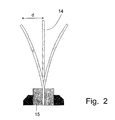
- the vibration behavior was determined by means of the measuring device shown in FIG.
- the vibrations of the free-running samples were detected as a function of time, the amplified signal supplied to a PC-Meß badge and stored with a time resolution of 4400 measurements per second as a vibration diagram.
- the envelope was determined from this oscillation diagram and the percentage residual amplitude was determined on the resulting attenuation curve 16 after 0.15 and after 0.25 seconds, respectively, compared to the output amplitude at time zero (100%).
- Fig. 4 the typical vibration behavior of conventional spring rails is shown.
- the course of the envelope or damping curve 16 follows an exponential function. This is explained by the fact that, when a leaf spring oscillates, a compressive or tensile stress occurs alternately, depending on the deflection on the blade surface. Such a vibration is usually described by a differential equation.
- the calculations of a vibration are usually based on a linear force law. This linear law of force causes the oscillation to be described very well by an exponentially decreasing oscillation curve. However, if there are magnetomechanical interactions in the microstructure, as in the case of the alloy according to the invention, the prerequisite for the linear force law is no longer met, and a mechanical hysteresis occurs during oscillation.
- a mechanical stress ⁇ in a material causes a change in the atomic distance, which in practice occurs as strain ⁇ .
- the magneto-mechanical damping is thus due to the fact that not only the change of the atomic distance (lattice strain), but also the changes caused by the stress-induced Domainwandschulen by a mechanical stress.
- the damping can be further improved by a coating with the aid of a thermosetting powder coating.
- a coating has an advantageous effect in several respects; it increases the corrosion resistance and the tensile strength and allows a favorable for the insertion of a spring rail in the wiper strip friction coefficient, and to adapt the surface texture and appearance of the appearance of the wiper strip, made of rubber.
- the reason for the excellent damping behavior of the spring elements according to the invention is the structure of soft magnetic ferrite and comparatively hard magnetic martensite with non-magnetic fine precipitates of carbides and / or carbonitrides and the volume fractions of the two magnetic phases ferrite and martensite.
- the ferrite has a high magnetic polarization, ie a very strong internal magnetization compared to the saturation magnetization of pure iron with 2.2 T or 22000 Gauss. This results in a slight remagnetization, ie the ferrite is magnetically soft, which is reflected in a low coercive force or a low wall energy.
- the martensite has a lower magnetizability or a significantly lower magnetic polarization; In comparison to ferrite, however, its magnetic domains are more strongly fixed in terms of energy due to the fine precipitates, but also due to alloying elements dissolved in the crystal lattice. Compared to ferrite, the martensite is harder to magnetize, it is therefore magnetically harder and therefore has a higher HC value.
- the magnetic domains are magnetizable areas bounded by so-called Bloch walls.
- the stability of the magnetic domains is expressed in the so-called wall energy.
- the wall energies of the ferrite are generally small and therefore cause a slight remagnetization or a low coercive force below about 1 A / cm.
- the damping behavior can be adjusted or optimized. This is done by means of a solution annealing with a duration of 0.5 to 60 min at 900 to 1100 ° C and cold working with a total deformation of more than 65%. In this way, a magnetic saturation can be achieved as the sum value for the two magnetizable phases ferrite (10 to 55%, remainder substantially martensite) and martensite in the order of 1.45 to 1.75 T.
- the cold working may be followed by annealing treatment for adjusting the magnetic hardness, for example, for 0.1 to 1 minute at a temperature of 200 to 380 ° C to obtain a coercive force of 190 to 320 A / cm.
- the tempering treatment can be done simultaneously with the coating with a thermosetting paint powder or varnish.
Landscapes
- Chemical & Material Sciences (AREA)
- Engineering & Computer Science (AREA)
- Mechanical Engineering (AREA)
- Materials Engineering (AREA)
- Metallurgy (AREA)
- Organic Chemistry (AREA)
- Physics & Mathematics (AREA)
- Thermal Sciences (AREA)
- Crystallography & Structural Chemistry (AREA)
- Heat Treatment Of Articles (AREA)
- Soft Magnetic Materials (AREA)
- Springs (AREA)
- Glass Compositions (AREA)
- Hard Magnetic Materials (AREA)
Description
- Die Erfindung bezieht sich auf ein Federelement, insbesondere auf eine Federschiene für Scheibenwischer, wie sie beispielsweise bei den üblicherweise gekrümmten Windschutzscheiben von Kraftfahrzeugen, Schienenfahrzeugen, Schiffen und Flugzeugen zur Verwendung kommen.
- Scheibenwischer bestehen üblicherweise aus einem Wischerhebel mit einem Wischerblatt aus einer Federschiene und einer Wischleiste, das mit Hilfe von Federkräften an die zu reinigende Scheibe gepreßt wird. Um die notwendige Reinigungswirkung zu erreichen, ist es erforderlich, daß die gummielastische Wischleiste unabhängig von der Scheibenkrümmung stets dicht an der Scheibenoberfläche anliegt. Dies gewährleisten zwischen dem Wischerhebel und der Wischleiste angeordnete Federelemente, insbesondere auch die Federschiene, deren Länge im wesentlichen der gummielastischen Wischleiste entspricht.
- Bei hohen Fahr- und/oder Windgeschwindigkeiten kommt es jedoch zu Turbulenzen und Schwingungen mit der Folge, daß die Wischleiste nicht über ihre gesamte Länge und/oder während ihrer gesamten Pendelbewegung gleichmäßig und mit hinreichender Anpreßkraft an der Scheibe anliegt, so daß Wasserfilme und an der Scheibe haftender Schmutz nicht zuverlässig entfernt werden.
- Moderne Scheibenwischer bestehen aus einem an einem motorisch angetriebenen Wischerhebel gelenkig angeordneten Hauptbügel, an dessen beiden Enden jeweils ein Krallenbügel gelenkig befestigt ist. Die Krallenbügel sind am einen Ende gelenkig mit einer Federschiene und am anderen Ende gelenkig mit Krallen verbunden, deren beiden Enden über Gelenke jeweils mit der Federschiene verbunden sind. Die Federschiene ist über ihre gesamte Länge in die gummielastische Wischleiste eingebettet.
- Das aus insgesamt fünf Bügeln und Federschiene bestehende Federsystem soll eine gleichmäßige Anlage der Wischleiste an der Scheibe gewährleisten. Um das zu erreichen und insbesondere Ratterschwingungen zu unterdrücken, müssen die Abstände der beiden Krallenbügel und deren Länge auf die Scheibengeometrie abgestimmt sein. Weitere Kriterien sind die Größe der zu überstreichenden Scheibenfläche, die Länge der Wischblätter, die Ausrichtung der Pendelachse des Wischerarms zur Scheibenoberfläche und insbesondere die Federkraft sowie die Breite und Dicke der Federschiene. Eine rechnerische Erfassung ist dabei kaum möglich; die Beschaffenheit der Krallenbügel und deren Positionierung in bezug auf das Wischerblatt beruhen daher zumeist auf praktischen Erfahrungen.
- Trotz aller Bemühungen gelingt es nur in Grenzen, ein Rattern und das Auftreten von Schwingungen bei hohen Fahr- und/oder Windgeschwindigkeiten zu vermeiden. Demzufolge ist das Wischergebnis unbefriedigend und kommt es zudem zu einem starken Abrieb an der Wischkante der Wischleiste sowie zu störenden Betriebsgeräuschen und zu einer Verkürzung der Lebensdauer der Wischleiste.
- Die europäische Offenlegungsschrift ,1 288 089 A2 schlägt zur Geräuschverminderung vor, den Reibungskoeffizienten einer Wischleiste mit einem speziellen Profil mit Hilfe einer Polymerbeschichtung zu verringern. Dies ist jedoch nicht nur sehr aufwendig, sondern erleichtert auch das Auftreten von Schwingungen in Folge des geringeren Reibungskoeffizienten. Des weiteren schlägt die PCT-Offenlegungsschrift WO 01/58732 A1 vor, anstelle einer einzigen, sich praktisch über die gesamte Länge der Wischleiste erstreckenden Federschiene zwei parallel zueinander verlaufender Federschienen mit unterschiedlicher Resonanzfrequenz zu verwenden, um das Auftreten von Wischerblattschwingungen zu unterdrücken. Unterschiedliche Resonanzfrequenzen erfordern jedoch hinsichtlich ihres Querschnitts und/oder ihres Werkstoffs unterschiedliche Federschienen und damit einen zusätzlichen Aufwand sowohl bei der Herstellung als auch bei der Lagerung und im Ersatzteilwesen. Hinzu kommt, daß sich das Schwingungsverhalten durch die Verwendung zweier Federschienen mit unterschiedlicher Resonanzfrequenz nur innerhalb eines verhältnismäßig engen Frequenzfensters vermeiden läßt und daher nicht alle in der Praxis auftretenden Betriebs- bzw. Schwingungszustände erfaßt.
- Als Werkstoff für Federelemente und Federschienen kommen üblicherweise legierte Stähle zur Verwendung, weil reine Kohlenstoffstähle ein geringes Dämpfungsvermögen besitzen und daher störende Schwingungen nicht rasch genug abbauen. Dies ist die Folge davon, daß im Gefüge kaum energieverzehrende Vorgänge ablaufen. Zum Beispiel, US 4 022 640 offenbart die Verwendung von Stählen aus der Reihe AISI 434, AISI 405, AISI 409, AISI 439 und AISI 431.
- Vor diesem Hintergrund besteht das der Erfindung zugrundeliegende Problem darin, das Schwingungsverhalten von Federelementen, beispielsweise das Wischverhalten von Scheibenwischern mit einer Federschiene zu verbessern.
- Dazu schlägt die Erfindung vor, als Werkstoff für Federelemente, insbesondere Federschienen einen ferritischen Chrom-Stahl mit 0,03 bis 0,12% Kohlenstoff, 0,2 bis 0,9% Silizium, 0,3 bis 1 % Mangan, 13 bis 20% Chrom, 0,1 bis 2,0% Molybdän, 0,05 bis 1,0% Kupfer, 0,02 bis 0,05% Stickstoff, unter 0,01 % Titan, 0,01 bis 0,10% Niob und 0,02 bis 0,25% Vanadium, Rest Eisen zu verwenden.
- Der Stahl kann höchstens 0,1% Kohlenstoff, höchstens 1,5% Molybdän sowie 0,1% Kupfer bis 0,5% und mindestens 0,03% Stickstoff - einzeln oder nebeneinander - enthalten.
- Besonders bewährt hat sich ein Stahl mit 0,06 bis 0,1% Kohlenstoff, 15 bis 18% Chrom und 0,8 bis 1,5% Molybdän.
- Das erfindungsgemäße Federelement besitzt eine Koerzitivkraft HC von 190 bis 240 A/cm sowie eine Sättigungsmagnetisierung Jma von 1,45 bis 1,75 T, was einem Ferritanteil im Gefüge von etwa 10% bzw. 55% entspricht.
- Diese Daten lassen sich beispielsweise dadurch erreichen, daß Kaltband oder Flachdraht aus der erfindungsgemäßen Legierung kaltverformt und anschließend lösungsgeglüht sowie an Luft abgekühlt oder mit Wasser abgeschreckt und dabei ein magnetisierbares Gefüge mit der oben erwähnten magnetischen Sättigung eingestellt wird. Mit Hilfe mindestens eines weiteren Kaltverformens läßt sich dann gegebenenfalls stufenweise die gewünschte Koerzitivkraft einstellen.
- Zur Verbesserung der mechanischen und/oder optischen Eigenschaften kann das Ausgangsmaterial oder das Federelement (Federschiene) mit einer vorzugsweise 50 bis 150 µm dicken Beschichtung aus einem Duroplast-Pulverlack versehen werden. Das Beschichten geschieht unter Wärmeeinwirkung und ist daher zwangsläufig mit einem vorteilhaften Anlassen des Werkstoffs verbunden.
- Die erfindungsgemäßen Federelemente zeichnen sich durch eine hohe Federkraft und eine hohe Witterungsbeständigkeit sowie insbesondere eine starke magnetomechanische Schwingungsdämpfung aus. Das vorteilhafte Schwingungsverhalten erlaubt den Wegfall der aufwendigen Krallen und gegebenenfalls auch des Krallenbügels, mithin einen Scheibenwischer, bei dem der Wischerarm über den Hauptbügel direkt an der Federschiene angreift.
- Das aus Ferrit und Martensit mit unmagnetischen Feinausscheidungen wie Nitriden und Karbonitriden bestehende Gefüge gewährleistet eine hohe Anfangsdämpfung, deren Ursache eine spannungsinduzierte Domänenwandung der Gefügebestandteile ist. Dabei handelt es sich um innere Änderungen der Magnetisierung wie spannungsinduzierte anelastische Domänenwandbewegungen, die zu Wirbelstromverlusten führen und dadurch Schwingungsenergie verbrauchen.
- Die Erfindung wird nachfolgend anhand von Zeichnungen in Verbindung mit Ausführungsbeispielen des näheren erläutert. Dabei zeigen:
- Fig. 1
- den Aufbau eines herkömmlichen Wischerarms,
- Fig.2
- eine Meßvorrichtung zum Bestimmen des Schwingungsverhaltens von Federschienen,
- Fig. 3
- eine grafische Darstellung des Schwingungsverhaltens herkömmlicher Federschienen,
- Fig. 4
- eine grafische Darstellung des Schwingungsverhaltens einer erfindungsgemäßen Federschiene im Vergleich zu zwei Federschienen aus herkömmlichen Stählen.
- Nach der Darstellung in Fig. 1 besteht ein herkömmlicher Scheibenwischer aus einem Wischerarm 1, dessen Ende gelenkig mit einem Hauptbügel 2 verbunden ist. An den beiden Enden des Hauptbügels ist jeweils ein Krallenbügel 3, 4 gelenkig gelagert. Die Enden 5,6 der längeren Schenkel der Krallenbügel 3, 4 greifen gelenkig an einer Federschiene 7 an, die zusammen mit einer gummielastischen Wischleiste 8 als Wischerblatt zum Entfernen von Wasser und Verschmutzungen auf einer Fahrzeugscheibe dient.
- Die kürzeren Schenkel der Krallenbügel 3, 4 sind hingegen über Gelenke 10, 11 jeweils mit einer Kralle 12, 13 verbunden, deren Enden gelenkig an der Federschiene 7 angreifen.
- Die Verwendung einer erfindungsgemäßen Federschiene erlaubt es, bei einem Scheibenwischer der dargestellten Art auf die beiden Krallenbügel 3, 4 oder auch auf die Krallen 12, 13 zu verzichten. Dadurch verringert sich der Montageaufwand für den Scheibenwischer um etwa 50%. Dies gilt unabhängig von dem Querschnittsprofil der Federschiene, deren vorteilhaftes Dämpfungsvermögen sich bei unterschiedlichen Profilen zeigt.
- Die Erfindung wird nachfolgend anhand von Ausführungsbeispielen und Vergleichslegierungen des näheren erläutert.
- Aus der nachfolgenden Tabelle 1 ergeben sich die Zusammensetzungen von fünf erfindungsgemäßen Chrom-Stählen E1 bis E5 sowie von sieben Vergleichsstählen V6 bis V12.
Tabelle I Stahl % C % Si % Mn % Cr % Ni % Mo % Cu %N E1 0,06 0,50 0,65 17,3 0,26 0,15 0;21 0,030 E2 0,07 0,52 0,48 17,0 0,32 0,14 0,15 0,045 E3 0,08 0,48 0,52 16,2 0,35 0,10 0,12 0,040 E4 0,10 0,65 0,61 17,6 0,40 0,07 0,15 0,035 E5 0,06 0,44 0,92 16,8 0,30 0,82 0,35 0,035 V6 0,03 0,58 0,49 17,1 0,32 0,10 0,12 0,040 V7 0,35 0,62 0,69 14,1 0,18 0,08 0,17 0,030 V8 0,07 0,45 0,98 18,0 6,12 0,12 0,09 0,360 V9 0,10 0,86 1,22 17,4 8,15 0,36 0,19 0,020 V10 0,47 0,25 0,55 Spuren Spuren Spuren Spuren Spuren V11 0,55 0,48 0,94 0,95 Spuren Spuren Spuren Spuren V12 0,79 0,18 0,78 Spuren Spuren Spuren Spuren Spuren - Die Stähle wurde hinsichtlich ihrer
- Zugfestigkeit Rm
- Koerzitivkraft HC
- Sättigungsmagnetisierung J
- Dämpfung als prozentuale Amplitude nach 15 Sekunden
- Dämpfung als prozentuale Amplitude nach 25 Sekunden
- Für die Herstellung einer Federschiene wurden die erfindungsgemäßen Legierungen E1 bis E6 mit einem Querschnitt von 28 mm2 im weichgeglühten Zustand eingesetzt. Nach einem ersten Kaltverformen wurden die Proben 12 Minuten einem Lösungsglühen bei 1050°C ausgesetzt, rasch abgekühlt und einer weiteren Kaltverformung bis zu einem Endquerschnitt von 6 mm2 unterzogen. Bei diesen Bearbeitungsschritten ergibt sich eine Gesamtverformung von 78%. Die Proben wurden danach zur Vorbereitung einer Beschichtungs- bzw. Anlaßbehandlung in einem Ultraschallbad gereinigt, auf 350°C erwärmt und mit einem Pulverlack beschichtet. Die Beschichtung wurde während der Abkühlphase der Anlaßbehandlung aufgebracht, um die Prozeßwärme der Federschiene für das Aushärten des Pulverlacks zu nutzen.
- Eine der Proben aus der Legierung E4 wurde vor dem vorerwähnten ersten Kaltverformen zusätzlich vorverformt, anschließend geglüht und dann so weiterbehandelt wie die anderen Proben (vgl. Versuch 8).
- Die Untersuchungsergebnisse sind in der nachfolgenden Tabelle II zusammengestellt, die ausser der Schichtdicke auch die Härtetemperatur bzw. die Beschichtungstemperatur umgibt; sie bewirkt ein Anlassen und führt zu einer Erhöhung der Zugfestigkeit, wie das Dämpfungsverhalten des Versuchs 5 zeigt, der sich auf eine Probe der Legierung E1 ohne Beschichtung und demgemäß auch ohne Anlassen beim Beschichten bezieht. Hier wird die Bedeutung des Anlassens für den Zuwachs an Festigkeit deutlich.
Tabelle II Versuch Stahl Koerzitivkraft Sättig.Magnetis. Zugfestigkeit %Restamplitude nach Beschichtung Dicke/Härtetemp. Bewertung Bewertung Nr. Hc (A/cm) J (T) Rm (MPa) 0,15 s 0,25 s min °C Festigkeit Dämpfung 1 E1 217 1,65 1682 39,0 15,0 keine 340 + gut 2 E1 216 1,67 1695 31,0 14,0 0,8 340 + gut 3 E1 219 1,52 1774 36,0 12,5 0,8 340 + sehrgut 4 E1 192 1,82 1685 54,0 35,0 0,8 340 + schlecht 5 E2 225 1,76 1851 35,0 12,0 0,8 340 + sehr gut 6 E3 215 1,72 1712 35,0 12,5 0,8 340 + sehr gut 7 E4 198 1,62 1849 34,5 10,0 0,8 340 + sehr gut 8 E4 205 1,63 1670 35,0 11,0 0,8 340 + sehr gut 9 E5 230 1,53 1716 34,0 11,0 0,8 340 + sehr gut 10 E5 232 1,55 1728 33,0 10,0 0,8 340 + sehr gut 11 V6 38 1,54 535 n.b. n.b. 0,8 340 - 12 V6 47 1,48 726 n.b. n.b. 0,8 340 - 13 V6 49 1,43 980 n.b. n.b. keine - - 14 V7 382 1,58 1682 60,0 39,0 0,8 340 + mittel 15 V8 936 0,32 1640 55,0 34,0 0,8 340 + schlecht 16 V9 914 0,36 1728 54,5 34,0 0,8 340 + schlecht 17 V9 973 0,31 1620 57,0 35,0 0,8 340 + ungenügend 18 V9 766 0,22 1452 n.b. n.b. 0,8 340 - 19 V10 123 1,83 1820 60,0 39,0 keine - + schlecht 20 V10 125 1,82 1845 59,0 38,0 0,8 340 + schlecht 21 V11 129 1,84 1960 61,0 38,0 keine - + schlecht 22 V11 131 1,91 1986 59,0 37,0 0,8 340 + schlecht 23 V12 122 1,97 2020 63,0 42,0 keine - + ungenügend 24 V12 122 1,97 2022 62,0 40,0 0,8 340 + ungenügend - Bei den Versuchen 11 bis 13 und 18 handelt es sich um Stähle, die zu weich sind und keine ausreichende Federeigenschaften besitzen. Die Bestimmung der Federdämpfung machte daher wenig Sinn. Demgemäß ist zu diesen Versuchen in der Tabelle II keine Restamplitude angegeben (n.b.).
- Generell gilt für die Restamplitude, daß die Schwingungsdämpfung um so besser ist, je geringer die angegebene Restamplitude ist.
- Das Schwingungsverhalten wurde mit Hilfe der in Fig. 3 dargestellten Meßvorrichtung bestimmt. Bei den Versuchen wurden die Proben 14 einseitig in einen Sockel 15 eingespannt, dann seitlich um eine Distanz von D = 11 mm ausgelenkt und sich sodann selbst überlassen. Mit Hilfe eines Sensors wurden die Schwingungen der freischwingenden Proben in Abhängigkeit von der Zeit erfaßt, das verstärkte Signal einer PC-Meßkarte zugeführt und mit einer zeitlichen Auflösung von 4400 Meßwerten pro Sekunde als Schwingungsdiagramm gespeichert. Von diesem Schwingungsdiagramm wurde die Einhüllende bestimmt und an der sich daraus ergebenden Hüll- bzw. Dämpfungskurve 16 nach 0,15 und nach 0,25 Sekunden jeweils die im Vergleich zur Ausgangsamplitude im Zeitpunkt Null (100%) die prozentuale Restamplitude bestimmt.
- Die Ermittlung der magnetischen Kennwerte der Proben geschah mit Hilfe einer Hysteresekurve, aus der die Werte für die Koerzitivkraft HC und die Sättigungsmagnetisierung Jmax nach DIN 50460 entnommen wurden.
- In Fig. 4 ist das typische Schwingungsverhalten herkömmlicher Federschienen dargestellt. Der Verlauf der Hüll- bzw. Dämpfungskurve 16 folgt einer exponentiellen Funktion. Dies erklärt sich daraus, dass beim Schwingen einer Blattfeder je nach Auslenkung an der Blattoberfläche abwechselnd eine Druck- oder eine Zugspannung auftritt. Eine solche Schwingung wird in der Regel durch eine Differentialgleichung beschrieben. Den Berechnungen einer Schwingung wird üblicherweise ein lineares Kraftgesetz zu Grunde gelegt. Dieses lineare Kraftgesetz bewirkt, dass die Schwingung sehr gut durch eine exponentiell abfallende Schwingungskurve beschrieben werden kann. Gibt es jedoch wie bei der erfindungsgemäßen Legierung magnetomechanische Wechselwirkungen im Gefüge, so ist die Voraussetzung für das lineare Kraftgesetz nicht mehr erfüllt, und es kommt beim Schwingen zu einer mechanischen Hysterese. Diese ist bei großen Amplituden oder Ausschlägen stärker als bei kleinen, da die Verlustenergie von der Fläche der Hysteresekurve abhängt. In einem solchen Fall wird keine exponentiell abfallende Dämpfungskurve erzielt. Vielmehr gibt es eine sehr starke Anfangsdämpfung (vgl. Hornbogen, Metallkunde, 2. Auflage).
- Ähnlich verlaufen die beiden Dämpfungskurven 17, 18 für die Federschienen aus Vergleichsstählen V9 und V10 in den Tabellen I und II; diese folgen dem Hookschen Gesetz. Anders hingegen verläuft die Kurve 19 für die erfindungsgemäße Federschiene aus dem Stahl E1 in Tabelle I bzw. dem Versuch 2 in Tabelle II. Der Verlauf der Kurve 19 zeigt aufgrund ihres verhältnismäßig steilen Abfalls eine hohe Anfangsdämpfung, die sich durch eine nichtlineare Abweichung vom Hookschen Gesetz erklären läßt und ihre Ursache in den erwähnten spannungsinduzierten Domänenwandbewegungen hat, wie sie innerhalb des erfindungsgemäßen Wertefeldes von Koerzitivkraft und magnetischer Sättigung auftritt.
- Grundsätzlich bewirkt eine mechanische Spannung σ in einem Werkstoff eine Änderung des Atomabstandes, was in der Praxis als Dehnung ε in Erscheinung tritt. Daraus leitet sich die bekannte Beziehung, bzw. der Elastizitätsmodul E ab, entsprechend:

- Im Falle magnetisch gekoppelter Gefügebestanteile wie Ferrit und Martensit bewirkt eine Spannung aber zusätzlich zur Gitterdehnung noch eine Veränderung der Domänenanordnurig, weshalb in der Gleichung eine Zusatzdehnung εMM berücksichtigt werden muß. Dadurch ergibt sich die Beziehung

- Mit εMM sind alle magnetisch induzierten Dehnungen und Zusatzdehnungen zusammengefaßt; sie setzt sich aus 3 Teildehnungen zusammen und erfaßt auch die Volumenmagnetostriktion und ihren analogen Dehnungsanteil.
- Die magneto-mechanische Dämpfung kommt somit dadurch zustande, daß durch eine mechanische Spannung nicht nur die Änderung des Atomabstandes (Gitterdehnung), sondern auch die Änderungen durch die spannungsinduzierten Domänenwandbewegungen wirksam werden.
- Das günstige Schwingungsverhalten erklärt sich durch eine starke magnetomechanische Dämpfung. Diese entsteht dadurch, daß bei einer Schwingung infolge zeitlicher Änderungen in der mechanischen Spannung die Domänenanordnungen in Form einer erzwungenen Volumenmagnetostriktion verändert werden.
- Da die spannungsinduzierte Domänenwandbewegung mit anelastischen und Wirbelstromverlusten verbunden ist, tritt bei schwingender Belastung eine mechanische Hysterese auf, d.h. eine nichtlineare Abweichung vom Hookschen Gesetz.
- Dabei spielt naturgemäß die Stärke der Hindernisse für die Domänenwandbewegungen (also die Wandenergie und damit der HC-Wert) eine große Rolle, da sie letztlich für das Ausmaß der Dämpfung verantwortlich sind. Eine optimale magnetomechanische Dämpfung durch spannungsinduzierte Domänenwandbewegungen ist demzufolge nur in einem bestimmten Wertefeld von J (magnetischer Polarisation) und HC (Koerzitivkraft) möglich.
- Die Dämpfung läßt sich durch eine Beschichtung mit Hilfe eines Duroplast-Pulverlacks weiter verbessern läßt. Eine derartige Beschichtung wirkt sich in mehrfacher Hinsicht vorteilhaft aus; sie erhöht die Korrosionsbeständigkeit sowie die Zugfestigkeit und erlaubt einen für das Einschieben einer Federschiene in die Wischleiste günstigen Reibungskoeffizienten sowie, die Oberflächenstruktur und das Aussehen dem Erscheinungsbild der Wischleiste, aus Gummi anzupassen.
- Ursächlich für das ausgezeichnete Dämpfungsverhalten der erfindungsgemäßen Federelemente (Federschiene) sind das aus weichmagnetischem Ferrit und demgegenüber verhältnismäßig hartmagnetischem Martensit mit unmagnetischen Feinausscheidungen aus Karbiden und/oder Karbonitriden bestehende Gefüge sowie die Volumenanteile der beiden magnetischen Phasen Ferrit und Martensit. Der Ferrit besitzt eine hohe magnetische Polarisation, d.h. eine sehr starke innere Magnetisierung im Vergleich zu der Sättigungsmagnetisierung von reinem Eisen mit 2,2 T bzw. 22000 Gauss. Daraus resultiert eine leichte Ummagnetisierung, d.h. der Ferrit ist magnetisch weich, was sich an einer niedrigen Koerzitivkraft bzw. einer niedrigen Wandenergie zeigt. Der Martensit besitzt zwar eine geringere Magnetisierbarkeit bzw. eine deutlich geringere magnetische Polarisation; im Vergleich zum Ferrit sind aber seine magnetischen Domänen aufgrund der Feinausscheidungen, aber auch durch im Kristallgitter gelöste Legierungselemente energetisch stärker fixiert. Im Vergleich zum Ferrit läßt sich der Martensit schwerer ummagnetisieren, er ist daher magnetisch härter und besitzt demzufolge einen höheren HC-Wert.
- Bei den magnetischen Domänen handelt es sich um magnetisierbare Bereiche, die durch sogenannte Bloch-Wände begrenzt sind. Die Stabilität der magnetischen Domänen kommt in der sogenannten Wandenergie zum Ausdruck. Die Wandenergien des Ferrits sind im allgemeinen klein und begründen daher eine leichte Ummagnetisierung bzw. eine niedrigen Koerzitivkraft unter etwa 1 A/cm.
- Mit Hilfe des Volumenanteils der beiden magnetisierbaren Gefügebestandteile Ferrit und Martensit (vorzugsweise 30% Ferrit, Rest Martensit einschließlich geringfügiger nicht magnetischer Ausscheidungen) sowie der dadurch bedingten magnetischen Härte läßt sich das Dämpfungsverhalten einstellen bzw. optimieren. Dies geschieht mit Hilfe eines Lösungsglühens mit einer Dauer von 0,5 bis 60 min bei 900 bis 1100 °C und eines Kaltverformens mit einem Gesamtverformungsgrad von über 65%. Auf diese Weise läßt sich eine magnetische Sättigung als Summenwert für die beiden magnetisierbaren Phasen Ferrit (10 bis 55%, Rest im wesentlichen Martensit) und Martensit in der Größenordnung von 1,45 bis 1,75 T erreichen.
- Dem Kaltverformen kann sich zum Einstellen der magnetischen Härte eine Anlaßbehandlung anschließen, beispielsweise mit einer Dauer von 0,1 bis 1 min bei einer Temperatur von 200 bis 380 °C, um eine Koerzitivkraft von 190 bis 320 A/cm zu erreichen. Die Anlassbehandlung kann gleichzeitig mit dem Beschichten mit einem warmaushärtenden Lackpulver bzw. Lack geschehen.
Claims (10)
- Federelement, insbesondere Federschiene für Scheibenwischer aus einem ferritischen Chrom-Stahl, bestehend aus
0,03 bis 0,12% Kohlenstoff 0,2 bis 0,9% Silizium 0,3 bis 1 % Mangan 13 bis 20% Chrom unter 0,5% Nickel 0,1 bis 2% Molybdän 0,05 bis 1,0% Kupfer 0,02 bis 0,05% Stickstoff unter 0,01 % Titan 0,01 bis 0,10% Niob 0,02 bis 0,25% Vanadium, Rest Eisen. - Federelement nach Anspruch 1, dadurch gekennzeichnet, daß der Stahl höchstens 0,1% Kohlenstoff, höchstens 1,5% Molybdän, 0,1 bis 0,5% Kupfer und mindestens 0,03% Stickstoff enthält.
- Federelement nach Anspruch 1, gekennzeichnet durch einen Kohlenstoffgehalt von 0,06 bis 0,1%, einen Chromgehalt von 15 bis 18% und einen Molybdängehalt von 0,8 bis 1,5%.
- Federelement nach einem der Ansprüche 1 bis 3, gekennzeichnet durch eine Koerzitivkraft von 190 bis 320 A/cm und eine magnetische Sättigung von 1,45 bis 1,75 T.
- Federelement nach einem der Ansprüche 1 bis 4, gekennzeichnet durch eine Pulverlack-Beschichtung aus Duroplast.
- Federelement nach Anspruch 5, gekennzeichnet durch eine Schichtdicke von 0,05 bis 0,15 mm.
- Federelement nach einem der Ansprüche 1 bis 6, gekennzeichnet durch ein Lösungsglühen von 0,5 bis 60 min bei 900 bis 1100 °C.
- Federelement nach Anspruch 7, gekennzeichnet durch ein Kaltverformen mit einem Verformungsgrad von über 65%.
- Federelement nach Anspruch 8, gekennzeichnet durch ein Anlassen nach dem Kaltverformen von 0,1 bis 1 min bei 200 bis 380 °C.
- Federelement nach Anspruch 9, gekennzeichnet durch eine Aushärtungstemperatur der Beschichtung im Bereich der Anlaßtemperatur.
Applications Claiming Priority (5)
| Application Number | Priority Date | Filing Date | Title |
|---|---|---|---|
| DE10237446 | 2002-08-16 | ||
| DE10237446A DE10237446B4 (de) | 2002-08-16 | 2002-08-16 | Verwendung eines Chrom-Stahls und dessen Herstellung |
| DE2003133272 DE10333272A1 (de) | 2003-07-21 | 2003-07-21 | Federelement aus einem ferritischen Chrom-Stahl |
| DE10333272 | 2003-07-21 | ||
| PCT/EP2003/009132 WO2004018271A1 (de) | 2002-08-16 | 2003-08-18 | Federelement aus einem ferritischen chrom-stahl |
Publications (2)
| Publication Number | Publication Date |
|---|---|
| EP1528995A1 EP1528995A1 (de) | 2005-05-11 |
| EP1528995B1 true EP1528995B1 (de) | 2006-07-05 |
Family
ID=31947608
Family Applications (1)
| Application Number | Title | Priority Date | Filing Date |
|---|---|---|---|
| EP03792362A Expired - Lifetime EP1528995B1 (de) | 2002-08-16 | 2003-08-18 | Federelement aus einem ferritischen chrom-stahl |
Country Status (9)
| Country | Link |
|---|---|
| US (2) | US20050279434A1 (de) |
| EP (1) | EP1528995B1 (de) |
| JP (1) | JP2005538247A (de) |
| KR (1) | KR100970149B1 (de) |
| AU (1) | AU2003255455A1 (de) |
| DE (1) | DE50304152D1 (de) |
| ES (1) | ES2242553T3 (de) |
| PL (1) | PL200872B1 (de) |
| WO (1) | WO2004018271A1 (de) |
Families Citing this family (9)
| Publication number | Priority date | Publication date | Assignee | Title |
|---|---|---|---|---|
| EP1627786B1 (de) * | 2004-08-20 | 2007-09-19 | Federal-Mogul S.A. | Scheibenwischervorrichtung |
| KR100676470B1 (ko) | 2006-03-31 | 2007-02-02 | 고려제강 주식회사 | 와이퍼 블레이드용 탄성지지대 |
| KR100676957B1 (ko) | 2006-04-05 | 2007-02-02 | 고려제강 주식회사 | 플랫형 와이퍼 블레이드 |
| US8428819B2 (en) * | 2007-08-31 | 2013-04-23 | GM Global Technology Operations LLC | Suspension system with optimized damper response for wide range of events |
| DE102008014938B9 (de) | 2008-02-29 | 2015-10-29 | Stahlwerk Ergste Westig Gmbh | Verfahren zum Herstellen von Federschienen für Scheibenwischer |
| JP5550405B2 (ja) * | 2010-03-23 | 2014-07-16 | 中央発條株式会社 | ばねの製造方法 |
| DE102012009496B4 (de) * | 2012-05-14 | 2017-05-11 | Stahlwerk Ergste Westig Gmbh | Chromstahl |
| KR101607546B1 (ko) * | 2014-12-04 | 2016-03-31 | 주식회사 포스코 | 건축 자재 |
| US10899187B2 (en) * | 2018-11-19 | 2021-01-26 | Anatoliy Alekseevich Kuznetsov | Method of making automotive leaf springs |
Family Cites Families (20)
| Publication number | Priority date | Publication date | Assignee | Title |
|---|---|---|---|---|
| US257521A (en) * | 1882-05-09 | Stencil-printing machine | ||
| US2527521A (en) * | 1947-01-10 | 1950-10-31 | Armco Steel Corp | Spring and method |
| US4022640A (en) * | 1974-01-18 | 1977-05-10 | Armco Steel Corporation | Process for cold-working and stress-relieving non-heat hardenable ferritic stainless steels |
| JPS60213246A (ja) | 1984-04-05 | 1985-10-25 | Satoru Baba | モ−タ−の整流子用ブラシ及びその製造法 |
| JP2756549B2 (ja) * | 1989-07-22 | 1998-05-25 | 日新製鋼株式会社 | ばね特性に優れた高強度複相組織ステンレス鋼帯の製造法 |
| JPH04154921A (ja) | 1990-10-16 | 1992-05-27 | Nisshin Steel Co Ltd | 形状の優れた高強度ステンレス鋼帯の製造方法 |
| DE4301754C2 (de) * | 1993-01-23 | 1994-10-20 | Rexnord Kette Gmbh & Co Kg | Verfahren zum Herstellen von warmgewalztem Stahlband mit eingestellter Festigkeit |
| US6544356B2 (en) * | 1996-12-05 | 2003-04-08 | Nisshin Steel Co., Ltd. | Steel sheet for use as an electrode-supporting frame member of a color picture tube and manufacturing method thereof |
| JP3839953B2 (ja) | 1998-04-17 | 2006-11-01 | 新日本製鐵株式会社 | 建築構造用ステンレス鋼帯の製造方法 |
| EP0974676A3 (de) * | 1998-07-20 | 2003-06-04 | Firma Muhr und Bender | Verfahren zur thermomechanischen Behandlung von Stahl für torsionsbeanspruchte Federelemente |
| USRE40950E1 (en) | 1999-03-30 | 2009-11-10 | Jfe Steel Corporation | Ferritic stainless steel plate |
| US6413332B1 (en) | 1999-09-09 | 2002-07-02 | Kawasaki Steel Corporation | Method of producing ferritic Cr-containing steel sheet having excellent ductility, formability, and anti-ridging properties |
| JP2001107195A (ja) | 1999-10-01 | 2001-04-17 | Daido Steel Co Ltd | 低炭素高硬度・高耐食マルテンサイト系ステンレス鋼およびその製造方法 |
| JP3606135B2 (ja) | 1999-10-22 | 2005-01-05 | 住友金属工業株式会社 | ばね用フェライト系ステンレス鋼板とその製造方法 |
| TW480288B (en) | 1999-12-03 | 2002-03-21 | Kawasaki Steel Co | Ferritic stainless steel plate and method |
| JP4342061B2 (ja) * | 1999-12-24 | 2009-10-14 | 新日鐵住金ステンレス株式会社 | フレーム用フェライト系ステンレス鋼材およびその製造方法 |
| DE10005418A1 (de) | 2000-02-08 | 2001-08-09 | Bosch Gmbh Robert | Wischblatt für Scheiben insbesondere von Kraftfahrzeugen und Verfahren zum Herstellen des Wischblatts |
| KR200195675Y1 (ko) * | 2000-04-27 | 2000-09-01 | 강동훈 | 와이퍼 블레이드 |
| DE10113657A1 (de) * | 2001-03-21 | 2002-09-26 | Bosch Gmbh Robert | Wischblatt zum Reinigen von Scheiben, insbesondere von Kraftfahrzeugen und Verfahren zum Herstellen des Wischblatts |
| SE519777C2 (sv) | 2001-08-29 | 2003-04-08 | Nat Gummi Ab | Torkarblad och sätt för dess framställning |
-
2003
- 2003-08-18 US US10/524,719 patent/US20050279434A1/en not_active Abandoned
- 2003-08-18 EP EP03792362A patent/EP1528995B1/de not_active Expired - Lifetime
- 2003-08-18 JP JP2004530190A patent/JP2005538247A/ja active Pending
- 2003-08-18 PL PL373250A patent/PL200872B1/pl unknown
- 2003-08-18 AU AU2003255455A patent/AU2003255455A1/en not_active Abandoned
- 2003-08-18 WO PCT/EP2003/009132 patent/WO2004018271A1/de not_active Ceased
- 2003-08-18 KR KR1020057001231A patent/KR100970149B1/ko not_active Expired - Fee Related
- 2003-08-18 DE DE50304152T patent/DE50304152D1/de not_active Expired - Lifetime
- 2003-08-18 ES ES03792362T patent/ES2242553T3/es not_active Expired - Lifetime
-
2010
- 2010-02-04 US US12/700,198 patent/US8007602B2/en not_active Expired - Fee Related
Also Published As
| Publication number | Publication date |
|---|---|
| AU2003255455A1 (en) | 2004-03-11 |
| US8007602B2 (en) | 2011-08-30 |
| KR100970149B1 (ko) | 2010-07-14 |
| DE50304152D1 (de) | 2006-08-17 |
| JP2005538247A (ja) | 2005-12-15 |
| PL200872B1 (pl) | 2009-02-27 |
| US20050279434A1 (en) | 2005-12-22 |
| US20100132846A1 (en) | 2010-06-03 |
| KR20050042467A (ko) | 2005-05-09 |
| WO2004018271A1 (de) | 2004-03-04 |
| ES2242553T3 (es) | 2007-03-16 |
| ES2242553T1 (es) | 2005-11-16 |
| EP1528995A1 (de) | 2005-05-11 |
| PL373250A1 (en) | 2005-08-22 |
Similar Documents
| Publication | Publication Date | Title |
|---|---|---|
| US8007602B2 (en) | Spring element made from a ferritic chromium steel | |
| EP1905857B1 (de) | Hochfester Stahl und Verwendungen eines solchen Stahls | |
| EP3535431B1 (de) | Mittelmanganstahlprodukt zum tieftemperatureinsatz und verfahren zu seiner herstellung | |
| DE60026746T2 (de) | Treibriemen | |
| EP4388140B1 (de) | Stahl mit verbesserten verarbeitungseigenschaften zur umformung bei erhöhten temperaturen | |
| EP2905348A1 (de) | Hochfestes Stahlflachprodukt mit bainitisch-martensitischem Gefüge und Verfahren zur Herstellung eines solchen Stahlflachprodukts | |
| DE112017002175B4 (de) | Schutzstahlblech mit leistungsstarken Kaltbiegeeigenschaften und dessen Fertigungsverfahren | |
| EP4324950A1 (de) | Stahl mit verbesserten verarbeitungseigenschaften zur umformung bei erhöhten temperaturen | |
| DE69427002T2 (de) | Kaltgewalztes stahlblech mit hervorragender verzögerter bruchfestigkeit und höchster festigkeit und dessen herstellung | |
| EP1472383B1 (de) | Ausscheidungshärtbarer austenitischer stahl | |
| DE69330600T2 (de) | Federstahldrähte und Verfahren für ihre Herstellung | |
| EP0957181B1 (de) | Stahllegierung für Gleitelemente | |
| EP4174207A1 (de) | Stahlflachprodukt mit verbesserten verarbeitungseigenschaften | |
| EP4388141B1 (de) | Stahl mit verbesserten verarbeitungseigenschaften zur umformung bei erhöhten temperaturen | |
| DE102023116669A1 (de) | Seitenaufprallträger zur Verstärkung einer Fahrzeugtür | |
| DE112008001181B4 (de) | Verwendung einer Stahllegierung für Achsrohre sowie Achsrohr | |
| DE10333272A1 (de) | Federelement aus einem ferritischen Chrom-Stahl | |
| DE10237446B4 (de) | Verwendung eines Chrom-Stahls und dessen Herstellung | |
| EP4047105A1 (de) | Warmgewalztes stahlflachprodukt und verfahren zur herstellung eines warmgewalzten stahlflachprodukts | |
| DE102022132918A1 (de) | Blechformteil mit verbessertem Härteverlauf | |
| DE2923532B1 (de) | Verwendung eines ferritischen rostfreien Stahls fuer in geschweisstem Zustand ohne Waermenachbehandlung gegen interkristalline Korrosion bestaendige Gegenstaende | |
| DE69611950T2 (de) | Verfahren zur Herstellung von warmgewalztem Stahlblech mit sehr hoher Elastizitätsgrenze und Stahlblech | |
| DE68922200T2 (de) | Formbare dünne Stahlbleche und Verfahren zum Herstellen derselben. | |
| DE69302950T2 (de) | Verfahren zur Herstellung von Stahlblechen und Stahlbleche, nach diesem Verfahren hergestellt | |
| DE102024111068A1 (de) | Warmgewalztes Stahlflachprodukt und Verfahren zur Herstellung eines derartigen Stahlflachprodukts |
Legal Events
| Date | Code | Title | Description |
|---|---|---|---|
| PUAI | Public reference made under article 153(3) epc to a published international application that has entered the european phase |
Free format text: ORIGINAL CODE: 0009012 |
|
| 17P | Request for examination filed |
Effective date: 20050103 |
|
| AK | Designated contracting states |
Kind code of ref document: A1 Designated state(s): AT BE BG CH CY CZ DE DK EE ES FI FR GB GR HU IE IT LI LU MC NL PT RO SE SI SK TR |
|
| AX | Request for extension of the european patent |
Extension state: AL LT LV MK |
|
| GBC | Gb: translation of claims filed (gb section 78(7)/1977) | ||
| EL | Fr: translation of claims filed | ||
| DAX | Request for extension of the european patent (deleted) | ||
| RBV | Designated contracting states (corrected) |
Designated state(s): BE DE ES FR GB |
|
| GRAP | Despatch of communication of intention to grant a patent |
Free format text: ORIGINAL CODE: EPIDOSNIGR1 |
|
| GRAC | Information related to communication of intention to grant a patent modified |
Free format text: ORIGINAL CODE: EPIDOSCIGR1 |
|
| GRAS | Grant fee paid |
Free format text: ORIGINAL CODE: EPIDOSNIGR3 |
|
| GRAA | (expected) grant |
Free format text: ORIGINAL CODE: 0009210 |
|
| AK | Designated contracting states |
Kind code of ref document: B1 Designated state(s): BE DE ES FR GB |
|
| PG25 | Lapsed in a contracting state [announced via postgrant information from national office to epo] |
Ref country code: GB Free format text: LAPSE BECAUSE OF FAILURE TO SUBMIT A TRANSLATION OF THE DESCRIPTION OR TO PAY THE FEE WITHIN THE PRESCRIBED TIME-LIMIT Effective date: 20060705 |
|
| REG | Reference to a national code |
Ref country code: GB Ref legal event code: FG4D Free format text: NOT ENGLISH |
|
| REF | Corresponds to: |
Ref document number: 50304152 Country of ref document: DE Date of ref document: 20060817 Kind code of ref document: P |
|
| PG25 | Lapsed in a contracting state [announced via postgrant information from national office to epo] |
Ref country code: BE Free format text: LAPSE BECAUSE OF NON-PAYMENT OF DUE FEES Effective date: 20060831 |
|
| GBV | Gb: ep patent (uk) treated as always having been void in accordance with gb section 77(7)/1977 [no translation filed] |
Effective date: 20060705 |
|
| ET | Fr: translation filed | ||
| REG | Reference to a national code |
Ref country code: ES Ref legal event code: FG2A Ref document number: 2242553 Country of ref document: ES Kind code of ref document: T3 |
|
| PLBE | No opposition filed within time limit |
Free format text: ORIGINAL CODE: 0009261 |
|
| STAA | Information on the status of an ep patent application or granted ep patent |
Free format text: STATUS: NO OPPOSITION FILED WITHIN TIME LIMIT |
|
| 26N | No opposition filed |
Effective date: 20070410 |
|
| BERE | Be: lapsed |
Owner name: STAHLWERK ERGSTE WESTIG G.M.B.H. Effective date: 20060831 |
|
| REG | Reference to a national code |
Ref country code: FR Ref legal event code: PLFP Year of fee payment: 14 |
|
| PGFP | Annual fee paid to national office [announced via postgrant information from national office to epo] |
Ref country code: DE Payment date: 20160823 Year of fee payment: 14 |
|
| PGFP | Annual fee paid to national office [announced via postgrant information from national office to epo] |
Ref country code: FR Payment date: 20160825 Year of fee payment: 14 |
|
| PGFP | Annual fee paid to national office [announced via postgrant information from national office to epo] |
Ref country code: ES Payment date: 20160829 Year of fee payment: 14 |
|
| REG | Reference to a national code |
Ref country code: DE Ref legal event code: R119 Ref document number: 50304152 Country of ref document: DE |
|
| REG | Reference to a national code |
Ref country code: FR Ref legal event code: ST Effective date: 20180430 |
|
| PG25 | Lapsed in a contracting state [announced via postgrant information from national office to epo] |
Ref country code: DE Free format text: LAPSE BECAUSE OF NON-PAYMENT OF DUE FEES Effective date: 20180301 |
|
| PG25 | Lapsed in a contracting state [announced via postgrant information from national office to epo] |
Ref country code: FR Free format text: LAPSE BECAUSE OF NON-PAYMENT OF DUE FEES Effective date: 20170831 |
|
| REG | Reference to a national code |
Ref country code: ES Ref legal event code: FD2A Effective date: 20181029 |
|
| PG25 | Lapsed in a contracting state [announced via postgrant information from national office to epo] |
Ref country code: ES Free format text: LAPSE BECAUSE OF NON-PAYMENT OF DUE FEES Effective date: 20170819 |