EP1528905B1 - Patient temperature control system - Google Patents
Patient temperature control system Download PDFInfo
- Publication number
- EP1528905B1 EP1528905B1 EP03784850.4A EP03784850A EP1528905B1 EP 1528905 B1 EP1528905 B1 EP 1528905B1 EP 03784850 A EP03784850 A EP 03784850A EP 1528905 B1 EP1528905 B1 EP 1528905B1
- Authority
- EP
- European Patent Office
- Prior art keywords
- connector
- male
- female
- arm
- engagement
- Prior art date
- Legal status (The legal status is an assumption and is not a legal conclusion. Google has not performed a legal analysis and makes no representation as to the accuracy of the status listed.)
- Expired - Lifetime
Links
- 239000012530 fluid Substances 0.000 claims description 60
- 238000003780 insertion Methods 0.000 claims description 34
- 230000037431 insertion Effects 0.000 claims description 34
- 239000000463 material Substances 0.000 claims description 4
- 230000006835 compression Effects 0.000 claims description 2
- 238000007906 compression Methods 0.000 claims description 2
- 238000001816 cooling Methods 0.000 description 8
- 238000010438 heat treatment Methods 0.000 description 6
- 238000004891 communication Methods 0.000 description 5
- 230000000712 assembly Effects 0.000 description 3
- 238000000429 assembly Methods 0.000 description 3
- 210000004907 gland Anatomy 0.000 description 3
- 230000001965 increasing effect Effects 0.000 description 3
- 238000007789 sealing Methods 0.000 description 3
- 208000006011 Stroke Diseases 0.000 description 2
- 230000008901 benefit Effects 0.000 description 2
- 230000033228 biological regulation Effects 0.000 description 2
- 230000000694 effects Effects 0.000 description 2
- 210000005224 forefinger Anatomy 0.000 description 2
- 238000007726 management method Methods 0.000 description 2
- 238000000034 method Methods 0.000 description 2
- 238000012986 modification Methods 0.000 description 2
- 230000004048 modification Effects 0.000 description 2
- 210000003813 thumb Anatomy 0.000 description 2
- XLYOFNOQVPJJNP-UHFFFAOYSA-N water Substances O XLYOFNOQVPJJNP-UHFFFAOYSA-N 0.000 description 2
- 206010019196 Head injury Diseases 0.000 description 1
- 230000036760 body temperature Effects 0.000 description 1
- 230000002612 cardiopulmonary effect Effects 0.000 description 1
- 239000002131 composite material Substances 0.000 description 1
- 239000012809 cooling fluid Substances 0.000 description 1
- 238000013461 design Methods 0.000 description 1
- 230000002708 enhancing effect Effects 0.000 description 1
- 230000002452 interceptive effect Effects 0.000 description 1
- 230000013011 mating Effects 0.000 description 1
- 238000012544 monitoring process Methods 0.000 description 1
- 230000000926 neurological effect Effects 0.000 description 1
- 230000004112 neuroprotection Effects 0.000 description 1
- 238000012545 processing Methods 0.000 description 1
- 238000005096 rolling process Methods 0.000 description 1
- 238000001356 surgical procedure Methods 0.000 description 1
- 238000002560 therapeutic procedure Methods 0.000 description 1
- 238000010792 warming Methods 0.000 description 1
Images


Classifications
-
- A—HUMAN NECESSITIES
- A61—MEDICAL OR VETERINARY SCIENCE; HYGIENE
- A61F—FILTERS IMPLANTABLE INTO BLOOD VESSELS; PROSTHESES; DEVICES PROVIDING PATENCY TO, OR PREVENTING COLLAPSING OF, TUBULAR STRUCTURES OF THE BODY, e.g. STENTS; ORTHOPAEDIC, NURSING OR CONTRACEPTIVE DEVICES; FOMENTATION; TREATMENT OR PROTECTION OF EYES OR EARS; BANDAGES, DRESSINGS OR ABSORBENT PADS; FIRST-AID KITS
- A61F7/00—Heating or cooling appliances for medical or therapeutic treatment of the human body
- A61F7/02—Compresses or poultices for effecting heating or cooling
-
- A—HUMAN NECESSITIES
- A61—MEDICAL OR VETERINARY SCIENCE; HYGIENE
- A61M—DEVICES FOR INTRODUCING MEDIA INTO, OR ONTO, THE BODY; DEVICES FOR TRANSDUCING BODY MEDIA OR FOR TAKING MEDIA FROM THE BODY; DEVICES FOR PRODUCING OR ENDING SLEEP OR STUPOR
- A61M39/00—Tubes, tube connectors, tube couplings, valves, access sites or the like, specially adapted for medical use
- A61M39/10—Tube connectors; Tube couplings
-
- F—MECHANICAL ENGINEERING; LIGHTING; HEATING; WEAPONS; BLASTING
- F16—ENGINEERING ELEMENTS AND UNITS; GENERAL MEASURES FOR PRODUCING AND MAINTAINING EFFECTIVE FUNCTIONING OF MACHINES OR INSTALLATIONS; THERMAL INSULATION IN GENERAL
- F16L—PIPES; JOINTS OR FITTINGS FOR PIPES; SUPPORTS FOR PIPES, CABLES OR PROTECTIVE TUBING; MEANS FOR THERMAL INSULATION IN GENERAL
- F16L37/00—Couplings of the quick-acting type
- F16L37/08—Couplings of the quick-acting type in which the connection between abutting or axially overlapping ends is maintained by locking members
- F16L37/084—Couplings of the quick-acting type in which the connection between abutting or axially overlapping ends is maintained by locking members combined with automatic locking
- F16L37/098—Couplings of the quick-acting type in which the connection between abutting or axially overlapping ends is maintained by locking members combined with automatic locking by means of flexible hooks
- F16L37/0985—Couplings of the quick-acting type in which the connection between abutting or axially overlapping ends is maintained by locking members combined with automatic locking by means of flexible hooks the flexible hook extending radially inwardly from an outer part and engaging a bead, recess or the like on an inner part
-
- F—MECHANICAL ENGINEERING; LIGHTING; HEATING; WEAPONS; BLASTING
- F16—ENGINEERING ELEMENTS AND UNITS; GENERAL MEASURES FOR PRODUCING AND MAINTAINING EFFECTIVE FUNCTIONING OF MACHINES OR INSTALLATIONS; THERMAL INSULATION IN GENERAL
- F16L—PIPES; JOINTS OR FITTINGS FOR PIPES; SUPPORTS FOR PIPES, CABLES OR PROTECTIVE TUBING; MEANS FOR THERMAL INSULATION IN GENERAL
- F16L37/00—Couplings of the quick-acting type
- F16L37/56—Couplings of the quick-acting type for double-walled or multi-channel pipes or pipe assemblies
-
- A—HUMAN NECESSITIES
- A61—MEDICAL OR VETERINARY SCIENCE; HYGIENE
- A61B—DIAGNOSIS; SURGERY; IDENTIFICATION
- A61B17/00—Surgical instruments, devices or methods
- A61B2017/00477—Coupling
-
- A—HUMAN NECESSITIES
- A61—MEDICAL OR VETERINARY SCIENCE; HYGIENE
- A61F—FILTERS IMPLANTABLE INTO BLOOD VESSELS; PROSTHESES; DEVICES PROVIDING PATENCY TO, OR PREVENTING COLLAPSING OF, TUBULAR STRUCTURES OF THE BODY, e.g. STENTS; ORTHOPAEDIC, NURSING OR CONTRACEPTIVE DEVICES; FOMENTATION; TREATMENT OR PROTECTION OF EYES OR EARS; BANDAGES, DRESSINGS OR ABSORBENT PADS; FIRST-AID KITS
- A61F7/00—Heating or cooling appliances for medical or therapeutic treatment of the human body
- A61F2007/0054—Heating or cooling appliances for medical or therapeutic treatment of the human body with a closed fluid circuit, e.g. hot water
-
- Y—GENERAL TAGGING OF NEW TECHNOLOGICAL DEVELOPMENTS; GENERAL TAGGING OF CROSS-SECTIONAL TECHNOLOGIES SPANNING OVER SEVERAL SECTIONS OF THE IPC; TECHNICAL SUBJECTS COVERED BY FORMER USPC CROSS-REFERENCE ART COLLECTIONS [XRACs] AND DIGESTS
- Y10—TECHNICAL SUBJECTS COVERED BY FORMER USPC
- Y10T—TECHNICAL SUBJECTS COVERED BY FORMER US CLASSIFICATION
- Y10T137/00—Fluid handling
- Y10T137/8593—Systems
- Y10T137/87153—Plural noncommunicating flow paths
Definitions
- the invention described herein relates to systems for use in patient temperature control, and more specifically to devices employable for interconnecting a temperature control device such as a heating/cooling pad to a medical fluid processing apparatus.
- contact pad system for selectively cooling and/or heating bodily tissue.
- a fluid e.g. water or air
- a fluid e.g. water or air
- pads to affect surface to surface thermal energy exchange with a patient.
- U.S. Patent No. 6,197,045 One highly effective contact pad and related system is disclosed in U.S. Patent No. 6,197,045 .
- the ability to establish and maintain intimate pad to patient contact is often key importance to fully realizing medical efficacies with contact pad systems.
- Temperature management or thermal regulation can be viewed in two different ways.
- the first aspect of temperature management includes treating at normal body temperature (i.e. cooling the body for elevated temperatures or warming the body for lower temperature).
- the second aspect of thermal regulation is an evolving treatment that employs techniques that physically control a patient's temperature to provide a physiological benefit, such as cooling a stroke patient to gain some degree of neuro protection.
- cooling pad systems may be utilized in early therapy to reduce neurological damage incurred by stroke and head trauma patients. Additional applications include selected patient heating/cooling during surgical procedure such as cardio pulmonary bypass operation.
- the present inventors have recognized the desirability of enhancing the flexibility and portability of thermal exchange fluid systems. More particularly, while heating/cooling contact pads systems have proven effective for many applications, the present inventors have recognized that additional performance and potential applications can be realized via implementation of further improved hose and connector device assemblies.
- the US Patent 4,691,762 discloses a patient temperature control including a fluid circulating system comprising a male connector and a female connector configured to receive and engage the insertion end of the male connector so as to create two fluid paths connectors when engaged; said male and female connectors further including an orientation means.
- the US Patent 4,969,879 discloses a flex arm and a latch arm attached at an end of the flex arm to engage a female connector to a male connector to form a fluid channel.
- the US Patent 5,323,808 discloses a double channel male-female connector with an engagement latch arm and including plug and receptacle valves in the connectors.
- the object of the present invention is to provide the male-female connector arrangement of the fluid circulating system in a patient temperature control system that is easy to manipulate while improving the reliability in terms of a seal and interconnection therebetween.
- a system employable for patient temperature control including a fluid circulating system including at least one reservoir for circulating a fluid, as defined in the appended claims.
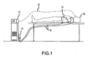
- Fig. 1 Disclosed in Fig. 1 is an exemplary configuration of the temperature control system which is employable to provide heating/cooling of a patient 20.
- pads 18 positionable on a patient 20 may be of the type described in U.S. Patent No. 6,197,405 .
- the system 10 is employable for circulating temperature control fluid through the pad 18.
- the system 10 may include a circulating pump for drawing fluid (e.g. water) through the pads, a circulating reservoir as well as one or more heat exchange devices for heating/cooling fluid circulating through the system. Also included may a temperature sensor 22 employable for monitoring patient temperature.
- fluid e.g. water
- a temperature sensor 22 employable for monitoring patient temperature.
- hose and connector assembly 14 Interconnecting the patient temperature control system 10 and the pads 18 is hose and connector assembly 14. Included in the assembly 14 may be one or more individual connectors, as well as lengths of hose 16 which act as delivery and return lines for the fluid circulated between system 10 and pads 18.
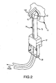
- Fig. 2 Disclosed in Fig. 2 is a view of the hose and connector assembly 14 interconnected with system 10, specifically including the various connectors which may be employed in order to connect the patient temperature control system 10 to the patient temperature control pad(s).
- Shown in particular is female machine connector 12 which provides for the attachment of the hose assembly 14 to the control system 10.
- the connector 12 may be incorporated into system 10 and be in fluid communication with the various reservoirs and heat exchange devices included therein.
- the system connector 12 may include at least one receiving end for receiving a male connector portion of the hose and connector assembly 14.
- the system connector may includes a connection device 108 which is manipulable to establish a fluid tight connection.
- connection device 108 which is manipulable to establish a fluid tight connection.
- the hose assembly 14 may include a male machine connector 13 configured to be insertable within the female machine connector and be engaged.
- the connector 13 may be attached to one-piece hose apparatus 15 which is further in connection with female intermediate connector 19.
- the female intermediate connector 19 may include one or more receiving ends configured to receive and engage any number male intermediate connectors 30.
- the male intermediate connectors are further connectable through hoses to 16 the patient temperature control pads.
- the connection to the patient temperature control pads may be through a single length of hose or through various lengths of hose interconnected using one or more male and female intermediate connector combinations.
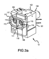
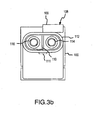
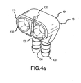
- Figs. 3a and b are perspective and front views of female machine connector 12 which is mountable within the housing for temperature control system 10.
- a receiving end 112 specially configured for receiving a insertion end of a male connector.
- a wall structure 106 extending outward from the body 101 of connector 12.
- a cavity 113 which includes a cross section sized to fit with the insertion end of a male connector at a substantially close tolerance.
- openings for fluid channels 115 and 117 which extend above the floor of the cavity 113 and where each include at least one gasket device 116 for establishing a fluid tight seal.
- the fluid channels 115 and 117 pass through the female connector 12 and exit through channels 104 and 102 respectively. When installed in the temperature control system 10, these channels provide for the circulation of fluid to and from internal components of the system.
- a rotational engagement device 108 which is configured to pass within an engagement portion of a male connector, and upon rotation mechanically engage said male connector.
- engagement shaft 110 which in the configuration of the invention shown in Fig. 2a is configured with a cross sectional shape of a semi-circle.
- the use of a semi-circle is exemplary, and any number other cross sectional shapes may be employable for this purpose.
- the rotatable engagement device 108 further includes a retaining end 111 which passes through the wall portion of the cavity 113 and supports the engagement shaft at one end.
- the rotatable handle 108 At the opposite end of the engagement shaft is the rotatable handle 108 which is rotatable to provide for the rotation of the engagement shaft 110.
- the handle portion 108 further includes retaining end portion which also passes within the wall structure 110. At either end of the shaft, the hole through the wall provides a bearing surface for rotation of the shaft.
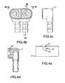
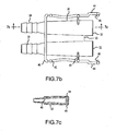
- Fig. 4a Disclosed in Fig. 4a is a geometric view of the male machine connector 13 employable to interconnect with female machine connector 12.
- the connector includes a body portion 121 through which two fluid channels 130 and 132 extend from insertion end 119 to attachment portions 134 and 136, respectively.
- the insertion end 119 disclosed herein is configured in a oval and/or race track type shape, although one skilled in the art would realize that any number of shapes are employable.
- the fluid channels are configured to turn at substantially a 90° angle, however one skilled in the art would realize that any number of configurations are possible.
- the interior surface fluid channels 130 and 132 are configured with a tapering cross section shape so that a fluid type seal may be created when the surfaces contact the fluid channels 115 and 117 in female connector 12.
- Attachment ends 134 and 136 may be configured to each attach to a hose for employable for circulating fluid to a remote device such as a temperature control pad. This configuration is especially applicable to connecting two lengths of hose between the system 10 and the patient temperature control pads without the use of any intermediate connectors.
- the connector ends may be replaced by a one-piece structure connectable to the body portion, where the one-piece structure includes a plurality of fluid channels passing therethrough. The one-piece structure may be further connectable to an intermediate connector. This configuration, including all its components, will be discussed in greater detail below.
- At least one engagement portion 120 specially configured to receive and mechanically engage with the engagement shaft of the female connector.
- a view of the engagement portion 120 can be seen in the top view of the male connector in Fig. 4e .
- the engagement portion includes a narrow, substantially rectangular slot 121 which opens up into a larger substantially circular area 123.
- This configuration allows the engagement shaft to pass within the smaller slot 121 at a first rotational orientation and then once within the cylindrical area 123, rotate to a second rotational position whereby the relative width of the shaft is greater than the slot. At this second orientation, shaft contacts a portion of the interior surface of the circular area such that the male and female connectors are mechanically engaged.
- the rectangular slot 121 may be further configured in the connector to act as an orientation device.
- the slot is positioned closer to one channel through the connector than the other. This non-symmetry has the effect that the male and female machine connectors may only be connected one relative orientation thus ensuring that fluid through the system flows in the proper direction.
- FIGs. 5a and b The views showing the engagement and disengagement of the male and female machine connector are provided in Figs. 5a and b. Seen in particular in Fig. 5a , prior to interconnection of these components, the male connector head 13 is aligned with the receiving end 113 of the female connector assembly. In particular, it is seen that the exterior of head 113 is substantially the same shape as the receiving end 113 so that a substantially close tolerance fit may be achieved. Further, it is seen that the rotational connection device is in a first rotational position whereby the engagement shaft is at its minimum cross section with regards to its position relative to engagement slot 121.
- the male connector end may be inserted in receiving end 113 in a manner such that the rotational shaft passes within the slot 121.
- the handle of the rotational engagement device 108 may be rotated in a manner which is shown in Fig. 4b . This movement of the handle acts to rotate the engagement shaft within the cylindrical portion of the engagement slot such that mechanical contact is created between the engagement shaft and the interior surfaces of the cylindrical portion and a compressive force is applied between the male and female connector such that a plurality of fluidly sealed channels through both connectors is created.
- the male connector head 13 may be further connectable to a hose assembly employable for circulating medical fluid to and from the temperature patient temperature control pad.
- a hose assembly employable for circulating medical fluid to and from the temperature patient temperature control pad.
- the one or more intermediate connector devices may comprise at least one male and female connector device specially configured to engage with one another and further provide a plurality of sealed flow paths between the temperature control system and the temperature control pad for circulation of the medical fluid.
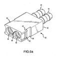
- FIG. 6a A geometric view of one configuration of an female intermediate connector assembly 50 is disclosed in Fig. 6a .
- hose ends 54 which are configured to compressibility fit within the attachment portion of a plurality hoses which may be further connectable, for example, to male connector 13.
- the connection ends may be replaced the one-piece hose structure with a plurality of flow channels formed therein.
- the one-piece hose structure is further connectable to the male machine connector 13.
- the female intermediate connector further includes fluid channels 51 and 53 which extend from the hose ends 54 through body portion 52.
- the channels exit through receiving end 58.
- Receiving end 58 is configured as a cavity in the body portion which is shaped to receive a portion of a male connector.
- the intermediate female connector disclosed in Figs. 5a-c is shown to include a single receiving end, other configurations of the female intermediate connector may include a plurality receiving ends wherein one female intermediate connector is connectable to a plurality of male intermediate connectors simultaneously.
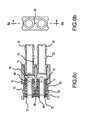
- a moveable valve device which is manipulable to open and close upon insertion of the male connector.
- a moveable valve device is positionable in each of the channels 51 and 53 for controlling the flow of medical fluid therethrough.
- a valve plunger 70 which has incorporated therein a number of openings 84, which depending on the position of the plunger in the channel, provide for fluid flow through the connector.
- springs 79 Surrounding the body portion of the valve plunger are springs 79, which are compressible against spring stop 71 when the male connector end is inserted. The insertion of the male intermediate connector end initiates movement of the plunger within the channels, such that the openings in the plunger are moved to a position which provides for circulation of the medical fluid.
- Each plunger further includes an o-ring seal 72 which contacts an internal surface of the connector end of the male connector intermediate assembly when inserted.
- the plunger seal 74 is further employable to move with the plunger device and provide a fluid seal even while the plunger is moving or is moved.
- a cap 73 which includes a valve seal 75 that provides for the sealing of the valve device upon removal of the male connector assembly. The sealing occurs when the valve spring decompresses and moves the plunger back towards the receiving end. At this point, the valve seal 75 contacts seat 84 and seals off any fluid flow therethrough.
- engagement surfaces 63 configured for receiving and engaging an engagement arm portion of the male intermiediate connector assembly.
- the engagement surface 63 is configured as a lip which interlocks with a corresponding lip configured on an engagement arm of an insertable male connector.
- orientation device 60 Disclosed in the view provided in Fig. 6b , is a view of orientation device 60 incorporated into the body portion 52.
- This orientation device provides a non-symmetrical feature to the receiving end 58 which in turn provides for the insertion of the male intermediate connector assembly at only a particular orientation. The desirability of this feature will be described in greater detail below.
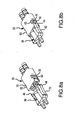
- FIG. 7a Views of one configuration of the male intermediate connector 30 configured to be interconnectable with the female intermediate connector described above are provided in Figs. 7a-c .
- Fig. 7a Disclosed in Fig. 7a is a geometric view of the male intermediate connector 30.
- the intermediate male connector includes a body portion 36 within which are formed fluid channels which pass from an insertion end 32 to a hose end 38.
- the hose end 38 is configured such that it is insertable within one end of a hose portion which in turn is interconnected and/or interconnectable to a patient temperature control pad or another connector.
- the removal/insertion arm 40 is configured to be employed in the insertion and removal of the male intermediate connector with an female intermediate connector.
- the insertion end 32 is configured to be insertable in an intermediate female connector assembly.
- insertion end 32 may be configured to contact one or more sealing devices within a portion of the female connector upon insertion so as to establish a fluid seal.
- fluid will pass from insertion end 32 unobstructed to hose end 38 and vice versa.
- a cross sectional view of one of the fluid channels 45 through the male connector is shown in detail in the view of Fig. 7c .
- flex arms 48 For engagement with the female connector assembly, extending from the body portion 36 are one or more flex arms 48.
- the flex arms may be constructed of a material which is the same or similar to the material use to form the body, wherein the flex arms have sufficient flexibility to deform about the point of the attachment of the flex arm to body 36.
- latch arm 42 Further attached to the flex arm is latch arm 42 which is rotatable about an attachment point to flex arm 48 when a force is applied. When the force is removed, the elasticity of flex arm returns the latch arm to its original position.
- the attachments arm portion 44 Opposite the latch arm portion is the attachments arm portion 44.
- an engagement lip 46 which is configured to interlock with a corresponding lip on an engagement surface of a female intermediate connector.
- the attachment arm and interlocking lip portion of the male intermediate connector assembly are configured such that when a force is applied to the latch arms which moves them closer to the body portion 36, the engagement arm portion rotates away from the first end 32.
- the elastic characteristics of the flex arm 48 returns the attachment arm with engagement lip to its original position so that the engagement lip 46 may contact a corresponding engagement surface on the female intermediate connector.
- orientation flange 50 extends between the channels incorporated into body 36 and provides the functionality such that the male intermediate connector assembly 30 may only be insertable in a female intermediate connector portion at a particular orientation. In essence, this orientation device provides a non-symmetric feature to the insertable portion of male intermediate connector assembly.
- Figs. 7a-d shows the engagement of the male and female connector assemblies while Fig. 8a shows the connectors in a disengaged state.
- the male and female intermediate connectors are first aligned.
- the orientation flange 50 on the male connector is positioned in a manner to as not to contact orientation device 60 upon insertion. More specifically, if the orientation device 60 contacts orientation ledge 50 on the male intermediate connector assembly, the male intermediate connector assembly is not insertable into the receiving end.
- orientation device 60 Conversely, if the orientation device 60 is opposite the orientation ledge 50, the male intermediate connector is insertable in the connector end and a fluid tight connection may be made.
- the orientation devices provide the advantage that the wrong channels through the male and female intermediate connectors will not be fluidly connected, potentially affecting circulation of the medical fluid through the system.
- attachment arms 42 Prior to insertion of the male intermediate connector in the female connector, a force may be applied to attachment arms 42, preferably with one hand using, for example, the thumb and forefinger, which moves the attachment arms towards the body portion and the engagement arms 44 with interlocking lip 46 far enough away so as to clear the exterior body of the female intermediate connector.
- the male intermediate connector end may then be inserted within the receiving end of the female intermediate connector such that the interior surface of the insertion of the insertion end contacts the o-ring seal 72 on the valve plunger 70 which in turn pushes the plunger and compresses the valve spring.
- the plunger is moved to the point that the openings in the plunger body allow for fluid flow through the female connector.
- FIG. 8d An example of an open valve within the female connector is shown in the cross sectional view provided in Fig. 8d .
- the valve spring 79 compressed and head 80, with seal 82, is moved clear of valve seat 84 thus providing a fluid through the connector.
- the fluid may flow in different directions in the different channels.
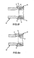
- Fig. 8e Disclosed in the view of Fig. 8e is a cross sectional view of the male connector and female connector in contact just prior to establishing the fluid tight seal.
- the male connector 30 includes an internal, tapered surface 77 which contacts an O ring 72 mounted on the valve plunger 70.
- the valve plunger 70 has an external tapered surface 81, that contacts the opposite side of the O-ring.
- the O-ring 72 rolls between the two tapered surfaces 77 and 81. During the insertion, the O-ring rolls rather than slides against the mating surfaces so that wear of the O-ring is minimized. Further, rolling rather than sliding also reduces the force required to engage the two connectors. Since the two surfaces in contact with the O-ring are tapered, the O-ring is compressed as the male connector is moved along the axis of the flow channel for the female intermediate connector.
- Fig.8f Shown in Fig.8f is a view of the male and female intermediate connectors fully engaged.
- the internal tapered surface 77 of the male connector has a larger taper angle than the external surface of the valve plunger, thus the O-ring is squeezed into a wedge shape.
- the O-ring gland area is tapered so that an increased vacuum inside the connectors pulls the O-ring into a smaller section of the gland. This increases the compression in the O-ring which, in turn, increases the contact stress between the O-ring and tapered surfaces. The result is that increased vacuum improves the seal by tightening the O-ring in the gland.
- the fluid tight seal described above is maintained by the mechanic engagement of the male and female intermediate connectors.
- the mechanical engagement of the male and female intermediate connectors may be better understood through further study of Fig. 8d .
- the latch arm and male connector may be released which in turn rotates the engagement lip 46 such that it contacts engagement area 56.
- Releasing the male connector has the further effect that the compressed valve springs begin to uncompress thus moving the engagement lip 46 into engagement surface 63, thus interlocking the two surfaces.
- the compressive force applied by the valve springs keeps the two surfaces in contact, and the diagonal direction, relatively, of the surfaces resists lateral movement of the engagement arm with respect to the female connector body thus maintaining engagement between the male and female connectors.
- an insertion force is applied to the male intermediate connector further moving the valve plunger and further compressing the valve spring.
- the further movement of the male intermediate connector acts to move the engagement devices and engagement surfaces clear of each other.
- Forces are then applied simultaneously (using the thumb and forefinger, for example) to all of the latch arms to move them towards the body of the male intermediate connector.
- the application of these forces acts to move the engagement arms 44 away from the body portion of the female intermediate connector, whereby maintaining the force on the latch arms the insertion force may be reversed and the male intermediate connector removed.
- the male machine connector 13 may be included as part of a connector assembly.
- This connector assembly may include a male machine connector 13, an intermediate one-piece hose section, as well as an intermediate female connector assembly.
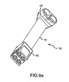
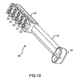
- the connector may be a unitary piece, in that it may be made up of a number of different pieces, and manufactured in manner such that it cannot be disassembled without damaging its function. Disclosed in Fig. 9a-f are various views of this connector assembly.
- Fig. 9a Disclosed in Fig. 9a is a geometric view of the connector including a male machine connector head 139 connected to the one-piece hose section 140 which in turn is connected to female connector assembly 150. As seen in Fig. 9b and the cross sectional view of Fig. 9e , incorporated into the hose section 140 are fluid channels 140 and 142. The channels are in communications with channels through the male machine connector and the female intermediate connector assembly portions. Hose section 140 may be formed out of any number of hard plastic, rubber, or composite materials of sufficient stiffness.
- the female machine connector assembly is configured to interconnect with a maximum of two male intermediate connector assemblies.
- Fig. 9d configured into the bottom of female connector assembly 150 are two receiving ends 171 and 173, where each end includes openings 170 and 172 to the fluid channels incorporated therein.
- each of the channels includes a valve assembly which operates in the same manner as described above for the intermediate female connector.
- a common manifold 166 which is further in communications with a channel, channel 142 in this view, of the hose section 140.
- each receiving end 171 and 173 includes a set of engagement surfaces 152 configured for engaging and interlocking with the engagement devices incorporated in the male connectors.
- the connector assembly 200 includes a female connector portion 202 with receiving ends 204-212 for interconnecting with a maximum 5 intermediate male connectors simultaneously.
- the configurations of the male machine connector assembly, especially the intermediate female connector, are exemplary, and one skilled in the art would know that the female intermediate connector portion can be configured with any number of receiving ends so as to connect with any number of male intermediate connectors.
- receiving ends may be incorporated in any number of surfaces of the intermediate female connector so as to facilitate the ergonomic design of the overall system.
Landscapes
- Engineering & Computer Science (AREA)
- Health & Medical Sciences (AREA)
- General Engineering & Computer Science (AREA)
- Heart & Thoracic Surgery (AREA)
- Public Health (AREA)
- Veterinary Medicine (AREA)
- Mechanical Engineering (AREA)
- Life Sciences & Earth Sciences (AREA)
- Animal Behavior & Ethology (AREA)
- General Health & Medical Sciences (AREA)
- Biomedical Technology (AREA)
- Physics & Mathematics (AREA)
- Thermal Sciences (AREA)
- Vascular Medicine (AREA)
- Pulmonology (AREA)
- Anesthesiology (AREA)
- Hematology (AREA)
- Quick-Acting Or Multi-Walled Pipe Joints (AREA)
- Infusion, Injection, And Reservoir Apparatuses (AREA)
- Thermotherapy And Cooling Therapy Devices (AREA)
Applications Claiming Priority (3)
| Application Number | Priority Date | Filing Date | Title |
|---|---|---|---|
| US215116 | 1988-07-05 | ||
| US10/215,116 US6827728B2 (en) | 2002-08-08 | 2002-08-08 | Patient temperature control system |
| PCT/US2003/023865 WO2004014268A1 (en) | 2002-08-08 | 2003-07-30 | Patient temperature control system |
Publications (3)
| Publication Number | Publication Date |
|---|---|
| EP1528905A1 EP1528905A1 (en) | 2005-05-11 |
| EP1528905A4 EP1528905A4 (en) | 2008-02-27 |
| EP1528905B1 true EP1528905B1 (en) | 2013-05-29 |
Family
ID=31494805
Family Applications (1)
| Application Number | Title | Priority Date | Filing Date |
|---|---|---|---|
| EP03784850.4A Expired - Lifetime EP1528905B1 (en) | 2002-08-08 | 2003-07-30 | Patient temperature control system |
Country Status (6)
| Country | Link |
|---|---|
| US (1) | US6827728B2 (enExample) |
| EP (1) | EP1528905B1 (enExample) |
| JP (1) | JP4597673B2 (enExample) |
| AU (1) | AU2003254272A1 (enExample) |
| CA (1) | CA2494907C (enExample) |
| WO (1) | WO2004014268A1 (enExample) |
Families Citing this family (72)
| Publication number | Priority date | Publication date | Assignee | Title |
|---|---|---|---|---|
| US7008445B2 (en) | 2002-04-29 | 2006-03-07 | Medcool, Inc. | Method and device for rapidly inducing hypothermia |
| US7052509B2 (en) | 2002-04-29 | 2006-05-30 | Medcool, Inc. | Method and device for rapidly inducing and then maintaining hypothermia |
| US8425579B1 (en) | 2002-10-08 | 2013-04-23 | Vitalwear, Inc. | Therapeutic knee brace for a contrast therapy system |
| US7694693B1 (en) | 2002-10-08 | 2010-04-13 | Vitalwear, Inc. | Mixing valve for a contrast therapy system |
| US8052628B1 (en) | 2002-10-08 | 2011-11-08 | Vitalwear, Inc. | Spinal column brace for a contrast therapy system |
| AU2003298629B2 (en) | 2002-12-12 | 2008-03-06 | Medcool, Inc. | Method and device for rapidly inducing and then maintaining hypothermia |
| US7658205B1 (en) | 2002-12-19 | 2010-02-09 | Vitalwear, Inc. | Systems for a fluid circuit coupler |
| US7191798B2 (en) * | 2002-12-19 | 2007-03-20 | Vital Wear, Inc. | Fluid circuit connector system |
| US7160316B2 (en) | 2003-09-24 | 2007-01-09 | Dynatherm Medical, Inc. | Methods and apparatus for adjusting body core temperature |
| US8182521B2 (en) | 2003-09-24 | 2012-05-22 | Dynatherm Medical Inc. | Methods and apparatus for increasing blood circulation |
| US7070612B1 (en) | 2005-02-23 | 2006-07-04 | Alsius Corporation | System and method for bringing hypothermia rapidly onboard |
| US7181927B2 (en) | 2005-07-01 | 2007-02-27 | Alsius Corporation | Primary heat exchanger for patient temperature control |
| US20070093697A1 (en) | 2005-10-21 | 2007-04-26 | Theranova, Llc | Method and apparatus for detection of right to left shunting in the cardiopulmonary vasculature |
| US20180311071A1 (en) | 2005-10-21 | 2018-11-01 | Daniel R. BURNETT | Method and apparatus for peritoneal oxygenation |
| US20070150033A1 (en) * | 2005-12-22 | 2007-06-28 | Cherlin Johnson | Cooling blanket |
| US7771461B2 (en) | 2006-08-24 | 2010-08-10 | Life Recovery Systems Hd, Llc | Apparatus for altering the body temperature of a patient |
| US7678716B2 (en) * | 2006-08-31 | 2010-03-16 | Kimberly-Clark Worldwide, Inc. | Hydrogel-web composites for thermal energy transfer applications and methods of making the same |
| US8257286B2 (en) | 2006-09-21 | 2012-09-04 | Tyco Healthcare Group Lp | Safety connector apparatus |
| US9918502B2 (en) * | 2006-09-21 | 2018-03-20 | Survitec Group Limited | Conditioning garments |
| US8529613B2 (en) | 2006-10-18 | 2013-09-10 | Medcool, Inc. | Adjustable thermal cap |
| US8603150B2 (en) | 2006-12-04 | 2013-12-10 | Carefusion 2200, Inc. | Methods and apparatus for adjusting blood circulation |
| US9308148B2 (en) | 2006-12-04 | 2016-04-12 | Thermatx, Inc. | Methods and apparatus for adjusting blood circulation |
| JP2010523230A (ja) | 2007-04-05 | 2010-07-15 | ベロメディックス,インク | 自動治療システム及び方法 |
| USD601248S1 (en) | 2007-05-18 | 2009-09-29 | Tyco Healthcare Group Lp | Connector and port arrangement with cylindrical segment tube retainers |
| US8092409B2 (en) | 2007-05-18 | 2012-01-10 | Tyco Healthcare Group Lp | Reinforced connector |
| USD595845S1 (en) | 2007-05-18 | 2009-07-07 | Tyco Healthcare Group Lp | Connector and port arrangement with arcuate tube retainers |
| US9044371B2 (en) * | 2007-06-13 | 2015-06-02 | Trailerlogic, Llc | Scalable and portable human remains cold storage system |
| CA2693774A1 (en) | 2007-07-09 | 2009-01-15 | Velomedix, Inc. | Hypothermia devices and methods |
| EP3677228B1 (en) | 2007-10-12 | 2024-07-10 | Medivance Incorporated | Improved system for patient temperature control |
| PL2209525T3 (pl) | 2007-11-16 | 2018-08-31 | Medivance Incorporated | Sposób i układ do kontroli reakcji pacjenta na temperaturę |
| US8257287B2 (en) | 2008-03-20 | 2012-09-04 | Tyco Healthcare Group Lp | Safety connector assembly |
| US20100080520A1 (en) * | 2008-05-12 | 2010-04-01 | Howard Lind | Flexible silicone cable system integrated with hollow tubing for fluid delivery |
| US8375572B2 (en) * | 2008-05-12 | 2013-02-19 | Howard Lind | Method for creating a silicone encased flexible cable |
| US8598461B2 (en) * | 2008-05-12 | 2013-12-03 | Howard Lind | Flexible self supporting encased silicone cable system and method |
| US8595922B2 (en) * | 2008-05-12 | 2013-12-03 | Howard Lind | Flexible silicone cable system integrated with snap washer |
| GB2498274B (en) * | 2008-10-08 | 2013-08-21 | Bedrock Inv S Llc | Shivering during therapeutic temperature control |
| US8264342B2 (en) | 2008-10-28 | 2012-09-11 | RF Surgical Systems, Inc | Method and apparatus to detect transponder tagged objects, for example during medical procedures |
| US9792408B2 (en) | 2009-07-02 | 2017-10-17 | Covidien Lp | Method and apparatus to detect transponder tagged objects and to communicate with medical telemetry devices, for example during medical procedures |
| AT508744B1 (de) * | 2009-09-11 | 2011-11-15 | Fronius Int Gmbh | Schlauchpaket, kupplungselement, steckerelement und steckverbindung für eine schweissvorrichtung sowie schweissvorrichtung |
| CN107115598A (zh) * | 2009-09-16 | 2017-09-01 | 德克萨斯大学体系董事会 | 改变哺乳动物身体的温度 |
| US9492314B2 (en) * | 2009-12-18 | 2016-11-15 | Trailerlogic, Llc | System for altering and maintaining temperatures of objects |
| CN102917674A (zh) | 2010-01-08 | 2013-02-06 | 康尔福盛2200公司 | 用于增强在附肢中的血管通路以加强治疗和介入治疗的方法和装置 |
| WO2012006625A2 (en) | 2010-07-09 | 2012-01-12 | Velomedix, Inc. | Method and apparatus for pressure measurement |
| WO2013074128A2 (en) | 2010-11-29 | 2013-05-23 | Board Of Regents, The University Of Texas System | Maintenance of reduced core mammalian body temperature |
| US9136597B2 (en) | 2011-03-17 | 2015-09-15 | Rf Surgical Systems, Inc. | Mat based antenna system to detect transponder tagged objects, for example during medical procedures |
| US9801756B2 (en) | 2012-09-28 | 2017-10-31 | Zoll Circulation, Inc. | Intravascular heat exchange catheter and system with RFID coupling |
| US10390992B2 (en) | 2013-05-20 | 2019-08-27 | Stryker Corporation | Thermal control system |
| US9474644B2 (en) | 2014-02-07 | 2016-10-25 | Zoll Circulation, Inc. | Heat exchange system for patient temperature control with multiple coolant chambers for multiple heat exchange modalities |
| US10792185B2 (en) | 2014-02-14 | 2020-10-06 | Zoll Circulation, Inc. | Fluid cassette with polymeric membranes and integral inlet and outlet tubes for patient heat exchange system |
| US11033424B2 (en) | 2014-02-14 | 2021-06-15 | Zoll Circulation, Inc. | Fluid cassette with tensioned polymeric membranes for patient heat exchange system |
| US10500088B2 (en) | 2014-02-14 | 2019-12-10 | Zoll Circulation, Inc. | Patient heat exchange system with two and only two fluid loops |
| US20150335467A1 (en) * | 2014-05-23 | 2015-11-26 | Carefusion 2200, Inc. | Patient warming system connection device |
| WO2016025268A2 (en) | 2014-08-14 | 2016-02-18 | Medivance Incorporated | System and method for extracorporeal temperature control |
| US11359620B2 (en) | 2015-04-01 | 2022-06-14 | Zoll Circulation, Inc. | Heat exchange system for patient temperature control with easy loading high performance peristaltic pump |
| US9784263B2 (en) | 2014-11-06 | 2017-10-10 | Zoll Circulation, Inc. | Heat exchange system for patient temperature control with easy loading high performance peristaltic pump |
| DE102014117009A1 (de) * | 2014-11-20 | 2016-05-25 | Valeo Klimasysteme Gmbh | Baugruppe mit einem Flansch und einer Prüfvorrichtung |
| JP6787903B2 (ja) | 2015-01-27 | 2020-11-18 | メディヴァンス インコーポレイテッドMedivance,Inc. | 熱療法用の改良された医療用パッド及びシステム |
| US11213423B2 (en) | 2015-03-31 | 2022-01-04 | Zoll Circulation, Inc. | Proximal mounting of temperature sensor in intravascular temperature management catheter |
| US10537465B2 (en) | 2015-03-31 | 2020-01-21 | Zoll Circulation, Inc. | Cold plate design in heat exchanger for intravascular temperature management catheter and/or heat exchange pad |
| US10022265B2 (en) | 2015-04-01 | 2018-07-17 | Zoll Circulation, Inc. | Working fluid cassette with hinged plenum or enclosure for interfacing heat exchanger with intravascular temperature management catheter |
| US10193209B2 (en) | 2015-04-06 | 2019-01-29 | Covidien Lp | Mat based antenna and heater system, for use during medical procedures |
| EP3181978B1 (en) | 2015-12-16 | 2020-05-06 | FASTER S.r.l. | Multiple coupling manifold for quick couplings |
| US11058572B2 (en) | 2016-10-11 | 2021-07-13 | Stryker Corporation | Thermal control system |
| US11185440B2 (en) | 2017-02-02 | 2021-11-30 | Zoll Circulation, Inc. | Devices, systems and methods for endovascular temperature control |
| US11116657B2 (en) | 2017-02-02 | 2021-09-14 | Zoll Circulation, Inc. | Devices, systems and methods for endovascular temperature control |
| DE202019001024U1 (de) * | 2019-03-01 | 2019-06-13 | Reinhold Kett | Multifunktionale, temperaturgeregelte Körperauflage (Kompresse) zur Kälte- und Wärmebehandlung von Gewebeflächen |
| WO2021231473A1 (en) | 2020-05-12 | 2021-11-18 | C. R. Bard, Inc. | System, method and apparatus for control of shivering during targeted temperature management |
| WO2021242892A1 (en) | 2020-05-29 | 2021-12-02 | C.R. Bard, Inc. | Systems and apparatuses for patient temperature control with patient heat generation detection |
| US12433785B2 (en) | 2021-02-23 | 2025-10-07 | C. R. Bard, Inc. | Gel pad assembly using free rotatable fluid joints |
| US12241570B2 (en) | 2021-07-07 | 2025-03-04 | C. R. Bard, Inc. | Negative pressure connector seal |
| US20230021245A1 (en) * | 2021-07-19 | 2023-01-19 | C. R. Bard, Inc. | Self-Sealing Membrane Connector for Gel Pads |
| WO2025133117A1 (fr) * | 2023-12-20 | 2025-06-26 | Valeo Systèmes d'Essuyage | Bloc hydraulique et ensemble d'électrovannes pour véhicule automobile |
Citations (2)
| Publication number | Priority date | Publication date | Assignee | Title |
|---|---|---|---|---|
| US4969879A (en) * | 1988-07-26 | 1990-11-13 | Gish Biomedical, Inc. | Body fluid interconnect |
| US5323808A (en) * | 1992-06-15 | 1994-06-28 | Sanden Corporation | Refrigerant charge connecting unit |
Family Cites Families (24)
| Publication number | Priority date | Publication date | Assignee | Title |
|---|---|---|---|---|
| US3425419A (en) * | 1964-08-08 | 1969-02-04 | Angelo Actis Dato | Method of lowering and raising the temperature of the human body |
| US3894213A (en) | 1973-08-23 | 1975-07-08 | Everest & Jennings | Fluid circulating heating pad |
| US4118946A (en) | 1976-11-23 | 1978-10-10 | Eddie Sam Tubin | Personnel cooler |
| US4691762A (en) * | 1983-04-01 | 1987-09-08 | Life Support Systems, Inc. | Personal temperature control system |
| US4508123A (en) | 1983-06-01 | 1985-04-02 | American Hospital Supply Corporation | Thermodilution injectate assembly |
| US4951665A (en) | 1989-02-08 | 1990-08-28 | Hollister Incorporated | Insulating, anti-kinking Y connector for arthroscopic surgery and method of making |
| US4982736A (en) * | 1989-02-08 | 1991-01-08 | Hollister Incorporated | Hermaphroditic coupling for anatomical thermal system |
| US5174285A (en) | 1990-01-08 | 1992-12-29 | Lake Shore Medical Development Partners Ltd. | Localized heat transfer device |
| US5097829A (en) | 1990-03-19 | 1992-03-24 | Tony Quisenberry | Temperature controlled cooling system |
| US5507792A (en) | 1990-09-05 | 1996-04-16 | Breg, Inc. | Therapeutic treatment device having a heat transfer element and a pump for circulating a treatment fluid therethrough |
| US5411541A (en) | 1993-08-05 | 1995-05-02 | Oansh Designs Ltd. | Portable fluid therapy device |
| US5470353A (en) | 1993-10-20 | 1995-11-28 | Hollister Incorporated | Post-operative thermal blanket |
| US5456701A (en) | 1994-02-25 | 1995-10-10 | Southwest Technologies, Inc. | Therapy member including internal bladder with surrounding pliable gel |
| USD364680S (en) | 1994-04-26 | 1995-11-28 | The Kendall Company | Connector for applying compressive pressure to the leg |
| US5895418A (en) | 1994-09-30 | 1999-04-20 | Saringer Research Inc. | Device for producing cold therapy |
| US5643191A (en) | 1995-01-26 | 1997-07-01 | Sorin Biomedical Inc. | Cardioplegia delivery system and method for converting from warm cardioplegia to cold cardioplegia |
| US5980561A (en) * | 1995-03-01 | 1999-11-09 | Kolen; Paul T. | Applying thermal therapy to living tissue |
| US5944362A (en) * | 1996-09-03 | 1999-08-31 | Kat Mfg., Inc. | Full flow and/or locking connector/quick-disconnect coupling |
| US6394138B1 (en) * | 1996-10-30 | 2002-05-28 | Unit Instruments, Inc. | Manifold system of removable components for distribution of fluids |
| EP1011752B1 (en) * | 1997-05-20 | 2004-10-13 | Zymequest, Inc. | Cell processing system and method for controlling it |
| CA2326812A1 (en) * | 1998-03-31 | 1999-10-07 | Hill-Rom, Inc. | Air-over-foam mattress |
| US6197045B1 (en) | 1999-01-04 | 2001-03-06 | Medivance Incorporated | Cooling/heating pad and system |
| US6238427B1 (en) | 1999-03-30 | 2001-05-29 | John G. Matta | Therapeutic heat transfer pads |
| US6302147B1 (en) * | 1999-04-08 | 2001-10-16 | Joseph Lorney Rose | Automatic dry release valve coupling |
-
2002
- 2002-08-08 US US10/215,116 patent/US6827728B2/en not_active Expired - Lifetime
-
2003
- 2003-07-30 WO PCT/US2003/023865 patent/WO2004014268A1/en not_active Ceased
- 2003-07-30 JP JP2004527680A patent/JP4597673B2/ja not_active Expired - Lifetime
- 2003-07-30 AU AU2003254272A patent/AU2003254272A1/en not_active Abandoned
- 2003-07-30 CA CA2494907A patent/CA2494907C/en not_active Expired - Lifetime
- 2003-07-30 EP EP03784850.4A patent/EP1528905B1/en not_active Expired - Lifetime
Patent Citations (2)
| Publication number | Priority date | Publication date | Assignee | Title |
|---|---|---|---|---|
| US4969879A (en) * | 1988-07-26 | 1990-11-13 | Gish Biomedical, Inc. | Body fluid interconnect |
| US5323808A (en) * | 1992-06-15 | 1994-06-28 | Sanden Corporation | Refrigerant charge connecting unit |
Also Published As
| Publication number | Publication date |
|---|---|
| EP1528905A1 (en) | 2005-05-11 |
| US20040030372A1 (en) | 2004-02-12 |
| JP4597673B2 (ja) | 2010-12-15 |
| CA2494907A1 (en) | 2004-02-19 |
| JP2005535387A (ja) | 2005-11-24 |
| US6827728B2 (en) | 2004-12-07 |
| CA2494907C (en) | 2012-09-25 |
| EP1528905A4 (en) | 2008-02-27 |
| AU2003254272A1 (en) | 2004-02-25 |
| WO2004014268A1 (en) | 2004-02-19 |
Similar Documents
| Publication | Publication Date | Title |
|---|---|---|
| EP1528905B1 (en) | Patient temperature control system | |
| CA2495506C (en) | Patient temperature control system connector apparatus | |
| JP2005535387A5 (enExample) | ||
| US5980506A (en) | Subcutaneous infusion device | |
| JP7104063B2 (ja) | 内視鏡接続用の装置および方法 | |
| US7191798B2 (en) | Fluid circuit connector system | |
| US9851037B2 (en) | Fluid connector and method for making sealed fluid connections | |
| WO2006127123A3 (en) | Locking catheter connector and method | |
| US8021353B2 (en) | Heat exchanger connector assembly | |
| HUP0201397A2 (en) | Needle-less luer activated medical connector | |
| US7305267B2 (en) | Connector module having reduced insertion force | |
| US20020084437A1 (en) | Valve assembly for medical manifold | |
| KR102362472B1 (ko) | 흡인세척장치 | |
| CN217285701U (zh) | 一种内窥镜转接装置 | |
| US6971680B2 (en) | Dialysis coupler assembly with joint members and hemodialysis system using same | |
| EP1434620A1 (en) | Male luer valve | |
| CN108506553B (zh) | 肿瘤热灌注装置及其二通阀 | |
| CN111939359B (zh) | 用于心肺机的具有闩锁机构的设备对接接口 | |
| CN219331877U (zh) | 接头组件、第一类型接头及第二类型接头 |
Legal Events
| Date | Code | Title | Description |
|---|---|---|---|
| PUAI | Public reference made under article 153(3) epc to a published international application that has entered the european phase |
Free format text: ORIGINAL CODE: 0009012 |
|
| 17P | Request for examination filed |
Effective date: 20050307 |
|
| AK | Designated contracting states |
Kind code of ref document: A1 Designated state(s): AT BE BG CH CY CZ DE DK EE ES FI FR GB GR HU IE IT LI LU MC NL PT RO SE SI SK TR |
|
| AX | Request for extension of the european patent |
Extension state: AL LT LV MK |
|
| DAX | Request for extension of the european patent (deleted) | ||
| RBV | Designated contracting states (corrected) |
Designated state(s): DE FR GB |
|
| A4 | Supplementary search report drawn up and despatched |
Effective date: 20080129 |
|
| 17Q | First examination report despatched |
Effective date: 20080618 |
|
| RAP1 | Party data changed (applicant data changed or rights of an application transferred) |
Owner name: MEDIVANCE INCORPORATED |
|
| REG | Reference to a national code |
Ref country code: DE Ref legal event code: R079 Ref document number: 60344181 Country of ref document: DE Free format text: PREVIOUS MAIN CLASS: A61F0007000000 Ipc: F16L0037120000 |
|
| GRAP | Despatch of communication of intention to grant a patent |
Free format text: ORIGINAL CODE: EPIDOSNIGR1 |
|
| RIC1 | Information provided on ipc code assigned before grant |
Ipc: F16L 37/098 20060101ALI20121123BHEP Ipc: F16L 37/127 20060101ALI20121123BHEP Ipc: F16L 37/133 20060101ALI20121123BHEP Ipc: F16L 37/12 20060101AFI20121123BHEP |
|
| GRAS | Grant fee paid |
Free format text: ORIGINAL CODE: EPIDOSNIGR3 |
|
| GRAA | (expected) grant |
Free format text: ORIGINAL CODE: 0009210 |
|
| AK | Designated contracting states |
Kind code of ref document: B1 Designated state(s): DE FR GB |
|
| REG | Reference to a national code |
Ref country code: GB Ref legal event code: FG4D |
|
| REG | Reference to a national code |
Ref country code: DE Ref legal event code: R096 Ref document number: 60344181 Country of ref document: DE Effective date: 20130725 |
|
| PLBE | No opposition filed within time limit |
Free format text: ORIGINAL CODE: 0009261 |
|
| STAA | Information on the status of an ep patent application or granted ep patent |
Free format text: STATUS: NO OPPOSITION FILED WITHIN TIME LIMIT |
|
| 26N | No opposition filed |
Effective date: 20140303 |
|
| REG | Reference to a national code |
Ref country code: DE Ref legal event code: R097 Ref document number: 60344181 Country of ref document: DE Effective date: 20140303 |
|
| REG | Reference to a national code |
Ref country code: FR Ref legal event code: PLFP Year of fee payment: 14 |
|
| REG | Reference to a national code |
Ref country code: FR Ref legal event code: PLFP Year of fee payment: 15 |
|
| REG | Reference to a national code |
Ref country code: FR Ref legal event code: PLFP Year of fee payment: 16 |
|
| REG | Reference to a national code |
Ref country code: DE Ref legal event code: R082 Ref document number: 60344181 Country of ref document: DE Representative=s name: D YOUNG & CO LLP, DE |
|
| PGFP | Annual fee paid to national office [announced via postgrant information from national office to epo] |
Ref country code: GB Payment date: 20220621 Year of fee payment: 20 |
|
| PGFP | Annual fee paid to national office [announced via postgrant information from national office to epo] |
Ref country code: FR Payment date: 20220622 Year of fee payment: 20 |
|
| PGFP | Annual fee paid to national office [announced via postgrant information from national office to epo] |
Ref country code: DE Payment date: 20220621 Year of fee payment: 20 |
|
| REG | Reference to a national code |
Ref country code: DE Ref legal event code: R071 Ref document number: 60344181 Country of ref document: DE |
|
| REG | Reference to a national code |
Ref country code: GB Ref legal event code: PE20 Expiry date: 20230729 |
|
| PG25 | Lapsed in a contracting state [announced via postgrant information from national office to epo] |
Ref country code: GB Free format text: LAPSE BECAUSE OF EXPIRATION OF PROTECTION Effective date: 20230729 |