EP1528796B1 - System und Vorrichtung zur Flimmerunterdrückung in verstärktem digitalen Videosignal - Google Patents
System und Vorrichtung zur Flimmerunterdrückung in verstärktem digitalen Videosignal Download PDFInfo
- Publication number
- EP1528796B1 EP1528796B1 EP04105330A EP04105330A EP1528796B1 EP 1528796 B1 EP1528796 B1 EP 1528796B1 EP 04105330 A EP04105330 A EP 04105330A EP 04105330 A EP04105330 A EP 04105330A EP 1528796 B1 EP1528796 B1 EP 1528796B1
- Authority
- EP
- European Patent Office
- Prior art keywords
- pixels
- frame
- pixel
- processor
- received frame
- Prior art date
- Legal status (The legal status is an assumption and is not a legal conclusion. Google has not performed a legal analysis and makes no representation as to the accuracy of the status listed.)
- Expired - Lifetime
Links
- 238000000034 method Methods 0.000 title claims description 24
- 230000001629 suppression Effects 0.000 claims description 17
- 239000000725 suspension Substances 0.000 claims 9
- 238000012986 modification Methods 0.000 claims 2
- 230000004048 modification Effects 0.000 claims 2
- 238000006467 substitution reaction Methods 0.000 description 17
- 230000002085 persistent effect Effects 0.000 description 10
- 238000012360 testing method Methods 0.000 description 9
- 238000013459 approach Methods 0.000 description 3
- 238000010586 diagram Methods 0.000 description 3
- 238000012545 processing Methods 0.000 description 3
- 230000000694 effects Effects 0.000 description 2
- 238000002474 experimental method Methods 0.000 description 2
- 230000006870 function Effects 0.000 description 2
- 230000004297 night vision Effects 0.000 description 2
- 230000000644 propagated effect Effects 0.000 description 2
- 230000002123 temporal effect Effects 0.000 description 2
- 238000012935 Averaging Methods 0.000 description 1
- 208000001140 Night Blindness Diseases 0.000 description 1
- 206010038910 Retinitis Diseases 0.000 description 1
- 230000002596 correlated effect Effects 0.000 description 1
- 238000001514 detection method Methods 0.000 description 1
- 230000009977 dual effect Effects 0.000 description 1
- 230000002708 enhancing effect Effects 0.000 description 1
- 238000003384 imaging method Methods 0.000 description 1
- 238000012544 monitoring process Methods 0.000 description 1
- 230000001902 propagating effect Effects 0.000 description 1
- 238000005070 sampling Methods 0.000 description 1
- 230000006641 stabilisation Effects 0.000 description 1
- 238000011105 stabilization Methods 0.000 description 1
Images

Classifications
-
- H—ELECTRICITY
- H04—ELECTRIC COMMUNICATION TECHNIQUE
- H04N—PICTORIAL COMMUNICATION, e.g. TELEVISION
- H04N23/00—Cameras or camera modules comprising electronic image sensors; Control thereof
- H04N23/80—Camera processing pipelines; Components thereof
- H04N23/81—Camera processing pipelines; Components thereof for suppressing or minimising disturbance in the image signal generation
-
- H—ELECTRICITY
- H04—ELECTRIC COMMUNICATION TECHNIQUE
- H04N—PICTORIAL COMMUNICATION, e.g. TELEVISION
- H04N23/00—Cameras or camera modules comprising electronic image sensors; Control thereof
- H04N23/70—Circuitry for compensating brightness variation in the scene
- H04N23/75—Circuitry for compensating brightness variation in the scene by influencing optical camera components
Definitions
- the present invention relates, in general, to imaging devices and, more specifically, to a system and method for suppression of scintillation noise from digital data produced by an intensified video camera
- Image intensification devices are constructed for a variety of applications. These devices are particularly useful for both industrial and military applications.
- image intensification devices are used in night vision goggles for enhancing the night vision of aviators and other military personnel performing covert operations. They are also employed in security cameras, photographing astronomical bodies and in medical instruments to help alleviate conditions such as retinitis pigmentosis, more commonly known as night blindness. Image intensification devices are currently manufactured in two types, commonly referred to as Generation II (GEN 2) and Generation III (GEN 3) type image intensifier (I 2 ) tubes.
- GEN 2 Generation II
- GEN 3 Generation III
- Image intensifier tubes inherently produce a type of noise known as scintillation noise. Scintillation appears as a random bright flash of very short duration in the output of the I 2 tube. In GEN III tubes, the flashes are typically 30 microns in size and persist for 1 to 3 milliseconds. A digital video camera mounted to an I 2 tube captures scintillation as one or more bright pixels. The camera exacerbates scintillation noise by extending the duration of each flash from several milliseconds to a full camera frame period. Scintillation noise suppression, therefore, is especially desirable in intensified video.
- the present invention addresses an improved system and method for scintillation suppression of video images.
- the present invention provides a method for scintillation suppression of video images as described in claim1, which in a preferred embodiment includes the steps of: (a) receiving a frame of pixels having intensity values; (b) identifying pixels in the received frame having scintillation noise; (c) modifying intensity values of pixels in the received frame, identified as having scintillation noise, to form a filtered frame of pixels; (d) counting the number of pixels modified in step (c); and (e) displaying the filtered frame of pixels, if the amount of pixels counted is less than a threshold value.
- the method of the invention may also include receiving previous and present frames of pixels, wherein step (c) includes storing a previously filtered frame of pixels in a buffer, and modifying intensity values of pixels in a presently received frame of pixels by using a previously filtered frame of pixels stored in the buffer.
- the invention includes a system for scintillation suppression as described in claim 12.
- the system may have a receiver for receiving a frame of pixels having intensity values, and a processor, coupled to the receiver.
- the processor is configured to (a) identify pixels in the received frame having scintillation noise, and (b) modify intensity values of pixels in the received frame identified as having scintillation noise, to form a filtered frame of pixels.
- a counter is included in the processor, for counting the number of pixels modified by the processor, and a display is included for displaying the filtered frame of pixels formed by the processor. The display displays the filtered frame of pixels, if the amount of pixels counted by the counter is less than a threshold value.
- the present invention suppresses scintillation noise using a video processor, which may be bandwidth and memory limited.
- the present invention is both computationally simple and may be implemented with a frame buffer having a storage capacity to hold data of a single video frame.
- the method includes step 11 for receiving a frame of pixels and step 12 for identifying pixels having a high probability of containing scintillation noise. Also included are step 14 for substituting the scintillation noise value of a pixel with a value close to that of what the camera would have recorded absent the scintillation noise, and step 15 for counting the number of substituted pixel values. As will be explained, step 16 effectively eliminates persistent false-positive artifacts occurring as a side effect of pixel substitution, by using the count number provided by a counter performing the counting in step 15.
- the modified frame may be displayed, in step 18, on a display.
- the step of identifying pixels that have a high probability of containing scintillation noise may be performed by comparing each new pixel, in real time, as the pixel is received from the camera, with the same spatially located pixel from the previous frame.
- the next step, value substitution may be performed by replacing the current pixel value with that of the value of the same spatially located pixel from the previous frame.
- steps 12 and 14 are effective when the video scene content is not highly dynamic.
- algorithms available that minimize scene dynamics in digital video.
- An example of such algorithm is motion stabilization, which minimizes the effect of camera motion.
- the inventor has discovered that even with such algorithms, the use of pixel substitution to remove noise may induce false-positive artifacts in the filtered scene. These artifacts may occur at image locations where pixels abruptly change from dim to bright and remain bright. If the change in pixel brightness meets a criteria for substitution, the bright pixel may be replaced with a dim pixel and the cycle may repeat indefinitely. As will be explained, step 16 of the method of the invention eliminates these false-positive artifacts.
- Step 16 of method 10 accomplishes this by monitoring the number of scintillation pixels that are substituted on a frame-by-frame basis. If the substitution count exceeds a threshold, then all pixel substitutions are suspended for one frame. This allows the unfiltered value of every pixel to be placed into a single video buffer, and breaks the cycle of persistent false-positives.
- the present invention also advantageously minimizes the number of persistent false-positive artifacts by limiting the amount of scintillation suppression performed in situations having highly dynamic scenes.
- a threshold may be set by a user that trades off scintillation noise for artifact noise. An algorithm for accomplishing these steps is described later.
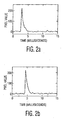
- FIGS. 2a and 2b two typical scintillation noise spikes are shown in FIGS. 2a and 2b .
- amplitude, or intensity is plotted versus time. These plots were obtained from a GEN III tube at a sampling rate of 3129 samples per second. Intensity is scaled using eight bits, thus, obtaining a range of 0 to 255.
- the intensity of each noise spike approaches the maximum detector value of 255, i.e. saturation.
- the duration of the spikes are approximately 2.5 milliseconds (ms).
- the short duration and high intensity of the noise spike are identified by the invention as scintillation noise.
- the scintillation noise appears bright against a normal video signal. If the minimum detection threshold for a scintillation pixel is set at a value of 127 (for example), the duration of the noise above this threshold is even shorter, or approximately 1 ms, as shown.
- the digital video content of an exemplary embodiment of the present invention is an eight-bit gray scale from a camera with a resolution of 1024 X 1280 pixels, mounted to a GEN III image intensifier (I 2 ) tube. It will be understood that the invention is not limited to this video format, but may be applied to any digital video stream, at any camera resolution, and to any pixel-encoding format, either black and white or color.
- a digital video camera exposes each pixel once per frame.
- each scintillation noise typically appears for only one frame in video cameras with frame rates below 500 frames per second.
- a camera with a 30Hz frame rate samples any pixel once every 33.3 ms.
- the exposure time for any pixel is approximately the frame period divided by the number of video lines.
- a camera with a frame rate of 30Hz and a vertical resolution of 1024 lines therefore, exposes each pixel for about 32.5 microseconds once every 33.3 milliseconds. Since both the period of exposure and the duration of the noise spike are small compared to the exposure time, it is unlikely for any given scintillation event to appear in more than one video frame.
- the value of a pixel exposed to scintillation noise is the sum of the scintillation intensity and the normal image intensity at that pixel location.
- the invention effectively identifies, with high probability, a pixel that contains scintillation noise.
- Such a pixel has a value higher than the value obtained from the previous frame, at the same pixel location, for a duration of one frame.
- the invention tests for scintillation noise by subtracting, on a pixel-by-pixel basis, the previous frame from the current frame. Subtractions that produce a positive result identify pixels that may contain scintillation noise. These pixels are then subjected to two additional tests in order to reduce the probability of a false-positive.
- the magnitude of the subtraction is tested against a threshold value. Results having a magnitude greater than the threshold value identify pixels that have a high probability of containing scintillation noise.
- an individual pixel only becomes noticeable to a viewer as noise, when it is relatively bright within the local scene. The contribution from a scintillation event may be anywhere from zero to saturation. Only when this contribution causes a pixel to appear bright, however, is that pixel a candidate for substitution. This second test uses a second threshold value which identifies bright pixels.
- the values of A and B may be dynamically adjusted from frame to frame.
- An algorithm may be used to optimize the values of A and/or B based on scene content.
- the inventor conducted experiments with an intensified video system to show excellent results using fixed values for parameters A and B.
- the experiments were conducted over a range of 10e-1 to 10e-6 foot-candles with a camera having a resolution of 1024 X 1280 pixels, mounted to a GEN III I 2 tube.
- the intensity is scaled to eight bits, providing a range of 0 to 255.
- Parameter A may be fixed at 127 (for example) and parameter B may be fixed at 96 (for example).
- V p,f-1 may be evaluated in Equation 1 instead of V' p,f-1 . If a pixel remains bright for two or more frames, S p,f would then be solved as being false, because V p,f-1 is approximately equal to V p,f .
- the number of scintillation noise events produced by an I 2 tube per unit time is random, having a Poisson distribution.
- the mean value of the number of scintillation events is highly correlated to the photo-multiplier tube gain.
- an embodiment of the present invention (shown in FIG. 3 ) estimates the number of scintillation events that may occur within one frame period. By counting the number of pixel substitutions performed during each frame, the invention determines if the number of substitutions exceeds an expected statistical value (or predetermined value).
- the ratio of the number of substitutions to the number of total camera pixels is low for frames with low scene dynamics. If this ratio increases above a predetermined value, then it is likely that many false-positive pixel substitutions have occurred. By suspending all substitutions for one full frame, the invention allows all pixels to be refreshed with current scene data, and eliminates any persistent false-positive artifacts.
- any pixel that abruptly and significantly increases in brightness may trigger pixel substitution.
- Events that may occur within a video image and cause abrupt and significant increases in brightness include a flash, a suddenly activated light source, an illuminated or highly reflective object moving into a scene, and a sudden increase in local scene luminance.
- An important difference, discovered by the inventor, between these types of scene changes and scintillation noise events is that scene changes tend to brighten a large number of pixels, whereas scintillation noise events only brightens a few pixels.
- An I 2 tube produces from 0 to a few hundred scintillations per camera frame, depending on the tube gain. If sign ificantly more pixels are counted in frame(f) than predicted, then the probability of false-positives increases proportionally. As a result, the invention halts scintillation suppression on the next frame(f+1), and unfiltered incoming pixel data is placed into the video buffer, thereby overwriting previously stored pixel values. Scintillation suppression may then resume on subsequent frames, without propagating false-positives.
- scintillation spikes within an I 2 tube typically, subtend less than a 30 micron time period. This is equivalent to 9 pixels on a camera with a resolution of 1024 X 1280 pixels, mounted on a GEN III I 2 tube. Based on experimentation, the inventor discovered that, of these 9 pixels, only 4 or 5 may be bright enough to trigger substitution. Accordingly, if the I 2 tube produces two hundred scintillations per camera frame at high gain, then the reference camera may produce about a 1000 pixels passing the criteria of Equation 1. If significantly more than 1000 pixels are counted in frame(f), then the probability of false-positives is high.
- the invention therefore, sets the suspend-threshold for frame(f) equal to the number of pixels in frame(f-1) satisfying Equation 1 plus 10%. Then, an increase in brightness of 100 additional pixels in frame(f) with respect to frame(f-1) halts scintillation suppression on frame(f+1). It will be understood that the invention is not limited to this value (plus 10%) of the suspend-threshold, but other values are also contemplated by the invention. For example, plus 5% to plus 25% may also be used as a suspend-threshold.
- any scene event that quantitatively brightens more than 100 pixels above a margin may result in the removal of persistent false-positive artifacts.
- a margin for example, a 1000 pixels satisfying Equation 1
- the size of the threshold margin determines the amount of scene dynamics allowed before scintillation suppression is reduced. It also determines the maximum number of false-positive artifacts allowed in the scene.
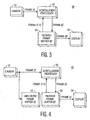
- intensified video camera 31 is coupled to scintillation processor 32 for providing a sequence of video frames for processing.
- Each frame provided by camera 31 is denoted as frame(f), the present frame.
- scintillation processor 32 receives the previously buffered filtered frame (f-1)' from filtered frame buffer 33.
- scintillation processor 32 compares the previously buffered filtered frame (f-1)' with the present camera frame(f). If Equation 1 is satisfied, on a pixel by pixel basis, and if suppression is not suspended in accordance with the algorithm listed in table 1, then a presently filtered frame(f)' is delivered to display 34, on a pixel by pixel basis. If, on the other hand, suppression is suspended due to an excessive amount of false-positives, then a presently unfiltered frame(f) is sent to display 34, on a pixel by pixel basis.
- FIG. 4 depicts scintillation noise suppression system 40, having elements similar to elements shown in FIG. 3 , namely camera 31, filtered frame buffer(f)' 33 and display 34.
- An additional buffer, namely unfiltered frame buffer(f) 41, is coupled between camera 31 and scintillation processor 42, as shown.
- the unfiltered frame buffer stores a present frame(f) arriving from camera 31.
- scintillation processor 42 receives the previously buffered unfiltered frame(f-1) from frame buffer 41. Accordingly, scintillation processor 42 compares the previously buffered unfiltered frame(f-1) with the present camera frame(f). If Equation 1 is satisfied, on a pixel by pixel basis, then presently filtered frame(f)' is delivered to display 34, by way of filtered frame buffer 33, on a pixel by pixel basis.
- the single buffer approach shown in FIG. 3 , has only one frame buffer.
- the scintillation processor has only the pre-filtered pixels from the previous buffered frame (V' p,f-1 ) to compare against pixels from the present camera frame, (V p,f ).
- a false-positive becomes persistent, because the processor does not test against the unprocessed buffered camera data, but instead the processor tests against filtered data.
- the filtered pixel (V' p,f-m ) continues to be substituted as long as the camera pixel from the incoming frame is bright and satisfies the criteria for scintillation of Equation 1. Therefore, an algorithm, similar to that shown in table 1 for detecting and removing persistent false-positives is incorporated by the invention.
- the dual buffer approach shown in FIG. 4 , however, stores both the filtered and the unfiltered pixel data from the current camera frame.
- the scintillation test may, thus, be made by the processor between the unfiltered pixels from the previous buffered frame (V p,f-1 ) and pixels from the present camera frame, (V p,f ). Since the filtered data (V' p,f-1 ) is not utilized in the scintillation test, false-positives are not propagated forward. They appear for a single frame and then are automatically over written. There is no need for further processing.
- this invention is applicable to any system which makes use of intensified digital video in low light applications, especially when that system is limited to a single video frame buffer and/or has constraints on video data processing throughput.
Landscapes
- Engineering & Computer Science (AREA)
- Multimedia (AREA)
- Signal Processing (AREA)
- Nuclear Medicine (AREA)
- Apparatus For Radiation Diagnosis (AREA)
Claims (20)
- Verfahren zur Szintillationsunterdrückung von Videobildern, das die folgenden Schritte umfasst:(a) Empfangen eines Rahmens von Pixeln, die Intensitätswerte besitzen;(b) Identifizieren von Pixeln in dem empfangenen Rahmen, die Szintillationsrauschen aufweisen;(c) Ändern der Intensitätswerte der Pixel in dem empfangenen Rahmen, die als Szintillationsrauschen aufweisend identifiziert wurden, um einen gefilterten Rahmen von Pixeln zu bilden;(d) Zählen der in Schritt (c) geänderten Pixel; und(e) Anzeigen des gefilterten Rahmens von Pixeln, wenn die Anzahl der gezählten Pixel unter einem Grenzwert liegt.
- Verfahren nach Anspruch 1, das das Empfangen vorheriger und derzeitiger Rahmen von Pixeln enthält, wobei
Schritt (c) enthält, einen vorher gefilterten Rahmen in einem Puffer abzuspeichern und die Intensitätswerte von Pixeln in einem derzeit empfangenen Rahmen von Pixeln durch Verwendung eines in dem Puffer gespeicherten vorher gefilterten Rahmens von Pixeln zu ändern. - Verfahren nach Anspruch 2, wobei das Ändern der Intensitätswerte der Pixel des derzeit empfangenen Rahmens von Pixeln Folgendes enthält:Ersetzen eines Pixels an einem zweidimensionalen Ort des derzeit empfangenen Rahmens von Pixeln durch ein weiteres Pixel an demselben zweidimensionalen Ort des vorher gefilterten Rahmens von Pixeln.
- Verfahren nach Anspruch 3, wobei das Ersetzen des Pixels des derzeit empfangenen Rahmens durch das Pixel des vorher empfangenen Rahmens Folgendes enthält:Ersetzen des Pixels des derzeit empfangenen Rahmens nur dann, wenn der Intensitätswert des Pixels größer als ein erster vorgegebener Grenzwert ist.
- Verfahren nach Anspruch 4, wobei das Ersetzen des Pixels des derzeit empfangenen Rahmens durch das Pixel des vorher empfangenen Rahmens ferner enthält:Ersetzen des Pixels nur dann, wenn der Unterschied zwischen dem Intensitätswert des Pixels des derzeit empfangenen Rahmens und dem Intensitätswert des Pixels des vorher empfangenen Rahmens größer als ein zweiter vorgegebener Grenzwert ist.
- Verfahren nach Anspruch 5, das den folgenden Schritt enthält:dynamisches Anpassen des ersten und/oder des zweiten vorgegebenen Grenzwertes auf einer rahmenweisen Basis.
- Verfahren nach Anspruch 5, das den folgenden Schritt enthält:Setzen des ersten vorgegebenen Grenzwertes auf einen größeren Wert als den zweiten vorgegebenen Grenzwert.
- Verfahren nach Anspruch 1, das ferner die folgenden Schritte enthält:(f) Setzen einer Zahl eines Aussetzungsgrenzwerts;(g) Vergleichen der Zahl des Aussetzungsgrenzwerts mit der in Schritt (d) gezählten Anzahl der Pixel; und(h) Aussetzen des Schritts (c), wenn die Anzahl der in Schritt (d) gezählten Pixel größer als die Zahl des Aussetzungsgrenzwerts ist.
- Verfahren nach Anspruch 8, wobei
das Setzen der Zahl des Aussetzungsgrenzwerts auf einer Menge der Vorgangsdynamik in dem empfangenen Rahmen von Pixeln beruht. - Verfahren nach Anspruch 8, das das Empfangen von vorherigen und derzeitigen Rahmen von Pixeln enthält, wobei
das Setzen der Zahl des Aussetzungsgrenzwerts auf einer Menge von Pixeln eines vorher empfangenen Rahmens, die in Schritt (c) geändert wurden, zuzüglich ungefähr 10 % beruht. - Verfahren nach Anspruch 10, das ferner den folgenden Schritt enthält:Speichern eines vorher gefilterten Rahmens von Pixeln in einem Puffer undwobei Schritt (e) das Anzeigen des in dem Puffer gespeicherten vorher gefilterten Rahmens von Pixeln enthält, falls Schritt (h) den Schritt (c) aussetzt.
- System zur Szintillationsunterdrückung, das umfasst:einen Empfänger zum Empfangen eines Rahmens von Pixeln, die Intensitätswerte besitzen,eine Verarbeitungseinheit, die an den Empfänger gekoppelt ist, zum(a) Identifizieren der Pixel in dem empfangenen Rahmen, die Szintillationsrauschen aufweisen, und(b) Ändern der Intensitätswerte der Pixel in dem empfangenen Rahmen, die als Szintillationsrauschen aufweisend identifiziert wurden, um einen gefilterten Rahmen von Pixeln zu bilden,eine in der Verarbeitungseinheit enthaltene Zählvorrichtung zum Zählen der Anzahl der durch die Verarbeitungseinheit geänderten Pixel undeine Anzeigevorrichtung zum Anzeigen des durch die Verarbeitungseinheit gebildeten gefilterten Rahmens von Pixeln, wobei die Anzeigevorrichtung den gefilterten Rahmen von Pixeln anzeigt, wenn die Menge der durch die Zählvorrichtung gezählten Pixel unter einem Grenzwert liegt.
- System nach Anspruch 12, wobei
der Empfänger dafür ausgelegt ist, vorherige und derzeitige Rahmen von Pixeln zu empfangen,
ein erster Puffer an die Verarbeitungseinheit zum Speichern der vorher gefilterten Rahmen von Pixeln gekoppelt ist und
die Verarbeitungseinheit dafür ausgelegt ist, die Intensitätswerte eines derzeit empfangenen Rahmens von Pixeln aufgrund des in dem Puffer gespeicherten vorher gefilterten Rahmens von Pixeln zu ändern. - Verfahren nach Anspruch 13, wobei
die Verarbeitungseinheit ausgelegt ist, ein Pixel an einem zweidimensionalen Ort des derzeit empfangenen Rahmens von Pixeln durch ein weiteres Pixel an demselben zweidimensionalen Ort des vorher gefilterten Rahmens von Pixeln zu ersetzen. - System nach Anspruch 14, wobei
die Verarbeitungseinheit dafür ausgelegt ist, das Pixel des derzeit empfangenen Rahmens nur dann zu ersetzen, wenn der Intensitätswert des Pixels größer als ein vorgegebener Grenzwert ist. - System nach Anspruch 14, wobei
die Verarbeitungseinheit dafür ausgelegt ist, das Pixel nur dann zu ersetzen, wenn der Unterschied zwischen dem Intensitätswert des Pixels des derzeit empfangenen Rahmens und dem Intensitätswert des Pixels des vorher empfangenen Rahmens größer als ein zweiter vorgegebener Grenzwert ist. - System nach Anspruch 14, wobei
die Verarbeitungseinheit einen Aussetzungsgrenzwert und
eine Vergleichsvorrichtung zum Vergleichen der Anzahl der durch die Verarbeitungseinheit in dem derzeit gefilterten Rahmen von Pixeln ersetzten Pixel mit dem Aussetzungsgrenzwert enthält und
die Verarbeitungseinheit die Änderung der Intensitätswerte der Pixel in dem derzeit empfangenen Rahmen aussetzt, wenn die Vergleichsvorrichtung bestimmt, dass die Anzahl der durch die Verarbeitungseinheit in dem derzeit gefilterten Rahmen von Pixeln ersetzten Pixel größer als der Aussetzungsgrenzwert ist. - System nach Anspruch 17, wobei
der Aussetzungsgrenzwert auf der Anzahl der in einem vorher gefilterten Rahmen ersetzten Pixel zuzüglich ungefähr 10 % beruht. - System nach Anspruch 13, wobei
ein zweiter Puffer an die Verarbeitungseinheit zum Speichern eines vorher empfangenen Rahmens von Pixeln, in dem die Pixel frei von jeder Änderung durch die Verarbeitungseinheit sind, gekoppelt ist, und
die Verarbeitungseinheit dafür ausgelegt ist, den derzeit empfangenen Rahmen von Pixeln anhand des in dem zweiten Puffer gespeicherten vorher empfangenen Rahmen von Pixeln zu ändern, und
die Verarbeitungseinheit dafür ausgelegt ist, den gefilterten Rahmen von Pixeln in dem ersten Puffer abzuspeichern. - System nach Anspruch 19, wobei
die Anzeigevorrichtung dafür ausgelegt ist, den in dem ersten Puffer gespeicherten gefilterten Rahmen von Pixeln anzuzeigen.
Applications Claiming Priority (2)
| Application Number | Priority Date | Filing Date | Title |
|---|---|---|---|
| US697198 | 2003-10-30 | ||
| US10/697,198 US7289683B2 (en) | 2003-10-30 | 2003-10-30 | System and method for scintillation suppression in intensified digital video |
Publications (3)
| Publication Number | Publication Date |
|---|---|
| EP1528796A2 EP1528796A2 (de) | 2005-05-04 |
| EP1528796A3 EP1528796A3 (de) | 2009-02-25 |
| EP1528796B1 true EP1528796B1 (de) | 2012-08-15 |
Family
ID=34423389
Family Applications (1)
| Application Number | Title | Priority Date | Filing Date |
|---|---|---|---|
| EP04105330A Expired - Lifetime EP1528796B1 (de) | 2003-10-30 | 2004-10-27 | System und Vorrichtung zur Flimmerunterdrückung in verstärktem digitalen Videosignal |
Country Status (3)
| Country | Link |
|---|---|
| US (1) | US7289683B2 (de) |
| EP (1) | EP1528796B1 (de) |
| IL (1) | IL164435A (de) |
Families Citing this family (2)
| Publication number | Priority date | Publication date | Assignee | Title |
|---|---|---|---|---|
| US7466873B2 (en) * | 2005-06-29 | 2008-12-16 | Xerox Corporation | Artifact removal and quality assurance system and method for scanned images |
| US8800870B1 (en) * | 2013-02-15 | 2014-08-12 | Raytheon Company | Short-wave infrared based scope |
Family Cites Families (11)
| Publication number | Priority date | Publication date | Assignee | Title |
|---|---|---|---|---|
| US3959583A (en) * | 1975-01-21 | 1976-05-25 | Bell Telephone Laboratories, Incorporated | Animated dithered display systems |
| US3937878A (en) * | 1975-01-21 | 1976-02-10 | Bell Telephone Laboratories, Incorporated | Animated dithered display systems |
| US4298944A (en) * | 1979-06-22 | 1981-11-03 | Siemens Gammasonics, Inc. | Distortion correction method and apparatus for scintillation cameras |
| JP2659213B2 (ja) * | 1988-06-07 | 1997-09-30 | 富士通株式会社 | 接触型指紋検出装置 |
| US5254982A (en) * | 1989-01-13 | 1993-10-19 | International Business Machines Corporation | Error propagated image halftoning with time-varying phase shift |
| JP3311175B2 (ja) * | 1993-11-18 | 2002-08-05 | キヤノン株式会社 | 画像処理方法及びその装置 |
| US6101287A (en) * | 1998-05-27 | 2000-08-08 | Intel Corporation | Dark frame subtraction |
| KR100340052B1 (ko) * | 1998-06-30 | 2002-07-18 | 박종섭 | 이미지센서 |
| US6243504B1 (en) * | 1998-08-19 | 2001-06-05 | International Business Machines Corporation | Integrated magnetic ink character recognition system and method therefor |
| US6747697B1 (en) * | 2000-07-12 | 2004-06-08 | Koninklijke Philips Electronics, N.V. | Method and apparatus for digital image defect correction and noise filtering |
| US6898331B2 (en) * | 2002-08-28 | 2005-05-24 | Bae Systems Aircraft Controls, Inc. | Image fusion system and method |
-
2003
- 2003-10-30 US US10/697,198 patent/US7289683B2/en not_active Expired - Fee Related
-
2004
- 2004-10-05 IL IL164435A patent/IL164435A/en not_active IP Right Cessation
- 2004-10-27 EP EP04105330A patent/EP1528796B1/de not_active Expired - Lifetime
Also Published As
| Publication number | Publication date |
|---|---|
| EP1528796A3 (de) | 2009-02-25 |
| US20050094888A1 (en) | 2005-05-05 |
| US7289683B2 (en) | 2007-10-30 |
| EP1528796A2 (de) | 2005-05-04 |
| IL164435A (en) | 2010-05-31 |
| IL164435A0 (en) | 2005-12-18 |
Similar Documents
| Publication | Publication Date | Title |
|---|---|---|
| US5949918A (en) | Method and apparatus for performing image enhancement | |
| EP2833618B1 (de) | Verfahren zum Aktivieren und Deaktivieren einer Bildkorrekturfunktion, Kamerasystem und Kraftfahrzeug | |
| CN104952045B (zh) | 除雾系统和除雾方法 | |
| US6681058B1 (en) | Method and apparatus for estimating feature values in a region of a sequence of images | |
| CN103856721B (zh) | 用于计算闪烁评估值的设备和方法 | |
| EP3879814A1 (de) | Verfahren und vorrichtung zur automatischen erkennung und unterdrückung von interferenzmustern, elektronische vorrichtung und computerlesbares speichermedium | |
| US8081224B2 (en) | Method and apparatus for image stabilization using multiple image captures | |
| EP0973128B1 (de) | Selektive Helligkeitserweiterung | |
| US7831063B2 (en) | Small event detector in presence of clutter | |
| US20090161756A1 (en) | Method and apparatus for motion adaptive pre-filtering | |
| US7202902B2 (en) | Image monitor apparatus controlling camera and illumination in order to optimize luminance of picked-up image | |
| CN106127693B (zh) | 除雾系统和除雾方法 | |
| KR100721543B1 (ko) | 통계적 정보를 이용하여 노이즈를 제거하는 영상 처리 방법및 시스템 | |
| US8446503B1 (en) | Imaging system | |
| KR20200039782A (ko) | 이미징 디바이스 및 이미징 방법 | |
| KR20100036601A (ko) | 영상 잡음 제거 장치 및 방법 | |
| JP2022548668A (ja) | 画像における複数の光源のフリッカ現象の低減 | |
| EP1528796B1 (de) | System und Vorrichtung zur Flimmerunterdrückung in verstärktem digitalen Videosignal | |
| EP3930307B1 (de) | Verfahren zur verbesserung der leistung einer videokamera | |
| KR102199472B1 (ko) | 화상 처리 장치 및 화상 처리 방법 | |
| US5296930A (en) | Noise reduction processing device for video signals by arbitration of pixel intensities | |
| JP5029573B2 (ja) | 撮像装置及び撮像方法 | |
| WO2012172728A1 (ja) | 画像処理システム | |
| US20250095113A1 (en) | Gaze-directed denoising in multi-camera systems | |
| US7474797B2 (en) | Spacial-temporal processing of digital images |
Legal Events
| Date | Code | Title | Description |
|---|---|---|---|
| PUAI | Public reference made under article 153(3) epc to a published international application that has entered the european phase |
Free format text: ORIGINAL CODE: 0009012 |
|
| AK | Designated contracting states |
Kind code of ref document: A2 Designated state(s): AT BE BG CH CY CZ DE DK EE ES FI FR GB GR HU IE IT LI LU MC NL PL PT RO SE SI SK TR |
|
| AX | Request for extension of the european patent |
Extension state: AL HR LT LV MK |
|
| PUAL | Search report despatched |
Free format text: ORIGINAL CODE: 0009013 |
|
| AK | Designated contracting states |
Kind code of ref document: A3 Designated state(s): AT BE BG CH CY CZ DE DK EE ES FI FR GB GR HU IE IT LI LU MC NL PL PT RO SE SI SK TR |
|
| AX | Request for extension of the european patent |
Extension state: AL HR LT LV MK |
|
| AKX | Designation fees paid |
Designated state(s): AT BE BG CH CY CZ DE DK EE ES FI FR GB GR HU IE IT LI LU MC NL PL PT RO SE SI SK TR |
|
| 17P | Request for examination filed |
Effective date: 20090825 |
|
| REG | Reference to a national code |
Ref country code: DE Ref legal event code: R079 Ref document number: 602004038894 Country of ref document: DE Free format text: PREVIOUS MAIN CLASS: H04N0005213000 Ipc: H04N0005217000 |
|
| GRAP | Despatch of communication of intention to grant a patent |
Free format text: ORIGINAL CODE: EPIDOSNIGR1 |
|
| RIC1 | Information provided on ipc code assigned before grant |
Ipc: H04N 5/238 20060101ALI20120208BHEP Ipc: H04N 5/217 20110101AFI20120208BHEP |
|
| RAP1 | Party data changed (applicant data changed or rights of an application transferred) |
Owner name: EXELIS INC. |
|
| GRAS | Grant fee paid |
Free format text: ORIGINAL CODE: EPIDOSNIGR3 |
|
| GRAA | (expected) grant |
Free format text: ORIGINAL CODE: 0009210 |
|
| AK | Designated contracting states |
Kind code of ref document: B1 Designated state(s): AT BE BG CH CY CZ DE DK EE ES FI FR GB GR HU IE IT LI LU MC NL PL PT RO SE SI SK TR |
|
| REG | Reference to a national code |
Ref country code: CH Ref legal event code: EP Ref country code: GB Ref legal event code: FG4D Ref country code: AT Ref legal event code: REF Ref document number: 571335 Country of ref document: AT Kind code of ref document: T Effective date: 20120815 |
|
| REG | Reference to a national code |
Ref country code: IE Ref legal event code: FG4D |
|
| REG | Reference to a national code |
Ref country code: DE Ref legal event code: R096 Ref document number: 602004038894 Country of ref document: DE Effective date: 20121011 |
|
| REG | Reference to a national code |
Ref country code: NL Ref legal event code: T3 |
|
| REG | Reference to a national code |
Ref country code: AT Ref legal event code: MK05 Ref document number: 571335 Country of ref document: AT Kind code of ref document: T Effective date: 20120815 |
|
| PG25 | Lapsed in a contracting state [announced via postgrant information from national office to epo] |
Ref country code: AT Free format text: LAPSE BECAUSE OF FAILURE TO SUBMIT A TRANSLATION OF THE DESCRIPTION OR TO PAY THE FEE WITHIN THE PRESCRIBED TIME-LIMIT Effective date: 20120815 Ref country code: FI Free format text: LAPSE BECAUSE OF FAILURE TO SUBMIT A TRANSLATION OF THE DESCRIPTION OR TO PAY THE FEE WITHIN THE PRESCRIBED TIME-LIMIT Effective date: 20120815 Ref country code: CY Free format text: LAPSE BECAUSE OF FAILURE TO SUBMIT A TRANSLATION OF THE DESCRIPTION OR TO PAY THE FEE WITHIN THE PRESCRIBED TIME-LIMIT Effective date: 20120815 |
|
| PGFP | Annual fee paid to national office [announced via postgrant information from national office to epo] |
Ref country code: FR Payment date: 20121107 Year of fee payment: 9 Ref country code: DE Payment date: 20121029 Year of fee payment: 9 |
|
| PG25 | Lapsed in a contracting state [announced via postgrant information from national office to epo] |
Ref country code: PL Free format text: LAPSE BECAUSE OF FAILURE TO SUBMIT A TRANSLATION OF THE DESCRIPTION OR TO PAY THE FEE WITHIN THE PRESCRIBED TIME-LIMIT Effective date: 20120815 Ref country code: SI Free format text: LAPSE BECAUSE OF FAILURE TO SUBMIT A TRANSLATION OF THE DESCRIPTION OR TO PAY THE FEE WITHIN THE PRESCRIBED TIME-LIMIT Effective date: 20120815 Ref country code: GR Free format text: LAPSE BECAUSE OF FAILURE TO SUBMIT A TRANSLATION OF THE DESCRIPTION OR TO PAY THE FEE WITHIN THE PRESCRIBED TIME-LIMIT Effective date: 20121116 Ref country code: PT Free format text: LAPSE BECAUSE OF FAILURE TO SUBMIT A TRANSLATION OF THE DESCRIPTION OR TO PAY THE FEE WITHIN THE PRESCRIBED TIME-LIMIT Effective date: 20121217 Ref country code: BE Free format text: LAPSE BECAUSE OF FAILURE TO SUBMIT A TRANSLATION OF THE DESCRIPTION OR TO PAY THE FEE WITHIN THE PRESCRIBED TIME-LIMIT Effective date: 20120815 Ref country code: SE Free format text: LAPSE BECAUSE OF FAILURE TO SUBMIT A TRANSLATION OF THE DESCRIPTION OR TO PAY THE FEE WITHIN THE PRESCRIBED TIME-LIMIT Effective date: 20120815 |
|
| PGFP | Annual fee paid to national office [announced via postgrant information from national office to epo] |
Ref country code: GB Payment date: 20121025 Year of fee payment: 9 |
|
| PGFP | Annual fee paid to national office [announced via postgrant information from national office to epo] |
Ref country code: NL Payment date: 20121024 Year of fee payment: 9 |
|
| PG25 | Lapsed in a contracting state [announced via postgrant information from national office to epo] |
Ref country code: DK Free format text: LAPSE BECAUSE OF FAILURE TO SUBMIT A TRANSLATION OF THE DESCRIPTION OR TO PAY THE FEE WITHIN THE PRESCRIBED TIME-LIMIT Effective date: 20120815 Ref country code: RO Free format text: LAPSE BECAUSE OF FAILURE TO SUBMIT A TRANSLATION OF THE DESCRIPTION OR TO PAY THE FEE WITHIN THE PRESCRIBED TIME-LIMIT Effective date: 20120815 Ref country code: ES Free format text: LAPSE BECAUSE OF FAILURE TO SUBMIT A TRANSLATION OF THE DESCRIPTION OR TO PAY THE FEE WITHIN THE PRESCRIBED TIME-LIMIT Effective date: 20121126 Ref country code: EE Free format text: LAPSE BECAUSE OF FAILURE TO SUBMIT A TRANSLATION OF THE DESCRIPTION OR TO PAY THE FEE WITHIN THE PRESCRIBED TIME-LIMIT Effective date: 20120815 Ref country code: CZ Free format text: LAPSE BECAUSE OF FAILURE TO SUBMIT A TRANSLATION OF THE DESCRIPTION OR TO PAY THE FEE WITHIN THE PRESCRIBED TIME-LIMIT Effective date: 20120815 |
|
| PG25 | Lapsed in a contracting state [announced via postgrant information from national office to epo] |
Ref country code: MC Free format text: LAPSE BECAUSE OF NON-PAYMENT OF DUE FEES Effective date: 20121031 Ref country code: SK Free format text: LAPSE BECAUSE OF FAILURE TO SUBMIT A TRANSLATION OF THE DESCRIPTION OR TO PAY THE FEE WITHIN THE PRESCRIBED TIME-LIMIT Effective date: 20120815 Ref country code: IT Free format text: LAPSE BECAUSE OF FAILURE TO SUBMIT A TRANSLATION OF THE DESCRIPTION OR TO PAY THE FEE WITHIN THE PRESCRIBED TIME-LIMIT Effective date: 20120815 |
|
| REG | Reference to a national code |
Ref country code: CH Ref legal event code: PL |
|
| PLBE | No opposition filed within time limit |
Free format text: ORIGINAL CODE: 0009261 |
|
| STAA | Information on the status of an ep patent application or granted ep patent |
Free format text: STATUS: NO OPPOSITION FILED WITHIN TIME LIMIT |
|
| 26N | No opposition filed |
Effective date: 20130516 |
|
| PG25 | Lapsed in a contracting state [announced via postgrant information from national office to epo] |
Ref country code: CH Free format text: LAPSE BECAUSE OF NON-PAYMENT OF DUE FEES Effective date: 20121031 Ref country code: LI Free format text: LAPSE BECAUSE OF NON-PAYMENT OF DUE FEES Effective date: 20121031 Ref country code: BG Free format text: LAPSE BECAUSE OF FAILURE TO SUBMIT A TRANSLATION OF THE DESCRIPTION OR TO PAY THE FEE WITHIN THE PRESCRIBED TIME-LIMIT Effective date: 20121115 |
|
| REG | Reference to a national code |
Ref country code: IE Ref legal event code: MM4A |
|
| REG | Reference to a national code |
Ref country code: DE Ref legal event code: R097 Ref document number: 602004038894 Country of ref document: DE Effective date: 20130516 |
|
| PG25 | Lapsed in a contracting state [announced via postgrant information from national office to epo] |
Ref country code: IE Free format text: LAPSE BECAUSE OF NON-PAYMENT OF DUE FEES Effective date: 20121027 |
|
| PG25 | Lapsed in a contracting state [announced via postgrant information from national office to epo] |
Ref country code: TR Free format text: LAPSE BECAUSE OF FAILURE TO SUBMIT A TRANSLATION OF THE DESCRIPTION OR TO PAY THE FEE WITHIN THE PRESCRIBED TIME-LIMIT Effective date: 20120815 |
|
| REG | Reference to a national code |
Ref country code: NL Ref legal event code: V1 Effective date: 20140501 |
|
| PG25 | Lapsed in a contracting state [announced via postgrant information from national office to epo] |
Ref country code: LU Free format text: LAPSE BECAUSE OF NON-PAYMENT OF DUE FEES Effective date: 20121027 |
|
| GBPC | Gb: european patent ceased through non-payment of renewal fee |
Effective date: 20131027 |
|
| PG25 | Lapsed in a contracting state [announced via postgrant information from national office to epo] |
Ref country code: GB Free format text: LAPSE BECAUSE OF NON-PAYMENT OF DUE FEES Effective date: 20131027 Ref country code: HU Free format text: LAPSE BECAUSE OF FAILURE TO SUBMIT A TRANSLATION OF THE DESCRIPTION OR TO PAY THE FEE WITHIN THE PRESCRIBED TIME-LIMIT Effective date: 20041027 |
|
| REG | Reference to a national code |
Ref country code: DE Ref legal event code: R119 Ref document number: 602004038894 Country of ref document: DE Effective date: 20140501 |
|
| REG | Reference to a national code |
Ref country code: FR Ref legal event code: ST Effective date: 20140630 |
|
| PG25 | Lapsed in a contracting state [announced via postgrant information from national office to epo] |
Ref country code: DE Free format text: LAPSE BECAUSE OF NON-PAYMENT OF DUE FEES Effective date: 20140501 Ref country code: FR Free format text: LAPSE BECAUSE OF NON-PAYMENT OF DUE FEES Effective date: 20131031 Ref country code: NL Free format text: LAPSE BECAUSE OF NON-PAYMENT OF DUE FEES Effective date: 20140501 |