EP1528356A2 - Apparatus for monitoring of large roller bearings - Google Patents
Apparatus for monitoring of large roller bearings Download PDFInfo
- Publication number
- EP1528356A2 EP1528356A2 EP04025540A EP04025540A EP1528356A2 EP 1528356 A2 EP1528356 A2 EP 1528356A2 EP 04025540 A EP04025540 A EP 04025540A EP 04025540 A EP04025540 A EP 04025540A EP 1528356 A2 EP1528356 A2 EP 1528356A2
- Authority
- EP
- European Patent Office
- Prior art keywords
- bearing
- monitoring device
- movements
- sensors
- sensor
- Prior art date
- Legal status (The legal status is an assumption and is not a legal conclusion. Google has not performed a legal analysis and makes no representation as to the accuracy of the status listed.)
- Granted
Links
- 238000012544 monitoring process Methods 0.000 title claims description 3
- 238000011156 evaluation Methods 0.000 claims abstract description 10
- 238000012806 monitoring device Methods 0.000 claims description 22
- 230000002093 peripheral effect Effects 0.000 claims description 22
- 238000005096 rolling process Methods 0.000 claims description 21
- 238000006073 displacement reaction Methods 0.000 claims description 19
- 239000000523 sample Substances 0.000 description 3
- 230000001419 dependent effect Effects 0.000 description 2
- 238000001514 detection method Methods 0.000 description 2
- 238000011161 development Methods 0.000 description 2
- 238000007689 inspection Methods 0.000 description 2
- 206010011416 Croup infectious Diseases 0.000 description 1
- 229910017435 S2 In Inorganic materials 0.000 description 1
- 230000001154 acute effect Effects 0.000 description 1
- 210000001520 comb Anatomy 0.000 description 1
- 230000007547 defect Effects 0.000 description 1
- 230000004069 differentiation Effects 0.000 description 1
- 230000000694 effects Effects 0.000 description 1
- 238000005259 measurement Methods 0.000 description 1
- 238000005065 mining Methods 0.000 description 1
- 238000012549 training Methods 0.000 description 1
- 230000007704 transition Effects 0.000 description 1
Images


Classifications
-
- F—MECHANICAL ENGINEERING; LIGHTING; HEATING; WEAPONS; BLASTING
- F16—ENGINEERING ELEMENTS AND UNITS; GENERAL MEASURES FOR PRODUCING AND MAINTAINING EFFECTIVE FUNCTIONING OF MACHINES OR INSTALLATIONS; THERMAL INSULATION IN GENERAL
- F16C—SHAFTS; FLEXIBLE SHAFTS; ELEMENTS OR CRANKSHAFT MECHANISMS; ROTARY BODIES OTHER THAN GEARING ELEMENTS; BEARINGS
- F16C19/00—Bearings with rolling contact, for exclusively rotary movement
- F16C19/02—Bearings with rolling contact, for exclusively rotary movement with bearing balls essentially of the same size in one or more circular rows
- F16C19/14—Bearings with rolling contact, for exclusively rotary movement with bearing balls essentially of the same size in one or more circular rows for both radial and axial load
- F16C19/18—Bearings with rolling contact, for exclusively rotary movement with bearing balls essentially of the same size in one or more circular rows for both radial and axial load with two or more rows of balls
- F16C19/181—Bearings with rolling contact, for exclusively rotary movement with bearing balls essentially of the same size in one or more circular rows for both radial and axial load with two or more rows of balls with angular contact
-
- F—MECHANICAL ENGINEERING; LIGHTING; HEATING; WEAPONS; BLASTING
- F16—ENGINEERING ELEMENTS AND UNITS; GENERAL MEASURES FOR PRODUCING AND MAINTAINING EFFECTIVE FUNCTIONING OF MACHINES OR INSTALLATIONS; THERMAL INSULATION IN GENERAL
- F16C—SHAFTS; FLEXIBLE SHAFTS; ELEMENTS OR CRANKSHAFT MECHANISMS; ROTARY BODIES OTHER THAN GEARING ELEMENTS; BEARINGS
- F16C19/00—Bearings with rolling contact, for exclusively rotary movement
- F16C19/02—Bearings with rolling contact, for exclusively rotary movement with bearing balls essentially of the same size in one or more circular rows
- F16C19/14—Bearings with rolling contact, for exclusively rotary movement with bearing balls essentially of the same size in one or more circular rows for both radial and axial load
- F16C19/16—Bearings with rolling contact, for exclusively rotary movement with bearing balls essentially of the same size in one or more circular rows for both radial and axial load with a single row of balls
- F16C19/163—Bearings with rolling contact, for exclusively rotary movement with bearing balls essentially of the same size in one or more circular rows for both radial and axial load with a single row of balls with angular contact
- F16C19/166—Four-point-contact ball bearings
-
- F—MECHANICAL ENGINEERING; LIGHTING; HEATING; WEAPONS; BLASTING
- F16—ENGINEERING ELEMENTS AND UNITS; GENERAL MEASURES FOR PRODUCING AND MAINTAINING EFFECTIVE FUNCTIONING OF MACHINES OR INSTALLATIONS; THERMAL INSULATION IN GENERAL
- F16C—SHAFTS; FLEXIBLE SHAFTS; ELEMENTS OR CRANKSHAFT MECHANISMS; ROTARY BODIES OTHER THAN GEARING ELEMENTS; BEARINGS
- F16C19/00—Bearings with rolling contact, for exclusively rotary movement
- F16C19/22—Bearings with rolling contact, for exclusively rotary movement with bearing rollers essentially of the same size in one or more circular rows, e.g. needle bearings
- F16C19/34—Bearings with rolling contact, for exclusively rotary movement with bearing rollers essentially of the same size in one or more circular rows, e.g. needle bearings for both radial and axial load
- F16C19/38—Bearings with rolling contact, for exclusively rotary movement with bearing rollers essentially of the same size in one or more circular rows, e.g. needle bearings for both radial and axial load with two or more rows of rollers
- F16C19/381—Bearings with rolling contact, for exclusively rotary movement with bearing rollers essentially of the same size in one or more circular rows, e.g. needle bearings for both radial and axial load with two or more rows of rollers with at least one row for radial load in combination with at least one row for axial load
-
- F—MECHANICAL ENGINEERING; LIGHTING; HEATING; WEAPONS; BLASTING
- F16—ENGINEERING ELEMENTS AND UNITS; GENERAL MEASURES FOR PRODUCING AND MAINTAINING EFFECTIVE FUNCTIONING OF MACHINES OR INSTALLATIONS; THERMAL INSULATION IN GENERAL
- F16C—SHAFTS; FLEXIBLE SHAFTS; ELEMENTS OR CRANKSHAFT MECHANISMS; ROTARY BODIES OTHER THAN GEARING ELEMENTS; BEARINGS
- F16C19/00—Bearings with rolling contact, for exclusively rotary movement
- F16C19/52—Bearings with rolling contact, for exclusively rotary movement with devices affected by abnormal or undesired conditions
-
- G—PHYSICS
- G01—MEASURING; TESTING
- G01M—TESTING STATIC OR DYNAMIC BALANCE OF MACHINES OR STRUCTURES; TESTING OF STRUCTURES OR APPARATUS, NOT OTHERWISE PROVIDED FOR
- G01M13/00—Testing of machine parts
- G01M13/04—Bearings
-
- F—MECHANICAL ENGINEERING; LIGHTING; HEATING; WEAPONS; BLASTING
- F16—ENGINEERING ELEMENTS AND UNITS; GENERAL MEASURES FOR PRODUCING AND MAINTAINING EFFECTIVE FUNCTIONING OF MACHINES OR INSTALLATIONS; THERMAL INSULATION IN GENERAL
- F16C—SHAFTS; FLEXIBLE SHAFTS; ELEMENTS OR CRANKSHAFT MECHANISMS; ROTARY BODIES OTHER THAN GEARING ELEMENTS; BEARINGS
- F16C2233/00—Monitoring condition, e.g. temperature, load, vibration
-
- F—MECHANICAL ENGINEERING; LIGHTING; HEATING; WEAPONS; BLASTING
- F16—ENGINEERING ELEMENTS AND UNITS; GENERAL MEASURES FOR PRODUCING AND MAINTAINING EFFECTIVE FUNCTIONING OF MACHINES OR INSTALLATIONS; THERMAL INSULATION IN GENERAL
- F16C—SHAFTS; FLEXIBLE SHAFTS; ELEMENTS OR CRANKSHAFT MECHANISMS; ROTARY BODIES OTHER THAN GEARING ELEMENTS; BEARINGS
- F16C2300/00—Application independent of particular apparatuses
- F16C2300/10—Application independent of particular apparatuses related to size
- F16C2300/14—Large applications, e.g. bearings having an inner diameter exceeding 500 mm
Definitions
- the present invention relates to a monitoring device for monitoring of slewing bearings, the two bearing rings and between them rolling elements having a sensor for detecting relative movements of the bearing rings to each other.
- Large-diameter bearings are usually characterized by the fact that the center hole the inner bearing ring normally remains substantially free and not on one essentially massive shaft sits. At least one of the bearing rings will via arranged parallel to the axis of rotation of the bearing screw with a connection flange of the bearing ring bearing member connected.
- Such Large-diameter bearings are single or multi-row with different rolling elements such as Spheres, Wälzzylindern, Wälzkegeln etc. executed and found in particular Cranes, excavators, open pit mining equipment or wind turbines use.
- Such slewing bearings must be inspected in a regular cycle be, at the for safety reasons, the careers on Wear and breakouts are examined as well as the transition radii to possible Cracks are checked. Traditionally, these inspections are included open slewing bearing performed, which in turn dismantling the camp required from the crane. It is understood that this dismantling of the warehouse For the purpose of inspection is very complex and also the crane for a decommissioned for a long time.
- the present invention is therefore based on the object, an improved Monitoring device of the type mentioned, the disadvantages avoids the prior art and further develops the latter in an advantageous manner. Preferably, a more precise and differentiated statement about the storage condition can be taken.
- the monitoring device thus has at least two non-contact Distance measuring sensors, one of which for determining radial movements and one for determining axial movements of the two bearing rings is provided relative to each other, and connectable to the Wegmesssensoren Evaluation unit, which specifies the specific radial and axial movements Limits compares and based on the comparison the storage condition certainly.
- the tilting clearance of the two bearing rings are monitored or determined and with are compared to a predetermined limit, based on this comparison the storage condition can be determined and displayed.
- the tilting game of Bearing rings corresponds to the local axial movement of the rotating Parts in the moment level and is a sure measure of wear, deformation or defects such as cracks and the like of the bearing rings. Also changes in the Fixing screws of the bearing rings can be detected by the tilting clearance, because an increased helical expansion in the axial direction increases the tilting clearance.
- the two position measuring sensors can be spaced apart from one another be arranged and different sections of the respective bearing ring contactless so that a reliable statement about the tilting play of the camp can be derived.
- the two displacement sensors of the monitoring device as well as the associated evaluation unit form, as it were, a tilting play detection device, with the aid of which the tilting clearance of the bearing rings is detected or can be determined.
- the non-contact distance measuring sensors suffer no wear. Compared with on / off buttons, the distance measuring sensors allow not just the indication of critical bearing wear, but rather a qualified differentiation of the state of wear to the effect that It can be displayed how far the wear from critical wear still is gone or to what extent wear to a significant extent at all already occured.
- both position sensors movements in the same direction measure so that both position sensors are aligned parallel to each other can be. Nevertheless, both axial and radial movements of the bearing rings
- a Wegmesssensor a to the above Motion direction vertical sensing surface while the other Distance measuring sensor to the direction of movement wedge-shaped inclined inclined surface scans.
- the evaluation unit determines the movements perpendicular to the said a direction of movement of the difference between the two sensor signals. At this Execution, ie movements in one direction are detected directly while Movements in the direction perpendicular to this are detected indirectly.
- the two displacement sensors are preferably in a common plane arranged, which may preferably contain the axis of rotation of the bearing.
- the order in a common plane closes in the path detection over the Scope out possible irregularities in the movement and causes an increased Measurement accuracy.
- the difference of the generated at the inclined surface Sensor signal and the sensor signal generated at the vertical measuring surface can be done free from interference.
- a particularly protected and compact arrangement can be achieved by that the two displacement sensors are radially aligned and peripheral surfaces scan the bearing rings, the two sensors preferably in the interior a bearing ring are arranged.
- the displacement sensors to arrange axially and to scan radial surfaces of the bearing rings.
- the Radial arrangement with scanning peripheral surfaces has the advantage, however, that more space is available and the distance measuring sensors are not compatible with the Rolling collide. Large rolling bearings regularly form thrust bearings, so that appropriate rolling bodies running on radial bearing surfaces are provided.
- the two sensors can be arranged in the inner bearing ring and scan an inner peripheral surface of the outer race, the head of the Sensors are preferably arranged in the sealed bearing gap of the large rolling bearing is.
- large rolling bearings for cranes is regularly the outer bearing ring with an external toothing provided with a drive pinion of the slewing of Krans combs.
- the arrangement of the sensors in the inner bearing ring has the Advantage that the measuring sensors do not collide with the toothing.
- the sensor arrangement also in the opposite case Can be used when the large roller bearing has an internal toothing.
- the two sensors are, so to speak, a mirror image, advantageously in the outer bearing ring, arranged and grooved an outer peripheral surface of the from inner bearing ring.
- both sensors are arranged radially, one of the two advantageously scans Displacement sensors from a conical annular peripheral surface, while the other a cylindrical Scans annular surface.
- the inclination of the inclined surface opposite The vertical surface to which the other sensor is directed may vary are selected and 20 ° or less according to an embodiment of the invention be.
- the monitoring device determines not only in Lagerspalt the game of the two bearing rings relative to each other, but monitors also movements of the bearing rings, in particular their tilting play, outside the Bearing gap.
- at least one further non-contact Wegmesssensor be provided, with the help of which axial movements the bearing ring in the region of its attachment portion, in particular on Connection flange to which the bearing ring is attached, can be determined.
- the evaluation unit compares the movements determined with the aid of the displacement sensor of the bearing ring with predetermined limits and can be dependent the comparison of the state of attachment, in particular the screw fastening of the bearing ring on the connecting flange, determine and display.
- the said further displacement measuring sensor can be the axial movements of the Measure the bearing ring directly outside the bearing gap.
- the position sensor is aligned in the axial direction and on a radial surface of the bearing ring or an associated ring member directed.
- a distance-measuring sensor aligned in the radial direction be provided, which is inclined at an acute angle to the radial direction
- Inclined surface Measures movements of the bearing ring in the radial direction.
- About the Angled obliquely inclined surface can from the detected radial movements corresponding axial movements of the bearing ring relative to the connection flange be determined by the evaluation.
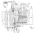
- the large rolling bearing 1 shown in FIG. 1 is typically used in a crane, whose superstructure rotatably supports it to its undercarriage. It includes an outer bearing ring 2, which has an outer toothing 3, and a inner bearing ring 4, which is formed in two parts and an upper ring 5 and a lower ring 6 comprises.
- the outer bearing ring 2 is by means of a plurality of screws 7, over the Scope of the bearing ring are distributed, attached to the flange 8.
- the inner one Bearing ring 4 is in a corresponding manner by means of a plurality of screws 7 on Attached flange 8 of the inner bearing ring 4 bearing member, wherein the screws 7 at the same time the connection of upper ring 5 and lower ring. 6 but they do not have to.
- the screws 7 extend parallel to Rotary axis of the large rolling bearing 1.
- the outer bearing ring 2 has a radially inwardly projecting Paragraph 9, at its upper and lower sides in each case a radial tread 10, 11 and on the inner peripheral surface of a circumferential tread 12 is formed is.
- the paragraph 9 jumps in a total groove-shaped, in the circumferential direction encircling recess 13 which, in the inner bearing ring 4, more precisely in the outer peripheral surface, is formed.
- the recess 13 has their upper and lower flanks radial treads 14 and 15 and at their Reason a peripheral tread 16, each of the tread 10 and 11 and 12 am Paragraph 9.
- FIG. 1 shows, run between the treads 10th and 14 or 11 and 15 cylindrical rolling elements 17 and 18, which form a thrust bearing, and between the peripheral treads 12 and 16 also cylindrical rolling elements 19, which cause a radial support and form a radial bearing.
- the rolling elements can be held in position by a cage 20 in a conventional manner become.
- the bearing gap 21 between the two bearing rings 2 and 4 can be sealed by seals 22 to the outside, so that the storage room against external influences is protected.
- the monitoring device associated with the large rolling bearing 1 comprises in the drawn embodiment four each non-contact Wegmesssensoren S1, S2, S3 and S4.
- the two displacement sensors S1 and S2 are included arranged in the interior of the inner bearing ring 4 and each extending in radial Direction. The head of the sensors S1 and S2 jumps into the bearing gap 21 before or ends at this.
- the sensors S1 and S2 key peripheral surfaces of outer bearing ring 2 from which limit the bearing gap 21 partially.
- the Wegmesssensor S1 thereby scans a cylindrical peripheral surface 23 between the two rows of rolling elements 17 and 18 from.
- the second displacement sensor S2 In contrast, it scans an oblique peripheral surface of the outer bearing ring 2, the is slightly conical, as Figure 1 shows.
- the cone angle of the conical peripheral surface 24 is preferably less than 25 °.
- the two displacement sensors S1 and S2 radial offset between the can measure both bearing rings 2 and 4, from the difference of the signals of the two Distance measuring sensors S1 and S2 in addition to the radial movements between the both bearing rings 2 and 4, the occurring axial movement are determined, through the conical peripheral surface 24, whose inclination is known.
- the two Sensors S1 and S2 are connected to the evaluation unit 25, which receives the signals on the one hand subtracted from each other, in addition to the radial movements and the To determine axial movements, and on the other hand with predetermined limits compares to determine and display wear. From the over the Sensors S1 and S2 specific radial and axial movements can tilt the game the two bearing rings 2 and 4 are determined to each other.
- Tilting play is a measure of the condition of the bearing.
- both show up Wear as well as deformation of the bearing rings as Kippspielveriere.
- To the others increase errors in the component, such as As cracks, the Kippspiel.
- the evaluation unit 25 compares this Tilting game with limits, which can be specified to the basis of this comparison To determine storage condition.
- the determination of the tilting game is also special here advantageous because an increased elongation of the screws in the axial direction increases the tilting play.
- the slewing bearings are designed differently can.
- the axial support and the radial support be effected by the same rolling elements, especially when the slewing bearings 1 is designed as a ball bearing.
- the slewing bearings 1 be designed as a double-row ball bearing. These are on the one hand in the outer Bearing ring 2 and on the other hand in the inner bearing ring 4, two in cross section formed approximately semicircular running surfaces (see Figure 3), which together the Form running surfaces for the trained as balls rolling elements 27.
- the order the sensors S1 to S4 substantially corresponds to those described above.
- the slewing bearings 1 may also be formed single row.
- the large roller bearing is a single-row ball bearing educated.
- the arrangement of the sensors S1 to S4 substantially corresponds the previously described.
Abstract
Description
Die vorliegende Erfindung betrifft eine Überwachungsvorrichtung zur Überwachung von Großwälzlagern, die zwei Lagerringe und zwischen diesen laufende Wälzkörper aufweisen, mit einem Sensor zur Erfassung von Relativbewegungen der Lagerringe zueinander.The present invention relates to a monitoring device for monitoring of slewing bearings, the two bearing rings and between them rolling elements having a sensor for detecting relative movements of the bearing rings to each other.
Großwälzlager zeichnen sich in der Regel dadurch aus, dass die Mittenbohrung des inneren Lagerrings normalerweise im wesentlichen frei bleibt und nicht auf einer im wesentlichen massiven Welle sitzt. Wenigstens einer der Lagerringe wird über parallel zur Drehachse des Lagers angeordnete Schraubverbindungen mit einem Anschlussflansch des den Lagerring tragenden Bauteils verbunden. Solche Großwälzlager werden ein- oder mehrreihig mit verschiedenen Wälzkörpern wie Kugeln, Wälzzylindern, Wälzkegeln etc. ausgeführt und finden insbesondere bei Kranen, Baggern, Tagebauabraumgeräten oder Windenergieanlagen Verwendung.Large-diameter bearings are usually characterized by the fact that the center hole the inner bearing ring normally remains substantially free and not on one essentially massive shaft sits. At least one of the bearing rings will via arranged parallel to the axis of rotation of the bearing screw with a connection flange of the bearing ring bearing member connected. Such Large-diameter bearings are single or multi-row with different rolling elements such as Spheres, Wälzzylindern, Wälzkegeln etc. executed and found in particular Cranes, excavators, open pit mining equipment or wind turbines use.
Solche Großwälzlager müssen in einem regelmäßigen Zyklus einer Inspektion unterzogen werden, bei der aus sicherheitstechnischen Gründen die Laufbahnen auf Verschleiß und Ausbrüche untersucht werden sowie die Übergangsradien auf mögliche Risse überprüft werden. Herkömmlicherweise werden diese Inspektionen bei geöffnetem Großwälzlager durchgeführt, was wiederum die Demontage des Lagers aus dem Kran erforderlich macht. Es versteht sich, dass diese Demontage des Lagers zum Zwecke der Inspektion sehr aufwendig ist und zudem den Kran für eine geraume Zeit außer Betrieb setzt.Such slewing bearings must be inspected in a regular cycle be, at the for safety reasons, the careers on Wear and breakouts are examined as well as the transition radii to possible Cracks are checked. Traditionally, these inspections are included open slewing bearing performed, which in turn dismantling the camp required from the crane. It is understood that this dismantling of the warehouse For the purpose of inspection is very complex and also the crane for a decommissioned for a long time.
Es wurde daher in jüngerer Zeit vorgeschlagen, in das Großwälzlager sogenannte Wirbelstromsensoren einzubauen, von denen ein hochfrequentes Magnetfeld ausgeht, welches in den Laufbahnen und Radien des Großwälzlagers Wirbelstrom induziert. Die entstehenden Magnetfelder werden durch Laufbahnverschleiß, Risse und dergleichen beeinflusst, so dass durch Messung des Magnetfeldes eine Aussage über den Verschleißzustand der Lagerflächen gemacht werden kann (vgl. Technische Mitteilungen Krupp, Ausgabe April 1993).It has therefore been proposed in recent times, in the large rolling bearing so-called Incorporating eddy current sensors emitting a high frequency magnetic field, which induces eddy current in the raceways and radii of the large rolling bearing. The resulting magnetic fields are due to raceway wear, cracks and the like, so that by measuring the magnetic field, a statement can be made on the wear condition of the bearing surfaces (see. Technical Information Krupp, April 1993 issue).
Weiterhin ist aus der DE 197 55 000 C1 eine Verschleißmessvorrichtung für Großwälzlager bekannt, die eine in einem Lagerring aufgenommene Sonde besitzt, die mit ihrem Ende in einen Lagerhohlraum ragt und zum gegenüberliegenden Lagerring vorspringt. In diesem ist eine Nut vorgesehen, in der der Kopf der Sonde bei verschleißfreiem Zustand des Lagers berührungslos läuft. Erleidet das Lager hingegen einen vorgegebenen Verschleiß, berührt der Sondenkopf die Oberfläche des gegenüberliegenden Lagerrings, wodurch ein Kontakt geschlossen wird und ein entsprechendes Signal erzeugt wird. Obwohl diese bekannte Verschleißmessvorrichtung übermäßigen Verschleiß auch ohne Öffnen des Großwälzlagers erkennen kann, wäre es wünschenswert, den Lagerzustand präziser angeben zu können.Furthermore, from DE 197 55 000 C1 a wear measuring device for slewing bearings known, which has a recorded in a bearing ring probe, the protrudes with its end in a bearing cavity and the opposite bearing ring projects. In this a groove is provided, in which the head of the probe at Wear-free state of the bearing without contact. Suffers the camp, however a predetermined wear, the probe head touches the surface of the opposite bearing ring, whereby a contact is closed and a corresponding signal is generated. Although this known wear measuring device detect excessive wear even without opening the large roller bearing if it is desirable to be able to specify the storage condition more precisely.
Der vorliegenden Erfindung liegt daher die Aufgabe zugrunde, eine verbesserte Überwachungsvorrichtung der eingangs genannten Art zu schaffen, die Nachteile des Standes der Technik vermeidet und letzteren in vorteilhafter Weise weiterbildet. Vorzugsweise soll eine präzisere und differenziertere Aussage über den Lagerzustand getroffen werden können. The present invention is therefore based on the object, an improved Monitoring device of the type mentioned, the disadvantages avoids the prior art and further develops the latter in an advantageous manner. Preferably, a more precise and differentiated statement about the storage condition can be taken.
Erfindungsgemäß wird diese Aufgabe durch eine Überwachungsvorrichtung gemäß Anspruch 1 gelöst. Bevorzugte Ausgestaltungen der Erfindung sind Gegenstand der abhängigen Ansprüche.According to the invention this object is achieved by a monitoring device according to Claim 1 solved. Preferred embodiments of the invention are the subject the dependent claims.
Erfindungsgemäß besitzt die Überwachungsvorrichtung also zumindest zwei berührungslose Wegmesssensoren, von denen einer zur Bestimmung von Radialbewegungen und einer zur Bestimmung von Axialbewegungen der beiden Lagerringe relativ zueinander vorgesehen ist, sowie eine mit den Wegmesssensoren verbindbare Auswerteeinheit, die die bestimmten Radial- und Axialbewegungen mit vorgegebenen Grenzwerten vergleicht und anhand des Vergleichs den Lagerzustand bestimmt. Insbesondere kann anhand der bestimmten Radial- und Axialbewegungen das Kippspiel der beiden Lagerringe überwacht bzw. bestimmt werden und mit einem vorgegebenen Grenzwert verglichen werden, wobei anhand dieses Vergleichs der Lagerzustand bestimmt und angezeigt werden kann. Das Kippspiel der Lagerringe entspricht dabei der örtlichen axialen Bewegung der sich drehenden Teile in der Momentenebene und ist ein sicheres Maß für Verschleiß, Verformung oder Fehler wie Risse und dergleichen der Lagerringe. Auch Veränderungen in den Befestigungsschrauben der Lagerringe können über das Kippspiel erfasst werden, da eine vergrößerte Schraubendehnung in axialer Richtung das Kippspiel erhöht. Vorteilhafterweise können die beiden Wegmesssensoren voneinander beabstandet angeordnet sein und unterschiedliche Abschnitte des jeweiligen Lagerrings berührungslos abtasten, so dass eine sichere Aussage über das Kippspiel des Lagers abgeleitet werden kann. Die beiden Wegmesssensoren der Überwachungsvorrichtung sowie die zugehörige Auswerteeinheit bilden sozusagen eine Kippspiel-Erfassungsvorrichtung, mit Hilfe derer das Kippspiel der Lagerringe erfasst bzw. bestimmt werden kann. Die berührungslos arbeitenden Wegmesssensoren erleiden dabei keinerlei Verschleiß. Gegenüber Ein-/Aus-Tastern erlauben die Wegmesssensoren nicht nur die Anzeige eines kritischen Lagerverschleißes, sondern vielmehr eine qualifizierte Differenzierung des Verschleißzustands dahingehend, dass angezeigt werden kann, wie weit der Verschleiß vom kritischen Verschleiß noch weg ist bzw. inwieweit Verschleiß in nennenswertem Umfang überhaupt bereits aufgetreten ist. According to the invention, the monitoring device thus has at least two non-contact Distance measuring sensors, one of which for determining radial movements and one for determining axial movements of the two bearing rings is provided relative to each other, and connectable to the Wegmesssensoren Evaluation unit, which specifies the specific radial and axial movements Limits compares and based on the comparison the storage condition certainly. In particular, based on the specific radial and axial movements the tilting clearance of the two bearing rings are monitored or determined and with are compared to a predetermined limit, based on this comparison the storage condition can be determined and displayed. The tilting game of Bearing rings corresponds to the local axial movement of the rotating Parts in the moment level and is a sure measure of wear, deformation or defects such as cracks and the like of the bearing rings. Also changes in the Fixing screws of the bearing rings can be detected by the tilting clearance, because an increased helical expansion in the axial direction increases the tilting clearance. Advantageously, the two position measuring sensors can be spaced apart from one another be arranged and different sections of the respective bearing ring contactless so that a reliable statement about the tilting play of the camp can be derived. The two displacement sensors of the monitoring device as well as the associated evaluation unit form, as it were, a tilting play detection device, with the aid of which the tilting clearance of the bearing rings is detected or can be determined. The non-contact distance measuring sensors suffer no wear. Compared with on / off buttons, the distance measuring sensors allow not just the indication of critical bearing wear, but rather a qualified differentiation of the state of wear to the effect that It can be displayed how far the wear from critical wear still is gone or to what extent wear to a significant extent at all already occured.
Um eine kompakte Anordnung der Wegmesssensoren zu erreichen, können in Weiterbildung der Erfindung beide Wegmesssensoren Bewegungen in derselben Richtung messen, so dass beide Wegmesssensoren parallel zueinander ausgerichtet werden können. Um dennoch sowohl Axial- als auch Radialbewegungen der Lagerringe bestimmen zu können, kann hierbei ein Wegmesssensor eine zu der genannten Bewegungsrichtung senkrechte Messfläche abtasten, während der andere Wegmesssensor eine zu der Bewegungsrichtung keilförmig geneigte Schrägfläche abtastet. Die Auswerteeinheit bestimmt die Bewegungen senkrecht zu der genannten einen Bewegungsrichtung aus der Differenz der beiden Sensorsignale. Bei dieser Ausführung werden also Bewegungen in einer Richtung direkt erfasst, während Bewegungen in der Richtung senkrecht hierzu indirekt erfasst werden.In order to achieve a compact arrangement of Wegmesssensoren, can in training the invention both position sensors movements in the same direction measure so that both position sensors are aligned parallel to each other can be. Nevertheless, both axial and radial movements of the bearing rings To be able to determine this, a Wegmesssensor a to the above Motion direction vertical sensing surface while the other Distance measuring sensor to the direction of movement wedge-shaped inclined inclined surface scans. The evaluation unit determines the movements perpendicular to the said a direction of movement of the difference between the two sensor signals. At this Execution, ie movements in one direction are detected directly while Movements in the direction perpendicular to this are detected indirectly.
Die beiden Wegmesssensoren sind vorzugsweise in einer gemeinsamen Ebene angeordnet, die vorzugsweise die Drehachse des Lagers enthalten kann. Die Anordnung in einer gemeinsamen Ebene schließt bei der Wegerfassung über den Umfang mögliche Ungleichmäßigkeiten in der Bewegung aus und bewirkt eine erhöhte Messgenauigkeit. Die Differenzbildung des an der Schrägfläche erzeugten Sensorsignals und des an der senkrechten Messfläche erzeugten Sensorsignals kann frei von Störeinflüssen erfolgen.The two displacement sensors are preferably in a common plane arranged, which may preferably contain the axis of rotation of the bearing. The order in a common plane closes in the path detection over the Scope out possible irregularities in the movement and causes an increased Measurement accuracy. The difference of the generated at the inclined surface Sensor signal and the sensor signal generated at the vertical measuring surface can be done free from interference.
Eine besonders geschützte und kompakte Anordnung kann dadurch erreicht werden, dass die beiden Wegmesssensoren radial ausgerichtet sind und Umfangsflächen der Lagerringe abtasten, wobei die beiden Sensoren vorzugsweise im Inneren eines Lagerrings angeordnet sind. Grundsätzlich wäre es auch denkbar, die Wegmesssensoren axial anzuordnen und Radialflächen der Lagerringe abzutasten. Die radiale Anordnung mit Abtastung von Umfangsflächen besitzt jedoch den Vorteil, dass mehr Platz zur Verfügung steht und die Wegmesssensoren nicht mit den Wälzkörpern kollidieren. Großwälzlager bilden regelmäßig Axiallager, so dass entsprechende auf radialen Lagerflächen laufende Wälzkörper vorgesehen sind. A particularly protected and compact arrangement can be achieved by that the two displacement sensors are radially aligned and peripheral surfaces scan the bearing rings, the two sensors preferably in the interior a bearing ring are arranged. In principle, it would also be conceivable, the displacement sensors to arrange axially and to scan radial surfaces of the bearing rings. The Radial arrangement with scanning peripheral surfaces has the advantage, however, that more space is available and the distance measuring sensors are not compatible with the Rolling collide. Large rolling bearings regularly form thrust bearings, so that appropriate rolling bodies running on radial bearing surfaces are provided.
Insbesondere können die beiden Sensoren im inneren Lagerring angeordnet sein und eine Innenumfangsfläche des äußeren Lagerrings abtasten, wobei der Kopf der Sensoren vorzugsweise im abgedichteten Lagerspalt des Großwälzlagers angeordnet ist. Bei Großwälzlagern für Krane ist regelmäßig der äußere Lagerring mit einer Außenverzahnung versehen, mit der ein Antriebsritzel des Drehwerks des Krans kämmt. Die Anordnung der Sensoren im inneren Lagerring besitzt dabei den Vorteil, dass die Messsensoren nicht mit der Verzahnung kollidieren.In particular, the two sensors can be arranged in the inner bearing ring and scan an inner peripheral surface of the outer race, the head of the Sensors are preferably arranged in the sealed bearing gap of the large rolling bearing is. In large rolling bearings for cranes is regularly the outer bearing ring with an external toothing provided with a drive pinion of the slewing of Krans combs. The arrangement of the sensors in the inner bearing ring has the Advantage that the measuring sensors do not collide with the toothing.
Es versteht sich jedoch, dass die Sensoranordnung auch im umgekehrten Fall Verwendung finden kann, wenn das Großwälzlager eine Innenverzahnung aufweist. In diesem Fall sind die beiden Sensoren sozusagen spiegelbildlich, vorteilhafterweise im äußeren Lagerring, angeordnet und tasten eine Außenumfangsfläche des inneren Lagerringes ab.It is understood, however, that the sensor arrangement also in the opposite case Can be used when the large roller bearing has an internal toothing. In this case, the two sensors are, so to speak, a mirror image, advantageously in the outer bearing ring, arranged and grooved an outer peripheral surface of the from inner bearing ring.
Sind beide Sensoren radial angeordnet, tastet vorteilhafterweise einer der beiden Wegsensoren eine konische Ringumfangsfläche ab, während der andere eine zylindrische Ringumfangsfläche abtastet. Die Neigung der Schrägfläche gegenüber der senkrechten Fläche, auf die der andere Sensor gerichtet ist, kann unterschiedlich gewählt werden und nach einer Ausführung der Erfindung 20° oder weniger betragen.If both sensors are arranged radially, one of the two advantageously scans Displacement sensors from a conical annular peripheral surface, while the other a cylindrical Scans annular surface. The inclination of the inclined surface opposite The vertical surface to which the other sensor is directed may vary are selected and 20 ° or less according to an embodiment of the invention be.
In Weiterbildung der Erfindung bestimmt die Überwachungsvorrichtung nicht nur im Lagerspalt das Spiel der beiden Lagerringe relativ zueinander, sondern überwacht auch Bewegungen der Lagerringe, insbesondere deren Kippspiel, außerhalb des Lagerspalts. In Weiterbildung der Erfindung kann hierzu zumindest ein weiterer berührungsloser Wegmesssensor vorgesehen sein, mit Hilfe dessen axiale Bewegungen des Lagerrings im Bereich seines Befestigungsabschnitts, insbesondere am Anschlussflansch, an dem der Lagerring befestigt ist, bestimmt werden kann. Die Auswerteeinheit vergleicht die mit Hilfe des Wegmesssensors bestimmten Bewegungen des Lagerrings mit vorgegebenen Grenzwerten und kann in Abhängigkeit des Vergleichs den Zustand der Befestigung, insbesondere der Schraubenbefestigung des Lagerrings am Anschlussflansch, bestimmen und anzeigen. In a further development of the invention, the monitoring device determines not only in Lagerspalt the game of the two bearing rings relative to each other, but monitors also movements of the bearing rings, in particular their tilting play, outside the Bearing gap. In a further development of the invention, at least one further non-contact Wegmesssensor be provided, with the help of which axial movements the bearing ring in the region of its attachment portion, in particular on Connection flange to which the bearing ring is attached, can be determined. The The evaluation unit compares the movements determined with the aid of the displacement sensor of the bearing ring with predetermined limits and can be dependent the comparison of the state of attachment, in particular the screw fastening of the bearing ring on the connecting flange, determine and display.
Der genannte weitere Wegmesssensor kann dabei die axialen Bewegungen des Lagerrings außerhalb des Lagerspalts direkt messen. In diesem Fall ist der Wegmesssensor in axialer Richtung ausgerichtet und auf eine radiale Fläche des Lagerrings bzw. eines damit verbundenen Ringteils gerichtet.The said further displacement measuring sensor can be the axial movements of the Measure the bearing ring directly outside the bearing gap. In this case, the position sensor is aligned in the axial direction and on a radial surface of the bearing ring or an associated ring member directed.
Alternativ oder zusätzlich kann ein in radialer Richtung ausgerichteter Wegmesssensor vorgesehen sein, der auf eine zur radialen Richtung spitzwinklig geneigten Schrägfläche Bewegungen des Lagerrings in radialer Richtung misst. Über die spitzwinklig geneigte Schrägfläche kann aus den erfassten Radialbewegungen die entsprechenden Axialbewegungen des Lagerrings relativ zum Anschlussflansch von der Auswerteeinheit bestimmt werden.Alternatively or additionally, a distance-measuring sensor aligned in the radial direction be provided, which is inclined at an acute angle to the radial direction Inclined surface Measures movements of the bearing ring in the radial direction. About the Angled obliquely inclined surface can from the detected radial movements corresponding axial movements of the bearing ring relative to the connection flange be determined by the evaluation.
Die Erfindung wird nachfolgend anhand bevorzugter Ausführungsbeispiele und zugehöriger Zeichnungen näher erläutert. In den Zeichnungen zeigen:
- Fig. 1:
- einen ausschnittsweisen Axialschnitt durch ein Großwälzlager mit einer diesem zugeordneten Überwachungsvorrichtung nach einer bevorzugten Ausführung der Erfindung,
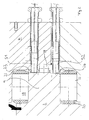
- Fig. 2:
- eine vergrößerte, ausschnittsweise Axialschnittansicht eines Großwälzlagers ähnlich Fig. 1 mit einer alternativen Anordnung der Wegmesssensoren S1 und S2,
- Fig. 3:
- einen Axialschnitt durch ein Großwälzlager mit einer zugeordneten Überwachungsvorrichtung nach einer weiteren Ausführung der Erfindung, und
- Fig. 4:
- einen ausschnittsweisen Axialschnitt durch ein Großwälzlager mit einer diesem zugeordneten Überwachungsvorrichtung nach einer weiteren bevorzugten Ausführung der Erfindung.
- Fig. 1:
- a fragmentary axial section through a slewing bearing with a monitoring device associated therewith according to a preferred embodiment of the invention,
- Fig. 2:
- 1 is an enlarged, partial axial sectional view of a slewing bearing similar to FIG. 1 with an alternative arrangement of the displacement measuring sensors S1 and S2, FIG.
- 3:
- an axial section through a slewing bearing with an associated monitoring device according to a further embodiment of the invention, and
- 4:
- a partial axial section through a slewing bearing with a monitoring device associated therewith according to a further preferred embodiment of the invention.
Das in Figur 1 gezeigte Großwälzlager 1 findet typischerweise in einem Kran Verwendung,
dessen Oberwagen es drehbar zu dessen Unterwagen lagert. Es umfasst
einen äußeren Lagerring 2, der eine Außenverzahnung 3 aufweist, sowie einen
inneren Lagerring 4, der zweiteilig ausgebildet ist und einen Oberring 5 und
einen Unterring 6 umfasst.The large rolling bearing 1 shown in FIG. 1 is typically used in a crane,
whose superstructure rotatably supports it to its undercarriage. It includes
an
Der äußere Lagerring 2 ist mittels einer Vielzahl von Schrauben 7, die über den
Umfang des Lagerrings verteilt sind, am Anschlussflansch 8 befestigt. Der innere
Lagerring 4 ist in entsprechender Weise mittels einer Vielzahl von Schrauben 7 am
Anschlussflansch 8 des den inneren Lagerring 4 tragenden Bauteils befestigt, wobei
die Schrauben 7 gleichzeitig der Verbindung von Oberring 5 und Unterring 6
dienen können, jedoch nicht müssen. Die Schrauben 7 erstrecken sich parallel zur
Drehachse des Großwälzlagers 1.The
Wie Figur 1 zeigt, besitzt der äußere Lagerring 2 einen radial nach innen vorspringenden
Absatz 9, an dessen Ober- und Unterseiten jeweils eine radiale Lauffläche
10, 11 und an dessen Innenumfangsfläche eine Umfangslauffläche 12 ausgebildet
ist. Der Absatz 9 springt dabei in eine insgesamt nutförmige, in Umfangsrichtung
umlaufende Ausnehmung 13 vor, die in dem inneren Lagerring 4, genauer gesagt
in dessen äußeren Umfangsfläche, ausgebildet ist. Die Ausnehmung 13 besitzt an
ihren oberen und unteren Flanken radiale Laufflächen 14 und 15 sowie an ihrem
Grund eine Umfangslauffläche 16, die jeweils den Lauffläche 10 und 11 bzw. 12 am
Absatz 9 gegenüberliegen. Wie Figur 1 zeigt, laufen zwischen den Laufflächen 10
und 14 bzw. 11 und 15 zylindrische Wälzkörper 17 und 18, die ein Axiallager bilden,
sowie zwischen den Umfangslaufflächen 12 und 16 ebenfalls zylindrische Wälzkörper
19, die eine radiale Abstützung bewirken und ein Radiallager bilden. Die Wälzkörper
können in an sich bekannter Weise durch einen Käfig 20 in Position gehalten
werden. Der Lagerspalt 21 zwischen den beiden Lagerringen 2 und 4 kann
durch Dichtungen 22 nach außen hin abgedichtet sein, so dass der Lagerraum gegen
äußere Einflüsse geschützt ist. As Figure 1 shows, the
Die dem Großwälzlager 1 zugeordnete Überwachungsvorrichtung umfasst in der
gezeichneten Ausführungsform vier jeweils berührungslos arbeitende Wegmesssensoren
S1, S2, S3 und S4. Die beiden Wegmesssensoren S1 und S2 sind dabei
im Inneren des inneren Lagerrings 4 angeordnet und erstrecken sich jeweils in radialer
Richtung. Der Kopf der Sensoren S1 und S2 springt dabei in den Lagerspalt
21 vor bzw. endet an diesem. Die Sensoren S1 und S2 tasten Umfangsflächen des
äußeren Lagerrings 2 ab, die den Lagerspalt 21 partiell begrenzen. Wie Figur 1
zeigt, tastet der Wegmesssensor S1 dabei eine zylindrische Umfangsfläche 23 zwischen
den beiden Wälzkörperreihen 17 und 18 ab. Der zweite Wegmesssensor S2
tastet hingegen eine schräge Umfangsfläche des äußeren Lagerrings 2 ab, die
leicht konisch ausgebildet ist, wie Figur 1 zeigt. Der Kegelwinkel der konischen Umfangsfläche
24 beträgt vorzugsweise weniger als 25°.The monitoring device associated with the large rolling bearing 1 comprises in the
drawn embodiment four each non-contact Wegmesssensoren
S1, S2, S3 and S4. The two displacement sensors S1 and S2 are included
arranged in the interior of the
Obwohl die beiden Wegmesssensoren S1 und S2 radialen Versatz zwischen den
beiden Lagerringen 2 und 4 messen, kann aus der Differenz der Signale der beiden
Wegmesssensoren S1 und S2 zusätzlich zu den Radialbewegungen zwischen den
beiden Lagerringen 2 und 4 auch die auftretende Axialbewegung bestimmt werden,
und zwar über die kegelige Umfangsfläche 24, deren Neigung bekannt ist. Die beiden
Sensoren S1 und S2 sind mit der Auswerteeinheit 25 verbunden, die die Signale
einerseits voneinander subtrahiert, um neben den Radialbewegungen auch die
Axialbewegungen zu bestimmen, und andererseits mit vorgegebenen Grenzwerten
vergleicht, um Verschleiß zu bestimmen und anzeigen zu können. Aus den über die
Sensoren S1 und S2 bestimmten Radial- und Axialbewegungen kann das Kippspiel
der beiden Lagerringe 2 und 4 zueinander bestimmt werden. Insbesondere dieses
Kippspiel ist ein Maß für den Zustand des Lagers. Einerseits zeigen sich sowohl
Verschleiß wie auch Verformung der Lagerringe als Kippspielvergrößerungen. Zum
anderen erhöhen Fehler im Bauteil, wie z. B. Risse, das Kippspiel.Although the two displacement sensors S1 and S2 radial offset between the
can measure both bearing
Wie Figur 1 zeigt, können weiterhin auch außerhalb des Lagerspalts 21 angeordnete
Wegmesssensoren S3 und S4 vorgesehen sein. Auch hier erfasst einer der
Wegmesssensoren Bewegungen einer zur Sensorrichtung senkrecht stehenden
Fläche, während der andere Sensor Bewegungen einer Schrägfläche erfasst. Der
Sensor S4 ist axial, d.h. parallel zur Drehachse des Großwälzlagers 1 angeordnet
und erfasst unmittelbar Axialbewegungen des äußeren Lagerrings 2 im Bereich der
darin eingeschraubten Schrauben 7. Der Wegmesssensor S3 hingegen ist radial
angeordnet und erfasst radiale Bewegungen der kegeligen Innenumfangsfläche 26
des den äußeren Lagerring 2 haltenden Lagerflansches. Auch hier kann in der beschriebenen
Weise durch Differenzbildung zwischen den beiden Sensorsignalen
zusätzlich zu dem unmittelbar erfassten Axialspiel auch das Radialspiel erfasst
werden. Hieraus kann in Verbindung mit der bekannten Geometrie der Sensoranordnung
das Kippspiel bestimmt werden. Die Auswerteeinheit 25 vergleicht dieses
Kippspiel mit Grenzwerten, die vorgebbar sind, um anhand dieses Vergleichs den
Lagerzustand zu bestimmen. Die Bestimmung des Kippspiels ist auch hier besonders
vorteilhaft, da eine vergrößerte Dehnung der Schrauben in axialer Richtung
das Kippspiel vergrößert.As Figure 1 shows, can continue to be arranged outside the
Es versteht sich, dass die in Figur 1 gezeigte Anordnung der Sensoren auch abgeändert
werden kann. Wie Figur 2 zeigt, können beispielsweise die beiden Sensoren
S1 und S2 die Innenumfangsfläche des radial nach innen vorspringenden Absatzes
9 abtasten. Auch hier tastet der Sensor S1 eine zylindrische Umfangsfläche ab,
während der Sensor S2 eine kegelige Umfangsfläche abtastet. Dies ermöglicht in
der beschriebenen Weise neben der Bestimmung von Radialspiel auch die Bestimmung
von Axialspiel, woraus wiederum das Kippspiel bestimmbar ist und mit
entsprechenden Grenzwerten vergleichbar ist.It is understood that the arrangement of the sensors shown in Figure 1 also changed
can be. As Figure 2 shows, for example, the two sensors
S1 and S2, the inner peripheral surface of the radially inwardly projecting
Weiterhin versteht es sich, dass das Großwälzlager verschieden ausgebildet sein
kann. Wie Figur 3 zeigt, kann die axiale Abstützung und die radiale Abstützung
durch dieselben Wälzkörper bewirkt werden, insbesondere dann, wenn das Großwälzlager
1 als Kugellager ausgebildet ist. Wie Figur 3 zeigt, kann das Großwälzlager
1 als zweireihiges Kugellager ausgebildet sein. Hierzu sind einerseits im äußeren
Lagerring 2 und andererseits im inneren Lagerring 4 jeweils zwei im Querschnitt
etwa halbkreisförmige Laufflächen ausgebildet (vgl. Figur 3), die zusammen die
Laufflächen für die als Kugeln ausgebildete Wälzkörper 27 bilden. Die Anordnung
der Sensoren S1 bis S4 entspricht im wesentlichen der zuvor beschriebenen. Furthermore, it is understood that the slewing bearings are designed differently
can. As Figure 3 shows, the axial support and the radial support
be effected by the same rolling elements, especially when the slewing bearings
1 is designed as a ball bearing. As Figure 3 shows, the slewing bearings
1 be designed as a double-row ball bearing. These are on the one hand in the
Wie Figur 4 zeigt, kann das Großwälzlager 1 auch einreihig ausgebildet sein. In der in Figur 4 gezeichneten Ausführung ist das Großwälzlager als einreihiges Kugellager ausgebildet. Die Anordnung der Sensoren S1 bis S4 entspricht im wesentlichen der zuvor beschriebenen.As Figure 4 shows, the slewing bearings 1 may also be formed single row. In the drawn in Figure 4 embodiment, the large roller bearing is a single-row ball bearing educated. The arrangement of the sensors S1 to S4 substantially corresponds the previously described.
Claims (12)
Applications Claiming Priority (2)
| Application Number | Priority Date | Filing Date | Title |
|---|---|---|---|
| DE20316544U | 2003-10-28 | ||
| DE20316544U DE20316544U1 (en) | 2003-10-28 | 2003-10-28 | Monitoring device for monitoring large-diameter bearings |
Publications (3)
| Publication Number | Publication Date |
|---|---|
| EP1528356A2 true EP1528356A2 (en) | 2005-05-04 |
| EP1528356A3 EP1528356A3 (en) | 2006-03-01 |
| EP1528356B1 EP1528356B1 (en) | 2015-01-28 |
Family
ID=34306478
Family Applications (1)
| Application Number | Title | Priority Date | Filing Date |
|---|---|---|---|
| EP04025540.8A Active EP1528356B1 (en) | 2003-10-28 | 2004-10-27 | Apparatus for monitoring of large roller bearings |
Country Status (2)
| Country | Link |
|---|---|
| EP (1) | EP1528356B1 (en) |
| DE (1) | DE20316544U1 (en) |
Cited By (17)
| Publication number | Priority date | Publication date | Assignee | Title |
|---|---|---|---|---|
| CN102072259A (en) * | 2011-01-24 | 2011-05-25 | 南京工大数控科技有限公司 | Intelligent slewing bearing with implanted sensors |
| EP2290235A3 (en) * | 2009-08-28 | 2012-01-11 | PRÜFTECHNIK Dieter Busch AG | Device and method for detecting the loading of pivoted rotor blades |
| EP2532904A3 (en) * | 2005-05-31 | 2012-12-19 | Mitsubishi Heavy Industries | Structure of slewing ring bearing |
| DE102012024269A1 (en) * | 2012-12-12 | 2014-06-12 | Imo Holding Gmbh | Moment bearing with distance sensor |
| CN106979755A (en) * | 2017-03-31 | 2017-07-25 | 武汉理工大学 | Auto pump bearing axial play automatic measuring instrument |
| WO2018041702A1 (en) * | 2016-08-30 | 2018-03-08 | Thyssenkrupp Rothe Erde Gmbh | Bearing and method for monitoring wear and/or measuring a load |
| CN109470192A (en) * | 2018-12-18 | 2019-03-15 | 南京磁谷科技有限公司 | A kind of mounting structure of electromagnetic bearing axial sensor |
| CN109915492A (en) * | 2019-04-23 | 2019-06-21 | 中铁工程服务有限公司 | A kind of main bearing of shield machine monitoring device |
| EP3483581B1 (en) | 2017-11-08 | 2020-02-26 | Eolotec GmbH | Method and device for monitoring a bearing clearance of rolling bearings |
| US10975908B1 (en) | 2019-10-29 | 2021-04-13 | Schaeffler Monitoring Services Gmbh | Method and device for monitoring a bearing clearance of roller bearings |
| CN112709756A (en) * | 2019-10-24 | 2021-04-27 | 斯凯孚公司 | Rolling bearing with ultrasonic distance sensor |
| DE102020206785A1 (en) | 2020-05-29 | 2021-12-02 | Thyssenkrupp Ag | Rolling bearings with a sensor and assembly tool |
| CN114033794A (en) * | 2021-11-16 | 2022-02-11 | 武汉理工大学 | Slewing bearing running state on-line monitoring device |
| US20220128096A1 (en) * | 2020-10-26 | 2022-04-28 | Aktiebolaget Skf | Rolling bearing assembly |
| CN114902019A (en) * | 2020-01-03 | 2022-08-12 | 蒂森克虏伯罗特艾德德国有限公司 | Rolling bearing with positioning device |
| US20220364605A1 (en) * | 2020-02-11 | 2022-11-17 | Oliver Born | Rolling bearing with monitoring device |
| WO2023131540A1 (en) * | 2022-01-10 | 2023-07-13 | Aktiebolaget Skf | Rolling bearing assembly |
Families Citing this family (20)
| Publication number | Priority date | Publication date | Assignee | Title |
|---|---|---|---|---|
| DE102004052598A1 (en) * | 2004-10-29 | 2006-05-04 | Aktiebolaget Skf | Wind turbine |
| WO2007112748A2 (en) * | 2006-04-02 | 2007-10-11 | Vestas Wind Systems A/S | A pitch bearing for a wind turbine, a wind turbine and a method for servicing a bearing |
| DE202007002609U1 (en) * | 2007-02-19 | 2008-04-03 | Landwehr, Markus | rotary joint |
| DE102007013160B4 (en) | 2007-03-20 | 2008-12-04 | ThyssenKrupp Fördertechnik GmbH | Method and device for controlling the raceways of slewing bearings |
| DE102007032972B4 (en) * | 2007-07-16 | 2015-08-06 | Knorr-Bremse Systeme für Nutzfahrzeuge GmbH | Measuring device and method for detecting an axial displacement of a shaft |
| DE102008008727A1 (en) | 2008-02-12 | 2009-08-13 | Schaeffler Kg | Bearing, particularly rolling or sliding bearing, has position sensor to supply correspondingly similar signals to relative position of both bearing parts, and is comprised of potentiometer, which has resistance path and position finger |
| DE102008026081A1 (en) | 2008-05-30 | 2009-12-31 | Schaeffler Kg | Storage device with position sensor |
| US8002472B2 (en) * | 2008-06-30 | 2011-08-23 | Nucor Corporation | Slew bearing system |
| DE102008046357A1 (en) * | 2008-09-09 | 2010-03-11 | Schaeffler Kg | Sensor arrangement for determining a parameter for the wear of a rolling bearing and wind turbine |
| DE102012211566A1 (en) * | 2012-07-03 | 2014-01-09 | Wobben Properties Gmbh | Monitored component connection, wind turbine, method for monitoring a component connection to an unwanted release of the component connection in the connected state |
| EP2743522A1 (en) * | 2012-12-12 | 2014-06-18 | IMO Holding GmbH | Torque or (large) roller bearing or rotary connection with distance sensor (s) |
| DE112013007193A5 (en) | 2013-06-25 | 2016-03-03 | Imo Holding Gmbh | Spring pressure system for bearing assembly and bearing assembly equipped therewith |
| DE102013010500B4 (en) | 2013-06-25 | 2018-12-27 | Imo Holding Gmbh | With spring pressure system equipped bearing assembly |
| DE102018200573A1 (en) * | 2018-01-15 | 2019-07-18 | Zf Friedrichshafen Ag | Part-turn actuator with condition monitoring |
| DE102019217788A1 (en) * | 2019-11-19 | 2021-05-20 | Aktiebolaget Skf | Bearings with distance sensors and conical groove |
| DE102019217789A1 (en) * | 2019-11-19 | 2021-05-20 | Aktiebolaget Skf | Bearings with distance sensors and conical grooves |
| DE102019218144A1 (en) | 2019-11-25 | 2021-05-27 | Aktiebolaget Skf | Bearings with a distance measuring system and associated groove |
| DE102019218143A1 (en) * | 2019-11-25 | 2021-05-27 | Aktiebolaget Skf | Warehouse with a sliding target and associated sensor |
| DE102021100222A1 (en) | 2021-01-08 | 2022-07-14 | Schaeffler Technologies AG & Co. KG | Process for the production of different variants of a series of round axle bearings |
| NL2032602B1 (en) | 2022-07-26 | 2024-02-05 | Itrec Bv | Slew bearing with load monitoring |
Citations (4)
| Publication number | Priority date | Publication date | Assignee | Title |
|---|---|---|---|---|
| US5336996A (en) | 1992-08-21 | 1994-08-09 | The Duriron Company, Inc. | Hall effect monitoring of wear of bearing supporting a rotor within a stationary housing |
| DE19755000C1 (en) | 1997-12-11 | 1999-03-04 | Krupp Ag Hoesch Krupp | Wear measuring device for roller bearing |
| US5955880A (en) | 1996-12-05 | 1999-09-21 | Beam; Palmer H. | Sealless pump rotor position and bearing monitor |
| DE10107067A1 (en) | 2000-02-14 | 2001-08-16 | Teikoku Denki Seisakusho Hyogo | Axial wear indicator device for an encapsulated motor for pump or chemical industry use, enabling bearing wear to be readily detected and indicated so that a user knows when wear has started to occur |
Family Cites Families (4)
| Publication number | Priority date | Publication date | Assignee | Title |
|---|---|---|---|---|
| NL8503517A (en) * | 1985-12-19 | 1987-07-16 | Skf Ind Trading & Dev | SWING CIRCLE. |
| FR2680874B1 (en) * | 1991-08-26 | 1995-03-24 | Roulements Soc Nouvelle | MAGNETIC CIRCUITS. |
| DE4128807A1 (en) * | 1991-08-30 | 1993-03-04 | Hoesch Ag | DEVICE FOR MONITORING ROLLER BEARINGS |
| DE19919007B4 (en) * | 1999-04-27 | 2005-03-24 | Fag Kugelfischer Ag | Device for measuring bearing data |
-
2003
- 2003-10-28 DE DE20316544U patent/DE20316544U1/en not_active Expired - Lifetime
-
2004
- 2004-10-27 EP EP04025540.8A patent/EP1528356B1/en active Active
Patent Citations (4)
| Publication number | Priority date | Publication date | Assignee | Title |
|---|---|---|---|---|
| US5336996A (en) | 1992-08-21 | 1994-08-09 | The Duriron Company, Inc. | Hall effect monitoring of wear of bearing supporting a rotor within a stationary housing |
| US5955880A (en) | 1996-12-05 | 1999-09-21 | Beam; Palmer H. | Sealless pump rotor position and bearing monitor |
| DE19755000C1 (en) | 1997-12-11 | 1999-03-04 | Krupp Ag Hoesch Krupp | Wear measuring device for roller bearing |
| DE10107067A1 (en) | 2000-02-14 | 2001-08-16 | Teikoku Denki Seisakusho Hyogo | Axial wear indicator device for an encapsulated motor for pump or chemical industry use, enabling bearing wear to be readily detected and indicated so that a user knows when wear has started to occur |
Non-Patent Citations (1)
| Title |
|---|
| KRUPP: "Technische Mitteilungen", April 1993 |
Cited By (27)
| Publication number | Priority date | Publication date | Assignee | Title |
|---|---|---|---|---|
| EP2532904A3 (en) * | 2005-05-31 | 2012-12-19 | Mitsubishi Heavy Industries | Structure of slewing ring bearing |
| EP2290235A3 (en) * | 2009-08-28 | 2012-01-11 | PRÜFTECHNIK Dieter Busch AG | Device and method for detecting the loading of pivoted rotor blades |
| CN102072259A (en) * | 2011-01-24 | 2011-05-25 | 南京工大数控科技有限公司 | Intelligent slewing bearing with implanted sensors |
| DE102012024269A1 (en) * | 2012-12-12 | 2014-06-12 | Imo Holding Gmbh | Moment bearing with distance sensor |
| US10738826B2 (en) | 2016-08-30 | 2020-08-11 | Thyssenkrupp Rothe Erde Gmbh | Bearing and method for monitoring wear and/or measuring a load |
| WO2018041702A1 (en) * | 2016-08-30 | 2018-03-08 | Thyssenkrupp Rothe Erde Gmbh | Bearing and method for monitoring wear and/or measuring a load |
| CN109690097A (en) * | 2016-08-30 | 2019-04-26 | 蒂森克虏伯罗特艾德有限公司 | Bearing and for monitor abrasion and/or measurement load method |
| CN109690097B (en) * | 2016-08-30 | 2020-12-11 | 蒂森克虏伯罗特艾德有限公司 | Bearing and method for monitoring wear and/or measuring load |
| US20190195278A1 (en) * | 2016-08-30 | 2019-06-27 | Thyssenkrupp Rothe Erde Gmbh | Bearing and method for monitoring wear and/or measuring a load |
| CN106979755A (en) * | 2017-03-31 | 2017-07-25 | 武汉理工大学 | Auto pump bearing axial play automatic measuring instrument |
| EP3483581B1 (en) | 2017-11-08 | 2020-02-26 | Eolotec GmbH | Method and device for monitoring a bearing clearance of rolling bearings |
| CN109470192A (en) * | 2018-12-18 | 2019-03-15 | 南京磁谷科技有限公司 | A kind of mounting structure of electromagnetic bearing axial sensor |
| CN109915492A (en) * | 2019-04-23 | 2019-06-21 | 中铁工程服务有限公司 | A kind of main bearing of shield machine monitoring device |
| CN112709756A (en) * | 2019-10-24 | 2021-04-27 | 斯凯孚公司 | Rolling bearing with ultrasonic distance sensor |
| US10975908B1 (en) | 2019-10-29 | 2021-04-13 | Schaeffler Monitoring Services Gmbh | Method and device for monitoring a bearing clearance of roller bearings |
| CN114902019A (en) * | 2020-01-03 | 2022-08-12 | 蒂森克虏伯罗特艾德德国有限公司 | Rolling bearing with positioning device |
| CN114902019B (en) * | 2020-01-03 | 2024-03-08 | 蒂森克虏伯罗特艾德德国有限公司 | Rolling bearing with positioning device |
| US20220364605A1 (en) * | 2020-02-11 | 2022-11-17 | Oliver Born | Rolling bearing with monitoring device |
| DE102020206785A1 (en) | 2020-05-29 | 2021-12-02 | Thyssenkrupp Ag | Rolling bearings with a sensor and assembly tool |
| DE102020206785B4 (en) | 2020-05-29 | 2024-02-15 | Thyssenkrupp Ag | Rolling bearing with a sensor and assembly tool |
| AT524361A3 (en) * | 2020-10-26 | 2022-07-15 | Skf Ab | roller bearing arrangement |
| US20220128096A1 (en) * | 2020-10-26 | 2022-04-28 | Aktiebolaget Skf | Rolling bearing assembly |
| US11624407B2 (en) * | 2020-10-26 | 2023-04-11 | Aktiebolaget Skf | Rolling bearing assembly |
| AT524361B1 (en) * | 2020-10-26 | 2023-07-15 | Skf Ab | roller bearing arrangement |
| CN114033794B (en) * | 2021-11-16 | 2022-11-15 | 武汉理工大学 | Slewing bearing running state on-line monitoring device |
| CN114033794A (en) * | 2021-11-16 | 2022-02-11 | 武汉理工大学 | Slewing bearing running state on-line monitoring device |
| WO2023131540A1 (en) * | 2022-01-10 | 2023-07-13 | Aktiebolaget Skf | Rolling bearing assembly |
Also Published As
| Publication number | Publication date |
|---|---|
| DE20316544U1 (en) | 2005-03-10 |
| EP1528356A3 (en) | 2006-03-01 |
| EP1528356B1 (en) | 2015-01-28 |
Similar Documents
| Publication | Publication Date | Title |
|---|---|---|
| EP1528356B1 (en) | Apparatus for monitoring of large roller bearings | |
| EP3507513B1 (en) | Bearing and method to monitor wear and/or load measuring | |
| EP0922870B1 (en) | Wear measuring device for large rolling bearings | |
| DE4219318C2 (en) | Method and device for determining the contact angle of ball bearings | |
| EP2276658B1 (en) | Measurement bearing, in particular for a wheel set of a rail vehicle | |
| EP1924834B1 (en) | Sensor arrangement | |
| DE102006028294A1 (en) | Radial bearing assembly, has bearing ring, which is arranged with radial play in or on assigned element and this counterpart is centered or held by radial spring clamping ring assembly | |
| DE3927077A1 (en) | MEDIUM-FREE WHOLE BEARING | |
| DE102017207814A1 (en) | Swivel bearing with seal arrangement | |
| DE2947937C2 (en) | Method and device for determining roller bearing damage | |
| WO2014090347A1 (en) | Moment or rolling bearing arrangement having sensor system | |
| EP1972918A2 (en) | Method and device for inspecting the path of large roller bearings | |
| EP4081719B1 (en) | Rolling bearing with monitoring device | |
| EP2743522A1 (en) | Torque or (large) roller bearing or rotary connection with distance sensor (s) | |
| DE102019217789A1 (en) | Bearings with distance sensors and conical grooves | |
| DE19713688B4 (en) | Rolling bearing with a displacement measuring device | |
| AT524361B1 (en) | roller bearing arrangement | |
| DE102022206188A1 (en) | System for determining wear of a bearing and associated method | |
| DE102019218884B4 (en) | Slewing bearings and methods for measuring wear | |
| DE102010005511A1 (en) | Roller bearing arrangement for use in wind power plant, has rollers held in bolt cage and comprising axial bore, sensors arranged in housing member and responding to proximity of releasable bolts, which are inserted into bore | |
| DE102010005476B4 (en) | Method and device for detecting the load in a rolling bearing | |
| EP3339853B1 (en) | Method for acoustically examining a path of travel of a main body of a large scale roller bearing | |
| DE102014223219A1 (en) | Bearing arrangement with a force sensor and Sensorwälzkörper for such a bearing assembly | |
| DE102004054410A1 (en) | Sensor arrangement for self-aligning bearing, has strain gauges arranged in slots of outer ring of bearing, where gauges overrun at different time periods due to tangential deviation of inner ring of bearing relative to outer ring | |
| DE102022200165A1 (en) | roller bearing arrangement |
Legal Events
| Date | Code | Title | Description |
|---|---|---|---|
| PUAI | Public reference made under article 153(3) epc to a published international application that has entered the european phase |
Free format text: ORIGINAL CODE: 0009012 |
|
| AK | Designated contracting states |
Kind code of ref document: A2 Designated state(s): AT BE BG CH CY CZ DE DK EE ES FI FR GB GR HU IE IT LI LU MC NL PL PT RO SE SI SK TR |
|
| AX | Request for extension of the european patent |
Extension state: AL HR LT LV MK |
|
| PUAL | Search report despatched |
Free format text: ORIGINAL CODE: 0009013 |
|
| AK | Designated contracting states |
Kind code of ref document: A3 Designated state(s): AT BE BG CH CY CZ DE DK EE ES FI FR GB GR HU IE IT LI LU MC NL PL PT RO SE SI SK TR |
|
| AX | Request for extension of the european patent |
Extension state: AL HR LT LV MK |
|
| RIC1 | Information provided on ipc code assigned before grant |
Ipc: F16C 19/52 20060101ALI20060111BHEP Ipc: G01B 21/16 20060101AFI20050120BHEP Ipc: G01B 11/14 20060101ALI20060111BHEP Ipc: G01M 13/04 20060101ALI20060111BHEP Ipc: G01B 7/14 20060101ALI20060111BHEP |
|
| 17P | Request for examination filed |
Effective date: 20060725 |
|
| AKX | Designation fees paid |
Designated state(s): AT BE BG CH CY CZ DE DK EE ES FI FR GB GR HU IE IT LI LU MC NL PL PT RO SE SI SK TR |
|
| RAP1 | Party data changed (applicant data changed or rights of an application transferred) |
Owner name: LIEBHERR-COMPONENTS BIBERACH GMBH |
|
| 17Q | First examination report despatched |
Effective date: 20120928 |
|
| GRAP | Despatch of communication of intention to grant a patent |
Free format text: ORIGINAL CODE: EPIDOSNIGR1 |
|
| INTG | Intention to grant announced |
Effective date: 20140916 |
|
| GRAS | Grant fee paid |
Free format text: ORIGINAL CODE: EPIDOSNIGR3 |
|
| GRAA | (expected) grant |
Free format text: ORIGINAL CODE: 0009210 |
|
| AK | Designated contracting states |
Kind code of ref document: B1 Designated state(s): AT BE BG CH CY CZ DE DK EE ES FI FR GB GR HU IE IT LI LU MC NL PL PT RO SE SI SK TR |
|
| REG | Reference to a national code |
Ref country code: GB Ref legal event code: FG4D Free format text: NOT ENGLISH |
|
| REG | Reference to a national code |
Ref country code: CH Ref legal event code: EP |
|
| REG | Reference to a national code |
Ref country code: IE Ref legal event code: FG4D Free format text: LANGUAGE OF EP DOCUMENT: GERMAN |
|
| REG | Reference to a national code |
Ref country code: DE Ref legal event code: R096 Ref document number: 502004014818 Country of ref document: DE Effective date: 20150305 |
|
| REG | Reference to a national code |
Ref country code: AT Ref legal event code: REF Ref document number: 708419 Country of ref document: AT Kind code of ref document: T Effective date: 20150315 |
|
| REG | Reference to a national code |
Ref country code: NL Ref legal event code: T3 |
|
| PG25 | Lapsed in a contracting state [announced via postgrant information from national office to epo] |
Ref country code: FI Free format text: LAPSE BECAUSE OF FAILURE TO SUBMIT A TRANSLATION OF THE DESCRIPTION OR TO PAY THE FEE WITHIN THE PRESCRIBED TIME-LIMIT Effective date: 20150128 Ref country code: BG Free format text: LAPSE BECAUSE OF FAILURE TO SUBMIT A TRANSLATION OF THE DESCRIPTION OR TO PAY THE FEE WITHIN THE PRESCRIBED TIME-LIMIT Effective date: 20150428 Ref country code: SE Free format text: LAPSE BECAUSE OF FAILURE TO SUBMIT A TRANSLATION OF THE DESCRIPTION OR TO PAY THE FEE WITHIN THE PRESCRIBED TIME-LIMIT Effective date: 20150128 Ref country code: ES Free format text: LAPSE BECAUSE OF FAILURE TO SUBMIT A TRANSLATION OF THE DESCRIPTION OR TO PAY THE FEE WITHIN THE PRESCRIBED TIME-LIMIT Effective date: 20150128 |
|
| PG25 | Lapsed in a contracting state [announced via postgrant information from national office to epo] |
Ref country code: PL Free format text: LAPSE BECAUSE OF FAILURE TO SUBMIT A TRANSLATION OF THE DESCRIPTION OR TO PAY THE FEE WITHIN THE PRESCRIBED TIME-LIMIT Effective date: 20150128 Ref country code: GR Free format text: LAPSE BECAUSE OF FAILURE TO SUBMIT A TRANSLATION OF THE DESCRIPTION OR TO PAY THE FEE WITHIN THE PRESCRIBED TIME-LIMIT Effective date: 20150429 |
|
| REG | Reference to a national code |
Ref country code: FR Ref legal event code: PLFP Year of fee payment: 12 |
|
| REG | Reference to a national code |
Ref country code: DE Ref legal event code: R097 Ref document number: 502004014818 Country of ref document: DE |
|
| PG25 | Lapsed in a contracting state [announced via postgrant information from national office to epo] |
Ref country code: RO Free format text: LAPSE BECAUSE OF FAILURE TO SUBMIT A TRANSLATION OF THE DESCRIPTION OR TO PAY THE FEE WITHIN THE PRESCRIBED TIME-LIMIT Effective date: 20150128 Ref country code: CZ Free format text: LAPSE BECAUSE OF FAILURE TO SUBMIT A TRANSLATION OF THE DESCRIPTION OR TO PAY THE FEE WITHIN THE PRESCRIBED TIME-LIMIT Effective date: 20150128 Ref country code: EE Free format text: LAPSE BECAUSE OF FAILURE TO SUBMIT A TRANSLATION OF THE DESCRIPTION OR TO PAY THE FEE WITHIN THE PRESCRIBED TIME-LIMIT Effective date: 20150128 Ref country code: SK Free format text: LAPSE BECAUSE OF FAILURE TO SUBMIT A TRANSLATION OF THE DESCRIPTION OR TO PAY THE FEE WITHIN THE PRESCRIBED TIME-LIMIT Effective date: 20150128 Ref country code: DK Free format text: LAPSE BECAUSE OF FAILURE TO SUBMIT A TRANSLATION OF THE DESCRIPTION OR TO PAY THE FEE WITHIN THE PRESCRIBED TIME-LIMIT Effective date: 20150128 |
|
| PLBE | No opposition filed within time limit |
Free format text: ORIGINAL CODE: 0009261 |
|
| STAA | Information on the status of an ep patent application or granted ep patent |
Free format text: STATUS: NO OPPOSITION FILED WITHIN TIME LIMIT |
|
| PG25 | Lapsed in a contracting state [announced via postgrant information from national office to epo] |
Ref country code: IT Free format text: LAPSE BECAUSE OF FAILURE TO SUBMIT A TRANSLATION OF THE DESCRIPTION OR TO PAY THE FEE WITHIN THE PRESCRIBED TIME-LIMIT Effective date: 20150128 |
|
| 26N | No opposition filed |
Effective date: 20151029 |
|
| PG25 | Lapsed in a contracting state [announced via postgrant information from national office to epo] |
Ref country code: SI Free format text: LAPSE BECAUSE OF FAILURE TO SUBMIT A TRANSLATION OF THE DESCRIPTION OR TO PAY THE FEE WITHIN THE PRESCRIBED TIME-LIMIT Effective date: 20150128 |
|
| PG25 | Lapsed in a contracting state [announced via postgrant information from national office to epo] |
Ref country code: LU Free format text: LAPSE BECAUSE OF FAILURE TO SUBMIT A TRANSLATION OF THE DESCRIPTION OR TO PAY THE FEE WITHIN THE PRESCRIBED TIME-LIMIT Effective date: 20151027 |
|
| REG | Reference to a national code |
Ref country code: CH Ref legal event code: PL |
|
| PG25 | Lapsed in a contracting state [announced via postgrant information from national office to epo] |
Ref country code: MC Free format text: LAPSE BECAUSE OF FAILURE TO SUBMIT A TRANSLATION OF THE DESCRIPTION OR TO PAY THE FEE WITHIN THE PRESCRIBED TIME-LIMIT Effective date: 20150128 |
|
| REG | Reference to a national code |
Ref country code: IE Ref legal event code: MM4A |
|
| PG25 | Lapsed in a contracting state [announced via postgrant information from national office to epo] |
Ref country code: CH Free format text: LAPSE BECAUSE OF NON-PAYMENT OF DUE FEES Effective date: 20151031 Ref country code: LI Free format text: LAPSE BECAUSE OF NON-PAYMENT OF DUE FEES Effective date: 20151031 |
|
| REG | Reference to a national code |
Ref country code: FR Ref legal event code: PLFP Year of fee payment: 13 |
|
| PG25 | Lapsed in a contracting state [announced via postgrant information from national office to epo] |
Ref country code: IE Free format text: LAPSE BECAUSE OF NON-PAYMENT OF DUE FEES Effective date: 20151027 |
|
| REG | Reference to a national code |
Ref country code: AT Ref legal event code: MM01 Ref document number: 708419 Country of ref document: AT Kind code of ref document: T Effective date: 20151027 |
|
| PG25 | Lapsed in a contracting state [announced via postgrant information from national office to epo] |
Ref country code: AT Free format text: LAPSE BECAUSE OF NON-PAYMENT OF DUE FEES Effective date: 20151027 |
|
| PG25 | Lapsed in a contracting state [announced via postgrant information from national office to epo] |
Ref country code: HU Free format text: LAPSE BECAUSE OF FAILURE TO SUBMIT A TRANSLATION OF THE DESCRIPTION OR TO PAY THE FEE WITHIN THE PRESCRIBED TIME-LIMIT; INVALID AB INITIO Effective date: 20041027 |
|
| PG25 | Lapsed in a contracting state [announced via postgrant information from national office to epo] |
Ref country code: CY Free format text: LAPSE BECAUSE OF FAILURE TO SUBMIT A TRANSLATION OF THE DESCRIPTION OR TO PAY THE FEE WITHIN THE PRESCRIBED TIME-LIMIT Effective date: 20150128 |
|
| PG25 | Lapsed in a contracting state [announced via postgrant information from national office to epo] |
Ref country code: TR Free format text: LAPSE BECAUSE OF FAILURE TO SUBMIT A TRANSLATION OF THE DESCRIPTION OR TO PAY THE FEE WITHIN THE PRESCRIBED TIME-LIMIT Effective date: 20150128 |
|
| REG | Reference to a national code |
Ref country code: FR Ref legal event code: PLFP Year of fee payment: 14 |
|
| PG25 | Lapsed in a contracting state [announced via postgrant information from national office to epo] |
Ref country code: PT Free format text: LAPSE BECAUSE OF FAILURE TO SUBMIT A TRANSLATION OF THE DESCRIPTION OR TO PAY THE FEE WITHIN THE PRESCRIBED TIME-LIMIT Effective date: 20150128 |
|
| REG | Reference to a national code |
Ref country code: FR Ref legal event code: PLFP Year of fee payment: 15 |
|
| PGFP | Annual fee paid to national office [announced via postgrant information from national office to epo] |
Ref country code: BE Payment date: 20221021 Year of fee payment: 19 |
|
| PGFP | Annual fee paid to national office [announced via postgrant information from national office to epo] |
Ref country code: NL Payment date: 20231023 Year of fee payment: 20 |
|
| PGFP | Annual fee paid to national office [announced via postgrant information from national office to epo] |
Ref country code: GB Payment date: 20231023 Year of fee payment: 20 |
|
| PGFP | Annual fee paid to national office [announced via postgrant information from national office to epo] |
Ref country code: FR Payment date: 20231024 Year of fee payment: 20 Ref country code: DE Payment date: 20231030 Year of fee payment: 20 |
|
| PGFP | Annual fee paid to national office [announced via postgrant information from national office to epo] |
Ref country code: BE Payment date: 20231023 Year of fee payment: 20 |