EP1528212B1 - Porte à axe de pivotement décalé - Google Patents
Porte à axe de pivotement décalé Download PDFInfo
- Publication number
- EP1528212B1 EP1528212B1 EP03360125A EP03360125A EP1528212B1 EP 1528212 B1 EP1528212 B1 EP 1528212B1 EP 03360125 A EP03360125 A EP 03360125A EP 03360125 A EP03360125 A EP 03360125A EP 1528212 B1 EP1528212 B1 EP 1528212B1
- Authority
- EP
- European Patent Office
- Prior art keywords
- door
- pegs
- guide system
- ceiling
- piece
- Prior art date
- Legal status (The legal status is an assumption and is not a legal conclusion. Google has not performed a legal analysis and makes no representation as to the accuracy of the status listed.)
- Expired - Lifetime
Links
- 238000006073 displacement reaction Methods 0.000 claims description 7
- 230000005489 elastic deformation Effects 0.000 claims description 2
- 241000920340 Pion Species 0.000 description 2
- 238000000034 method Methods 0.000 description 2
- 230000009977 dual effect Effects 0.000 description 1
- 239000012530 fluid Substances 0.000 description 1
- 238000003780 insertion Methods 0.000 description 1
- 230000037431 insertion Effects 0.000 description 1
- 230000002093 peripheral effect Effects 0.000 description 1
- 238000004804 winding Methods 0.000 description 1
Images


Classifications
-
- E—FIXED CONSTRUCTIONS
- E05—LOCKS; KEYS; WINDOW OR DOOR FITTINGS; SAFES
- E05D—HINGES OR SUSPENSION DEVICES FOR DOORS, WINDOWS OR WINGS
- E05D15/00—Suspension arrangements for wings
- E05D15/56—Suspension arrangements for wings with successive different movements
- E05D15/58—Suspension arrangements for wings with successive different movements with both swinging and sliding movements
- E05D15/582—Suspension arrangements for wings with successive different movements with both swinging and sliding movements with horizontal swinging axis
-
- E—FIXED CONSTRUCTIONS
- E06—DOORS, WINDOWS, SHUTTERS, OR ROLLER BLINDS IN GENERAL; LADDERS
- E06B—FIXED OR MOVABLE CLOSURES FOR OPENINGS IN BUILDINGS, VEHICLES, FENCES OR LIKE ENCLOSURES IN GENERAL, e.g. DOORS, WINDOWS, BLINDS, GATES
- E06B3/00—Window sashes, door leaves, or like elements for closing wall or like openings; Layout of fixed or moving closures, e.g. windows in wall or like openings; Features of rigidly-mounted outer frames relating to the mounting of wing frames
- E06B3/32—Arrangements of wings characterised by the manner of movement; Arrangements of movable wings in openings; Features of wings or frames relating solely to the manner of movement of the wing
- E06B3/50—Arrangements of wings characterised by the manner of movement; Arrangements of movable wings in openings; Features of wings or frames relating solely to the manner of movement of the wing with more than one kind of movement
- E06B3/5045—Arrangements of wings characterised by the manner of movement; Arrangements of movable wings in openings; Features of wings or frames relating solely to the manner of movement of the wing with more than one kind of movement specially adapted for furniture
-
- E—FIXED CONSTRUCTIONS
- E05—LOCKS; KEYS; WINDOW OR DOOR FITTINGS; SAFES
- E05D—HINGES OR SUSPENSION DEVICES FOR DOORS, WINDOWS OR WINGS
- E05D15/00—Suspension arrangements for wings
- E05D15/56—Suspension arrangements for wings with successive different movements
- E05D15/58—Suspension arrangements for wings with successive different movements with both swinging and sliding movements
- E05D15/582—Suspension arrangements for wings with successive different movements with both swinging and sliding movements with horizontal swinging axis
- E05D15/583—Suspension arrangements for wings with successive different movements with both swinging and sliding movements with horizontal swinging axis specially adapted for overhead wings
-
- E—FIXED CONSTRUCTIONS
- E05—LOCKS; KEYS; WINDOW OR DOOR FITTINGS; SAFES
- E05Y—INDEXING SCHEME ASSOCIATED WITH SUBCLASSES E05D AND E05F, RELATING TO CONSTRUCTION ELEMENTS, ELECTRIC CONTROL, POWER SUPPLY, POWER SIGNAL OR TRANSMISSION, USER INTERFACES, MOUNTING OR COUPLING, DETAILS, ACCESSORIES, AUXILIARY OPERATIONS NOT OTHERWISE PROVIDED FOR, APPLICATION THEREOF
- E05Y2900/00—Application of doors, windows, wings or fittings thereof
- E05Y2900/20—Application of doors, windows, wings or fittings thereof for furniture, e.g. cabinets
Definitions
- the present invention relates to a system for guiding a sliding door between two side walls of a parallelepiped-shaped box-type storage space, by means of a conventional sliding guide system, the door fitting into the volume. the box when in the open position.
- Boxes with doors obeying such an opening system are commonly used in the field of office furniture. These furniture elements are closed either by sliding movable flaps, formed of successive slats that provide deformability to the door, and allow its winding / unwinding inside the volume of the box, or by rigid doors.
- the invention relates to said rigid doors, generally formed of a non-deformable planar element obstructing, in the closed position, the opening of the box.
- elements of the type stud or roller are guided in a slide having a vertical section connected to a section section of horizontal appearance arranged near and often parallel to the ceiling of the box.
- these side edges are therefore arranged in front of the vertical portions of the track, which are therefore hidden.
- the axis of displacement of said protruding elements is in fact included in the middle plane of the door or in the immediate vicinity thereof.
- the document is known US 3,653,158 which describes a system for guiding a sliding door between two side walls of a box.
- the side walls are each provided with a slide with two communicating sections and rectilinear appearance.
- the displacement of the door is obtained by means of pins protruding laterally at its side edges and arranged symmetrically on either side of the door, sliding in the slideways with two pins per slide between a closed position and an open position in which the door is at least partially housed in the box near its ceiling.
- the object of the invention is therefore to provide a configuration in which it is possible to shift the door forward slides, for example to meet such an aesthetic requirement.
- the guidance system of the invention applies more specifically to a sliding door between two side walls of a box each provided with a slideway with two communicating sections of rectilinear shape, and allows the displacement of said door by means of pions protruding laterally at its side edges, arranged symmetrically on either side of the door and sliding in the slideways at the rate of two pins per slide.
- the pins are no longer disposed in the extension of the door, and their axes are therefore no longer contained or close to the average plane thereof, but offset from this plane.
- the pivot axis preferably remains in or in the immediate vicinity of this mean plane. From a functional point of view, this pivot axis must also be close to the upper edge of the door, to allow "storage thereof near the ceiling of the box.
- pivot axis of the door and the axis of the upper pins are relatively arranged in the pivoting part, such that when the door is closed, said upper pins are already placed in the portions of the slide rails.
- straight line oriented substantially parallel to the ceiling.
- pins when the pins are all in the portions of rails oriented substantially parallel to the ceiling, their axes preferably form a plane parallel to the mean plane of the door or slightly inclined relative thereto.
- the position of these is preferably surplus axially adjustable to allow an optimal operation of sliding by bringing the free ends of the pins of the bottom of the slides, to avoid any movement "crab" when moving the door.
- the pins form the axial end of adjustment pieces whose other end consists of two parallel branches whose outer surfaces are in contact with outer walls, one of the surface or the wall being provided with notches intended to cooperate with a relief of the other in a rack-type operation allowing, by elastic deformation of the branches, a discrete axial adjustment between several positions.
- said relief is actually also formed of notches which are homologous to the first ones and interact with them.
- This piece is further guided axially by at least one cylindrical orifice housing a central portion of the pin.
- the guidance is performed by a cylindrical housing actually made in the pivoting part.
- the guiding is performed simultaneously by an orifice made in the side edge of the door and by a coaxial orifice made in a tab parallel to said edge and located towards the inside of the door.
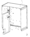
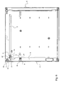
- Figure 1 shows only part of the box (C), to facilitate the explanation of the guide system of the invention.
- This allows, at the opening, the insertion of the door (P) parallel and in the vicinity of the ceiling (1) of the box (C).
- Guiding is effected by means of a slideway (2) comprising two rectilinear sections connected together, one of which is oriented parallel to the ceiling (1), while the other is oriented parallel to the opening of the box, that is, the plane of the door when closed.
- the two sections are in this case perpendicular to each other.
- Each slide (2) is traversed by two lateral pins, one (3) is directly attached to the side edge of the door, while the other (4) is integral with a piece (5) pivotally mounted on the door (P).
- the method of fixing the pin (3) to the door (P) appears more clearly in Figure 2. It is in fact the axial end of a part (6) (see Figure 4), the other end has two branches (7, 7 ').
- the pin (3) is guided by two coaxial orifices made in a tab (8) and the side edge (9) of the door (P).
- the branches (7, 7 ') cooperate with two walls (10, 10'). They comprise, on their external surfaces, notches (15, 15 ') which cooperate with homologous notches (16, 16') protruding from each wall (10, 10 ') to achieve a rack-and-pinion operation allowing a discrete axial adjustment thanks to to the elasticity of the branches (7, 7 ').
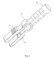
- the same type of pin (4) cooperates with a part (5) (see Figure 5) for pivoting the door (P).
- This pin (4) is always housed in the section of the slide (2) which is parallel to the ceiling (1) of the box (C), and it is guided axially for adjustment in a cylindrical housing (14). of the pivoting part (5).
- This housing (14) in fact separates two parts distinct from the pivoting part: a part comprising the parts (10, 10 ') provided with their notches (16, 16'), and a carriage part (13) guided in the slideway (2) .
- the wall (10) is further extended by a wing (17) provided with orifices (18) can accommodate a shaft (19) (see Figures 1, 2 and 3) materializing the axis around which is performed rotation.
- the housing (14) surrounds the central portion of the pin (4), located near the branches (7,7 ').
- These traditional systems based on mechanical linkages typically constituting a pantograph type configuration, weigh down the mechanical structure and make it much more expensive.
- the axial adjustment of each pin (3,4) ensures its correct positioning at the bottom of the slides to prevent said movement "crab".
- the discrete adjustment of each pin is for example in steps of 0.5 mm, said step being in fact fixed by the notching of the branches (7,7 ') and walls (10,10').
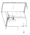
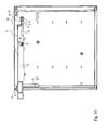
- FIG. 3 clearly shows that in a box configuration (C) as shown, with a peripheral opening frame made of a bevelled folded sheet (11), it is not possible to arrange the slide (2) near the outer edge (12) of said frame. In this case, if it is desired that the outer face of the door (P) is in the same plane as this edge (12), it is necessary to resort to a solution such as that of the invention, with a piece (5). ) to distinguish the axis of the pin (4) and that (19) of the pivoting with pins (3, 4) which are shifted inwardly of the box (C).
- the guide in the portion of the slide (2) oriented substantially parallel to the ceiling (1) of the box (C), is via a pin (4) but also by means of the carriage (13) of the piece (5) which is housed in said portion.
- This guiding mode does not allow the tilting of a portion to the other of the slide (2), the pivot piece (5) still remains housed in the slide portion (2) near the ceiling (1).
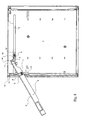
- FIGS. 6a to 6e which illustrate the operation of opening the door
- the axis of the pin (4) and that of the pivot (19) are doubly offset, along a vertical axis and according to a horizontal axis.
- the part (5) undergoes a translation movement during the opening operation and, in the configuration shown, so that the door (P) can be inserted in the vicinity of the ceiling (1) of the box (C ), it is necessary that its pivot axis is shifted upwards, that is to say located close to said ceiling (1).
- FIG 6c shows that in the following phase, when the pivoting of the door (P) is accentuated, the pin (4) and the piece (5) are inserted into the slide (2) towards the bottom of the box. (C), and the pin (3) takes off from the lower end of the slide (2).
- the door (P) When it reaches the upper end of said vertical section, the door (P) is in a horizontal position, that is to say parallel to the ceiling (1) of the box (C).
- the pin (3) is at the left end of the horizontal section of the slide (2), while the pin (4) is almost halfway of this slide (2). ).
Landscapes
- Engineering & Computer Science (AREA)
- Mechanical Engineering (AREA)
- Civil Engineering (AREA)
- Structural Engineering (AREA)
- Hinges (AREA)
- Wing Frames And Configurations (AREA)
- Casings For Electric Apparatus (AREA)
- Specific Sealing Or Ventilating Devices For Doors And Windows (AREA)
- Lighters Containing Fuel (AREA)
Description
- La présente invention concerne un système de guidage d'une porte coulissant entre deux parois latérales d'un volume de rangement de type caisson parallélépipédique, à l'aide d'un système classique à glissières de guidage, la porte s'insérant dans le volume du caisson lorsqu'elle est en position ouverte.
- Des caissons munis de portes obéissant à un tel système d'ouverture sont couramment utilisés dans le domaine du mobilier de bureau. Ces éléments de mobilier sont fermés soit par des volets mobiles coulissants, formés de lattes successives qui procurent une déformabilité à la porte, et permettent son enroulement / déroulement à l'intérieur du volume du caisson, soit par des portes rigides. L'invention concerne lesdites portes rigides, formées en général d'un élément plan indéformable venant obstruer, en position de fermeture, l'ouverture du caisson.
- Dans les,systèmes de guidage connus à ce jour, des éléments du type plot ou galet, en général au nombre de deux dépassant de chacun des chants latéraux de la porte, sont guidés dans une glissière comportant un tronçon d'allure verticale relié à un tronçon d'allure horizontale disposé à proximité et souvent parallèlement au plafond du caisson. Lorsque la porte est fermée, ces chants latéraux sont par conséquent disposés en face des portions d'allure verticale de la glissière, qui sont dès lors masquées.
- Dans cette solution, l'axe de déplacement desdits éléments dépassant est en fait inclus dans le plan moyen de la porte ou à proximité immédiate de celui-ci.
- A titre d'exemple, on connaît le document
US 3 653 158 qui décrit un système de guidage d'une porte coulissant entre deux parois latérales d'un caisson. Les parois latérales sont munies chacune d'une glissière à deux tronçons communicants et d'allure rectiligne. Le déplacement de la porte est obtenu au moyen de pions dépassant latéralement au niveau de ses chants latéraux et disposés symétriquement de part et d'autre de la porte, en coulissant dans les glissières à raison de deux pions par glissière entre une position de fermeture et une position d'ouverture dans laquelle la porte est au moins partiellement logée dans le caisson au voisinage de son plafond. - Cette configuration n'est pas toujours recherchée, car le positionnement relatif particulier de la porte et des glissières qu'elle impose n'est pas toujours réalisable. Il peut ainsi être techniquement nécessaire que la porte soit positionnée en avant de la glissière, c'est-à-dire que cette dernière soit située à l'intérieur du volume du caisson fermé. Ainsi en est-il par exemple lorsque l'encadrement de la porte se réduit à une épaisseur de tôle, et qu'il n'est par conséquent pas possible d'y pratiquer des glissières, mais que la porte doit néanmoins y être encadrée.
- L'objet de l'invention est donc de proposer une configuration dans laquelle est possible de décaler la porte en avant des glissières, par exemple pour répondre à une telle exigence esthétique.
- Le système de guidage de l'invention s'applique plus précisément à une porte coulissant entre deux parois latérales d'un caisson munies chacune d'une glissière à deux tronçons communicants d'allure rectiligne, et permet le déplacement de ladite porte au moyen de pions dépassant latéralement au niveau de ses chants latéraux, disposés symétriquement de part et d'autre de la porte et coulissant dans les glissières à raison de deux pions par glissière.
- Il se caractérise à titre principal en ce que lesdits pions sont décalés vers l'intérieur du volume du caisson, les deux pions supérieurs situés à proximité du plafond lorsque la porte est en position fermée étant solidarisé chacun à une pièce montée en pivotement sur la porte (P) autour d'un axe disposé au voisinage de son chant supérieur.
- Dans cette solution, les pions ne sont alors plus disposés dans le prolongement de la porte, et leurs axes ne sont par conséquent plus contenus ou à proximité immédiate du plan moyen de celle-ci, mais décalés par rapport à ce plan.
- En revanche, l'axe de pivotement reste de préférence dans ou au voisinage immédiat de ce plan moyen. D'un point de vue fonctionnel, cet axe de pivotement doit de plus nécessairement se trouver à proximité du chant supérieur de la porte, afin de permettre le " rangement de celle-ci à proximité du plafond du caisson.
- En fait, l'axe de pivotement de la porte et l'axe des pions supérieurs sont disposés relativement, dans la pièce de pivotement, de telle sorte que lorsque la porte est fermée, lesdits pions supérieurs sont déjà placés dans les portions des glissières d'allure rectiligne orientées sensiblement parallèlement au plafond.
- Cette caractéristique permet de simplifier l'opération d'ouverture, en rendant notamment le mouvement plus fluide par amélioration du guidage initial. Il est d'ailleurs à noter que, dans l'hypothèse d'une configuration dans laquelle les contours de la porte sont disposés, à la fermeture, à proximité du cadre d'ouverture délimité par les bords du caisson, est nécessaire que les pions supérieurs soient toujours situés peu ou prou dans l'axe des portions de glissières d'allure parallèle au plafond. Dans l'hypothèse inverse, si ces pions étaient initialement logés dans les tronçons parallèles à la porte en position fermée, l'opération d'ouverture de la porte nécessiterait un premier déplacement parallèle au plan dudit cadre, et la porte se heurterait alors à son bord supérieur.
- Selon l'invention, lorsque les pions sont tous dans les portions de glissières orientées sensiblement parallèlement au plafond, leurs axes forment de préférence un plan parallèle au plan moyen de la porte ou légèrement incliné par rapport à ce dernier.
- Il y a alors parallélisme entre le plafond du caisson, le positionnement de la porte repliée et le plan contenant l'axe des pions.
- La position de ceux-ci est de préférence au surplus réglable axialement afin de permettre un fonctionnement optimal du coulissement en rapprochant les extrémités libres des pions du fond des glissières, pour éviter tout mouvement "en crabe" lors du déplacement de la porte.
- Ainsi, selon une configuration, les pions forment l'extrémité axiale de pièces de réglage dont l'autre extrémité est constituée de deux branches parallèles dont les surfaces externes sont au contact de parois extérieures, l'une de la surface ou de la paroi étant munie de crans destinés à coopérer avec un relief de l'autre dans un fonctionnement de type crémaillère permettant, par déformation élastique des branches, un réglage axial discret entre plusieurs positions.
- De préférence, ledit relief est en réalité également constitué de crans homologues aux premiers et interagissant avec eux.
- Pour procéder à un déplacement axial, il suffit de pincer, à la manière d'une pince à linge, lesdites branches pour les rapprocher l'une de l'autre, et de pousser / tirer la pièce de réglage d'un ou plusieurs crans.
- Cette pièce est en outre guidée axialement par au moins un orifice cylindrique logeant une portion centrale du pion.
- Dans le cas des pions supérieurs, le guidage est effectué par un logement cylindrique pratiqué en fait dans la pièce de pivotement.
- Dans le cas des autres pions, le guidage est effectué simultanément par un orifice pratiqué dans le chant latéral de la porte et par un orifice coaxial pratiqué dans une patte parallèle audit chant et située vers l'intérieur de la porte.
- L'invention va à présent être décrite en référence aux figures annexées, pour lesquelles :
- la figure 1 est une vue en perspective d'une partie du caisson et de la porte, faisant apparaître l'un des systèmes de guidage latéraux ;
- la figure 2 constitue un agrandissement détaillant la représentation de la figure 1, dans lequel les modes de fixation des pions à la porte sont notamment précisés ;
- la figure 3 est une vue en perspective d'une partie de l'extérieur du caisson, porte fermée, représentant le système de pivotement ;
- la figure 4 représente, toujours en perspective, une pièce de réglage ;
- la figure 5 montre la pièce de pivotement ; et
- les figures 6a à 6e montrent le positionnement relatif successif des différents éléments du système de guidage de l'invention lors d'une opération d'ouverture de la porte.
- La figure 1 ne représente qu'une partie du caisson (C), pour faciliter l'explication du système de guidage de l'invention. Celui-ci permet, à l'ouverture, l'insertion de la porte (P) parallèlement et au voisinage du plafond (1) du caisson (C). Le guidage s'effectue au moyen d'une glissière (2) comportant deux tronçons rectilignes reliés entre eux, dont l'un est orienté parallèlement au plafond (1), alors que l'autre est orienté parallèlement à l'ouverture du caisson, c'est-à-dire au plan de la porte lorsqu'elle est fermée. Les deux tronçons sont en l'occurrence perpendiculaires l'un à l'autre.
- Chaque glissière (2) est donc parcourue par deux pions latéraux, dont l'un (3) est directement fixé au chant latéral de la porte, alors que l'autre (4) est solidaire d'une pièce (5) montée à pivotement sur la porte (P).
- Le mode de fixation du pion (3) à la porte (P) apparaît plus clairement en figure 2. Il constitue en fait l'extrémité axiale d'une pièce (6) (voir figure 4) dont l'autre extrémité comporte deux branches (7, 7'). Le pion (3) est guidé par deux orifices coaxiaux pratiqués dans une patte (8) et le chant latéral (9) de la porte (P). Les branches (7, 7') coopèrent avec deux parois (10, 10'). Elles comportent, sur leurs surfaces externes, des crans (15, 15') qui coopèrent avec des crans homologues (16, 16') dépassant de chaque paroi (10, 10') pour réaliser un fonctionnement en crémaillère permettant un réglage axial discret grâce à l'élasticité des branches (7, 7').
- Le même type de pion (4) coopère avec une pièce (5) (voir en figure 5) permettant le pivotement de la porte (P). Ce pion (4) est toujours logé dans le tronçon de la glissière (2) qui est parallèle au plafond (1) du caisson (C), et il est guidé axialement, en vue de son réglage, dans un logement cylindrique (14) de la pièce de pivotement (5). Ce logement (14) sépare en fait deux parties distinctes de la pièce de pivotement : une partie comportant les parties (10,10') munies de leurs crantages (16,16'), et une partie formant chariot (13) guidé dans la glissière (2).La paroi (10) est en outre prolongée par une aile (17) munie d'orifices (18) pouvant loger un arbre (19) (voir en figures 1,2 et 3) matérialisant l'axe autour duquel s'effectue la rotation. Le logement (14) entoure la partie centrale du pion (4), située à proximité des branches (7,7').
- Le réglage axial des deux pions (3, 4), rendu possible manuellement par simple pincement des branches (7, 7') accompagné d'une poussée ou d'une traction axiale, permet d'éviter l'utilisation d'un système complexe pour empêcher le déplacement dit « en crabe » de la porte dans les glissières. Ces systèmes traditionnels, basés sur des tringleries mécaniques constituant typiquement une configuration de type en pantographe, alourdissent la structure mécanique et la rendent bien plus onéreuse. En l'espèce, le réglage axial de chaque pion (3,4) permet d'assurer son positionnement correct au fond des glissières pour éviter ledit déplacement « en crabe ». Le réglage discret de chaque pion se fait par exemple par pas de 0,5 mm, ledit pas étant en fait fixé par le crantage des branches (7,7') et des parois (10,10').
- La figure 3 montre bien que dans une configuration de caisson (C) telle que montrée, avec un cadre périphérique d'ouverture fait d'une tôle repliée en biseau (11), il n'est pas possible de disposer la glissière (2) à proximité de l'arête extérieure (12) dudit cadre. Dans ce cas, si l'on veut que la façade extérieure de la porte (P) soit dans le même plan que cette arête (12), il faut recourir à une solution telle que celle de l'invention, avec une pièce (5) permettant de distinguer l'axe du pion (4) et celui (19) du pivotement avec des pions (3, 4) qui sont décalés vers l'intérieur du caisson (C). Il est à noter que le guidage, dans la portion de la glissière (2) orientée sensiblement parallèlement au plafond (1) du caisson (C), se fait via un pion (4) mais également au moyen du chariot (13) de la pièce (5) qui est logé dans ladite portion. Ce mode de guidage ne permettant pas le basculement d'une portion à l'autre de la glissière (2), la pièce de pivotement (5) reste bien toujours logée dans la partie de glissière (2) proche du plafond (1).
- En considérant les figures 6a à 6e, qui illustrent l'opération d'ouverture de la porte, il est manifeste que l'axe du pion (4) et celui du pivotement (19) sont doublement décalés, selon un axe vertical et selon un axe horizontal. La pièce (5) ne subit qu'un mouvement de translation lors de l'opération d'ouverture et, dans la configuration montrée, pour que la porte (P) puisse s'insérer au voisinage du plafond (1) du caisson (C), il est nécessaire que son axe de pivotement soit décalé vers le haut, c'est-à-dire situé à proximité dudit plafond (1). Cela répond à une double nécessité esthétique et fonctionnelle, cette dernière se situant dans la réalisation d'une ouverture de surface maximale.
- En position de fermeture de la porte (P), représentée en figure 6 a, le pion (3) est en butée intérieure dans le tronçon vertical de la glissière (2), alors que le pion (4) et le chariot (13) sont déjà engagés dans son tronçon horizontal. Cela facilite le guidage à l'ouverture, et constitue l'une des justifications du décalage, selon un axe horizontal, des axes respectivement de pivotement de la porte et de déplacement du pion (4). Lorsqu'on démarre l'opération d'ouverture de la porte (P), la possibilité de pivotement (19) de la porte (P) permet un premier déplacement du pion (4) de la pièce (5) vers le fond du caisson (C), sans qu'il se produise de déplacement du pion (3), qui reste sensiblement en butée au bas du tronçon vertical de la glissière (2) : c'est ce qui apparaît en figure 6 b. La figure suivante 6 c montre que dans la phase suivante, lorsqu'on accentue le pivotement de la porte (P), le pion (4) et la pièce (5) s'enfoncent dans la glissière (2) vers le fond du caisson (C), et le pion (3) décolle de l'extrémité inférieure de la glissière (2). Lorsqu'il atteint l'extrémité supérieure dudit tronçon vertical, la porte (P) se retrouve en position horizontale, c'est-à-dire parallèle au plafond (1) du caisson (C). Dans ce cas, montré en figure 6 d, le pion (3) se trouve à l'extrémité gauche du tronçon horizontal de la glissière (2), alors que le pion (4) est presque à mi-parcours de cette glissière (2).
- Enfin, en figure 6 e, le pion (4) et la pièce (5) sont repoussés à l'extrémité droite du tronçon horizontal, et la porte (P) est logée, pratiquement en totalité, à l'intérieur du caisson (C).
Claims (10)
- Système de guidage d'une porte (P) coulissant entre deux parois latérales d'un caisson (C), lesquelles sont munies chacune d'une glissière (2) à deux tronçons communicants d'allure rectiligne, le déplacement de ladite porte (P) étant obtenu au moyen de pions (3, 4) dépassant latéralement au niveau de ses chants latéraux, disposés symétriquement de part et d'autre de la porte (P) et coulissant dans lesdites glissières (2) à raison de deux pions (3, 4) par glissière (2) entre une position de fermeture et une position d'ouverture dans laquelle la porte (P) est au moins partiellement logée dans le caisson (C) au voisinage de son plafond (1), caractérisé en ce que les axes des pions (3, 4) sont décalés vers l'intérieur du volume du caisson (C), les deux pions supérieurs (4) situés à proximité du plafond (1) lorsque la porte (P) est en position fermée étant solidarisé chacun à une pièce montée en pivotement sur la porte (P) autour d'un axe (19) disposé au voisinage de son chant supérieur.
- Système de guidage selon la revendication précédente, caractérisé en ce que l'axe de pivotement (19) de la porte (P) est dans le plan moyen de ladite porte (P).
- Système de guidage selon l'une quelconque des revendications précédentes, caractérisé en ce que l'axe de pivotement (19) de la porte (P) et l'axe des pions supérieurs (4) sont disposés relativement l'un à l'autre, dans la pièce de pivotement (5), de telle sorte que lorsque la porte (P) est fermée, lesdits pions supérieurs (4) sont placés dans les portions des glissières (2) d'allure rectiligne orientées sensiblement parallèlement au plafond (1).
- Système de guidage selon l'une quelconque des revendications précédentes, caractérisé en ce que, lorsque les pions (3, 4) sont tous dans les portions de glissières (2) orientées sensiblement parallèlement au plafond (1), leurs axes forment un plan parallèle au plan moyen de la porte (P) ou légèrement incliné par rapport à ce dernier.
- Système de guidage selon l'une quelconque des revendications précédentes, caractérisé en ce que la position des pions (3, 4) est réglable axialement.
- Système de guidage selon la revendication précédente, caractérisé en ce que les pions (3, 4) forment l'extrémité axiale de pièces de réglage dont l'autre extrémité est constituée de deux branches (7, 7') parallèles dont les surfaces externes sont au contact de parois extérieures (10, 10'), l'une de la surface ou de la paroi étant munie de crans (15, 15') destinés à coopérer avec un relief de l'autre dans un fonctionnement de type crémaillère, permettant par déformation élastique des branches (7, 7') un réglage axial discret de la pièce entre plusieurs positions.
- Système de guidage selon la revendication précédente, caractérisé en ce que ledit relief est également constitué de crans (16, 16') homologues aux premiers (15, 15').
- Système de guidage selon l'une des revendications 6 et 7, caractérisé en ce que la pièce de réglage est guidée axialement par au moins un orifice cylindrique logeant une portion centrale du pion.
- Système de guidage selon la revendication précédente, caractérisé en ce que, dans le cas des pions supérieurs (4), le guidage est effectué par un logement cylindrique (14) pratiqué dans la pièce de pivotement (5).
- Système de guidage selon la revendication 8, caractérisé en ce que dans le cas d'autres pions (3), le guidage est effectué simultanément par un orifice pratiqué dans le chant latéral (9) de la porte (P), et par un orifice coaxial pratiqué dans une patte (8) parallèle audit chant (9) située vers l'intérieur de la porte (P).
Priority Applications (4)
| Application Number | Priority Date | Filing Date | Title |
|---|---|---|---|
| DE60318587T DE60318587D1 (de) | 2003-10-29 | 2003-10-29 | Tür mit versetzter Drehachse |
| AT03360125T ATE383489T1 (de) | 2003-10-29 | 2003-10-29 | Tür mit versetzter drehachse |
| EP03360125A EP1528212B1 (fr) | 2003-10-29 | 2003-10-29 | Porte à axe de pivotement décalé |
| PCT/FR2004/002768 WO2005042900A1 (fr) | 2003-10-29 | 2004-10-27 | Porte a axe de pivotement decale |
Applications Claiming Priority (1)
| Application Number | Priority Date | Filing Date | Title |
|---|---|---|---|
| EP03360125A EP1528212B1 (fr) | 2003-10-29 | 2003-10-29 | Porte à axe de pivotement décalé |
Publications (2)
| Publication Number | Publication Date |
|---|---|
| EP1528212A1 EP1528212A1 (fr) | 2005-05-04 |
| EP1528212B1 true EP1528212B1 (fr) | 2008-01-09 |
Family
ID=34400608
Family Applications (1)
| Application Number | Title | Priority Date | Filing Date |
|---|---|---|---|
| EP03360125A Expired - Lifetime EP1528212B1 (fr) | 2003-10-29 | 2003-10-29 | Porte à axe de pivotement décalé |
Country Status (4)
| Country | Link |
|---|---|
| EP (1) | EP1528212B1 (fr) |
| AT (1) | ATE383489T1 (fr) |
| DE (1) | DE60318587D1 (fr) |
| WO (1) | WO2005042900A1 (fr) |
Cited By (1)
| Publication number | Priority date | Publication date | Assignee | Title |
|---|---|---|---|---|
| WO2021161056A1 (fr) | 2020-02-14 | 2021-08-19 | Steelcase Inc. | Meuble, en particulier armoire |
Families Citing this family (2)
| Publication number | Priority date | Publication date | Assignee | Title |
|---|---|---|---|---|
| DE202008006754U1 (de) * | 2008-05-19 | 2009-10-01 | Hettich-Heinze Gmbh & Co. Kg | Justiereinrichtung für eine in einen Möbelkorpus einschieb- und ausziehbare Frontklappe |
| IT1403670B1 (it) * | 2011-02-02 | 2013-10-31 | Bruno Fattorini & Partners Srl | Dispositivo di incernieramento, particolarmente per ante di contenitori e simili. |
Family Cites Families (6)
| Publication number | Priority date | Publication date | Assignee | Title |
|---|---|---|---|---|
| US1678453A (en) * | 1925-09-08 | 1928-07-24 | Welch Mfg Company | Door structure for display cabinets |
| FR760931A (fr) * | 1933-09-18 | 1934-03-06 | Sanitas Ets | Volet roulant notamment pour tables, guéridons, vitrines, placards, etc. |
| DE1216732B (de) * | 1955-03-18 | 1966-05-12 | Robert Krause K G Zweigniederl | Beschlag fuer eine Drehschiebetuer |
| FR1202659A (fr) * | 1958-09-20 | 1960-01-12 | Porte rigide escamotable, pour meubles ou autres applications | |
| US3653158A (en) * | 1970-06-22 | 1972-04-04 | Westinghouse Electric Corp | Arrangement for supporting a closure member from a track |
| US5083847A (en) * | 1991-01-28 | 1992-01-28 | Transfer Flow International, Inc. | Pocket door attachment fitting for a cabinet |
-
2003
- 2003-10-29 DE DE60318587T patent/DE60318587D1/de not_active Expired - Lifetime
- 2003-10-29 EP EP03360125A patent/EP1528212B1/fr not_active Expired - Lifetime
- 2003-10-29 AT AT03360125T patent/ATE383489T1/de not_active IP Right Cessation
-
2004
- 2004-10-27 WO PCT/FR2004/002768 patent/WO2005042900A1/fr not_active Ceased
Cited By (1)
| Publication number | Priority date | Publication date | Assignee | Title |
|---|---|---|---|---|
| WO2021161056A1 (fr) | 2020-02-14 | 2021-08-19 | Steelcase Inc. | Meuble, en particulier armoire |
Also Published As
| Publication number | Publication date |
|---|---|
| EP1528212A1 (fr) | 2005-05-04 |
| DE60318587D1 (de) | 2008-02-21 |
| WO2005042900A1 (fr) | 2005-05-12 |
| ATE383489T1 (de) | 2008-01-15 |
Similar Documents
| Publication | Publication Date | Title |
|---|---|---|
| EP0290304B1 (fr) | Profile pour la réalisation d'une structure de panneau de baignoire, et structure réalisée avec le profile | |
| EP0911469B1 (fr) | Porte pivotante du type comportant au moins un battant sur lequel sont montées parallèles deux tringles par l'intermédiaire de biellettes | |
| FR2706120A3 (fr) | Charnière pour appareils électroménagers encastrables, en particulier pour réfrigérateurs . | |
| FR2705722A1 (fr) | Dispositif de manÓoeuvre de serrures par poussée ou traction. | |
| FR2858008A3 (fr) | Moyen de transport et dispositif de tamissage de lumiere a utiliser avec ce moyen de support, et fenetre comportant ce moyen de support | |
| EP1528212B1 (fr) | Porte à axe de pivotement décalé | |
| EP2832949B1 (fr) | Système de commande de lames de jalousie et jalousie correspondante | |
| EP2840220B1 (fr) | Système de commande pour lames de jalousies | |
| FR2588605A1 (fr) | Systeme manoeuvrable d'arret d'un battant de volet et ensemble de crochetage dudit battant. | |
| EP1524399A1 (fr) | Portillon de sécurité | |
| EP2386706B1 (fr) | Dispositif de verrouillage pour un vantail semi-fixe | |
| FR2667647A1 (fr) | Systeme manóoeuvrable d'arret d'un battant de volet et ensemble de crochetage dudit battant. | |
| EP1396603B1 (fr) | Vantail pour porte sectionnelle et porte comprenant un tel vantail | |
| EP0697494B1 (fr) | Rails de guidage pour rideaux coulissants | |
| EP1913842A1 (fr) | Dispositif de guidage pour tiroirs de meubles | |
| FR2526530A1 (fr) | Refrigerateur | |
| FR2765911A1 (fr) | Dispositif de blocage pour volet roulant | |
| FR2629856A1 (fr) | ||
| CH684151A5 (fr) | Fermoir de bracelet. | |
| EP2061944B1 (fr) | Ensemble a charniere a fixation coplanaire | |
| FR2825406A1 (fr) | Dispositif de montage a articulation d'un ouvrant sur un dormant et armoire electrique a deux sens d'ouverture comportant un tel dispositif | |
| FR2806437A1 (fr) | Logement de pivot de basculement pour dispositif oscillobattants | |
| FR2487899A1 (fr) | Coulisse perfectionnee de porte battante | |
| EP4541222A1 (fr) | Fermoir à boucle déployante pour bracelet notamment d'une montre | |
| EP0643191A1 (fr) | Ouvrant coulissant |
Legal Events
| Date | Code | Title | Description |
|---|---|---|---|
| PUAI | Public reference made under article 153(3) epc to a published international application that has entered the european phase |
Free format text: ORIGINAL CODE: 0009012 |
|
| AK | Designated contracting states |
Kind code of ref document: A1 Designated state(s): AT BE BG CH CY CZ DE DK EE ES FI FR GB GR HU IE IT LI LU MC NL PT RO SE SI SK TR |
|
| AX | Request for extension of the european patent |
Extension state: AL LT LV MK |
|
| 17P | Request for examination filed |
Effective date: 20050506 |
|
| AKX | Designation fees paid |
Designated state(s): AT BE BG CH CY CZ DE DK EE ES FI FR GB GR HU IE IT LI LU MC NL PT RO SE SI SK TR |
|
| GRAP | Despatch of communication of intention to grant a patent |
Free format text: ORIGINAL CODE: EPIDOSNIGR1 |
|
| GRAS | Grant fee paid |
Free format text: ORIGINAL CODE: EPIDOSNIGR3 |
|
| GRAA | (expected) grant |
Free format text: ORIGINAL CODE: 0009210 |
|
| AK | Designated contracting states |
Kind code of ref document: B1 Designated state(s): AT BE BG CH CY CZ DE DK EE ES FI FR GB GR HU IE IT LI LU MC NL PT RO SE SI SK TR |
|
| REG | Reference to a national code |
Ref country code: GB Ref legal event code: FG4D Free format text: NOT ENGLISH |
|
| REG | Reference to a national code |
Ref country code: CH Ref legal event code: EP |
|
| REG | Reference to a national code |
Ref country code: IE Ref legal event code: FG4D Free format text: LANGUAGE OF EP DOCUMENT: FRENCH |
|
| REF | Corresponds to: |
Ref document number: 60318587 Country of ref document: DE Date of ref document: 20080221 Kind code of ref document: P |
|
| PG25 | Lapsed in a contracting state [announced via postgrant information from national office to epo] |
Ref country code: SI Free format text: LAPSE BECAUSE OF FAILURE TO SUBMIT A TRANSLATION OF THE DESCRIPTION OR TO PAY THE FEE WITHIN THE PRESCRIBED TIME-LIMIT Effective date: 20080109 Ref country code: NL Free format text: LAPSE BECAUSE OF FAILURE TO SUBMIT A TRANSLATION OF THE DESCRIPTION OR TO PAY THE FEE WITHIN THE PRESCRIBED TIME-LIMIT Effective date: 20080109 |
|
| NLV1 | Nl: lapsed or annulled due to failure to fulfill the requirements of art. 29p and 29m of the patents act | ||
| PG25 | Lapsed in a contracting state [announced via postgrant information from national office to epo] |
Ref country code: FI Free format text: LAPSE BECAUSE OF FAILURE TO SUBMIT A TRANSLATION OF THE DESCRIPTION OR TO PAY THE FEE WITHIN THE PRESCRIBED TIME-LIMIT Effective date: 20080109 Ref country code: ES Free format text: LAPSE BECAUSE OF FAILURE TO SUBMIT A TRANSLATION OF THE DESCRIPTION OR TO PAY THE FEE WITHIN THE PRESCRIBED TIME-LIMIT Effective date: 20080420 |
|
| GBV | Gb: ep patent (uk) treated as always having been void in accordance with gb section 77(7)/1977 [no translation filed] | ||
| PG25 | Lapsed in a contracting state [announced via postgrant information from national office to epo] |
Ref country code: AT Free format text: LAPSE BECAUSE OF FAILURE TO SUBMIT A TRANSLATION OF THE DESCRIPTION OR TO PAY THE FEE WITHIN THE PRESCRIBED TIME-LIMIT Effective date: 20080109 Ref country code: BG Free format text: LAPSE BECAUSE OF FAILURE TO SUBMIT A TRANSLATION OF THE DESCRIPTION OR TO PAY THE FEE WITHIN THE PRESCRIBED TIME-LIMIT Effective date: 20080409 |
|
| PG25 | Lapsed in a contracting state [announced via postgrant information from national office to epo] |
Ref country code: PT Free format text: LAPSE BECAUSE OF FAILURE TO SUBMIT A TRANSLATION OF THE DESCRIPTION OR TO PAY THE FEE WITHIN THE PRESCRIBED TIME-LIMIT Effective date: 20080609 |
|
| REG | Reference to a national code |
Ref country code: IE Ref legal event code: FD4D |
|
| PG25 | Lapsed in a contracting state [announced via postgrant information from national office to epo] |
Ref country code: SE Free format text: LAPSE BECAUSE OF FAILURE TO SUBMIT A TRANSLATION OF THE DESCRIPTION OR TO PAY THE FEE WITHIN THE PRESCRIBED TIME-LIMIT Effective date: 20080409 Ref country code: SK Free format text: LAPSE BECAUSE OF FAILURE TO SUBMIT A TRANSLATION OF THE DESCRIPTION OR TO PAY THE FEE WITHIN THE PRESCRIBED TIME-LIMIT Effective date: 20080109 Ref country code: CZ Free format text: LAPSE BECAUSE OF FAILURE TO SUBMIT A TRANSLATION OF THE DESCRIPTION OR TO PAY THE FEE WITHIN THE PRESCRIBED TIME-LIMIT Effective date: 20080109 Ref country code: IE Free format text: LAPSE BECAUSE OF FAILURE TO SUBMIT A TRANSLATION OF THE DESCRIPTION OR TO PAY THE FEE WITHIN THE PRESCRIBED TIME-LIMIT Effective date: 20080109 Ref country code: DK Free format text: LAPSE BECAUSE OF FAILURE TO SUBMIT A TRANSLATION OF THE DESCRIPTION OR TO PAY THE FEE WITHIN THE PRESCRIBED TIME-LIMIT Effective date: 20080109 |
|
| PLBE | No opposition filed within time limit |
Free format text: ORIGINAL CODE: 0009261 |
|
| STAA | Information on the status of an ep patent application or granted ep patent |
Free format text: STATUS: NO OPPOSITION FILED WITHIN TIME LIMIT |
|
| PG25 | Lapsed in a contracting state [announced via postgrant information from national office to epo] |
Ref country code: RO Free format text: LAPSE BECAUSE OF FAILURE TO SUBMIT A TRANSLATION OF THE DESCRIPTION OR TO PAY THE FEE WITHIN THE PRESCRIBED TIME-LIMIT Effective date: 20080109 |
|
| 26N | No opposition filed |
Effective date: 20081010 |
|
| PG25 | Lapsed in a contracting state [announced via postgrant information from national office to epo] |
Ref country code: GB Free format text: LAPSE BECAUSE OF FAILURE TO SUBMIT A TRANSLATION OF THE DESCRIPTION OR TO PAY THE FEE WITHIN THE PRESCRIBED TIME-LIMIT Effective date: 20080109 |
|
| PG25 | Lapsed in a contracting state [announced via postgrant information from national office to epo] |
Ref country code: DE Free format text: LAPSE BECAUSE OF FAILURE TO SUBMIT A TRANSLATION OF THE DESCRIPTION OR TO PAY THE FEE WITHIN THE PRESCRIBED TIME-LIMIT Effective date: 20080410 |
|
| BERE | Be: lapsed |
Owner name: STEELCASE S.A. Effective date: 20081031 |
|
| PG25 | Lapsed in a contracting state [announced via postgrant information from national office to epo] |
Ref country code: EE Free format text: LAPSE BECAUSE OF FAILURE TO SUBMIT A TRANSLATION OF THE DESCRIPTION OR TO PAY THE FEE WITHIN THE PRESCRIBED TIME-LIMIT Effective date: 20080109 |
|
| PG25 | Lapsed in a contracting state [announced via postgrant information from national office to epo] |
Ref country code: MC Free format text: LAPSE BECAUSE OF NON-PAYMENT OF DUE FEES Effective date: 20081031 |
|
| REG | Reference to a national code |
Ref country code: CH Ref legal event code: PL |
|
| REG | Reference to a national code |
Ref country code: FR Ref legal event code: ST Effective date: 20090630 |
|
| PG25 | Lapsed in a contracting state [announced via postgrant information from national office to epo] |
Ref country code: CY Free format text: LAPSE BECAUSE OF FAILURE TO SUBMIT A TRANSLATION OF THE DESCRIPTION OR TO PAY THE FEE WITHIN THE PRESCRIBED TIME-LIMIT Effective date: 20080109 |
|
| PG25 | Lapsed in a contracting state [announced via postgrant information from national office to epo] |
Ref country code: IT Free format text: LAPSE BECAUSE OF FAILURE TO SUBMIT A TRANSLATION OF THE DESCRIPTION OR TO PAY THE FEE WITHIN THE PRESCRIBED TIME-LIMIT Effective date: 20080109 |
|
| PG25 | Lapsed in a contracting state [announced via postgrant information from national office to epo] |
Ref country code: BE Free format text: LAPSE BECAUSE OF NON-PAYMENT OF DUE FEES Effective date: 20081031 |
|
| PG25 | Lapsed in a contracting state [announced via postgrant information from national office to epo] |
Ref country code: CH Free format text: LAPSE BECAUSE OF NON-PAYMENT OF DUE FEES Effective date: 20081031 Ref country code: LI Free format text: LAPSE BECAUSE OF NON-PAYMENT OF DUE FEES Effective date: 20081031 Ref country code: FR Free format text: LAPSE BECAUSE OF NON-PAYMENT OF DUE FEES Effective date: 20081031 |
|
| PG25 | Lapsed in a contracting state [announced via postgrant information from national office to epo] |
Ref country code: HU Free format text: LAPSE BECAUSE OF FAILURE TO SUBMIT A TRANSLATION OF THE DESCRIPTION OR TO PAY THE FEE WITHIN THE PRESCRIBED TIME-LIMIT Effective date: 20080710 Ref country code: LU Free format text: LAPSE BECAUSE OF NON-PAYMENT OF DUE FEES Effective date: 20081029 |
|
| PG25 | Lapsed in a contracting state [announced via postgrant information from national office to epo] |
Ref country code: TR Free format text: LAPSE BECAUSE OF FAILURE TO SUBMIT A TRANSLATION OF THE DESCRIPTION OR TO PAY THE FEE WITHIN THE PRESCRIBED TIME-LIMIT Effective date: 20080109 |
|
| PG25 | Lapsed in a contracting state [announced via postgrant information from national office to epo] |
Ref country code: GR Free format text: LAPSE BECAUSE OF FAILURE TO SUBMIT A TRANSLATION OF THE DESCRIPTION OR TO PAY THE FEE WITHIN THE PRESCRIBED TIME-LIMIT Effective date: 20080410 |