EP1528007B1 - Blanc for forming a carton bottle carrier - Google Patents
Blanc for forming a carton bottle carrier Download PDFInfo
- Publication number
- EP1528007B1 EP1528007B1 EP04025488A EP04025488A EP1528007B1 EP 1528007 B1 EP1528007 B1 EP 1528007B1 EP 04025488 A EP04025488 A EP 04025488A EP 04025488 A EP04025488 A EP 04025488A EP 1528007 B1 EP1528007 B1 EP 1528007B1
- Authority
- EP
- European Patent Office
- Prior art keywords
- blank according
- handle
- sections
- longitudinal axis
- parts
- Prior art date
- Legal status (The legal status is an assumption and is not a legal conclusion. Google has not performed a legal analysis and makes no representation as to the accuracy of the status listed.)
- Expired - Lifetime
Links
- 210000003739 neck Anatomy 0.000 claims abstract description 10
- 230000002093 peripheral effect Effects 0.000 claims description 10
- 238000004080 punching Methods 0.000 claims description 7
- 238000004026 adhesive bonding Methods 0.000 claims description 6
- 230000002787 reinforcement Effects 0.000 claims description 6
- 239000002655 kraft paper Substances 0.000 claims description 4
- 238000000034 method Methods 0.000 abstract description 13
- 238000003825 pressing Methods 0.000 abstract description 4
- 239000000969 carrier Substances 0.000 description 12
- 239000000853 adhesive Substances 0.000 description 11
- 230000001070 adhesive effect Effects 0.000 description 10
- 230000015572 biosynthetic process Effects 0.000 description 10
- 230000008901 benefit Effects 0.000 description 7
- 230000008569 process Effects 0.000 description 7
- 230000003014 reinforcing effect Effects 0.000 description 7
- 210000002105 tongue Anatomy 0.000 description 7
- 238000004519 manufacturing process Methods 0.000 description 6
- 235000013361 beverage Nutrition 0.000 description 5
- 239000003292 glue Substances 0.000 description 5
- 238000005520 cutting process Methods 0.000 description 4
- 240000006240 Linum usitatissimum Species 0.000 description 3
- 238000005452 bending Methods 0.000 description 3
- 239000011521 glass Substances 0.000 description 3
- 238000004049 embossing Methods 0.000 description 2
- 238000003780 insertion Methods 0.000 description 2
- 230000037431 insertion Effects 0.000 description 2
- 239000000463 material Substances 0.000 description 2
- 238000002360 preparation method Methods 0.000 description 2
- 150000001875 compounds Chemical class 0.000 description 1
- 238000010276 construction Methods 0.000 description 1
- 239000007799 cork Substances 0.000 description 1
- 230000001419 dependent effect Effects 0.000 description 1
- 230000002349 favourable effect Effects 0.000 description 1
- 230000009191 jumping Effects 0.000 description 1
- 239000007788 liquid Substances 0.000 description 1
- 238000012986 modification Methods 0.000 description 1
- 230000004048 modification Effects 0.000 description 1
- 230000000284 resting effect Effects 0.000 description 1
- 238000000926 separation method Methods 0.000 description 1
- 239000007787 solid Substances 0.000 description 1
- 238000003892 spreading Methods 0.000 description 1
- 230000007480 spreading Effects 0.000 description 1
- 230000007704 transition Effects 0.000 description 1
Images


Classifications
-
- B—PERFORMING OPERATIONS; TRANSPORTING
- B65—CONVEYING; PACKING; STORING; HANDLING THIN OR FILAMENTARY MATERIAL
- B65D—CONTAINERS FOR STORAGE OR TRANSPORT OF ARTICLES OR MATERIALS, e.g. BAGS, BARRELS, BOTTLES, BOXES, CANS, CARTONS, CRATES, DRUMS, JARS, TANKS, HOPPERS, FORWARDING CONTAINERS; ACCESSORIES, CLOSURES, OR FITTINGS THEREFOR; PACKAGING ELEMENTS; PACKAGES
- B65D71/00—Bundles of articles held together by packaging elements for convenience of storage or transport, e.g. portable segregating carrier for plural receptacles such as beer cans or pop bottles; Bales of material
- B65D71/40—Bundles of articles held together by packaging elements for convenience of storage or transport, e.g. portable segregating carrier for plural receptacles such as beer cans or pop bottles; Bales of material comprising a plurality of articles held together only partially by packaging elements formed by folding a blank or several blanks
- B65D71/46—Bundles of articles held together by packaging elements for convenience of storage or transport, e.g. portable segregating carrier for plural receptacles such as beer cans or pop bottles; Bales of material comprising a plurality of articles held together only partially by packaging elements formed by folding a blank or several blanks formed by folding a single blank into a tubular element
- B65D71/48—Bundles of articles held together by packaging elements for convenience of storage or transport, e.g. portable segregating carrier for plural receptacles such as beer cans or pop bottles; Bales of material comprising a plurality of articles held together only partially by packaging elements formed by folding a blank or several blanks formed by folding a single blank into a tubular element characterised by the handle
Definitions
- the invention relates to a blank of the type specified in the preamble of claim 1.
- Blanks of this type for the production of single or multi-row carriers for bottles, in particular beverage bottles, are known in various variants ( DE 1 900 965 U1 . FR 2 346 237 A1 . DE 40 34 069 A1 ).
- these blanks form completely prefabricated bottle carriers, which are placed in the erected, ready-to-use state with receiving openings formed in the bottom and top parts on the necks of the bottles to be transported.
- the required for the desired function solid compound of the carrier with the bottles is achieved essentially by positive engagement by surrounding the receiving openings edges are formed such that they snap when placing the carrier on the bottles resiliently under the closure elements.
- each ceiling part can only be made from one layer of the blank, which further impairs the function of the undergrip segments. The latter would also apply if it were attempted to apply such blank forms in an analogous manner to double-row carriers.
- the technical problem underlying the invention is to provide a two- or multi-row blank of the type described above in the manner with centrally arranged carrying handles that results in a stable, simple construction, the weight of 2 x 2, 2 x 3 or can withstand more filled bottles.
- the invention provides the advantage that the grip handle forming portions of the blank forming the handle are integrated into the ceiling or floor part, that both all intended to accommodate the bottle necks openings have closed contours and in the finished carrier two superimposed ceiling parts available.
- This makes it possible, in particular, to provide such blanks or bottle carriers produced therefrom with carrying handles that can be grasped over the upper cover part and can be detected with the whole hand, which have hitherto proved to be particularly stable with regard to the formation of the undercut segments (eg. DE 40 34 069 A1 ).
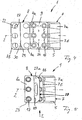
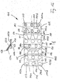
- Fig. 1 shows a first embodiment of a blank 1 according to the invention in a flat, unfolded state, ie substantially as it comes from a corresponding punching device.
- a kraft cardboard is used with a weight that depends on the number and size of the bottles to be packaged z. B. 300 g / m 2 to 450 g / m 2 may be.
- the blank 1 includes a base member having a substantially rectangular outer contour and two long, parallel to a longitudinal axis 2 extending side edges 3a, 3b and two preferably arranged perpendicular thereto, short side edges 4a and 4b.
- the basic element is subdivided into a plurality of fields and in particular contains a bottom part 5, an in Fig. 1 to the left, first side part 6 and one in Fig. 1
- the base member includes a left of the first side part 6 lying, first ceiling part 8 and a right of the second side part 7 lying, second ceiling part 9. All these parts 5 to 9 have substantially rectangular peripheral contours and are arranged in the direction of the longitudinal axis 2 of the blank 1 side by side so that their long sides are substantially perpendicular and their short sides are arranged substantially parallel to the longitudinal axis 2.
- the parts 5 to 9 are separated by preferably substantially perpendicular to the longitudinal axis 2 extending, imaginary folding lines, which in order to facilitate further explained under folding the various parts but also depending on the usefulness of already applied during punching embossing, grooves, combined creasing / cutting Lines od. Like. May exist.
- a first fold line 10 and a second fold line 11 between the first side part 6 and the first ceiling part 8, a third fold line 12 and between the second side part 7 and the second ceiling part 9, a fourth fold line 14 is provided.
- the two side parts 6 and 7 in each two parallel to the longitudinal axis 2 adjacent side part sections 6a, 6b and 7a, 7b be divided, preferably separated by perpendicular to the longitudinal axis 2 extending fifth and sixth, also in the punching process attached fold lines 15 and 16 are.
- the side part sections 6a, 7a adjoining the bottom part 5 have a comparatively large height h1
- the side part sections 6b, 7b adjoining the ceiling parts 8, 9 have a comparatively small height h2.
- the second ceiling part 9 has in two preferably perpendicular to the longitudinal axis 2 rows a plurality, in the embodiment three each according to the associated bottle shape and size spaced first openings 17, the peripheral lines or edges 18 of concentric, preferably formed as a seventh fold lines, closed perimeter 19 are surrounded. Between the two circumferential lines 18 and 19, ie in the peripheral areas surrounding the openings 17, the blank 1 each have a plurality of circumferentially adjacent sectors 20, which are separated by radially extending, preferably during the punching separation lines 21 and therefore only along the circumferential lines 19 are connected to the blank 1.
- the sectors 20 form so-called under-grip segments, which are used to reach under the closure elements od. Like. Of bottles, as further below with reference to Fig. 11 to 14 is explained.
- the first cover part 8 has in two preferably perpendicular to the longitudinal axis 2 extending rows on the number of first openings 17 corresponding number of second openings 22. These are arranged at the same distances as the first openings 17 and provided with peripheral lines or edges 23 which preferably have the same diameter as the peripheral lines 19 surrounding the first openings 17.
- the peripheral lines 18, 19, 23 circular, wherein the circumferential lines 18 of the first openings 17 according to the intended number of eight sub-grip segments 20 can also form an octagon.
- the bottom part 5 has third openings 24, which are provided in the same number as the first and second openings 17, 22 and in a corresponding arrangement like these.
- the openings 24 have circular peripheral lines 25 and diameter, which are expedient slightly larger than that of the openings 22.
- the bottom part 5 and the second ceiling part 9 parallel to the longitudinal axis 2 substantially equal widths, so that they can be arranged one above the other in a conventional manner for producing a bottle carrier, that the openings 17, 22 and 24 are aligned.
- Blanks of the type described are basically known (eg DE 40 34 069 A1 ) and therefore need not be explained to the person skilled in the art.
- the first cover part 8 has two ceiling part sections 8a and 8b spaced in the direction of the longitudinal axis 2, a first ceiling part section 8a at the fold line 12 and a second cover part section 8b at the side window 4b ends.
- a handle member 27 is also arranged according to the invention, the two contiguous, in the direction of the longitudinal axis 2 adjacent handle portions 27a and 27b, the mutually facing side edges along a substantially perpendicular to the longitudinal axis 2 extending, eighth fold line 28 with each other are connected.
- the one handle portion 27a at its other side edge along a ninth fold line 29 with the inner ceiling portion 8a and second handle portion 27b at its other side edge along a tenth fold line 30 with the outer ceiling portion 8b is connected, wherein the two fold lines 29 and 30 also arranged substantially perpendicular to the longitudinal axis 2 and preferably formed as the other fold lines.
- the fold line 34 preferably coincides substantially with the side edge 3b of the base element of the blank 32 and therefore lies substantially parallel to the longitudinal axis 2.
- the cover 33 advantageously has a measured perpendicular to the longitudinal axis 2 height h3, which is preferably at most equal to the sum of the Heights h1 and h2 and expediently substantially equal to the height h1 of the side part sections 6a and 7a, but how it is smaller than the depth of the bottom part 9 measured in the same direction.
- the fold line 34 is preferably provided with a perforation, so that the cover 33 can be easily torn off the bottom part 5.
- the blank 32 has two similar lateral cover members 33 which are connected on opposite sides of the longitudinal axis 2 with the bottom part 5 and preferably mirror-symmetrical to the longitudinal axis 2, so that the description for a cover 33 in the same Way also for the other cover 33 applies.
- a first stage of the process At least one of the two handle portions 27 a and 27 b z.
- the two handle portions 27a, 27b by about 90 ° to the ninth fold line 29 and the tenth fold line 30 in Fig. 1 and 2 folded back.
- the fold lines 29, 30 are simultaneously moved towards each other to the mutual contact to the Handle sections 27a, 27b also about 180 ° around the connecting them eighth fold line 28 to fold from until they lie with their inner sides together and are firmly connected to each other by means of the adhesive in the zone 35.
- the ceiling part 8 is shown a front view in the direction of an arrow a for the state obtained after folding.
- a further process step ( Fig. 4 ) will be in Fig. 1 and 2 180 ° about the second fold line 11, whereby the inside of the side part 7 and an adjacent portion of the cover part 8 on the cover parts 33 and the remaining portion of the ceiling part 9 on the inside the first side part 6 comes to rest.
- the dimensions of the various parts z. B. chosen so that after this stage of the process, the side edge 4 a of the ceiling part 9 comes to rest approximately above the third fold line 12.
- the cover members 33 are the parts 7, 9 in an analogous manner directly on the réelleseites of the bottom part 5.
- the ceiling part 9 is on its now upper side in the range of glue zones 36, which in Fig. 4 indicated by crosses, covered with an adhesive.
- a firm connection between the two cover parts 8, 9 is made by applying pressure to the ceiling part 8 and curing the glue by gluing.
- Fig. 5 shows, the arrangement made such that the edge lines 23 of the openings 22 coaxially over the Edge lines 19 of the openings 17 come to rest.
- the width of the ceiling part 9 measured in the direction of the longitudinal axis 2 substantially corresponds to the sum of the widths of the ceiling part sections 8a and 8b.
- the grip part 27 is now arranged above the first ceiling part 8.
- the handle portion 27 is around the fold lines 29 and 30, of which in Fig. 5 only the fold line 29 is visible, relative to the ceiling part 8 pivotally, since the two fold lines 29, 30 in the off Fig. 3 apparent state are close together and form a common pivot axis.
- the arrangement is preferably made so that the two handle portions 27a, 27b are biased in a preferred pivoting direction and are not perpendicular to the top of the ceiling portion 8 in the unused state, but automatically form an angle with this, which is preferably substantially smaller than 90 ° , as Fig. 5 and 6 demonstrate. This is z. B.
- the fold lines 29 and 30, with which they adjoin the ceiling sections 8a, 8b, are suitably designed as pure creasing or creasing / cutting lines or combinations thereof.
- the measured in the direction of the longitudinal axis 2 height of the two substantially equal handle portions 27a, 27b is preferably smaller than the width of each of the two ceiling sections 8a and 8b and with particular advantage less than the distances of the fold lines 29, 30 of imaginary, vertical to the longitudinal axis 2 extending center lines through the openings 17, 22 corresponds.
- the grip part 27 covers in its resting on the ceiling part 8 state ( Fig. 5 )
- the openings 17, 22 only partially, which proves to be particularly favorable for the case that the finished bottle carrier is to be pressed with a created for this purpose Aufsetz réelle to a corresponding, formed of six bottles bottle formation without the handle 27 annoying acts.
- FIG. 6 in front view from the direction of an arrow v in Fig. 5 shows, is still obtained by the process steps described a still folded, but otherwise ready blank 1.
- This can be required by the manufacturer or the customer in a required for mounting on bottles, final Be brought form that the two interconnected ceiling parts 8, 9 and the bottom part 5 according to Fig. 7 in the direction of the arrows drawn there are removed from each other, until in a known manner ( DE 40 34 069 A1 ) a bottle carrier 37 with a substantially rectangular cross-section is formed ( FIGS. 9 and 10 ).
- the arrangement is such that now the third, located in the bottom part 5 openings 24 are aligned coaxially with the openings 17, 22.
- the cover parts 33 are located, provided they are in a bottle carrier 37 a ( Fig. 8 ) are present in this state still substantially on the bottom part 5 and are suitably dimensioned such that they each at least one of the openings 24 (eg 24a in Fig. 2 ) at least partially overlap, which is close to an eleventh fold line 23. Otherwise, the bottle carrier 37a ( Fig. 8 ) the bottle carrier 37 ( Fig. 7 ).
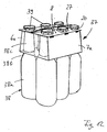
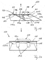
- Fig. 11 and 12 show the application of the invention from FIGS. 9 and 10 apparent carrier 37 after placement on six bottles 38.
- the bottles 38 which may be primarily glass or plastic beverage bottles are those having a substantially cylindrical bottle body 38a, an upwardly adjacent, tapered shoulder portion 38b and a subsequent neck 38c provided with a closure member 39, e.g. B. a conventional crown cork, is closed.
- the carrier 37 is placed from above on six, standing in two rows of bottles 38 that the six in the bottom part 5 and in the cover parts 8, 9 formed openings 24, 17 and 22 (FIGS. Fig. 2 ) are aligned coaxially with the closure elements 39, in particular Fig. 11 shows.
- the ceiling parts 8, 9 By pressure on the ceiling parts 8, 9, these are then pushed down over the closure elements 39, so that the closure elements 39, the under-grip segments 20 of the ceiling portion 8 conically spread until they engage after overflowing the closure elements 39 below the lower edges.
- the diameters of the peripheral lines 18, 19 and 23 of the openings 17 and 22 and the radial lengths of the lower grip segments 20 are selected so that the lower grip segments 20 in the attached state (FIG. Fig. 11, 12th ) abut against the lower edges of the closure elements 39, are spread apart by less than 90 ° and are resiliently biased radially inward, which is still supported by the peripheral edges 23 of the openings 22.
- the diameters of the third openings 24 of the bottom part 5 are selected such that they rest at locations on shoulder areas 38b of the bottles 38 whose distances from the lower edges of the closure elements 39 are smaller than the sum of the heights h1 and h2 of the side panel sections 6a , 6b and 7a, 7b ( Fig. 1 ) corresponds. Therefore, it is necessary during assembly of the support 37, the side parts 6, 7, depending on the case more or less strong around the fold lines 15, 16 (FIG. Fig. 1 ) resiliently buckling. This is in Fig. 11 indicated by the achievable extreme position in which the fold lines 15, 16 come to rest practically on the underside of the lower ceiling part 9.
- the carrier 37 is made of kraft cardboard, but nevertheless flexible in itself, results in this way, regardless of any manufacturing and / or bottle tolerances a tight fit.
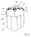
- Fig. 13 and 14 show the application of the blank 32 according to Fig. 2 and the carrier 37a produced therewith Fig. 8 , the up to the additional cover parts 33 according to the carrier 37 after Fig. 11 and 12 equivalent.
- the cover 33 in the off Fig. 3 apparent state of the prefabricated blank 32 at least one opening 24a (FIG. Fig. 2 ) of the bottom part 5, they are automatically erected during insertion of a bottle neck 38c in the opening 24a and pivoted outwardly.
- the dimensioning may preferably be selected so that the cover 33 are erected upright in a nearly vertical position relative to the bottom part 5 ( Fig. 14 ).
- the cover 33 also in the handling of the filled with the bottles 38 Carrier 37a in the off Fig. 13 and 14 remain apparent position, they and the side panels 6, 7 according to the invention with cooperating connection means, preferably provided for mutual latching locking elements.
- These include, in particular Fig. 2 and 14 show, at least one attached to a cover 33, outwardly projecting latching tongue 40 and one of these, formed in a side part 6, 7, for receiving the latching tongue 40 specific recess 41.
- each cover 33 and each side member 6 is on each side , 7 each such a locking tongue 40 and recess 41 are present.
- the arrangement is preferably made so that the erection of the cover members 33 when placed on the bottle 38 automatically until the automatic engagement of the locking tongues 40 in the recesses 41 and therefore no additional step is required for this.
- the cover parts 33 and at least one of the cover parts 8, 9 with further cooperating connecting means.
- the farthest from the longitudinal axis 2 ends of the cover 33 at least one respective clamping tongue 42 which is foldable about a longitudinal axis 2 parallel, twelfth fold line 43 and formed so that they automatically when erecting the respective cover 33 against an associated clamping surface sets, which is expedient here the bottom part 5 facing bottom of the lower ceiling part 9.
- This also allows a substantially perpendicular to the bottom part 5 extended position of the cover 33 is secured during use of the carrier 37 a.
- the cover 33 may on the one hand as additional advertising media, on the other hand z. B. can be used as token by being marked accordingly and arranged tear-off along the perforated fold lines 34.
- the cover 33 but also as an outer cap for between them and the associated bottles 38 introduced gift items such. B. toy cars od. Like. Serve.
- the cover parts 33 preferably have finger openings, not shown which can normally be closed by depressible tongues.
- the cover members 33 allow effective light protection, if the bottles 38 od with a photosensitive liquid. Like. Should be filled.
- the cover members 33 may also be provided with a standard bar code valid for the entire portable bottle set to prevent the bottle carrier 37a from being erroneously scanned marks on the bottles 38 itself upon scanning.
- the blank 1 can be provided with tear-open bottles 44, which can be torn open along perforations 45 produced during the punching process, thereby removing the bottles 38 from the finished carriers 37 (FIG. Fig. 11 and 12 ) facilitate.
- the perforations 45 suitably lead from parts intended for gripping the tear-open tabs to selected openings 17 and 22, respectively.
- the described fold lines 10 to 12, 14 to 16, 19, 28 to 30, 34 and 43 may be imaginary lines, although they are conveniently made in any manner by embossing, creasing, creasing and cutting or otherwise. Although theoretically they may be absent, they greatly facilitate the folding of the various parts and the spreading of the undergrip segments 20. In addition, it may be appropriate to form the fold lines so that they promote folding of selected parts of the blanks 1 and 32 in predetermined preferred directions. This is true as above based on the Fig. 5 and 6 has been explained, in particular for the gripping parts 27 formed from the handle portions 27a, 27b, preferably not in the erected state of the carrier 37, as in Fig.
- FIG. 13 and 14 is shown to be perpendicular to the carrier top, but should form a comparatively small angle with this.
- Fig. 11 and 12 shown for the carrier 37, the carrier 37 a after Fig. 13 and 14 also corresponds to the difference that he has no cover 33.
- Fig. 11 schematically indicated by a bottom 46 of such a crate. Show against it Fig. 13 and 14 in that the handle part 27 in the fully erected state forms a comfortably graspable carrying handle.
- Fig. 15 shows analogously to Fig. 1 and 2 a further embodiment of a blank 101 according to the invention in a flat lying state. Since this most of the features of the blank 1 according to Fig. 1 below, parts of the 15 to 26 as far as they are the same or substantially the same as corresponding parts in Fig. 1 to 14 are provided with increased by 100 reference numerals. In addition, to avoid repetition, these parts will be described below only if necessary for the purposes of the invention.
- a bottom portion 105 has two spaced in the direction of a longitudinal axis 102 bottom portions 105a and 105b, wherein one bottom portion 105a at a fold line 110 and the other bottom portion 105b ends at a fold line 111.
- a handle part 127 intended for the formation of a carrying handle is arranged according to the invention, which has two contiguous handle part sections 127a, 127b lying adjacent to one another in the direction of the longitudinal axis 102, the mutually facing side edges along a substantially perpendicular to the longitudinal axis 102 eighth Fold line 128 are connected miteinder.
- the one handle portion 127 a at its other side edge along a ninth fold line 129 with the in Fig. 15 left bottom portion 105a and the other handle portion 127b at its other side edge along a tenth fold line 130 with the in Fig. 15 right bottom portion 105b connected, wherein the two fold lines 129 and 130 are also arranged substantially perpendicular to the longitudinal axis 102.
- a first stage of the process At least one of the two handle portions 127 a and 127 b z. In a zone 135 in Fig. 15 on the invisible back of the blank 101 and therefore is indicated by dashed crosses, covered with a suitable adhesive. Thereafter, the two handle portions 127a, 127b are folded by about 90 ° to the ninth and tenth folding line 129 and 130 after from.
- the fold lines 129, 130 at the same time in the direction of the longitudinal axis 102 to mutual contact moves toward each other to fold the handle portions 127a, 127b by about 180 ° about the eighth fold line 128 connecting them to the rear, until they with their backs to each other lie and are firmly connected to each other by means of the adhesive in the zone 135.
- Fig. 16 Above the ceiling portion 108 is a front view in the direction of an arrow b in Fig. 16 for the state obtained after folding.
- the two fold lines 129, 130 are now directly next to each other, so that they form a pivot axis about which the handle member 127 can be pivoted relative to the rest of the blank 101.
- the handle portion 127 as well as Fig. 16 can recognize to this pivot axis z. B. pivoted to the left that it rests substantially completely on the associated areas of the bottom part 105 and the side part 106.
- a further process step ( Fig. 17 ) will be in Fig. 16 right side portion 107 and the adjacent second ceiling portion 109 preferably by about 180 ° together about the second fold line 111 and in Fig. 16 folded over from and above, whereby the inside of the side portion 107 on the bottom portion 105b and a part of the handle portion 127b and the inside of the second ceiling portion 109 on the remaining part of the handle portion 127b and the second side portion 106 comes to rest.
- the dimensions of the various parts z. B. selected so that after this process step, the side edge 104 a of the ceiling portion 109 is above the third fold line 112.
- the ceiling part 109 is on its now upper side in the range of glue zones 136, which in Fig. 17 indicated by crosses, provided with an adhesive. Subsequently, the ceiling part 108 is rotated by about 180 ° about the third fold line 112 and in Fig. 17 folded over from the top or and placed on the surface covered with adhesive of the second ceiling portion 109. Thereafter, by applying pressure to the ceiling portion 108 and curing the size of the glue, a strong bond is made between the two ceiling portions 108, 109 by gluing. It is how Fig. 18 shows, the arrangement is such that the edge lines 123 of the openings 122 come to lie coaxially over the edge lines 119 of the openings 117.
- the width of the ceiling part 108 measured in the direction of the longitudinal axis 102 preferably corresponds substantially to the width of the ceiling part 109.
- the grip part 127 is now arranged between the second ceiling part 109 and the first side part 106 and the bottom part portion 105a.
- the arrangement is preferably made so that the two handle portions 127a, 127b in a preferred, from Fig. 16 apparent swivel direction are biased and in the state after Fig. 16 are not perpendicular to the top of the bottom portion 105, but automatically form an angle with this, preferably substantially smaller than 90 °.
- This is z. B. achieved in that the fold lines 129 and 130, with which the handle portions 127a, 127b adjoin the bottom portions 105a, 105b, are suitably designed as pure creasing or creasing / cutting lines or combinations thereof.
- the measured in the direction of the longitudinal axis 102 height of the two substantially equal grip portions 127a, 127b is sufficiently larger than the measured in the same direction height of the two equal-sized side portions 106 and 107 as explained below.
- Fig. 18 is a front view from the direction of an arrow x in Fig. 18 shows, in the direction of the arrows drawn there are removed from each other, until in a known manner ( DE 40 34 069 A1 ) a bottle carrier 137 is created ( Fig. 21, 22nd ).
- the arrangement is such that now also the third, located in the bottom part 105 openings 124 on the openings 117, 122 are aligned coaxially.
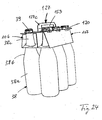
- the two ceiling parts 108, 109 each have a slot 146 or 147 running essentially perpendicular to the longitudinal axis 102 in central areas (eg. Fig. 16 ), which when erecting the blank 101 in the off FIGS. 19 and 20 can be seen overlying each other so that the handle portion 127 with a tapered front portion 127c ( Fig. 20 ) can be pushed through them.
- the front portion 127c is formed by the fact that the handle portions 127a, 127b are provided at their front of the fold lines 129, 130 front end with corresponding tapers, such. B. Fig. 15 shows. Since the height of the handle portions 127a, 127b ( Fig.
- the handle part 127 stands after erecting the blank 101 to the finished carrier 137 (FIG. Fig. 20 ) so much over the tops of the upper ceiling portion 108, that it like the handle portion 27 in Fig. 13 can be taken during transport of bottles.
- the front sections 127c also form, with the areas of the handle section sections 127a, 127b lying behind, a shoulder 127d (FIG. Fig. 20 ), which lie when pulling on the handle portion 127 from below against the edge of the slot 147 and thereby prevent the bottom part 105 can be pulled up to the ceiling portion 109 zoom.
- the handle member 127 when erecting the blank 101 is more or less automatically guided through the slots 146, 147 to the outside.
- two measures are provided according to the invention. On the one hand are imaginary, perpendicular to the longitudinal axis 102 extending center lines of the slots 146, 147 slightly off-center and arranged in the ceiling parts 108, 109 such that a parallel thereto delimiting line 146a of the slot 146 (FIG. Fig.
- each sector is only along a narrow, the fold line 128 facing fixed point 149, the z. B. is only one to two millimeters wide, connected to the handle portion 127 b, but otherwise the punching of the blank 101 has been provided with an all-round, punched-through contour 150.
- the tabs 148 are made effective by the inside of the second cover part 109 before folding, ie before the transition from the state according to FIG Fig. 16 in the state according to Fig. 17 , in the area of two in Fig. 16 indicated glue zones 151 is covered with an adhesive. After folding over of the second cover part 109, therefore, the tabs 148 in regions 148a (FIG. Fig. 16 ) is firmly connected to the inside 109 (see also the enlarged illustration in FIG Fig. 19 ). This in turn has the consequence that when erecting the blank 101 and thereby taking place of the cover parts 108, 109 from the bottom part 105 in the direction of in Fig.
- a particular advantage of the Aufricht Anlagen described is that the blanks 101 can also be easily erected by machine.
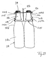
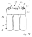
- the fully erected carrier 137 is off FIGS. 21 and 22 seen.
- the handle portion 127 is now disposed in the center of the bottom portion 105 and substantially perpendicular thereto, with an upper portion projecting outwardly beyond the ceiling portions 108, 109 and forming a readily graspable handle.
- FIGS. 23 to 25 show the application of the invention from FIGS. 21 and 22 apparent carrier 137 after placement on six bottles 38. To avoid repetition is so far on the description of the Fig. 11 to 14 directed.
- Fig. 26 shows Fig. 26 that in the embodiment according to FIGS. 15 to 25 the bottom portion 105 is preferably formed so flexible that it is automatically pushed wedge-shaped down to the required extent in the attack of the bottom 46 to the handle portion 127, provided that the handle portion 127 is higher than the distance of the bottom 46 when stacking beverage crates. A lateral pivoting away of the handle portion 127 is therefore contrary to Fig. 11 not mandatory.
- the handle parts 27 and 127 or handle portions 27a, 27b and 127a, 127b are otherwise such.
- B. Fig. 5 . 14 . 24 and 25 show, provided with through openings 153 for the fingers.
- the two handle portions 27a, 27b and 127a, 127b are preferably firmly connected to each other, which is preferably done by gluing as in the connection of the ceiling or floor parts 8a, 8b and 105a, 105.
- bottles in the context of the present invention, all containers, ie also can bottles, glass bottles od. Like. Includes, which are formed in their shoulder and neck portions as the described bottles 38 and therefore with the described carriers 37, 37 a and 137 are packaged can.
- the bottle bodies 38a may of course also have other shapes, in particular deviating from the illustrated cylindrical shape.
- other kraft cardboard can continue to be used. For example, basis weights of 400-450 g / m 2 for 11 bottles, of 360-420 g / m 2 for bottles of 0.51 content and of 300-360 g / m 2 for bottles of 0.33 l are suitable.
- Fig. 27 and 28 the example of a substantially the Fig. 1 corresponding blank shown.
- the grip portion 27a in Fig. 28 on the other hand, the grip portion 27b is provided with one reinforcing strip 155 each.
- This consists z. B. from a thin strip or tape of a sufficiently hard plastic, which is preferably connected to the inner, not visible in use bottom of the handle portion 27 a and 27 b, for example by gluing.
- Fig. 27 .
- the reinforcing strip 155 can extend over substantially the entire length of the handle section 27a, 27b, measured transversely to the longitudinal axis 2, and have a width in the direction of the longitudinal axis 2 substantially equal to the distance of the fold line 28 from a border 156 parallel thereto , 157 corresponds to the passage opening 153 formed in the respective grip part section 27a, 27b.
- the reinforcing strip 155 is suitably provided on a broad side with a self-adhesive surface, so that it can be easily attached to the finished blank.
- the weight per unit area of the carton provided for the carrier can be reduced by approximately 15% when the reinforcing strip 155 is used, which of course could also be applied to both handle sections 27a and 27b.
- the reinforcing strip 155 increases the carrying stability with otherwise the same conditions by at least about 40%, so that the handle member 27 under load even in comparatively thin and narrow, located above the passage openings 153 web portions of the handle parts 27 does not crack. Particularly with carriers for glass bottles with contents of 0.51 to 1.51, this safety aspect is of particular importance.
- Corresponding reinforcing strips can after blanks Fig. 2 and 15 be provided.
- FIG. 27 to 29 be provided by means of positively acting locking means.
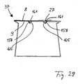
- Fig. 27 and 28 show for this purpose on the ceiling sections 8a and 8b, which come to lie in the finished support 37 on the ceiling part 9, locking tabs 158 are provided, which are each embossed or prepunched along an outline 159, but along a rear, transverse to the longitudinal axis of the second extending bending line 160 remain firmly connected to the blank 1.
- These locking tabs 158 may, for. B. folded with a puncture dome inward.
- the blank material within the recesses 161 is not removed, but merely pre-punched or pre-stamped along a contour 163, so that it remains connected to the blank 1 along a bending line 164 extending transversely to the longitudinal axis 2 and a securing tab 165 (FIG. Fig. 29 ). Therefore, if an associated locking tab 158 is bent downwards by about 90 ° after the carrier 37 has been produced, then the securing tab 165 is also pressed downwards until it snaps behind the locking tab 158, as in FIG Fig. 29 is clearly visible. As a result, a subsequent jumping out of the locking tab 158 under load of the handle member 27 is reliably prevented.
- the locking tabs 158 and the retaining tabs 165 may, as Fig. 27 to 29 show, be foldable or bendable in different directions.
- the locking means which can also be designed and arranged differently than in Fig. 27 to 29 is shown, with particular advantage in the embodiments according to Fig. 1 to 14 If necessary, but can also in the embodiment according to 15 to 26 be used.
- the blanks 1, 32 and 101 and their openings 17, 22 and 24 or 117, 122 and 124 to other closure elements for. B. screw caps, adapted or designed so that the lower grip segments 20, 120 not at their lower edges, but create radially outwardly projecting support rings, which are often mounted below the closure elements on the bottle necks in particular plastic bottles.
- the undergrip segments 20, 120 can also be omitted altogether if the edges delimiting the openings 17, 117 are sufficiently flexible.
- another design of the undergrip segments 20, 120 is possible by z. B. instead of dividing lines 21, 121 larger spaces between the individual segments are provided.
- the various blank fields can have other geometrical shapes within certain limits, e.g. B. be provided with rounded corners or other, product-related modifications.
Landscapes
- Engineering & Computer Science (AREA)
- Mechanical Engineering (AREA)
- Packages (AREA)
- Cartons (AREA)
Abstract
Description
Die Erfindung betrifft einen Zuschnitt der im Oberbegriff des Anspruchs 1 angegebenen Gattung.The invention relates to a blank of the type specified in the preamble of
Zuschnitte dieser Art zur Herstellung von ein- oder mehrreihigen Trägem für Flaschen, insbesondere Getränkeflaschen, sind in verschiedenen Varianten bekannt (
Zur Erleichterung des Tragens und Herausnehmens gefüllter Flaschenträger aus Getränkekisten od. dgl. sind die Deckenteile der Zuschnitte in der Regel mit Tragelementen in Form von vorgestanzten, wegdrückbaren Zungen versehen, die im weggedrückten Zustand zum Einführen der Finger bestimmte, als Tragehilfen wirksame Löcher und zwischen diesen angeordnete Stege stehen lassen. Da das Ergreifen der Flaschenträger jedoch nur mit zwei Fingern einer Hand möglich ist, werden derartige Tragehilfen oft als unbequem empfunden, zumal mit vier, sechs oder mehr Flaschen gefüllte Träger ein nicht unbeträchtliches Gewicht haben.To facilitate carrying and removing filled bottle carrier from beverage crates od. Like. The ceiling parts of the blanks are usually provided with support elements in the form of pre-punched, wegdrückbaren tongues in the weggedrückten state for insertion of the fingers certain, as a support effective holes and stand between them webs. However, since the gripping of the bottle carrier is possible only with two fingers of one hand, such carrying aids are often perceived as uncomfortable, especially with four, six or more bottles filled carrier have a not inconsiderable weight.
Daneben sind Zuschnitte zur Herstellung von einreihigen Flaschenträgern bekannt, die je ein Tragelement in Form eines über ein oberes Deckenteil vorstehenden Traggriffs aufweisen (
Nicht ausreichend stabil sind auch andere bekannte, einreihige Flaschenträger (z. B.
Schließlich sind auch bereits mit Traggriffen versehene Träger bekannt, die zwei Reihen von Flaschen aufnehmen können. Bei diesen Trägern grenzen jedoch innerhalb des Zuschnitts zwei den Traggriff bildende Griffteilabschnitte so ungünstig an andere Abschnitte der Zuschnitte, daß entweder eine maschinelle Herstellung der Träger aus den Zuschnitten praktisch unmöglich ist oder keine zwei übereinander anzuordnende Deckenteile vorgesehen werden können (
Letzteres gilt auch für bekannte Zuschnitte (
Ausgehend davon liegt der Erfindung das technische Problem zugrunde, einen zwei- oder mehrreihigen Zuschnitt der eingangs bezeichneten Gattung in der Weise mit mittig angeordneten Traggriffen zu versehen, daß sich eine stabile, einfache Konstruktion ergibt, die dem Gewicht von 2 x 2, 2 x 3 oder mehr gefüllten Flaschen standhalten kann.Based on this, the technical problem underlying the invention is to provide a two- or multi-row blank of the type described above in the manner with centrally arranged carrying handles that results in a stable, simple construction, the weight of 2 x 2, 2 x 3 or can withstand more filled bottles.
Zur Lösung dieser Aufgabe dienen die kennzeichnenden Merkmale des Anspruchs 1.To solve this problem, the characterizing features of
Durch die Erfindung wird der Vorteil erzielt, daß die den Traggriff bildenden Griffteilabschnitte des Zuschnitts so in das Decken- oder Bodenteil integriert sind, daß sowohl alle zur Aufnahme der Flaschenhälse bestimmten Öffnungen geschlossene Konturen aufweisen als auch im fertigen Träger zwei übereinander liegende Deckenteile vorhanden sind. Damit ist es möglich, insbesondere solche Zuschnitte bzw. daraus hergestellte Flaschenträger mit über das obere Deckenteil hinausragenden, mit der ganzen Hand erfaßbaren Traggriffen zu versehen, die sich bisher im Hinblick auf die Ausbildung der Untergriffssegmente als besonders stabil erwiesen haben (z. B.
Weitere vorteilhafte Merkmale der Erfindung ergeben sich aus den Unteransprüchen.Further advantageous features of the invention will become apparent from the dependent claims.
Die Erfindung wird nachfolgend in Verbindung mit den beiliegenden Zeichnungen an Ausführungsbeispielen näher erläutert. Es zeigen:
-
Fig. 1 eine Draufsicht auf einen erfindungsgemäßen, zur Herstellung eines zweireihigen Flaschenträgers bestimmten Zuschnitt mit einem in ein erstes Deckenteil integrierten Traggriff in einem flach liegenden, ungefalteten Zustand; -
Fig. 2 eine derFig. 1 entsprechende Ansicht eines erfindungsgemäßen, zusätzlich mit zwei Abdeckteilen versehenen Zuschnitts; -
Fig. 3 eine Draufsicht des Zuschnitts gemäßFig. 2 nach dem Einklappen der beiden Abdeckteile und von zwei in dem ersten Deckenteil angeordneten Traggriffabschnitten; -
Fig. 4 eine Draufsicht des Zuschnitts gemäßFig. 1 nach dem Einklapen von zwei im ersten Deckenteil angeordneten Traggriffabschnitten sowie nach dem zusätzlichen Einklappen eines zweiten Deckenteils und eines daran angrenzenden Seitenteils; -
Fig. 5 eine Draufsicht des Zuschnitts gemäßFig. 4 nach dem zusätzlichen, zu einem fertigen Träger führenden Einklappen des ersten Deckenteils mit den daran angrenzenden Traggriffabschnitten; -
Fig. 6 und 7 schematisch je eine Vorderansicht eines fertigen Flaschenträgers bei Anwendung des Zuschnitts gemäßFig. 1 im flach liegenden bzw. bereits halb aufgerichteten Zustand; -
Fig. 8 eine derFig. 7 entsprechende Ansicht eines fertigen, bereits halb aufgerichteten Flaschenträgers bei Anwendung des Zuschnitts gemäßFig. 2 ; -
Fig. 9 und 10 je eine Vorderansicht und Draufsicht des Trägers nachFig. 6 und 7 im voll aufgerichteten Zustand; -
Fig. 11 und12 je eine Vorderansicht und eine perspektivische Ansicht des Trägers gemäßFig. 9 und 10 nach dem Aufsetzen auf eine Formation von sechs Flaschen; -
Fig. 13 und14 denFig. 11 und12 entsprechende Ansichten eines mit dem Zuschnitt gemäßFig. 2 und8 hergestellten Trägers nach dem Aufsetzen auf eine Formation von sechs Flaschen; -
Fig. 15 eine Draufsicht auf ein zweites Ausführungsbeispiel eines erfindungsgemäßen Zuschnitts mit einem in ein Bodenteil integrierten Traggriff in einen flach liegenden, ungefalteten Zustand; -
Fig. 16 eine derFig. 15 entsprechende Draufsicht des Zuschnitts nach dem Einklappen von zwei in das Bodenteil integrierten Traggriffabschnitten; -
Fig. 17 eine Draufsicht des Zuschnitts gemäßFig. 16 nach dem zusätzlichen Einklappen eines zweiten Deckenteils und eines mit diesem verbundenen Seitenteils; -
Fig. 18 eine Draufsicht des Zuschnitts gemäßFig. 17 nach dem zusätzlichen, zu einem fertigen Flaschenträger führenden Einklappen eines ersten Deckenteils; -
Fig. 19 eine vergrößerte, schematische Vorderansicht in Richtung eines Pfeils x inFig. 18 auf einen Teil eines fertigen, bereits teilweise aufgerichteten Flaschenträgers bei Anwendung des Zuschnitts gemäßFig. 18 ; -
Fig. 20 einen schematischen Schnitt längs der Linie A-A derFig. 19 ; -
Fig. 21 und 22 je eine Vorderansicht und Draufsicht des Trägers nachFig. 15 bis 19 im voll aufgerichteten Zustand; -
Fig. 23 bis 25 je eine Vorderansicht, perspektivische Ansicht und Seitenansicht des Trägers gemäßFig. 21 und 22 nach dem Aufsetzen auf eine Formation von sechs Flaschen; -
Fig. 26 eine derFig. 23 entsprechende Vorderansicht bei etwas eingedrücktem Traggriff; -
Fig. 27 und28 je eine Draufsicht auf einenFig. 1 entsprechenden, jedoch mit Verstärkungsstreifen und Verriegelungsmitteln versehenen Zuschnitt; und -
Fig. 29 einen schematischen Schnitt längs der Linie XXIX-XXIX derFig. 10 durch einen mit den Verriegelungsmitteln nachFig. 27 und28 versehenen Träger.
-
Fig. 1 a plan view of an inventive, intended for the production of a double-breasted bottle carrier blank with a built-in a first cover part carrying handle in a flat, unfolded state; -
Fig. 2 one of theFig. 1 corresponding view of an inventive, additionally provided with two cover blank blank; -
Fig. 3 a plan view of the blank according toFig. 2 after folding the two cover parts and two in the first cover part arranged Traggriffabschnitten; -
Fig. 4 a plan view of the blank according toFig. 1 after collapsing two arranged in the first cover part carrying handle sections and after the additional folding of a second ceiling part and an adjacent side part; -
Fig. 5 a plan view of the blank according toFig. 4 after the additional leading to a finished carrier collapsing the first ceiling portion with the adjacent thereto handle portions; -
6 and 7 schematically a front view of a finished bottle carrier when using the blank according toFig. 1 in the flat or semi-erect condition; -
Fig. 8 one of theFig. 7 corresponding view of a finished, already half-erected bottle carrier when using the blank according toFig. 2 ; -
FIGS. 9 and 10 depending on a front view and top view of thewearer 6 and 7 in the fully erect condition; -
Fig. 11 and12 depending on a front view and a perspective view of the carrier according toFIGS. 9 and 10 after putting on a formation of six bottles; -
Fig. 13 and14 theFig. 11 and12 corresponding views of the blank according toFig. 2 and8th prepared carrier after placing on a formation of six bottles; -
Fig. 15 a plan view of a second embodiment of a blank according to the invention with a built-in bottom part carrying handle in a flat, unfolded state; -
Fig. 16 one of theFig. 15 corresponding plan view of the blank after the folding of two integrated in the bottom part carrying handle sections; -
Fig. 17 a plan view of the blank according toFig. 16 after additionally folding in a second ceiling part and a side part connected thereto; -
Fig. 18 a plan view of the blank according toFig. 17 after the additional leading to a finished bottle carrier collapsing a first ceiling part; -
Fig. 19 an enlarged, schematic front view in the direction of an arrow x inFig. 18 on a part of a finished, already partially raised bottle carrier when using the blank according toFig. 18 ; -
Fig. 20 a schematic section along the line AA ofFig. 19 ; -
FIGS. 21 and 22 depending on a front view and top view of thewearer 15 to 19 in the fully erect condition; -
FIGS. 23 to 25 depending on a front view, perspective view and side view of the carrier according toFIGS. 21 and 22 after putting on a formation of six bottles; -
Fig. 26 one of theFig. 23 corresponding front view with slightly pushed in carrying handle; -
Fig. 27 and28 depending on a plan view of aFig. 1 corresponding but provided with reinforcing strips and locking means blank; and -
Fig. 29 a schematic section along the line XXIX-XXIX theFig. 10 by one with the locking means afterFig. 27 and28 provided carrier.
Das Grundelement ist in eine Mehrzahl von Feldern unterteilt und enthält insbesondere ein Bodenteil 5, ein in
Die Teile 5 bis 9 sind durch vorzugsweise im wesentlichen senkrecht zur Längsachse 2 verlaufende, gedachte Faltlinien voneinander getrennt, die zur Erleichterung des weiter unter erläuterten Faltens der verschiedenen Teile aber auch je nach Zweckmäßigkeit aus bereits beim Stanzen angebrachten Prägungen, Rillen, kombinierten Rill/Schneid-Linien od. dgl. bestehen können. Insbesondere sind zwischen dem Bodenteil 5 und den beiden Seitenteilen 6, 7 eine erste Faltlinie 10 und eine zweite Faltlinie 11, zwischen dem ersten Seitenteil 6 und dem ersten Deckenteil 8 eine dritte Faltlinie 12 und zwischen dem zweiten Seitenteil 7 und dem zweiten Deckenteil 9 eine vierte Faltlinie 14 vorgesehen. Schließlich können die beiden Seitenteile 6 und 7 in je zwei parallel zur Längsachse 2 nebeneinanderliegende Seitenteilabschnitte 6a, 6b bzw. 7a, 7b unterteilt sein, die vorzugsweise durch senkrecht zur Längsachse 2 verlaufende fünfte und sechste, ebenfalls beim Stanzvorgang angebrachte Faltlinien 15 und 16 voneinander getrennt sind. Dabei besitzen, jeweils in Richtung der Längsachse 2 betrachtet, die an das Bodenteil 5 grenzenden Seitenteilabschnitte 6a, 7a eine vergleichsweise große Höhe h1, während die an die Deckenteile 8, 9 grenzenden Seitenteilabschnitte 6b, 7b eine vergleichsweise geringe Höhe h2 haben.The
Das zweite Deckenteil 9 weist in zwei vorzugsweise senkrecht zur Längsachse 2 verlaufenden Reihen mehrere, im Ausführungsbeispiel je drei entsprechend der zugeordneten Flaschenform und -größe beabstandete erste Öffnungen 17 auf, deren Umfangslinien bzw. Ränder 18 von konzentrischen, vorzugsweise als siebente Faltlinien ausgebildeten, geschlossenen Umfangslinien 19 umgeben sind. Zwischen den beiden Umfangslinien 18 und 19, d. h. in den die Öffnungen 17 umgebenden Randzonen, weist der Zuschnitt 1 jeweils eine Mehrzahl von in Umfangsrichtung neben einander liegenden Sektoren 20 auf, die durch radial verlaufende, vorzugsweise beim Stanzvorgang angebrachte Trennlinien 21 voneinander getrennt und daher nur längs der Umfangslinien 19 mit dem Zuschnitt 1 verbunden sind. Die Sektoren 20 bilden sogenannte Untergriffsegmente, die zum Untergreifen der Verschlußelemente od. dgl. von Flaschen dienen, wie weiter unter anhand der
Das erste Deckenteil 8 weist in zwei vorzugsweise senkrecht zur Längsachse 2 verlaufenden Reihen eine der Zahl der ersten Öffnungen 17 entsprechende Anzahl von zweiten Öffnungen 22 auf. Diese sind mit denselben Abständen wie die ersten Öffnungen 17 angeordnet und mit Umfangslinien bzw.Rändern 23 versehen, die vorzugsweise dieselben Durchmesser wie die die ersten Öffnungen 17 umgebenden Umfangslinien 19 aufweisen. Beim Ausführungsbeispiel sind die Umfangslinien 18, 19, 23 kreisförmig ausgebildet, wobei die Umfangslinien 18 der ersten Öffnungen 17 entsprechend der vorgesehenen Anzahl von acht Untergriffsegmenten 20 auch ein Oktogon bilden können.The
Das Bodenteil 5 weist dritte Öffnungen 24 auf, die in gleicher Anzahl wie die ersten und zweiten Öffnungen 17, 22 und in entsprechender Anordnung wie diese vorgesehen sind. Die Öffnungen 24 weisen kreisrunde Umfangslinien 25 und Durchmesser auf, die zweckmäßig etwas größer als die der Öffnungen 22 sind. Außerdem weisen das Bodenteil 5 und das zweite Deckenteil 9 parallel zur Längsachse 2 im wesentlichen gleiche Breiten auf, damit sie in an sich bekannter Weise zur Herstellung eines Flaschenträgers so übereinander angeordnet werden können, daß die Öffnungen 17, 22 und 24 auf einander ausgerichtet sind.The
Zuschnitte der beschriebenen Art sind grundsätzlich bekannt (z.B.
Ein wesentlicher Unterschied zwischen dem erfindungsgemäßen Zuschnitt 1 und den bekannten Zuschnitten besteht darin, daß das erste Deckenteil 8 zwei in Richtung der Längsachse 2 beabstandete Deckenteilabschnitte 8a und 8b aufweist, wobei ein erster Deckenteilabschnitt 8a an der Faltlinie 12 und ein zweiter Deckenteilabschnitt 8b an der Seitenkaten 4b endet. Zwischen den beiden Deckenteilabschnitten 8a, 8b ist außerdem erfindungsgemäß ein Griffteil 27 angeordnet, das zwei zusammenhängende, in Richtung der Längsachse 2 nebeneinander liegende Griffteilabschnitte 27a und 27b aufweist, deren einander zugewandte Seitenkanten längs einer im wesentlichen senkrecht zur Längsachse 2 verlaufenden, achten Faltlinie 28 miteinander verbunden sind. Außerdem ist der eine Griffteilabschnitt 27a an seiner anderen Seitenkante längs einer neunten Faltlinie 29 mit dem innen liegenden Deckenteilabschnitt 8a und zweite Griffteilabschnitt 27b an seiner anderen Seitenkante längs einer zehnten Faltlinie 30 mit dem außen liegenden Deckenteilabschnitt 8b verbunden, wobei die beiden Faltlinien 29 und 30 ebenfalls im wesentlichen senkrecht zur Längsachse 2 angeordnet und vorzugsweise wie die anderen Faltlinien ausgebildet sind.An essential difference between the blank 1 according to the invention and the known blanks is that the
Ein Zuschnitt 32 nach dem Ausführungsbeispiel gemäß
Bei einer besonders bevorzugten Ausführungsform der Erfindung weist der Zuschnitt 32 zwei gleichartige seitliche Abdeckteile 33 auf, die an entgegengesetzten Seiten der Längsachse 2 mit dem Bodenteil 5 verbunden und vorzugsweise spiegelsymmetrisch zur Längsachse 2 ausgebildet sind, so daß die Beschreibung für das eine Abdeckteil 33 in gleicher Weise auch für das andere Abdeckteil 33 gilt.In a particularly preferred embodiment of the invention, the blank 32 has two similar
Die Herstellung eines Flaschenträgers mit Hilfe des Zuschnitts 1 bzw. 32 kann beispielsweise so vorgenommen werden, wie nachfolgend anhand der
In einer ersten Verfahrensstufe (
Gleichzeitig oder auch davor oder danach werden die Abdeckteile 33, soweit sie vorhanden sind, um die elften Faltlinien 34 um mehr als 90°, vorzugsweise um ca. 180°, nach innen umgeklappt, so daß sie danach der in
In einem weiteren Verfahrensschritt (
In einer weiteren Verfahrensstufe wird das Deckenteil 9 auf seiner jetzt oben liegenden Seite im Bereich von Leimzonen 36, die in
Wie
Wie
Die Abdeckteile 33 liegen, sofern sie bei einem Flaschenträger 37a (
Der Träger 37 wird von oben her so auf sechs, in zwei Reihen stehende Flaschen 38 aufgesetzt, daß die sechs im Bodenteil 5 und in den Deckenteilen 8, 9 ausgebildeten Öffnungen 24, 17 und 22 (
Zur stabilen Festlegung des Trägers 37 auf den Flaschen 38 dienen dabei insbesondere zwei Maßnahmen. Zum einem sind die Durchmesser der Umfangslinien 18, 19 und 23 der Öffnungen 17 und 22 sowie die radialen Längen der Untergriffsegmente 20 so gewählt, daß die Untergriffsegmente 20 im aufgesetzten Zustand (
Da die Abdeckteile 33 in dem aus
Damit die Abdeckteile 33 auch bei der Handhabung des mit den Flaschen 38 gefüllten Trägers 37a in der aus
Alternativ oder zusätzlich ist es möglich, die Abdeckteile 33 und wenigstens eines der Deckenteile 8, 9 mit weiteren zusammenwirkenden Verbindungsmitteln zu versehen. Hierzu weisen beispielsweise gemäß
Die Abdeckteile 33 können einerseits als zusätzliche Werbeträger, andererseits z. B. als Wertmarken verwendet werden, indem sie entsprechend gekennzeichnet und längs der perforierten Faltlinien 34 abreißbar angeordnet werden. Außerdem können die Abdeckteile 33 aber auch als äußere Verschlußdeckel für zwischen sie und die zugehörigen Flaschen 38 eingebrachte Geschenkartikel wie z. B. Spielzeugautos od. dgl. dienen. Um die Geschenkartikel leicht aus dem Träger 37a herausnehmen zu können, weisen die Abdeckteile 33 vorzugsweise nicht dargestellte Fingeröffnungen auf, die normalerweise durch eindrückbare Zungen verschlossen sein können. Weiterhin ermöglichen die Abdeckteile 33 einen wirksamen Lichtschutz, falls die Flaschen 38 mit einer lichtempfindlichen Flüssigkeit od. dgl. gefüllt sein sollten. Schließlich können die Abdeckteile 33 auch mit einem üblichen, für den gesamten tragbaren Flaschensatz gültigen Barcode versehen werden, um zu verhindern, daß beim Abtasten der Flaschenträger 37a irrtümlich auf den Flaschen 38 selbst befindliche Markierungen abgetastet werden.The
Wie insbesondere
Bei den beschriebenen Faltlinien 10 bis 12, 14 bis 16, 19, 28 bis 30, 34 und 43 kann es sich um gedachte Linien handeln, obwohl sie zweckmäßig in an sich beliebiger Weise durch Prägen, Rillen, Rillen und Schneiden oder sonstwie hergestellt werden. Theoretisch können sie zwar auch fehlen, doch erleichtern sie das Falten der verschiedenen Teile und das Aufspreizen der Untergriffsegmente 20 erheblich. Außerdem kann es zweckmäßig sein, die Faltlinien so auszubilden, daß sie ein Falten von ausgewählten Teilen der Zuschnitte 1 bzw. 32 in vorgegebene Vorzugsrichtungen fördern. Dies gilt, wie oben anhand der
Das Ausführungsbeispiel nach
Die Herstellung eines Flaschenträgers mit Hilfe des Zuschnitts 101 kann beispielsweise so vorgenommen werden, wie nachfolgend anhand der
In einer ersten Verfahrensstufe (
In einem weiteren Verfahrenschritt (
In einer weiteren Verfahrensstufe wird das Deckenteil 109 auf seiner jetzt oben liegenden Seite im Bereich von Leimzonen 136, die in
Wie
Der aus
Damit das Griffteil 127 für den späteren Gebrauch nutzbar ist, weisen die beiden Deckenteile 108, 109 in mittleren Bereichen je einen im wesentlichen senkrecht zur Längsachse 102 verlaufenden Schlitz 146 bzw. 147 (z. B.
Gemäß eines besonders bevorzugten Ausführungsbeispiel der Erfindung ist vorgesehen, die Anordnung so zu treffen, daß das Griffteil 127 beim Aufrichten des Zuschnitts 101 mehr oder weniger selbsttätig durch die Schlitze 146, 147 nach außen geführt wird. Dazu sind erfindungsgemäß zwei Maßnahmen vorgesehen. Zum einen werden gedachte, senkrecht zur Längsachse 102 verlaufende Mittellinien der Schlitze 146, 147 etwas außermittig und derart in den Deckenteilen 108, 109 angeordnet, daß eine dazu parallele Begrenzungslinie 146a des Schlitzes 146 (
Die Laschen 148 werden dadurch wirksam gemacht, daß die Innenseite des zweiten Deckenteils 109 vor dem Umfalten, d. h. vor dem Übergang vom Zustand gemäß
Ein besonderer Vorteil der beschriebenen Aufrichthilfe besteht darin, daß die Zuschnitte 101 auch leicht maschinell aufgerichtet werden können.A particular advantage of the Aufrichthilfe described is that the
Der voll aufgerichtete Träger 137 ist aus
Die Griffteile 27 und 127 bzw. Griffteilabschnitte 27a, 27b und 127a, 127b sind im übrigen, wie z. B.
Die Erfindung ist nicht auf die beschriebenen Ausführungsbeispiele beschränkt, die auf vielfache Weise abgewandelt werden können. Zunächst ist klar, daß der Begriff "Flaschen" im Rahmen der vorliegenden Erfindung alle Behälter, d. h. auch Dosenflaschen, Glasflaschen od. dgl. umfaßt, die in ihren Schulter- und Halsabschnitten wie die beschriebenen Flaschen 38 geformt sind und daher mit den beschriebenen Trägern 37, 37a bzw. 137 verpackt werden können. Dabei können die Flaschenkörper 38a natürlich auch andere Formen, insbesondere von der dargestellten Zylinderform abweichende Formen aufweisen. Je nach Zahl und Aufnahmevolumen der Flaschen 38 können weiterhin andere Kraftkartons verwendet werden. Beispielsweise sind Flächengewichte von 400 - 450 g/m2 für 11 - Flaschen, von 360 - 420 g/m2 für Flaschen mit 0,51 Inhalt und von 300 - 360 g/m2 für Flaschen mit 0,33 l geeignet.The invention is not limited to the described embodiments, which can be modified in many ways. First, it is clear that the term "Bottles" in the context of the present invention, all containers, ie also can bottles, glass bottles od. Like. Includes, which are formed in their shoulder and neck portions as the described
Insbesondere bei größeren Flaschen und geringeren Flächengewichten kann es zweckmäßig sein, die Griffteile bzw. die zu ihrer Herstellung dienenden Griffteilabschnitte mit Verstärkungen zu versehen. Dies ist in
Überraschend wurde festgestellt, daß das Flächengewicht des für den Träger vorgesehenen Kartons bei Anwendung des Verstärkungsstreifens 155, der natürlich auch auf beiden Griffteilabschnitten 27a und 27b angebracht werden könnte, um ca. 15 % reduziert werden kann. Umgekehrt erhöht der Verstärkungsstreifen 155 die Tragestabilität bei sonst gleichen Verhältnissen um wenigstens ca. 40 %, so daß das Griffteil 27 bei Belastung auch in vergleichsweise dünnen und schmalen, oberhalb der Durchgriffsöffnungen 153 befindlichen Stegabschnitten der Griffteile 27 nicht reißt. Besonders bei Trägern für Glasflaschen mit Inhalten von 0,51 bis 1,51 ist dieser Sicherheitsaspekt von besonderer Bedeutung.Surprisingly, it has been found that the weight per unit area of the carton provided for the carrier can be reduced by approximately 15% when the reinforcing
Entsprechende Verstärkungsstreifen können bei Zuschnitten nach
Eine weitere vorteilhafte Verstärkung der beschriebenen Träger 1 kann gemäß
In einer zweiten, bevorzugten Variante wird das Zuschnittmaterial innerhalb der Aussparungen 161 nicht entfernt, sondern lediglich längs einer Kontur 163 vorgestanzt bzw. vorgeprägt, so daß es längs einer quer zur Längsachse 2 verlaufenden Biegelinie 164 mit dem Zuschnitt 1 verbunden bleibt und eine Sicherungslasche 165 (
Mit Hilfe der Verriegelungslaschen 158, Aussparungen 161 und ggf. Sicherungslaschen 165 wird in Ergänzung zu der kraftschlüssigen Klebeverbindung eine sehr stabile, formschlüssige Verbindung zwischen den beiden Deckenteilen 8 und 9 geschaffen. Dadurch wird insbesondere bei Anwendung schwerer Flaschen sicher vermieden, daß sich die beiden Deckenteile 8, 9 bei Belastung voneinander lösen.With the help of the locking
Die Verriegelungsmittel, die auch anders ausgebildet und angeordnet sein können, als in
Weiterhin können die Zuschnitte 1, 32 und 101 und deren Öffnungen 17, 22 und 24 bzw. 117, 122 und 124 an andere Verschlußelemente, z. B. Schraubverschlüsse, angepaßt oder so ausgelegt werden, daß sich die Untergriffsegmente 20, 120 nicht an deren Unterkanten, sondern an radial nach außen ragende Tragringe anlegen, die insbesondere bei Kunststoffflaschen häufig unterhalb der Verschlußelemente an den Flaschenhälsen angebracht sind. Weiterhin können die Untergriffsegmente 20, 120 auch ganz weggelassen werden, wenn die die Öffnungen 17, 117 begrenzenden Ränder ausreichend flexibel sind. Auch eine andere Gestaltung der Untergriffsegmente 20, 120 ist möglich, indem z. B. statt der Trennlinien 21, 121 größere Zwischenräume zwischen den einzelnen Segmenten vorgesehen werden. Ferner können die verschiedenen Zuschnittfelder in gewissen Grenzen andere geometrische Formen aufweisen, indem sie z. B. mit abgerundeten Ecken oder sonstigen, produktbezogenen Abänderungen versehen werden. Entsprechendes gilt für die Größe der Abdeckteile 33, die auch kleiner sein könnten, als den offenen Stirnseiten eines aus dem Grundelement des Zuschnitts 32 herstellbaren Trägers entspricht, sowie für die nur beispielhaft beschriebenen Verbindungsmittel, die auch anders als dargestellt ausgebildet sein könnten. Schließlich versteht sich, daß die verschiedenen Merkmale auch in anderen als in den dargestellten und beschriebenen Kombinationen angewendet werden können.Furthermore, the
Claims (33)
- Kraft cardboard blank for producing a multi-row carrier (37, 37a, 137) for bottles (38) provided with closure elements (39) and optionally with support rings, comprising a substantially rectangular and unfolded basic element which lies flat and has a central base part (5; 105), two side parts (6, 7; 106, 107), which adjoin the latter on both sides, two top parts (8, 9; 108, 109), which each adjoin one side part (6, 7; 106, 107), are to be arranged one above the other and are to be adhesively bonded to one another, and a support element, wherein the two top parts (8, 9; 108, 109) and the base part (5, 105) are provided with openings (17, 22, 24; 117, 122, 124), which are arranged in at least two rows and are intended to accommodate necks (38c) of the bottles (38), and the base part (5, 105), the side parts (6, 7; 106, 107) and the top parts (8, 9; 108, 109) are delimited from one another by folding lines (10 to 14 and 110 to 114, respectively) extending substantially perpendicularly to a longitudinal axis (2; 102), characterized in that at least one of the two top parts (8) or the base part (105) has two top- or base-part sections (8a, 8b; 105a, 105b), which are spaced apart from one another in the direction of the longitudinal axis (2; 102) and between which there is arranged a handle part (27; 127) formed from two contiguous handle sections (27a, 27b; 127a, 127b) which can be laid one on the other in order together to form a carrying handle and are each connected to one of the top- or base-part sections (8a, 8b; 105a, 105b) at mutually facing side edges along a folding line (28; 128) arranged substantially perpendicularly to the longitudinal axis (2; 102) and at mutually distant side edges along folding lines (29, 30; 129, 130) likewise extending substantially perpendicularly to the longitudinal axis (2; 102).
- Blank according to Claim 1, characterized in that the two top- or base-part sections (8a, 8b; 105a, 105b) each have one row of the associated openings (22; 124).
- Blank according to either of Claims 1 and 2, characterized in that a first of the two top parts (8) has two top-part sections (8a, 8b) connected by the handle part (27) and, by folding and connecting together the two top parts (8, 9), on the one hand, and positioning the two handle sections (27a, 27b) one on the other, on the other hand, the basic element is prefabricated into a carrier (37, 37a) for the bottles (38) such that the first top part (8) lies on the other, second top part (9) and is connected firmly thereto, whereas the two handle sections (27a, 27b) can be pivoted relative to the first top part (8), on a side remote from the second top part (9), about the folding lines (29, 39) formed by the top-part sections (8a, 8b) in order thereby to form a handle (27) arranged above the first top part (8).
- Blank according to Claim 3, characterized in that the handle sections (27a, 27b) are prestressed such that the handle (27) forms an angle of less than 90° with the top-part sections (8a, 8b) when the carrier (37, 37a) is in the unused state.
- Blank according to Claim 4, characterized in that the prestressing is produced by a corresponding design of the folding lines (29, 30) connecting the handle sections (27a, 27b) to the top-part sections (8a, 8b).
- Blank according to one of Claims 1 to 5, characterized in that the two top-part sections (8a, 8b) have substantially the same widths in the direction of the longitudinal axis (2).
- Blank according to Claim 6, characterized in that the heights of the handle sections (27a, 27b) are smaller than corresponds to the spacings of the folding lines (29, 30), connecting them to the top-part sections (8a, 8b), from centre lines extending through the centres of the openings (22) located in the top-part sections (8a, 8b).
- Blank according to Claim 1 or 2, characterized in that the base part (105) has two base-part sections (105a, 105b) connected by the handle (127) and the top parts (108, 109) are each provided with a slot (146, 147) for the handle (127) to pass through.
- Blank according to Claim 8, characterized in that, by folding and connecting together the two top parts (108, 109), on the one hand, and positioning the handle sections (127a, 127b) one on the other, on the other hand, the basic element is prefabricated into a carrier (137) for the bottles (38) such that the two top parts (108, 109) lie one on the other and are connected firmly together, whereas the two handle sections (127a, 127b) can be pivoted relative to the base part (105), on a side facing towards the top parts (108, 109), about the folding lines (129, 130) formed by the base-part sections (105a, 105b) and form a handle (127) protruding outwards through the slots (146, 147) in the top parts (108, 109).
- Blank according to Claim 8 or 9, characterized in that the two base-part sections (105a, 105b) have substantially the same widths in the direction of the longitudinal axis (102).
- Blank according to one of Claims 8 to 10, characterized in that the heights of the handle sections (127a, 127b), measured in the direction of the longitudinal axis (102), are greater than corresponds to the heights of the side parts (106, 107) measured in the same direction.
- Blank according to one of Claims 8 to 11, characterized in that the slots (146, 147) have centre lines which are arranged parallel to, but outside, imaginary centre lines, arranged perpendicularly to the longitudinal axis (102), of the top parts (108, 109).
- Blank according to one of Claims 8 to 12, characterized in that it is provided with an assembly aid intended for inserting the handle (127) into the slots (146, 147) in the top parts (108, 109).
- Blank according to Claim 13, characterized in that the assembly aid has at least one tab (148) intended for connecting one of the handle sections (127b) to the second top part (109).
- Blank according to Claim 14, characterized in that the tab (148) consists of a sector of the handle section (127b) which is connected to the rest of the handle section (127b) only along a small fixed point (149) on its peripheral contour.
- Blank according to Claim 14 or 15, characterized in that the tab (148) is produced by punching.
- Blank according to one of Claims 1 to 16, characterized in that the two handle sections (27a, 27b; 127a, 127b) are provided with reach-through openings (153).
- Blank according to one of Claims 1 to 17, characterized in that the handle sections (27a, 27b; 127a, 127b) are connected firmly together.
- Blank according to one of Claims 1 to 18, characterized in that the top- or base-part sections (8a, 8b; 105a, 105b) and/or the handle sections (27a, 27b; 127a, 127b) are connected together by adhesive bonding.
- Blank according to one of Claims 1 to 7 and 17 to 19, characterized in that it has at least one lateral covering part (33) which is connected to the base part (5) along a further folding line (34) arranged substantially parallel to the longitudinal axis (2).
- Blank according to Claim 20, characterized in that, in the prefabricated state, the covering part (33) faces an inside of the base part (5) by pivoting through more than 90° about the further folding line (34).
- Blank according to Claim 20 or 21, characterized in that the covering part (33) and the side and/or top parts (6, 7; 8, 9) are provided with interacting connecting means (40, 41, 42).
- Blank according to one of Claims 20 to 22, characterized in that the further folding line (34) is provided with a perforation.
- Blank according to one of Claims 20 to 23, characterized in that the covering part (33) is designed such that and/or in the prefabricated state faces the inside of the base part (5) such that, when it is placed on the bottle necks (38c), it is flapped open laterally thereby.
- Blank according to Claim 24, characterized in that the arrangement is also such that, when the covering part (33) is flapped open, the connecting means (40, 41, 42) automatically come into engagement.
- Blank according to one of Claims 20 to 25, characterized in that it has a covering part (33) on each of the two sides of the longitudinal axis (2).
- Blank according to one of Claims 1 to 26, characterized in that at least one handle section (27a, 27b) is provided with a reinforcement.
- Blank according to Claim 27, characterized in that the reinforcement consists of an adhesively attached reinforcement strip (155).
- Blank according to Claim 27 or 28, characterized in that the reinforcement is formed in a section of web located above the reach-through openings (153).
- Blank according to one of Claims 1 to 28, characterized in that locking means (158, 161) intended for connecting the top parts (8, 9) in a form-fitting manner are provided.
- Blank according to Claim 30, characterized in that the locking means comprise locking tabs (158) provided on the one top part (8) and cutouts (161) accommodating the locking tabs (158) on the other top part (9).
- Blank according to Claim 31, characterized in that the locking means furthermore comprise securing tabs (165), which are assigned to the locking tabs (158) and are formed on the top part (9) comprising the cutouts (161).
- Bottle carrier for bottles (38) provided with closure elements (39) and optionally with support rings, characterized in that it is produced using a blank according to one or more of Claims 1 to 31.
Applications Claiming Priority (2)
| Application Number | Priority Date | Filing Date | Title |
|---|---|---|---|
| DE20316996U | 2003-11-03 | ||
| DE20316996U DE20316996U1 (en) | 2003-11-03 | 2003-11-03 | Cut from kraft cardboard to produce a multi-row bottle carrier |
Publications (3)
| Publication Number | Publication Date |
|---|---|
| EP1528007A2 EP1528007A2 (en) | 2005-05-04 |
| EP1528007A3 EP1528007A3 (en) | 2006-07-12 |
| EP1528007B1 true EP1528007B1 (en) | 2010-10-13 |
Family
ID=31984674
Family Applications (1)
| Application Number | Title | Priority Date | Filing Date |
|---|---|---|---|
| EP04025488A Expired - Lifetime EP1528007B1 (en) | 2003-11-03 | 2004-10-27 | Blanc for forming a carton bottle carrier |
Country Status (4)
| Country | Link |
|---|---|
| EP (1) | EP1528007B1 (en) |
| AT (1) | ATE484461T1 (en) |
| DE (2) | DE20316996U1 (en) |
| MX (1) | MXPA04010261A (en) |
Cited By (38)
| Publication number | Priority date | Publication date | Assignee | Title |
|---|---|---|---|---|
| WO2020122984A1 (en) * | 2018-12-14 | 2020-06-18 | Graphic Packaging International, Llc | Carrier for containers |
| US11014727B2 (en) | 2018-12-14 | 2021-05-25 | Graphic Packaging International, Llc | Carrier for containers |
| US11027904B2 (en) | 2018-12-14 | 2021-06-08 | Graphic Packaging International, Llc | Carrier for containers |
| US11180301B2 (en) | 2018-12-14 | 2021-11-23 | Graphic Packaging International, Llc | Carrier for containers |
| US11261013B2 (en) | 2018-12-14 | 2022-03-01 | Graphic Packaging International, Llc | Carrier for containers |
| USD946419S1 (en) | 2020-06-30 | 2022-03-22 | Graphic Packaging International, Llc | Carrier |
| USD946421S1 (en) | 2018-12-14 | 2022-03-22 | Graphic Packaging International, Llc | Carrier |
| USD946416S1 (en) | 2019-05-30 | 2022-03-22 | Graphic Packaging International, Llc | Carrier |
| US11279540B2 (en) | 2018-09-07 | 2022-03-22 | Graphic Packaging International, Llc | Carrier for a plurality of containers |
| USD946418S1 (en) | 2020-04-27 | 2022-03-22 | Graphic Packaging International, Llc | Carrier |
| USD946420S1 (en) | 2020-06-30 | 2022-03-22 | Graphic Packaging International, Llc | Carrier |
| USD946417S1 (en) | 2020-06-30 | 2022-03-22 | Graphic Packaging International, Llc | Carrier |
| US11286094B2 (en) | 2020-04-27 | 2022-03-29 | Graphic Packaging International, Llc | Carrier for containers |
| USD974923S1 (en) | 2019-05-30 | 2023-01-10 | Graphic Packaging International, Llc | Carrier |
| US11623803B2 (en) | 2018-12-14 | 2023-04-11 | Graphic Packaging International, Llc | Carrier for containers |
| USD983049S1 (en) | 2021-03-24 | 2023-04-11 | Graphic Packaging International, Llc | Carrier for containers |
| US11628994B2 (en) | 2020-09-30 | 2023-04-18 | Graphic Packaging International, Llc | Carrier for containers |
| USD984282S1 (en) | 2021-03-24 | 2023-04-25 | Graphic Packaging International, Llc | Carrier for containers |
| USD984280S1 (en) | 2019-05-30 | 2023-04-25 | Graphic Packaging International, Llc | Carrier |
| USD984266S1 (en) | 2021-03-24 | 2023-04-25 | Graphic Packaging International, Llc | Carrier for containers |
| USD984279S1 (en) | 2019-05-30 | 2023-04-25 | Graphic Packaging International, Llc | Carrier |
| USD1000290S1 (en) | 2021-03-24 | 2023-10-03 | Graphic Packaging International, Llc | Carrier for containers |
| US11840387B2 (en) | 2021-06-09 | 2023-12-12 | Graphic Packaging International, Llc | Carrier for containers |
| US11958673B2 (en) | 2021-07-15 | 2024-04-16 | Graphic Packaging International, Llc | Carrier for containers |
| US12071291B2 (en) | 2021-06-25 | 2024-08-27 | Graphic Packaging International, Llc | Carrier for containers |
| US12103751B2 (en) | 2021-07-08 | 2024-10-01 | Graphic Packaging International, Llc | Carrier for containers |
| US12172780B2 (en) | 2020-04-28 | 2024-12-24 | Graphic Packaging International, Llc | Method and system for attaching articles to a carrier |
| US12195256B2 (en) | 2021-06-29 | 2025-01-14 | Graphic Packaging International, Llc | Carrier for containers |
| USD1063643S1 (en) | 2022-05-11 | 2025-02-25 | Graphic Packaging International, Llc | Carrier for containers |
| USD1063642S1 (en) | 2022-05-11 | 2025-02-25 | Graphic Packaging International, Llc | Carrier for containers |
| USD1063644S1 (en) | 2022-05-11 | 2025-02-25 | Graphic Packaging International, Llc | Carrier for containers |
| USD1064848S1 (en) | 2022-05-11 | 2025-03-04 | Graphic Packaging International, Llc | Carrier for containers |
| USD1064846S1 (en) | 2022-05-11 | 2025-03-04 | Graphic Packaging International, Llc | Carrier for containers |
| USD1064845S1 (en) | 2022-05-11 | 2025-03-04 | Graphic Packaging International, Llc | Carrier for containers |
| USD1064847S1 (en) | 2022-05-11 | 2025-03-04 | Graphic Packaging International, Llc | Carrier for containers |
| USD1078489S1 (en) | 2023-03-27 | 2025-06-10 | Graphic Packaging International, Llc | Carrier for containers |
| USD1088899S1 (en) | 2023-03-24 | 2025-08-19 | Graphic Packaging International, Llc | Carrier for containers |
| US12486092B2 (en) | 2021-06-09 | 2025-12-02 | Graphic Packaging International, Llc | Carrier for containers |
Families Citing this family (3)
| Publication number | Priority date | Publication date | Assignee | Title |
|---|---|---|---|---|
| DE102008022786B3 (en) * | 2008-05-08 | 2009-08-13 | Gustav Stabernack Gmbh | Carrier for bottle i.e. beverage bottle such as beer bottle, has receiving opening comprising retaining plates that engage under semi-circular connecting bar of holder closure and press bottle neck against opposite edge of opening |
| DE202012006513U1 (en) | 2012-07-05 | 2013-07-08 | H. Hahn Modell- Formen- und Vorrichtungsbau GmbH | Bottle carrier in the form of bottleneck cuffs made of different cardboard material as a packaging unit with high carrying stability properties |
| DE202014001601U1 (en) | 2014-02-19 | 2014-04-17 | H. Hahn Modell- Formen- und Vorrichtungsbau GmbH | Cardboard material bottle carrier as an "over-the-top" packaging unit without the use of binder having high load-bearing property |
Family Cites Families (4)
| Publication number | Priority date | Publication date | Assignee | Title |
|---|---|---|---|---|
| US2737326A (en) * | 1955-03-02 | 1956-03-06 | New Haven Board & Carton Compa | Can carrier |
| GB1292897A (en) * | 1970-11-10 | 1972-10-18 | Mardon Son & Hall Ltd | Holder for carrying necked containers |
| NL8501585A (en) * | 1985-06-03 | 1987-01-02 | Peter John Anthony Sieben En M | Bottle container of folded cardboard - has blank with parallel fold lines, circular apertures and slotted incisions for flaps |
| GB9403004D0 (en) * | 1994-02-17 | 1994-04-06 | Mead Corp | Article carrier |
-
2003
- 2003-11-03 DE DE20316996U patent/DE20316996U1/en not_active Expired - Lifetime
-
2004
- 2004-10-18 MX MXPA04010261A patent/MXPA04010261A/en not_active Application Discontinuation
- 2004-10-27 DE DE502004011767T patent/DE502004011767D1/en not_active Expired - Lifetime
- 2004-10-27 AT AT04025488T patent/ATE484461T1/en active
- 2004-10-27 EP EP04025488A patent/EP1528007B1/en not_active Expired - Lifetime
Cited By (63)
| Publication number | Priority date | Publication date | Assignee | Title |
|---|---|---|---|---|
| US11708202B2 (en) | 2018-09-07 | 2023-07-25 | Graphic Packaging International, Llc | Package for containers |
| US11279540B2 (en) | 2018-09-07 | 2022-03-22 | Graphic Packaging International, Llc | Carrier for a plurality of containers |
| USD946421S1 (en) | 2018-12-14 | 2022-03-22 | Graphic Packaging International, Llc | Carrier |
| US11180301B2 (en) | 2018-12-14 | 2021-11-23 | Graphic Packaging International, Llc | Carrier for containers |
| US11261013B2 (en) | 2018-12-14 | 2022-03-01 | Graphic Packaging International, Llc | Carrier for containers |
| US11919692B2 (en) | 2018-12-14 | 2024-03-05 | Graphic Packaging International LLC | Carrier for containers |
| US11383907B2 (en) | 2018-12-14 | 2022-07-12 | Graphic Packaging International, Llc | Carrier for containers |
| US11027904B2 (en) | 2018-12-14 | 2021-06-08 | Graphic Packaging International, Llc | Carrier for containers |
| US11014727B2 (en) | 2018-12-14 | 2021-05-25 | Graphic Packaging International, Llc | Carrier for containers |
| WO2020122984A1 (en) * | 2018-12-14 | 2020-06-18 | Graphic Packaging International, Llc | Carrier for containers |
| US12084244B2 (en) | 2018-12-14 | 2024-09-10 | Graphic Packaging International, Llc | Carrier for containers |
| US12503287B2 (en) | 2018-12-14 | 2025-12-23 | Graphic Packaging International, Llc | Carrier for containers |
| US11623803B2 (en) | 2018-12-14 | 2023-04-11 | Graphic Packaging International, Llc | Carrier for containers |
| US11472618B2 (en) | 2018-12-14 | 2022-10-18 | Graphic Packaging International, Llc | Carrier for containers |
| US11401094B2 (en) | 2018-12-14 | 2022-08-02 | Graphic Packaging International, Llc | Carrier for containers |
| USD1083622S1 (en) | 2019-05-30 | 2025-07-15 | Graphic Packaging International, Llc | Carrier |
| USD984280S1 (en) | 2019-05-30 | 2023-04-25 | Graphic Packaging International, Llc | Carrier |
| USD1080401S1 (en) | 2019-05-30 | 2025-06-24 | Graphic Packaging International, Llc | Carrier |
| USD1080402S1 (en) | 2019-05-30 | 2025-06-24 | Graphic Packaging International, Llc | Carrier |
| USD946416S1 (en) | 2019-05-30 | 2022-03-22 | Graphic Packaging International, Llc | Carrier |
| USD984279S1 (en) | 2019-05-30 | 2023-04-25 | Graphic Packaging International, Llc | Carrier |
| USD1083623S1 (en) | 2019-05-30 | 2025-07-15 | Graphic Packaging International, Llc | Carrier |
| USD974923S1 (en) | 2019-05-30 | 2023-01-10 | Graphic Packaging International, Llc | Carrier |
| USD984281S1 (en) | 2020-04-27 | 2023-04-25 | Graphic Packaging International, Llc | Carrier |
| USD946418S1 (en) | 2020-04-27 | 2022-03-22 | Graphic Packaging International, Llc | Carrier |
| USD1080400S1 (en) | 2020-04-27 | 2025-06-24 | Graphic Packaging International, Llc | Carrier |
| US11286094B2 (en) | 2020-04-27 | 2022-03-29 | Graphic Packaging International, Llc | Carrier for containers |
| US11485555B2 (en) | 2020-04-27 | 2022-11-01 | Graphic Packaging International, Llc | Carrier for containers |
| US12172780B2 (en) | 2020-04-28 | 2024-12-24 | Graphic Packaging International, Llc | Method and system for attaching articles to a carrier |
| US12577004B2 (en) | 2020-04-28 | 2026-03-17 | Graphic Packaging International, Llc | Method and system for attaching articles to a carrier |
| USD946420S1 (en) | 2020-06-30 | 2022-03-22 | Graphic Packaging International, Llc | Carrier |
| USD955889S1 (en) | 2020-06-30 | 2022-06-28 | Graphic Packaging International, Llc | Carrier |
| USD955890S1 (en) | 2020-06-30 | 2022-06-28 | Graphic Packaging International, Llc | Carrier |
| USD956573S1 (en) | 2020-06-30 | 2022-07-05 | Graphic Packaging International, Llc | Carrier |
| USD956575S1 (en) | 2020-06-30 | 2022-07-05 | Graphic Packaging International, Llc | Carrier |
| USD956574S1 (en) | 2020-06-30 | 2022-07-05 | Graphic Packaging International, Llc | Carrier |
| USD946419S1 (en) | 2020-06-30 | 2022-03-22 | Graphic Packaging International, Llc | Carrier |
| USD946417S1 (en) | 2020-06-30 | 2022-03-22 | Graphic Packaging International, Llc | Carrier |
| US11655088B2 (en) | 2020-09-30 | 2023-05-23 | Graphic Packaging International, Llc | Carrier for containers |
| US11753226B2 (en) | 2020-09-30 | 2023-09-12 | Graphic Packaging International, Llc | Carrier for containers |
| US11628994B2 (en) | 2020-09-30 | 2023-04-18 | Graphic Packaging International, Llc | Carrier for containers |
| USD1000290S1 (en) | 2021-03-24 | 2023-10-03 | Graphic Packaging International, Llc | Carrier for containers |
| USD983049S1 (en) | 2021-03-24 | 2023-04-11 | Graphic Packaging International, Llc | Carrier for containers |
| USD984266S1 (en) | 2021-03-24 | 2023-04-25 | Graphic Packaging International, Llc | Carrier for containers |
| USD984282S1 (en) | 2021-03-24 | 2023-04-25 | Graphic Packaging International, Llc | Carrier for containers |
| US12486092B2 (en) | 2021-06-09 | 2025-12-02 | Graphic Packaging International, Llc | Carrier for containers |
| US11840387B2 (en) | 2021-06-09 | 2023-12-12 | Graphic Packaging International, Llc | Carrier for containers |
| US12565367B2 (en) | 2021-06-25 | 2026-03-03 | Graphic Packaging International, Llc | Carrier for containers |
| US12071291B2 (en) | 2021-06-25 | 2024-08-27 | Graphic Packaging International, Llc | Carrier for containers |
| US12195256B2 (en) | 2021-06-29 | 2025-01-14 | Graphic Packaging International, Llc | Carrier for containers |
| US12103751B2 (en) | 2021-07-08 | 2024-10-01 | Graphic Packaging International, Llc | Carrier for containers |
| US12071290B2 (en) | 2021-07-15 | 2024-08-27 | Graphic Packagin g International, LLC | Carrier for containers |
| US11958673B2 (en) | 2021-07-15 | 2024-04-16 | Graphic Packaging International, Llc | Carrier for containers |
| USD1063643S1 (en) | 2022-05-11 | 2025-02-25 | Graphic Packaging International, Llc | Carrier for containers |
| USD1064847S1 (en) | 2022-05-11 | 2025-03-04 | Graphic Packaging International, Llc | Carrier for containers |
| USD1064845S1 (en) | 2022-05-11 | 2025-03-04 | Graphic Packaging International, Llc | Carrier for containers |
| USD1064846S1 (en) | 2022-05-11 | 2025-03-04 | Graphic Packaging International, Llc | Carrier for containers |
| USD1064848S1 (en) | 2022-05-11 | 2025-03-04 | Graphic Packaging International, Llc | Carrier for containers |
| USD1063644S1 (en) | 2022-05-11 | 2025-02-25 | Graphic Packaging International, Llc | Carrier for containers |
| USD1063642S1 (en) | 2022-05-11 | 2025-02-25 | Graphic Packaging International, Llc | Carrier for containers |
| USD1088899S1 (en) | 2023-03-24 | 2025-08-19 | Graphic Packaging International, Llc | Carrier for containers |
| USD1092238S1 (en) | 2023-03-24 | 2025-09-09 | Graphic Packaging International, Llc | Carrier for containers |
| USD1078489S1 (en) | 2023-03-27 | 2025-06-10 | Graphic Packaging International, Llc | Carrier for containers |
Also Published As
| Publication number | Publication date |
|---|---|
| DE502004011767D1 (en) | 2010-11-25 |
| EP1528007A3 (en) | 2006-07-12 |
| EP1528007A2 (en) | 2005-05-04 |
| DE20316996U1 (en) | 2004-03-04 |
| MXPA04010261A (en) | 2005-05-17 |
| ATE484461T1 (en) | 2010-10-15 |
Similar Documents
| Publication | Publication Date | Title |
|---|---|---|
| EP1528007B1 (en) | Blanc for forming a carton bottle carrier | |
| DE69524943T2 (en) | BASKET-BASED CARRIER WITH NON-FOLDING SIDEWALLS | |
| DE3103541A1 (en) | CARRYING DEVICE FOR CONTAINERS | |
| EP4251536B1 (en) | Holding device for containers, more particularly cans, blank for same and multipack having same | |
| DE2431685A1 (en) | CARRIER FOR A NUMBER OF CONTAINERS | |
| EP1971526B1 (en) | Apparatus made from foldable flat material for forming compartments for receiving containers, blank for this purpose and packaging | |
| EP1651533B9 (en) | Crate comprising multiple cavities | |
| DE3346275A1 (en) | Flower vase | |
| DE9320302U9 (en) | Blank for the production of a box and box from sheet material | |
| DE9320302U1 (en) | Blank for making a box and box from sheet material | |
| DE202012006513U1 (en) | Bottle carrier in the form of bottleneck cuffs made of different cardboard material as a packaging unit with high carrying stability properties | |
| CH668040A5 (en) | WRITING CARRIERS. | |
| DE8808196U1 (en) | Cup-like folding container | |
| EP1739027B1 (en) | Blank for manufacturing a multi-row bottle carrier and bottle carrier obtained therefrom | |
| DE8522799U1 (en) | Cut of foldable material such as cardboard, corrugated cardboard or the like for a packaging box with a presentation window | |
| EP0157338A2 (en) | Packing wrapper made of carton | |
| DE10335201B4 (en) | Stabilization bar on a multi-hole walkway | |
| DE69220582T2 (en) | BLISTER PACK AND METHOD FOR THEIR PRODUCTION | |
| DE20316999U1 (en) | Blank made of kraft cardboard for the production of a bottle carrier | |
| EP0316890B1 (en) | Prefolded blank of one piece made of pliable material for a cup-tray | |
| DE4100098C2 (en) | ||
| DE20105509U1 (en) | Single or multi-part packaging container | |
| DE10341879A1 (en) | Crate with cavities for containers, e.g. yogurt pots, etc., is created by folding a flat blank and comprises a base, an upper part with cavities, and a stabilizing strut between two rows of cavities for connecting the base to the upper part | |
| EP0639146A1 (en) | Tubular package with frontal retaining strips for assembly of several objects | |
| DE102004021023A1 (en) | Crate with cavities for containers, e.g. yogurt pots, etc., is created by folding a flat blank and comprises a base, an upper part with cavities, and a stabilizing strut between two rows of cavities for connecting the base to the upper part |
Legal Events
| Date | Code | Title | Description |
|---|---|---|---|
| PUAI | Public reference made under article 153(3) epc to a published international application that has entered the european phase |
Free format text: ORIGINAL CODE: 0009012 |
|
| AK | Designated contracting states |
Kind code of ref document: A2 Designated state(s): AT BE BG CH CY CZ DE DK EE ES FI FR GB GR HU IE IT LI LU MC NL PL PT RO SE SI SK TR |
|
| AX | Request for extension of the european patent |
Extension state: AL HR LT LV MK |
|
| PUAL | Search report despatched |
Free format text: ORIGINAL CODE: 0009013 |
|
| AK | Designated contracting states |
Kind code of ref document: A3 Designated state(s): AT BE BG CH CY CZ DE DK EE ES FI FR GB GR HU IE IT LI LU MC NL PL PT RO SE SI SK TR |
|
| AX | Request for extension of the european patent |
Extension state: AL HR LT LV MK |
|
| 17P | Request for examination filed |
Effective date: 20061223 |
|
| AKX | Designation fees paid |
Designated state(s): AT BE BG CH CY CZ DE DK EE ES FI FR GB GR HU IE IT LI LU MC NL PL PT RO SE SI SK TR |
|
| 17Q | First examination report despatched |
Effective date: 20070125 |
|
| GRAP | Despatch of communication of intention to grant a patent |
Free format text: ORIGINAL CODE: EPIDOSNIGR1 |
|
| 19U | Interruption of proceedings before grant |
Effective date: 20100226 |
|
| 19W | Proceedings resumed before grant after interruption of proceedings |
Effective date: 20100701 |
|
| GRAS | Grant fee paid |
Free format text: ORIGINAL CODE: EPIDOSNIGR3 |
|
| GRAA | (expected) grant |
Free format text: ORIGINAL CODE: 0009210 |
|
| AK | Designated contracting states |
Kind code of ref document: B1 Designated state(s): AT BE BG CH CY CZ DE DK EE ES FI FR GB GR HU IE IT LI LU MC NL PL PT RO SE SI SK TR |
|
| REG | Reference to a national code |
Ref country code: GB Ref legal event code: FG4D Free format text: NOT ENGLISH |
|
| REG | Reference to a national code |
Ref country code: CH Ref legal event code: EP |
|
| REG | Reference to a national code |
Ref country code: IE Ref legal event code: FG4D Free format text: LANGUAGE OF EP DOCUMENT: GERMAN |
|
| REG | Reference to a national code |
Ref country code: CH Ref legal event code: NV Representative=s name: ISLER & PEDRAZZINI AG |
|
| REF | Corresponds to: |
Ref document number: 502004011767 Country of ref document: DE Date of ref document: 20101125 Kind code of ref document: P |
|
| REG | Reference to a national code |
Ref country code: NL Ref legal event code: VDEP Effective date: 20101013 |
|
| REG | Reference to a national code |
Ref country code: IE Ref legal event code: FD4D |
|
| PG25 | Lapsed in a contracting state [announced via postgrant information from national office to epo] |
Ref country code: SE Free format text: LAPSE BECAUSE OF FAILURE TO SUBMIT A TRANSLATION OF THE DESCRIPTION OR TO PAY THE FEE WITHIN THE PRESCRIBED TIME-LIMIT Effective date: 20101013 Ref country code: FI Free format text: LAPSE BECAUSE OF FAILURE TO SUBMIT A TRANSLATION OF THE DESCRIPTION OR TO PAY THE FEE WITHIN THE PRESCRIBED TIME-LIMIT Effective date: 20101013 Ref country code: PT Free format text: LAPSE BECAUSE OF FAILURE TO SUBMIT A TRANSLATION OF THE DESCRIPTION OR TO PAY THE FEE WITHIN THE PRESCRIBED TIME-LIMIT Effective date: 20110214 Ref country code: SI Free format text: LAPSE BECAUSE OF FAILURE TO SUBMIT A TRANSLATION OF THE DESCRIPTION OR TO PAY THE FEE WITHIN THE PRESCRIBED TIME-LIMIT Effective date: 20101013 Ref country code: BG Free format text: LAPSE BECAUSE OF FAILURE TO SUBMIT A TRANSLATION OF THE DESCRIPTION OR TO PAY THE FEE WITHIN THE PRESCRIBED TIME-LIMIT Effective date: 20110113 Ref country code: NL Free format text: LAPSE BECAUSE OF FAILURE TO SUBMIT A TRANSLATION OF THE DESCRIPTION OR TO PAY THE FEE WITHIN THE PRESCRIBED TIME-LIMIT Effective date: 20101013 Ref country code: MC Free format text: LAPSE BECAUSE OF NON-PAYMENT OF DUE FEES Effective date: 20101031 |
|
| PG25 | Lapsed in a contracting state [announced via postgrant information from national office to epo] |
Ref country code: GR Free format text: LAPSE BECAUSE OF FAILURE TO SUBMIT A TRANSLATION OF THE DESCRIPTION OR TO PAY THE FEE WITHIN THE PRESCRIBED TIME-LIMIT Effective date: 20110114 |
|
| PG25 | Lapsed in a contracting state [announced via postgrant information from national office to epo] |
Ref country code: ES Free format text: LAPSE BECAUSE OF FAILURE TO SUBMIT A TRANSLATION OF THE DESCRIPTION OR TO PAY THE FEE WITHIN THE PRESCRIBED TIME-LIMIT Effective date: 20110124 Ref country code: IE Free format text: LAPSE BECAUSE OF FAILURE TO SUBMIT A TRANSLATION OF THE DESCRIPTION OR TO PAY THE FEE WITHIN THE PRESCRIBED TIME-LIMIT Effective date: 20101013 Ref country code: CZ Free format text: LAPSE BECAUSE OF FAILURE TO SUBMIT A TRANSLATION OF THE DESCRIPTION OR TO PAY THE FEE WITHIN THE PRESCRIBED TIME-LIMIT Effective date: 20101013 Ref country code: EE Free format text: LAPSE BECAUSE OF FAILURE TO SUBMIT A TRANSLATION OF THE DESCRIPTION OR TO PAY THE FEE WITHIN THE PRESCRIBED TIME-LIMIT Effective date: 20101013 |
|
| PLBE | No opposition filed within time limit |
Free format text: ORIGINAL CODE: 0009261 |
|
| STAA | Information on the status of an ep patent application or granted ep patent |
Free format text: STATUS: NO OPPOSITION FILED WITHIN TIME LIMIT |
|
| PG25 | Lapsed in a contracting state [announced via postgrant information from national office to epo] |
Ref country code: DK Free format text: LAPSE BECAUSE OF FAILURE TO SUBMIT A TRANSLATION OF THE DESCRIPTION OR TO PAY THE FEE WITHIN THE PRESCRIBED TIME-LIMIT Effective date: 20101013 Ref country code: RO Free format text: LAPSE BECAUSE OF FAILURE TO SUBMIT A TRANSLATION OF THE DESCRIPTION OR TO PAY THE FEE WITHIN THE PRESCRIBED TIME-LIMIT Effective date: 20101013 Ref country code: PL Free format text: LAPSE BECAUSE OF FAILURE TO SUBMIT A TRANSLATION OF THE DESCRIPTION OR TO PAY THE FEE WITHIN THE PRESCRIBED TIME-LIMIT Effective date: 20101013 Ref country code: SK Free format text: LAPSE BECAUSE OF FAILURE TO SUBMIT A TRANSLATION OF THE DESCRIPTION OR TO PAY THE FEE WITHIN THE PRESCRIBED TIME-LIMIT Effective date: 20101013 |
|
| 26N | No opposition filed |
Effective date: 20110714 |
|
| GBPC | Gb: european patent ceased through non-payment of renewal fee |
Effective date: 20110113 |
|
| REG | Reference to a national code |
Ref country code: DE Ref legal event code: R097 Ref document number: 502004011767 Country of ref document: DE Effective date: 20110714 |
|
| PG25 | Lapsed in a contracting state [announced via postgrant information from national office to epo] |
Ref country code: GB Free format text: LAPSE BECAUSE OF NON-PAYMENT OF DUE FEES Effective date: 20110113 |
|
| PG25 | Lapsed in a contracting state [announced via postgrant information from national office to epo] |
Ref country code: IT Free format text: LAPSE BECAUSE OF FAILURE TO SUBMIT A TRANSLATION OF THE DESCRIPTION OR TO PAY THE FEE WITHIN THE PRESCRIBED TIME-LIMIT Effective date: 20101013 |
|
| PG25 | Lapsed in a contracting state [announced via postgrant information from national office to epo] |
Ref country code: CY Free format text: LAPSE BECAUSE OF FAILURE TO SUBMIT A TRANSLATION OF THE DESCRIPTION OR TO PAY THE FEE WITHIN THE PRESCRIBED TIME-LIMIT Effective date: 20101013 |
|
| PG25 | Lapsed in a contracting state [announced via postgrant information from national office to epo] |
Ref country code: HU Free format text: LAPSE BECAUSE OF FAILURE TO SUBMIT A TRANSLATION OF THE DESCRIPTION OR TO PAY THE FEE WITHIN THE PRESCRIBED TIME-LIMIT Effective date: 20110414 |
|
| PG25 | Lapsed in a contracting state [announced via postgrant information from national office to epo] |
Ref country code: TR Free format text: LAPSE BECAUSE OF FAILURE TO SUBMIT A TRANSLATION OF THE DESCRIPTION OR TO PAY THE FEE WITHIN THE PRESCRIBED TIME-LIMIT Effective date: 20101013 |
|
| PGFP | Annual fee paid to national office [announced via postgrant information from national office to epo] |
Ref country code: LU Payment date: 20141023 Year of fee payment: 11 |
|
| PGFP | Annual fee paid to national office [announced via postgrant information from national office to epo] |
Ref country code: FR Payment date: 20141021 Year of fee payment: 11 Ref country code: CH Payment date: 20141024 Year of fee payment: 11 |
|
| PGFP | Annual fee paid to national office [announced via postgrant information from national office to epo] |
Ref country code: AT Payment date: 20141022 Year of fee payment: 11 |
|
| PGFP | Annual fee paid to national office [announced via postgrant information from national office to epo] |
Ref country code: BE Payment date: 20141020 Year of fee payment: 11 |
|
| PG25 | Lapsed in a contracting state [announced via postgrant information from national office to epo] |
Ref country code: LU Free format text: LAPSE BECAUSE OF NON-PAYMENT OF DUE FEES Effective date: 20151027 |
|
| REG | Reference to a national code |
Ref country code: CH Ref legal event code: PL |
|
| REG | Reference to a national code |
Ref country code: AT Ref legal event code: MM01 Ref document number: 484461 Country of ref document: AT Kind code of ref document: T Effective date: 20151027 |
|
| PG25 | Lapsed in a contracting state [announced via postgrant information from national office to epo] |
Ref country code: CH Free format text: LAPSE BECAUSE OF NON-PAYMENT OF DUE FEES Effective date: 20151031 Ref country code: LI Free format text: LAPSE BECAUSE OF NON-PAYMENT OF DUE FEES Effective date: 20151031 |
|
| REG | Reference to a national code |
Ref country code: FR Ref legal event code: ST Effective date: 20160630 |
|
| PG25 | Lapsed in a contracting state [announced via postgrant information from national office to epo] |
Ref country code: FR Free format text: LAPSE BECAUSE OF NON-PAYMENT OF DUE FEES Effective date: 20151102 Ref country code: AT Free format text: LAPSE BECAUSE OF NON-PAYMENT OF DUE FEES Effective date: 20151027 |
|
| PG25 | Lapsed in a contracting state [announced via postgrant information from national office to epo] |
Ref country code: BE Free format text: LAPSE BECAUSE OF NON-PAYMENT OF DUE FEES Effective date: 20151031 |
|
| PGFP | Annual fee paid to national office [announced via postgrant information from national office to epo] |
Ref country code: DE Payment date: 20181015 Year of fee payment: 15 |
|
| REG | Reference to a national code |
Ref country code: DE Ref legal event code: R119 Ref document number: 502004011767 Country of ref document: DE |
|
| PG25 | Lapsed in a contracting state [announced via postgrant information from national office to epo] |
Ref country code: DE Free format text: LAPSE BECAUSE OF NON-PAYMENT OF DUE FEES Effective date: 20200501 |