EP1527943A1 - Seat slide device for a vehicle - Google Patents
Seat slide device for a vehicle Download PDFInfo
- Publication number
- EP1527943A1 EP1527943A1 EP04077969A EP04077969A EP1527943A1 EP 1527943 A1 EP1527943 A1 EP 1527943A1 EP 04077969 A EP04077969 A EP 04077969A EP 04077969 A EP04077969 A EP 04077969A EP 1527943 A1 EP1527943 A1 EP 1527943A1
- Authority
- EP
- European Patent Office
- Prior art keywords
- guide rail
- slide
- rail
- seat
- vertical side
- Prior art date
- Legal status (The legal status is an assumption and is not a legal conclusion. Google has not performed a legal analysis and makes no representation as to the accuracy of the status listed.)
- Granted
Links
- 239000004519 grease Substances 0.000 description 9
- 230000001050 lubricating effect Effects 0.000 description 7
- 239000002783 friction material Substances 0.000 description 2
- 239000011347 resin Substances 0.000 description 2
- 229920005989 resin Polymers 0.000 description 2
- 229910000831 Steel Inorganic materials 0.000 description 1
- 229910045601 alloy Inorganic materials 0.000 description 1
- 239000000956 alloy Substances 0.000 description 1
- 229910052782 aluminium Inorganic materials 0.000 description 1
- XAGFODPZIPBFFR-UHFFFAOYSA-N aluminium Chemical compound [Al] XAGFODPZIPBFFR-UHFFFAOYSA-N 0.000 description 1
- 230000000712 assembly Effects 0.000 description 1
- 238000000429 assembly Methods 0.000 description 1
- 230000000994 depressogenic effect Effects 0.000 description 1
- 239000013013 elastic material Substances 0.000 description 1
- 230000007774 longterm Effects 0.000 description 1
- 238000005461 lubrication Methods 0.000 description 1
- 239000000463 material Substances 0.000 description 1
- 229910052751 metal Inorganic materials 0.000 description 1
- 239000002184 metal Substances 0.000 description 1
- 230000002093 peripheral effect Effects 0.000 description 1
- 239000000843 powder Substances 0.000 description 1
- 230000002787 reinforcement Effects 0.000 description 1
- 239000010959 steel Substances 0.000 description 1
Images


Classifications
-
- B—PERFORMING OPERATIONS; TRANSPORTING
- B60—VEHICLES IN GENERAL
- B60N—SEATS SPECIALLY ADAPTED FOR VEHICLES; VEHICLE PASSENGER ACCOMMODATION NOT OTHERWISE PROVIDED FOR
- B60N2/00—Seats specially adapted for vehicles; Arrangement or mounting of seats in vehicles
- B60N2/02—Seats specially adapted for vehicles; Arrangement or mounting of seats in vehicles the seat or part thereof being movable, e.g. adjustable
- B60N2/04—Seats specially adapted for vehicles; Arrangement or mounting of seats in vehicles the seat or part thereof being movable, e.g. adjustable the whole seat being movable
- B60N2/06—Seats specially adapted for vehicles; Arrangement or mounting of seats in vehicles the seat or part thereof being movable, e.g. adjustable the whole seat being movable slidable
- B60N2/07—Slide construction
- B60N2/0735—Position and orientation of the slide as a whole
- B60N2/0747—Position and orientation of the slide as a whole the opening of the cross section being oriented in a direction different from the vertical, e.g. transversal
-
- B—PERFORMING OPERATIONS; TRANSPORTING
- B60—VEHICLES IN GENERAL
- B60N—SEATS SPECIALLY ADAPTED FOR VEHICLES; VEHICLE PASSENGER ACCOMMODATION NOT OTHERWISE PROVIDED FOR
- B60N2/00—Seats specially adapted for vehicles; Arrangement or mounting of seats in vehicles
- B60N2/02—Seats specially adapted for vehicles; Arrangement or mounting of seats in vehicles the seat or part thereof being movable, e.g. adjustable
- B60N2/0224—Non-manual adjustments, e.g. with electrical operation
- B60N2/02246—Electric motors therefor
-
- B—PERFORMING OPERATIONS; TRANSPORTING
- B60—VEHICLES IN GENERAL
- B60N—SEATS SPECIALLY ADAPTED FOR VEHICLES; VEHICLE PASSENGER ACCOMMODATION NOT OTHERWISE PROVIDED FOR
- B60N2/00—Seats specially adapted for vehicles; Arrangement or mounting of seats in vehicles
- B60N2/02—Seats specially adapted for vehicles; Arrangement or mounting of seats in vehicles the seat or part thereof being movable, e.g. adjustable
- B60N2/04—Seats specially adapted for vehicles; Arrangement or mounting of seats in vehicles the seat or part thereof being movable, e.g. adjustable the whole seat being movable
- B60N2/06—Seats specially adapted for vehicles; Arrangement or mounting of seats in vehicles the seat or part thereof being movable, e.g. adjustable the whole seat being movable slidable
- B60N2/067—Seats specially adapted for vehicles; Arrangement or mounting of seats in vehicles the seat or part thereof being movable, e.g. adjustable the whole seat being movable slidable by linear actuators, e.g. linear screw mechanisms
-
- B—PERFORMING OPERATIONS; TRANSPORTING
- B60—VEHICLES IN GENERAL
- B60N—SEATS SPECIALLY ADAPTED FOR VEHICLES; VEHICLE PASSENGER ACCOMMODATION NOT OTHERWISE PROVIDED FOR
- B60N2/00—Seats specially adapted for vehicles; Arrangement or mounting of seats in vehicles
- B60N2/02—Seats specially adapted for vehicles; Arrangement or mounting of seats in vehicles the seat or part thereof being movable, e.g. adjustable
- B60N2/04—Seats specially adapted for vehicles; Arrangement or mounting of seats in vehicles the seat or part thereof being movable, e.g. adjustable the whole seat being movable
- B60N2/06—Seats specially adapted for vehicles; Arrangement or mounting of seats in vehicles the seat or part thereof being movable, e.g. adjustable the whole seat being movable slidable
- B60N2/07—Slide construction
- B60N2/0702—Slide construction characterised by its cross-section
- B60N2/072—Complex cross-section, e.g. obtained by extrusion
Definitions
- This invention generally relates to a device for adjusting the position of a vehicle seat in the backwards and forwards direction. More particularly, the invention pertains to a seat slide device which provides enough foot space under a front vehicle seat for a rear passenger.
- a known seat slide device disclosed in US5586740B2 includes a guide rail, fixed to a vertical portion of the vehicle floor, which extends in the longitudinal direction of the vehicle seat and a slide rail, fixed to the side of the vehicle seat, which is slidably guided by said guide rail.
- the assembly formed by said guide rail being engaged with said slide rail has a width in the horizontal direction perpendicular to the longitudinal direction of said assembly which is substantially less than the height of said assembly in the vertical direction.
- the form of the assembly is a thin vertical bar.
- a drive member rotatably supported by the slide rail, is provided outside the space formed between the guide rail and the slide rail.
- a driven engaging portion which is to be engaged with the drive member and formed at a fixed vertical side wall of the guide rail, is exposed toward the space under the seat.
- the invention provides a seat slide device having the features specified in claim 1.
- the assembly comprising the guide rail and the engaged slide rail is small enough in width so as to be able to provide enough space under the seat for the feet of a rear passenger.
- the drive member is completely housed in the space formed between the guide rail and the slide rail, as is the driven engaging portion which is engaged with, and slides relative to, the drive member and to which lubricating grease is applied.
- the guide rail preferably includes a fixed vertical side wall and flange portions at the upper and lower extremes of said vertical side wall which extend horizontally in the same direction perpendicular to the longitudinal direction of said guide rail.
- the driven engaging portion is thus provided at said fixed side vertical wall.
- the seat slide device preferably further comprises a cover, which may include a cap which covers the space between the guide rail and engaged slide rail at the rear of the device, thereby giving the seat slide device a more aesthetically pleasing appearance for a rear passenger.
- a cover which may include a cap which covers the space between the guide rail and engaged slide rail at the rear of the device, thereby giving the seat slide device a more aesthetically pleasing appearance for a rear passenger.
- the drive member is preferably engaged with the driven member through a slide member.
- This slide member may be made of a low friction material such as resin. Therefore the use of lubricating grease on either the drive member or the driven engaging portion can be minimized, or even dispensed with entirely.
- the drive member may be urged by a biasing member against the driven engaging portion.
- the seat is tightly secured in position and no lateral movement of the seat can occur.
- a plurality of bearing members, through which the guide rail is engaged with the slide rail, is preferably provided in a bearing track.
- Said bearing track is formed from the assembly of the guide rail and engaged slide rail while being separate from the space in said assembly which contains the drive member.
- the horizontal connecting member functions as reinforcement to the vehicle and helps prevent any deformation of the vehicle caused by excessive loads applied in a direction parallel to its length.
- a seat slide device 10 includes a guide rail 2 secured to the vehicle floor 9 and a slide rail 3, engaged with the guide rail 2 so as to be slidably guided thereby, and secured to a seat 95 (shown in Fig. 9).
- the slide rail 3 extends in the longitudinal direction of the seat 95.
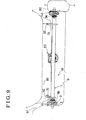
- a pair of slide rails 3 are provided, one at each of the left and right sides of the seat 95, as shown in Fig.9. They are firmly connected together by a front connecting member 6 substantially consisting of a first pipe 63 and a rear connecting member 7 substantially consisting of a second pipe 73.
- the front side of the seat 95 is secured, by attaching means, to two front arms 62 which are fixed to the first pipe 63.
- the rear side of the seat 95 is secured by attaching means to two rear arms 72 which are fixed to the second pipe 73.
- Both of the assemblies formed from a guide rail 2 and engaged slide rail 3 have a height greater than their width perpendicular to their longitudinal direction, giving both a high stiffness against load applied in the vertical direction.
- the seat slide device 10 further includes a drive device 50 for adjusting the position of the seat 95 in the longitudinal direction thereof by sliding the slide rail 3 relative to the guide rail 2.
- the drive device 50 is attached at the first pipe 63 with a bracket 63a and includes a drive source 58, whose main component is an electric motor 5 and a drive screw 55 connected to the drive source 58 with a drive cable 52.
- the drive screw 55 is rotatably supported by the slide rail 3 as described later.
- an inner vertical wall 36 of the slide rail 3 to which the front connecting member 6 and the rear connecting member 7 are attached.
- the upper and lower end portions of the inner vertical wall 36 extend horizontally inwards, thereby forming an upper hem slide flange 33 and a lower hem slide flange 35 respectively.
- the extreme inner end of the lower hem slide flange 35 further extends upwards thereby forming a U-shaped groove 35a between the lower hem side flange 35 and the inner vertical wall 36.
- the vertical length of the slide rail 3 from the bottom surface of the lower hem slide flange 35 to the top surface of the upper hem slide flange 33 is greater than the horizontal length of the slide rail 3 from the inner vertical wall 36 to the extreme end of either the lower hem slide flange 35 or the upper hem slide flange 33.
- the slide rail 3 has stiffness against load applied in the vertical direction, which is greater than the stiffness against load applied in the horizontal direction that is perpendicular to their longitudinal direction.
- the guide rail 2 to be engaged with the slide rail 3 includes an outer vertical wall 24 whose upper and lower end portions extend horizontally inwards so as to form an upper hem guide flange 21 and a lower hem guide flange 25 respectively.
- the guide rail 2 further comprises a holder flange 22 as shown in Fig. 5 which is positioned so that a small bearing track 23 is formed between the holder flange 22 and the upper hem guide flange 21.
- An opening 16 is formed at the right portion of the bearing track 23 as shown in Fig. 5 and Fig.6.
- the end portion of the lower hem guide flange 25 further extends downward to form a slide convex portion 25a.
- the vertical length of the guide rail 2 from the lower hem guide flange 25 to the upper hem guide flange 21 is greater than the horizontal length of the guide rail 2 from the outer side vertical portion 24 to the extreme end of either the lower hem guide flange 25 or the upper hem guide flange 21.
- the guide rail 2 also has stiffness against load applied in the vertical direction which is greater than the stiffness against load applied in horizontal direction perpendicular to its longitudinal direction.
- a slide shoe 48 is positioned on the upper face of the U-shaped groove 35a of the guide rail 2 such that when the slide rail 3 is engaged in the guide rail 2 the slide shoe 48 is located between the U-shaped groove 35a of the guide rail 2 and the slide convex portion 25a of the slide rail 3.
- a plurality of bearing members 46 are provided inside the bearing track 23 so as to facilitate the sliding of the slide rail 3 on the guide rail 2.
- the bearing members 46 are sandwiched in the vertical direction by the inner bottom wall of the bearing track 23 and the upper hem slide flange 33 of the slide rail 3 so as to be rolled therebetween.
- the bearing members 46 are sufficiently greased so as to produce a smooth slide operation even when a large load is applied to the seat slide device 10 through the seat 95 by the passenger. However passengers' clothes will not get soiled with this grease as the bearing members 46 are enclosed in the bearing track 23 which has only a small opening 16.
- lateral movement of the slide rail 3 relative to the guide rail 2 is limited due to the slide convex portion 25a of the guide rail 2 being engaged with the U-shaped groove 35a of the slide rail 3.
- the structure of the seat slide device 10 is such that the passenger's load and the load of the seat 95 are not applied to the slide shoe 48.
- the slide convex portion 25a of the guide rail 2 is engaged with and can slide on the slide shoe 48 smoothly without the application of any lubrication to the slide shoe 48.
- the slide shoe 48 has a plurality of protruding fixing means 48a which fit into a plurality of holes 34 formed in the slide rail 3 so as to secure said slide shoe 48 in position.
- the slide shoe 48 would be made of a steel plate in order to obtain enough abrasive endurance. In such a configuration, there is no need to apply the grease to the slide convex portion 25a of the guide rail 2.
- the plurality of bearing members 46 are divided into two groups, the two groups being separated by a separator 47 which is also housed in the bearing track 23.
- the shape of the slide rail 3 and the guide rail 2 are such that when the slide rail 3 is engaged in the guide rail 2 a space 15 is formed between their respective vertical side walls 36 and 24, below the holder flange 22 of the slide rail 3 and above the lower hem guide flange 25 of the guide rail 2.
- the drive screw 55 is provided in this space 15 in such a manner that the rotation axis of the drive screw 55 extends in the longitudinal direction of the guide rail 2 and the slide rail 3.
- the drive screw 55 is rotatably supported at each of its ends by a support plate 53 and a bearing plate 54.
- Each support plate 53 is attached to the inner vertical wall 36 of the slide rail and the rear connecting member 7 by means of a bolt 75 and nut 74.
- Each bearing plate 54 is supported in a hole 53a formed in the support plate 53 so that they are slightly movable horizontally in the direction perpendicular to the axis of the drive screw 55 (vertical direction in Fig. 4).
- a hold plate 56 made of elastic material and molded so as to be approximately U-shaped is fitted by holes 56a at each of its ends to the bearing plates 54.
- a fixing plate 57 including a projecting portion 57a which presses the hold plate 56, is attached to the support plates 53. In this manner, the driving screw 55 is engaged with and pressed into a number of a plurality of engaging holes 26 formed in the guide rail 2.
- the drive cable 52 is housed in a cable case 51.
- One end of the cable case 51 is supported by the bracket 63a which is fixed to the front connecting member 6 and supports the drive source 58.
- the other end of the cable case 51 is supported at the inner vertical wall 36 of the slide rail 3 by means of a projecting boss 51a fitting in a hole 36a formed in the inner vertical wall 36.
- the slide rail 3 is thus slide relative to the guide rail 2 in the longitudinal direction of the seat 95 by the rotation of the drive screw 55.
- a plurality of engaging holes 26 in the outer vertical wall 24 of the guide rail 2 passing therethrough and being equally spaced in the longitudinal direction of the guide rail 2.
- a slide member 41 which contains a plurality of collar portions 42 molded to be engaged with the plurality of engaging holes 26. Hooks 41a projecting in the vertical direction are provided at some of the collar portions 42. The top end of each hook 41 a is engaged with the edge of one of the plurality of engaging holes 26 so as to fix the slide member 41 to the guide rail 2.
- the plurality of engaging holes 26 are therefore covered by the plurality of collar portions 42 of the siding member 41 so that the drive screw 55 is engaged with the plurality of engaging holes 26 through the plurality of collar portions 42.
- the slide member 41 may be made of a low-friction material such as resin so as to minimize friction caused by rotation of the drive screw 55, thereby minimizing the amount of the lubricating grease that needs to be applied to the slide member 41. If the slide member 41 is made of material with a low enough coefficient of friction the lubricating grease can be entirely dispensed with. Additionally, in the above configuration, the plurality of engaging holes 26 are formed at the lower portion of the outer vertical wall 24 of the guide rail 2 so that soiling of the passenger's clothes by any applied lubricating grease or abrasive powder generated after the long-term use of the seat slide device 10 is prevented
- stoppers 81 are fixed with screws 81a to the outer vertical wall 24 of the guide rail 2 in a position adjacent to the both ends of the series of engaging holes 26.
- the stoppers 81 are penetrated through holes 82 (shown in Fig. 2) in the outer vertical wall 24 of the guide rail 2.
- the slide rail 3 is slid relative to the guide rail 2 to a predetermined front position or a predetermined rear position one of the stoppers 81 engages with the side surface of one of the support plates 53 which support the drive screw 55 thereby preventing further movement of either the slide rail 3 or drive screw 55.
- the movement of the drive screw 55 is limited by the stoppers 81 within a range from the predetermined front position to the predetermined rear position, thereby also limiting the length over which the slide rail 3 may longitudinally slide.
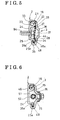
- a cover 44 for the depressed portion 27 is attached at the rear end of the guide rail 2.
- the cover 44 is fitted over a length of the guide rail 2 such that the drive screw 55 and peripheral members thereof do not interfere with the cover 44 when the slide rail 3 is moved to the backmost position of its movable range.
- the cover 44 includes concave portions at its upper and lower edge portions which fit between the holder flange 22 of the guide rail 2 and the slide rail 3 and the lower hem guide flange 25 of the guide rail 2 and the slide rail 3 respectively.
- a protruding boss 44b shown in Fig.
- the cover 44 further includes a cap portion 44a for covering the rear end portion of the guide rail 2, thereby hiding the inside of the assembly formed from the guide rail 2 and engaged slide rail 3 from the rear passenger's view.
- the seat slide device 10 which has the above configuration is mounted to the vehicle as follows.
- the guide rail 2 provided at one side of the vehicle seat 95 is fixed by attaching means to a vertical surface of a locker portion 92 of the floor 9 and the guide rail 2 provided at the other side of the vehicle seat is fixed by attaching means to the facing vertical wall of the tunnel portion 91 at the center of the vehicle, such that the two guide rails 2 are parallel with each other and the desired sliding direction of the seat 95 and are the desired width apart.
- Slide rails 3 provided at both sides of the vehicle seat are firmly connected with the front connecting member 6 and the rear connecting member 7. As shown in Figs.
- the guide rails 2 are each engaged with one of the slide rails 3 so that each individually forms an assembly whose height is greater than its width perpendicular to its longitudinal direction, thereby giving each assembly high stiffness against load applied in vertical direction.
- the seat slide device 10 also reinforces the floor 9 against excessive loads applied to the vehicle in a direction parallel to the front and rear connecting members 6 and 7 thus reducing any deformation of the vehicle shape due to such excessive loads and maintaining the passenger's space.
- the seat slide device 10 is actuated by the operation of a switch apparatus (not shown) which activates the drive member 55 and adjusts the position of the seat 95 forwards or backwards in the longitudinal direction of the vehicle.
Landscapes
- Engineering & Computer Science (AREA)
- Aviation & Aerospace Engineering (AREA)
- Transportation (AREA)
- Mechanical Engineering (AREA)
- Seats For Vehicles (AREA)
Abstract
Description
- This invention generally relates to a device for adjusting the position of a vehicle seat in the backwards and forwards direction. More particularly, the invention pertains to a seat slide device which provides enough foot space under a front vehicle seat for a rear passenger.
- A known seat slide device disclosed in US5586740B2 includes a guide rail, fixed to a vertical portion of the vehicle floor, which extends in the longitudinal direction of the vehicle seat and a slide rail, fixed to the side of the vehicle seat, which is slidably guided by said guide rail. The assembly formed by said guide rail being engaged with said slide rail has a width in the horizontal direction perpendicular to the longitudinal direction of said assembly which is substantially less than the height of said assembly in the vertical direction. Specifically; in latitudinal cross section the form of the assembly is a thin vertical bar. Thus this seat slide device can give substantial space under the vehicle seat, which may be enough, for example, for providing foot space for a rear passenger.
- According to this known seat slide device, a drive member, rotatably supported by the slide rail, is provided outside the space formed between the guide rail and the slide rail. Thus a driven engaging portion, which is to be engaged with the drive member and formed at a fixed vertical side wall of the guide rail, is exposed toward the space under the seat.
- A need therefore exists for a seat slide device which not only provides substantial foot space for a rear passenger, but also prevents any driven engaging portions from being exposed in said foot space.
- The invention provides a seat slide device having the features specified in claim 1.
- In such a configuration, the assembly comprising the guide rail and the engaged slide rail is small enough in width so as to be able to provide enough space under the seat for the feet of a rear passenger. Furthermore the drive member is completely housed in the space formed between the guide rail and the slide rail, as is the driven engaging portion which is engaged with, and slides relative to, the drive member and to which lubricating grease is applied. Thus passengers' clothes cannot be soiled by contact with lubricating grease applied to the driven engaging portion.
- The guide rail preferably includes a fixed vertical side wall and flange portions at the upper and lower extremes of said vertical side wall which extend horizontally in the same direction perpendicular to the longitudinal direction of said guide rail. The driven engaging portion is thus provided at said fixed side vertical wall. Thus soiling of passengers' clothes by contact with the driven engaging portion is further prevented.
- The seat slide device preferably further comprises a cover, which may include a cap which covers the space between the guide rail and engaged slide rail at the rear of the device, thereby giving the seat slide device a more aesthetically pleasing appearance for a rear passenger.
- The drive member is preferably engaged with the driven member through a slide member. This slide member may be made of a low friction material such as resin. Therefore the use of lubricating grease on either the drive member or the driven engaging portion can be minimized, or even dispensed with entirely.
- The drive member may be urged by a biasing member against the driven engaging portion. Thus, the seat is tightly secured in position and no lateral movement of the seat can occur.
- A plurality of bearing members, through which the guide rail is engaged with the slide rail, is preferably provided in a bearing track. Said bearing track is formed from the assembly of the guide rail and engaged slide rail while being separate from the space in said assembly which contains the drive member. Thus a sufficient amount of lubricating grease which gives a smooth slide of the seat slide device can be applied to the bearing track without soiling the drive member.
- Preferably there is a horizontal connecting member perpendicular to the slide rail. The horizontal connecting member functions as reinforcement to the vehicle and helps prevent any deformation of the vehicle caused by excessive loads applied in a direction parallel to its length.
- The foregoing and additional features and characteristics of the present invention will become more apparent from the following detailed description considered with reference to the accompanying drawings, wherein:
- Fig. 1 is a perspective view of a seat slide device according to the present invention;
- Fig. 2 is an exploded perspective view of the seat slide device of Fig. 1;
- Fig. 3 is a cross section of the seat slide device along the line A-A in Fig. 1;
- Fig. 4 is a cross section of the seat slide device along the line B-B in Fig. 1;
- Fig. 5 is a cross section of the seat slide device along the line C-C in Fig. 3;
- Fig. 6 is a cross section of the seat slide device along the line D-D in Fig. 3;
- Fig. 7 is a cross section of the seat slide device along the line E-E in Fig. 3;
- Fig. 8 is a cross section of the seat slide device along the line F-F in Fig. 3, and
- Fig. 9 is a front view of the seat slide device according to Fig. 1.
-
- An embodiment of the present invention will be explained hereinbelow referring to the attached drawings. As shown in Figs. 1, 2 and 9, a
seat slide device 10 according to the present invention includes aguide rail 2 secured to the vehicle floor 9 and aslide rail 3, engaged with theguide rail 2 so as to be slidably guided thereby, and secured to a seat 95 (shown in Fig. 9). Theslide rail 3 extends in the longitudinal direction of theseat 95. A pair ofslide rails 3 are provided, one at each of the left and right sides of theseat 95, as shown in Fig.9. They are firmly connected together by a front connecting member 6 substantially consisting of afirst pipe 63 and a rear connecting member 7 substantially consisting of asecond pipe 73. The front side of theseat 95 is secured, by attaching means, to twofront arms 62 which are fixed to thefirst pipe 63. The rear side of theseat 95 is secured by attaching means to tworear arms 72 which are fixed to thesecond pipe 73. Both of the assemblies formed from aguide rail 2 and engagedslide rail 3 have a height greater than their width perpendicular to their longitudinal direction, giving both a high stiffness against load applied in the vertical direction. - The
seat slide device 10 further includes adrive device 50 for adjusting the position of theseat 95 in the longitudinal direction thereof by sliding theslide rail 3 relative to theguide rail 2. Thedrive device 50 is attached at thefirst pipe 63 with abracket 63a and includes adrive source 58, whose main component is an electric motor 5 and adrive screw 55 connected to thedrive source 58 with adrive cable 52. Thedrive screw 55 is rotatably supported by theslide rail 3 as described later. - As shown in Figs. 5 to 8, there is formed an inner
vertical wall 36 of theslide rail 3 to which the front connecting member 6 and the rear connecting member 7 are attached. The upper and lower end portions of the innervertical wall 36 extend horizontally inwards, thereby forming an upper hem slideflange 33 and a lowerhem slide flange 35 respectively. The extreme inner end of the lowerhem slide flange 35 further extends upwards thereby forming aU-shaped groove 35a between the lowerhem side flange 35 and the innervertical wall 36. As shown in Fig. 5, the vertical length of theslide rail 3 from the bottom surface of the lowerhem slide flange 35 to the top surface of the upperhem slide flange 33 is greater than the horizontal length of theslide rail 3 from the innervertical wall 36 to the extreme end of either the lowerhem slide flange 35 or the upper hem slideflange 33. Thus theslide rail 3 has stiffness against load applied in the vertical direction, which is greater than the stiffness against load applied in the horizontal direction that is perpendicular to their longitudinal direction. - As also shown in Figs. 5 to 8 the
guide rail 2 to be engaged with theslide rail 3 includes an outervertical wall 24 whose upper and lower end portions extend horizontally inwards so as to form an upper hem guideflange 21 and a lowerhem guide flange 25 respectively. Theguide rail 2 further comprises aholder flange 22 as shown in Fig. 5 which is positioned so that asmall bearing track 23 is formed between theholder flange 22 and the upper hem guideflange 21. Anopening 16 is formed at the right portion of thebearing track 23 as shown in Fig. 5 and Fig.6. - As show in Fig. 5, the end portion of the lower
hem guide flange 25 further extends downward to form aslide convex portion 25a. The vertical length of theguide rail 2 from the lowerhem guide flange 25 to the upperhem guide flange 21 is greater than the horizontal length of theguide rail 2 from the outer sidevertical portion 24 to the extreme end of either the lower hem guideflange 25 or the upper hem guideflange 21. Thus theguide rail 2 also has stiffness against load applied in the vertical direction which is greater than the stiffness against load applied in horizontal direction perpendicular to its longitudinal direction. - A
slide shoe 48 is positioned on the upper face of the U-shapedgroove 35a of theguide rail 2 such that when theslide rail 3 is engaged in theguide rail 2 theslide shoe 48 is located between the U-shapedgroove 35a of theguide rail 2 and theslide convex portion 25a of theslide rail 3. - In addition, a plurality of bearing
members 46 are provided inside the bearingtrack 23 so as to facilitate the sliding of theslide rail 3 on theguide rail 2. In the assembledseat slide device 10 the bearingmembers 46 are sandwiched in the vertical direction by the inner bottom wall of the bearingtrack 23 and the upperhem slide flange 33 of theslide rail 3 so as to be rolled therebetween. In such a configuration, when a load is applied from theseat 95 on to theslide rail 3, the load is transmitted via the upperhem slide flange 33, to theguide rail 2 through the bearingmembers 46 and finally down to the floor 9 of the vehicle. It is preferable that the bearingmembers 46 are sufficiently greased so as to produce a smooth slide operation even when a large load is applied to theseat slide device 10 through theseat 95 by the passenger. However passengers' clothes will not get soiled with this grease as the bearingmembers 46 are enclosed in the bearingtrack 23 which has only asmall opening 16. - As shown in Fig.6 lateral movement of the
slide rail 3 relative to theguide rail 2 is limited due to the slideconvex portion 25a of theguide rail 2 being engaged with theU-shaped groove 35a of theslide rail 3. Furthermore the structure of theseat slide device 10 is such that the passenger's load and the load of theseat 95 are not applied to theslide shoe 48. Thus the slideconvex portion 25a of theguide rail 2 is engaged with and can slide on theslide shoe 48 smoothly without the application of any lubrication to theslide shoe 48. Additionally, as shown in Fig.2 and Fig.5, theslide shoe 48 has a plurality of protruding fixing means 48a which fit into a plurality ofholes 34 formed in theslide rail 3 so as to secure saidslide shoe 48 in position. If theguide rail 2 and theslide rail 3 are made of a light metal or alloy such as aluminum, theslide shoe 48 would be made of a steel plate in order to obtain enough abrasive endurance. In such a configuration, there is no need to apply the grease to the slideconvex portion 25a of theguide rail 2. - As shown in Fig. 2, the plurality of bearing
members 46 are divided into two groups, the two groups being separated by aseparator 47 which is also housed in the bearingtrack 23. - As shown in Fig.5 to Fig.8 the shape of the
slide rail 3 and theguide rail 2 are such that when theslide rail 3 is engaged in the guide rail 2 aspace 15 is formed between their respectivevertical side walls holder flange 22 of theslide rail 3 and above the lowerhem guide flange 25 of theguide rail 2. Thedrive screw 55 is provided in thisspace 15 in such a manner that the rotation axis of thedrive screw 55 extends in the longitudinal direction of theguide rail 2 and theslide rail 3. - The
drive screw 55 is rotatably supported at each of its ends by asupport plate 53 and a bearingplate 54. Eachsupport plate 53 is attached to the innervertical wall 36 of the slide rail and the rear connecting member 7 by means of abolt 75 andnut 74. Each bearingplate 54 is supported in a hole 53a formed in thesupport plate 53 so that they are slightly movable horizontally in the direction perpendicular to the axis of the drive screw 55 (vertical direction in Fig. 4). Additionally ahold plate 56 made of elastic material and molded so as to be approximately U-shaped is fitted byholes 56a at each of its ends to the bearingplates 54. A fixingplate 57, including a projectingportion 57a which presses thehold plate 56, is attached to thesupport plates 53. In this manner, the drivingscrew 55 is engaged with and pressed into a number of a plurality of engagingholes 26 formed in theguide rail 2. - There is a
non-circular hole 55b through the axis of thedrive screw 55. A matching non-circular key portion of thedrive cable 52 is inserted into thehole 55b in thedrive screw 55 so as to rotate thedrive screw 55 by actuation from thedrive source 58. As shown in Fig. 4, thedrive cable 52 is housed in acable case 51. One end of thecable case 51 is supported by thebracket 63a which is fixed to the front connecting member 6 and supports thedrive source 58. The other end of thecable case 51 is supported at the innervertical wall 36 of theslide rail 3 by means of a projectingboss 51a fitting in a hole 36a formed in the innervertical wall 36. Theslide rail 3 is thus slide relative to theguide rail 2 in the longitudinal direction of theseat 95 by the rotation of thedrive screw 55. - As shown in Fig. 4 there are formed a plurality of engaging
holes 26 in the outervertical wall 24 of theguide rail 2 passing therethrough and being equally spaced in the longitudinal direction of theguide rail 2. There is also aslide member 41 which contains a plurality ofcollar portions 42 molded to be engaged with the plurality of engagingholes 26.Hooks 41a projecting in the vertical direction are provided at some of thecollar portions 42. The top end of eachhook 41 a is engaged with the edge of one of the plurality of engagingholes 26 so as to fix theslide member 41 to theguide rail 2. The plurality of engagingholes 26 are therefore covered by the plurality ofcollar portions 42 of the sidingmember 41 so that thedrive screw 55 is engaged with the plurality of engagingholes 26 through the plurality ofcollar portions 42. Theslide member 41 may be made of a low-friction material such as resin so as to minimize friction caused by rotation of thedrive screw 55, thereby minimizing the amount of the lubricating grease that needs to be applied to theslide member 41. If theslide member 41 is made of material with a low enough coefficient of friction the lubricating grease can be entirely dispensed with. Additionally, in the above configuration, the plurality of engagingholes 26 are formed at the lower portion of the outervertical wall 24 of theguide rail 2 so that soiling of the passenger's clothes by any applied lubricating grease or abrasive powder generated after the long-term use of theseat slide device 10 is prevented - As shown in Fig. 2 and Fig. 4
stoppers 81 are fixed withscrews 81a to the outervertical wall 24 of theguide rail 2 in a position adjacent to the both ends of the series of engagingholes 26. Thestoppers 81 are penetrated through holes 82 (shown in Fig. 2) in the outervertical wall 24 of theguide rail 2. When theslide rail 3 is slid relative to theguide rail 2 to a predetermined front position or a predetermined rear position one of thestoppers 81 engages with the side surface of one of thesupport plates 53 which support thedrive screw 55 thereby preventing further movement of either theslide rail 3 or drivescrew 55. Thus the movement of thedrive screw 55 is limited by thestoppers 81 within a range from the predetermined front position to the predetermined rear position, thereby also limiting the length over which theslide rail 3 may longitudinally slide. - As shown in Fig. 2 and Fig. 5 a
cover 44 for thedepressed portion 27 is attached at the rear end of theguide rail 2. Thecover 44 is fitted over a length of theguide rail 2 such that thedrive screw 55 and peripheral members thereof do not interfere with thecover 44 when theslide rail 3 is moved to the backmost position of its movable range. As shown in Fig. 5 thecover 44 includes concave portions at its upper and lower edge portions which fit between theholder flange 22 of theguide rail 2 and theslide rail 3 and the lowerhem guide flange 25 of theguide rail 2 and theslide rail 3 respectively. Furthermore a protruding boss 44b (shown in Fig. 2) formed at the side surface of thecover 44 is engaged with ahole 29 in theguide rail 2 so as to maintain thecover 44 in a predetermined position. Thecover 44 further includes a cap portion 44a for covering the rear end portion of theguide rail 2, thereby hiding the inside of the assembly formed from theguide rail 2 and engagedslide rail 3 from the rear passenger's view. - The
seat slide device 10 according to the present invention which has the above configuration is mounted to the vehicle as follows. Theguide rail 2 provided at one side of thevehicle seat 95 is fixed by attaching means to a vertical surface of alocker portion 92 of the floor 9 and theguide rail 2 provided at the other side of the vehicle seat is fixed by attaching means to the facing vertical wall of thetunnel portion 91 at the center of the vehicle, such that the twoguide rails 2 are parallel with each other and the desired sliding direction of theseat 95 and are the desired width apart. Slide rails 3 provided at both sides of the vehicle seat are firmly connected with the front connecting member 6 and the rear connecting member 7. As shown in Figs. 5 to 8, theguide rails 2 are each engaged with one of the slide rails 3 so that each individually forms an assembly whose height is greater than its width perpendicular to its longitudinal direction, thereby giving each assembly high stiffness against load applied in vertical direction. In the above configuration theseat slide device 10 also reinforces the floor 9 against excessive loads applied to the vehicle in a direction parallel to the front and rear connecting members 6 and 7 thus reducing any deformation of the vehicle shape due to such excessive loads and maintaining the passenger's space. - The
seat slide device 10 according to the present invention is actuated by the operation of a switch apparatus (not shown) which activates thedrive member 55 and adjusts the position of theseat 95 forwards or backwards in the longitudinal direction of the vehicle.
Claims (8)
- A seat slide device (10) for a vehicle comprising:characterized in that the seat slide device (10) further comprises:a guide rail (2) which extends in the back/forth direction of the vehicle seat (95) and includes a fixed vertical side wall (24), the guide rail (2) being mountable on the vehicle floor (9); anda slide rail (3) engaged with the guide rail (2) and guided to slide in the longitudinal direction of said guide rail (2), said slide rail (3) including a vertical side wall (36) displaced from the vertical side wall of the guide rail (2) and attachable to the vehicle seat (95)a drive member (55) provided in a space (15) formed between the guide rail (2) and the slide rail (3) and rotatably supported by either one of said guide rail (2) and said slide rail (3), anda driven engaging portion (26) which is to be engaged with said drive member (55) and is formed at the other of said guide rail (2) or said slide rail (3).
- A seat slide device (10) according to Claim 1, wherein the vertical height of the assembly comprising the guide rail (2) and slide rail (3) is greater than the horizontal width as measured perpendicular to both vertical side walls.
- A seat slide device (10) according to either preceding claim, wherein the guide rail (2) includes the driven engaging portion (26) at the fixed vertical side wall (24) and flange portions (21,25) extending in the horizontal direction perpendicular to said fixed vertical side wall (24) at upper and lower portions of said fixed vertical side wall (24).
- A seat slide device (10) according to Claim 3, further comprising:a cover (44) connecting the upper and lower flange portions (21,25) of the guide rail (2) which extends along a portion of the guide rail (2) in the longitudinal direction (2) and covers some of the driven engaging portions (26).
- A seat slide device (10) according to any preceding claim, wherein the drive member (55) is engaged with the driven engaging portion (26) through a slide member (41) attached to the driven engaging portion (26).
- A seat slide device (10) according to any preceding claim, further comprising:a biasing member (56) urging the drive member (55) against the driven engaging portion (26).
- A seat slide device (10) according to any preceding claim, further comprising:a bearing track (23) provided between the guide rail (2) and the slide rail (3) separate from the space (15) provided between said guide rail (2) and said slide rail (3) in which the drive member (55) is rotatably supported, anda plurality of bearing members (46) provided in said bearing track (23) and through which the slide rail (3) is slidably supported by the guide rail (2).
- A seat slide device (10) according to any preceding claim, further comprising:a connecting member (6,7) extending in the horizontal direction perpendicular to the vertical side wall (36) of the slide rail (3) and fixed to the vertical side wall (36) of the slide rail (3), said connecting member (6,7) supporting a drive device (50) coupled to the drive member (55) through a drive cable (52).
Applications Claiming Priority (2)
| Application Number | Priority Date | Filing Date | Title |
|---|---|---|---|
| JP2003371027A JP4419518B2 (en) | 2003-10-30 | 2003-10-30 | Seat slide device |
| JP2003371027 | 2003-10-30 |
Publications (2)
| Publication Number | Publication Date |
|---|---|
| EP1527943A1 true EP1527943A1 (en) | 2005-05-04 |
| EP1527943B1 EP1527943B1 (en) | 2006-08-02 |
Family
ID=34420213
Family Applications (1)
| Application Number | Title | Priority Date | Filing Date |
|---|---|---|---|
| EP04077969A Expired - Lifetime EP1527943B1 (en) | 2003-10-30 | 2004-10-28 | Seat slide device for a vehicle |
Country Status (5)
| Country | Link |
|---|---|
| US (1) | US7104584B2 (en) |
| EP (1) | EP1527943B1 (en) |
| JP (1) | JP4419518B2 (en) |
| CN (1) | CN100497038C (en) |
| DE (1) | DE602004001735T2 (en) |
Cited By (1)
| Publication number | Priority date | Publication date | Assignee | Title |
|---|---|---|---|---|
| WO2015193096A1 (en) * | 2014-06-17 | 2015-12-23 | Rollax Gmbh & Co. Kg | Adjustment drive |
Families Citing this family (17)
| Publication number | Priority date | Publication date | Assignee | Title |
|---|---|---|---|---|
| JP2004210113A (en) * | 2002-12-27 | 2004-07-29 | T S Tec Kk | Slide rail of seat for automobile |
| FR2855797B1 (en) * | 2003-06-06 | 2005-08-19 | Inderflex Technoflex | FLEXIBLE SHAFT WITH REDUCED ELASTICITY WIRE |
| JP5266698B2 (en) * | 2007-09-21 | 2013-08-21 | アイシン精機株式会社 | Vehicle seat slide device |
| DE112009000575B4 (en) * | 2008-03-13 | 2019-02-21 | GM Global Technology Operations LLC (n. d. Ges. d. Staates Delaware) | Adjustment device for a seat |
| DE102010047043B4 (en) * | 2010-09-30 | 2021-05-06 | Adient Luxembourg Holding S.À R.L. | Longitudinal adjuster and vehicle seat |
| JP6108783B2 (en) * | 2012-01-24 | 2017-04-05 | シロキ工業株式会社 | Power seat slide device |
| JP6284856B2 (en) * | 2014-08-28 | 2018-02-28 | トヨタ紡織株式会社 | Vehicle seat slide rail |
| DE102014220049A1 (en) * | 2014-10-02 | 2016-04-07 | Schock Metallwerk Gmbh | guiding device |
| CN105966270B (en) * | 2016-05-10 | 2018-04-24 | 西华大学 | A lightweight electric vehicle axle load distribution system and its adjustment method |
| CN105774603B (en) * | 2016-05-26 | 2018-10-12 | 吉林大学 | A kind of safety chair seats of car and method with position automatic regulation function |
| JP6769309B2 (en) | 2017-01-12 | 2020-10-14 | トヨタ紡織株式会社 | Power seat power transmission |
| DE102017101996A1 (en) * | 2017-02-01 | 2018-08-02 | Ims Gear Se & Co. Kgaa | Adjustment device for adjusting a vehicle seat along a displacement axis |
| US10632865B2 (en) * | 2017-11-02 | 2020-04-28 | Ford Global Technologies, Llc | Drive cable for a seating assembly |
| EP3907104B1 (en) * | 2019-01-03 | 2025-08-20 | TS Tech Co., Ltd. | Electrically powered slide rail and vehicle seat provided with electrically powered slide rail |
| US10894488B2 (en) | 2019-05-23 | 2021-01-19 | Ford Global Technologies, Llc | Seat adjustment assembly |
| US11613213B2 (en) * | 2019-10-17 | 2023-03-28 | Brose Fahrzeugteile Gmbh & Co. Kommanditgesellschaft, Coburg | Cable driven sliding center console |
| DE102020202523A1 (en) | 2020-02-27 | 2021-09-02 | Brose Fahrzeugteile SE & Co. Kommanditgesellschaft, Coburg | Adjusting device for a vehicle seat |
Citations (4)
| Publication number | Priority date | Publication date | Assignee | Title |
|---|---|---|---|---|
| US3184209A (en) * | 1963-07-10 | 1965-05-18 | Gen Motors Corp | Horizontal drive means for powered seat adjusters |
| US5046697A (en) * | 1989-04-03 | 1991-09-10 | General Motors Corporation | Six-way adjuster apparatus and method |
| US5586740A (en) * | 1994-12-19 | 1996-12-24 | General Motors Corporation | Chuckless power seat adjuster slide |
| US20030168566A1 (en) * | 2002-02-06 | 2003-09-11 | Aisin Seiki Kabushiki Kaisha | Power sliding apparatus for a seat |
Family Cites Families (12)
| Publication number | Priority date | Publication date | Assignee | Title |
|---|---|---|---|---|
| US3313512A (en) * | 1965-09-03 | 1967-04-11 | Gen Motors Corp | Horizontal drive means for powered seat adjusters |
| US4811925A (en) * | 1986-06-23 | 1989-03-14 | Tachi-S Co. Ltd. | Slide rail |
| JP3089680B2 (en) * | 1991-03-20 | 2000-09-18 | アイシン精機株式会社 | Vehicle seat slide device |
| US5302721A (en) * | 1992-07-21 | 1994-04-12 | Hoechst-Roussel Pharmaceuticals Incorporated | Method of preparation of physostigmine carbamate derivatives from eseretholes |
| US5292164A (en) * | 1992-12-23 | 1994-03-08 | Itt Corporation | Power seat adjuster with horizontal slot drive |
| US5735500A (en) * | 1995-10-26 | 1998-04-07 | General Motors Corporation | Chuckless power seat adjuster slide |
| JP3150896B2 (en) | 1996-02-08 | 2001-03-26 | トヨタ自動車株式会社 | Vehicle seat structure |
| US5797293A (en) * | 1996-12-19 | 1998-08-25 | Lear Corporation | Plastic drive block for vehicle seat adjuster |
| US6322036B1 (en) * | 1999-10-19 | 2001-11-27 | Magna Seating Systems, Inc. | Seat track assembly having a locking mechanism with infinite engagement |
| US6352312B1 (en) * | 2000-03-24 | 2002-03-05 | Excellence Manufacturing, Inc. | Vehicle seat interlock |
| DE60316483T2 (en) * | 2002-01-23 | 2008-07-03 | Delta Kogyo Co. Ltd. | Motorically adjustable vehicle seat |
| US6762579B2 (en) * | 2002-06-03 | 2004-07-13 | Ntn Corporation | Position adjusting system for a seat of a vehicle |
-
2003
- 2003-10-30 JP JP2003371027A patent/JP4419518B2/en not_active Expired - Fee Related
-
2004
- 2004-10-14 US US10/963,577 patent/US7104584B2/en not_active Expired - Fee Related
- 2004-10-28 DE DE602004001735T patent/DE602004001735T2/en not_active Expired - Lifetime
- 2004-10-28 EP EP04077969A patent/EP1527943B1/en not_active Expired - Lifetime
- 2004-10-28 CN CNB2004100867022A patent/CN100497038C/en not_active Expired - Fee Related
Patent Citations (4)
| Publication number | Priority date | Publication date | Assignee | Title |
|---|---|---|---|---|
| US3184209A (en) * | 1963-07-10 | 1965-05-18 | Gen Motors Corp | Horizontal drive means for powered seat adjusters |
| US5046697A (en) * | 1989-04-03 | 1991-09-10 | General Motors Corporation | Six-way adjuster apparatus and method |
| US5586740A (en) * | 1994-12-19 | 1996-12-24 | General Motors Corporation | Chuckless power seat adjuster slide |
| US20030168566A1 (en) * | 2002-02-06 | 2003-09-11 | Aisin Seiki Kabushiki Kaisha | Power sliding apparatus for a seat |
Cited By (1)
| Publication number | Priority date | Publication date | Assignee | Title |
|---|---|---|---|---|
| WO2015193096A1 (en) * | 2014-06-17 | 2015-12-23 | Rollax Gmbh & Co. Kg | Adjustment drive |
Also Published As
| Publication number | Publication date |
|---|---|
| DE602004001735T2 (en) | 2007-08-02 |
| US7104584B2 (en) | 2006-09-12 |
| JP4419518B2 (en) | 2010-02-24 |
| EP1527943B1 (en) | 2006-08-02 |
| US20050093328A1 (en) | 2005-05-05 |
| DE602004001735D1 (en) | 2006-09-14 |
| CN1611383A (en) | 2005-05-04 |
| CN100497038C (en) | 2009-06-10 |
| JP2005132241A (en) | 2005-05-26 |
Similar Documents
| Publication | Publication Date | Title |
|---|---|---|
| EP1527943B1 (en) | Seat slide device for a vehicle | |
| US6655561B2 (en) | Device comprising a removable sliding central console | |
| US20130278042A1 (en) | Vehicle seat | |
| KR20160121816A (en) | Sliding armrest device for vehicle | |
| JPH0234442A (en) | Supporting structure for automobile seat sliding device | |
| US6616230B2 (en) | Slidable vehicle seat assembly | |
| JP3614098B2 (en) | Seat slide device | |
| JPH09309362A (en) | Seat sliding device | |
| US7753424B2 (en) | Armrest arrangement for a motor vehicle door | |
| US20010015401A1 (en) | Vehicle seat slide device | |
| US20200247277A1 (en) | Adjusting device for a vehicle seat | |
| JP2003039994A (en) | Sweeper mounting structure in seat slide device | |
| WO1999055546A1 (en) | Open roof construction for a vehicle | |
| JPS6343149Y2 (en) | ||
| US20020021030A1 (en) | Open roof construction for a vehicle | |
| JP5087387B2 (en) | Vehicle tonneau board device | |
| JPS59213531A (en) | Seat slide | |
| EP3383699B1 (en) | Vehicle seat | |
| US11840162B2 (en) | Vehicle seat slide attachment | |
| JP3301005B2 (en) | Bracket fixing structure for seat slide device | |
| JP2002144928A (en) | Seat slide device | |
| JP3970978B2 (en) | Seat slide lock device | |
| JPH0534434Y2 (en) | ||
| JP2024082738A (en) | Step device for vehicle | |
| JPH0513235Y2 (en) |
Legal Events
| Date | Code | Title | Description |
|---|---|---|---|
| PUAI | Public reference made under article 153(3) epc to a published international application that has entered the european phase |
Free format text: ORIGINAL CODE: 0009012 |
|
| AK | Designated contracting states |
Kind code of ref document: A1 Designated state(s): AT BE BG CH CY CZ DE DK EE ES FI FR GB GR HU IE IT LI LU MC NL PL PT RO SE SI SK TR |
|
| AX | Request for extension of the european patent |
Extension state: AL HR LT LV MK |
|
| 17P | Request for examination filed |
Effective date: 20050926 |
|
| AKX | Designation fees paid |
Designated state(s): DE FR GB TR |
|
| GRAP | Despatch of communication of intention to grant a patent |
Free format text: ORIGINAL CODE: EPIDOSNIGR1 |
|
| GRAS | Grant fee paid |
Free format text: ORIGINAL CODE: EPIDOSNIGR3 |
|
| GRAA | (expected) grant |
Free format text: ORIGINAL CODE: 0009210 |
|
| AK | Designated contracting states |
Kind code of ref document: B1 Designated state(s): DE FR GB TR |
|
| RAP1 | Party data changed (applicant data changed or rights of an application transferred) |
Owner name: AISIN SEIKI KABUSHIKI KAISHA |
|
| REG | Reference to a national code |
Ref country code: GB Ref legal event code: FG4D |
|
| REF | Corresponds to: |
Ref document number: 602004001735 Country of ref document: DE Date of ref document: 20060914 Kind code of ref document: P |
|
| ET | Fr: translation filed | ||
| PLBE | No opposition filed within time limit |
Free format text: ORIGINAL CODE: 0009261 |
|
| STAA | Information on the status of an ep patent application or granted ep patent |
Free format text: STATUS: NO OPPOSITION FILED WITHIN TIME LIMIT |
|
| 26N | No opposition filed |
Effective date: 20070503 |
|
| PGFP | Annual fee paid to national office [announced via postgrant information from national office to epo] |
Ref country code: GB Payment date: 20121024 Year of fee payment: 9 |
|
| GBPC | Gb: european patent ceased through non-payment of renewal fee |
Effective date: 20131028 |
|
| PG25 | Lapsed in a contracting state [announced via postgrant information from national office to epo] |
Ref country code: GB Free format text: LAPSE BECAUSE OF NON-PAYMENT OF DUE FEES Effective date: 20131028 |
|
| REG | Reference to a national code |
Ref country code: DE Ref legal event code: R084 Ref document number: 602004001735 Country of ref document: DE |
|
| REG | Reference to a national code |
Ref country code: DE Ref legal event code: R084 Ref document number: 602004001735 Country of ref document: DE Effective date: 20140904 |
|
| PGFP | Annual fee paid to national office [announced via postgrant information from national office to epo] |
Ref country code: TR Payment date: 20140923 Year of fee payment: 11 |
|
| REG | Reference to a national code |
Ref country code: FR Ref legal event code: PLFP Year of fee payment: 12 |
|
| PGFP | Annual fee paid to national office [announced via postgrant information from national office to epo] |
Ref country code: FR Payment date: 20150908 Year of fee payment: 12 |
|
| PGFP | Annual fee paid to national office [announced via postgrant information from national office to epo] |
Ref country code: DE Payment date: 20151020 Year of fee payment: 12 |
|
| REG | Reference to a national code |
Ref country code: DE Ref legal event code: R119 Ref document number: 602004001735 Country of ref document: DE |
|
| REG | Reference to a national code |
Ref country code: FR Ref legal event code: ST Effective date: 20170630 |
|
| PG25 | Lapsed in a contracting state [announced via postgrant information from national office to epo] |
Ref country code: DE Free format text: LAPSE BECAUSE OF NON-PAYMENT OF DUE FEES Effective date: 20170503 Ref country code: FR Free format text: LAPSE BECAUSE OF NON-PAYMENT OF DUE FEES Effective date: 20161102 |
|
| PG25 | Lapsed in a contracting state [announced via postgrant information from national office to epo] |
Ref country code: TR Free format text: LAPSE BECAUSE OF NON-PAYMENT OF DUE FEES Effective date: 20161028 |