EP1527679A2 - Futtertrog - Google Patents
Futtertrog Download PDFInfo
- Publication number
- EP1527679A2 EP1527679A2 EP04022343A EP04022343A EP1527679A2 EP 1527679 A2 EP1527679 A2 EP 1527679A2 EP 04022343 A EP04022343 A EP 04022343A EP 04022343 A EP04022343 A EP 04022343A EP 1527679 A2 EP1527679 A2 EP 1527679A2
- Authority
- EP
- European Patent Office
- Prior art keywords
- trough
- feed trough
- feed
- fitting
- groove
- Prior art date
- Legal status (The legal status is an assumption and is not a legal conclusion. Google has not performed a legal analysis and makes no representation as to the accuracy of the status listed.)
- Withdrawn
Links
Images



Classifications
-
- A—HUMAN NECESSITIES
- A01—AGRICULTURE; FORESTRY; ANIMAL HUSBANDRY; HUNTING; TRAPPING; FISHING
- A01K—ANIMAL HUSBANDRY; AVICULTURE; APICULTURE; PISCICULTURE; FISHING; REARING OR BREEDING ANIMALS, NOT OTHERWISE PROVIDED FOR; NEW BREEDS OF ANIMALS
- A01K5/00—Feeding devices for stock or game ; Feeding wagons; Feeding stacks
- A01K5/01—Feed troughs; Feed pails
Definitions
- the present invention concerns a feed trough, preferably cast in concrete, including a trough part and a foot part, the latter connected to a lower part of the trough part and having a greater cross-section than the lower part of the trough part.
- the pigs When raising pigs, it is normal today that the pigs are moved from one sty to another sty where equipment and area fit the size and age of the pigs.
- the equipment is e.g. the feed trough which is to be adapted to the size of the pigs as there is to be used greater and greater feed troughs as the animals grow and the amount of feed increases.
- Stable floors may be entirely or partially designed with slatted floor, but typically there will be a slatted floor in the area where the animals eat or stay so that excess food or droppings and water are led away from the stable, and the animals are moving around in fairly dry surroundings.
- Feed troughs that are placed on slatted floor are to be stabilised in order not to turn over and thereby to avoid wasting large parts of the feed, and/or they are to be fastened in order that the animals are not pushing around with them and possibly turn them over.
- this type of trough requires a special slatted floor in which there are regular apertures in the slats of the slatted floor simultaneously with a part of these slats are to be designed with a gripping edge for lateral attachment of the feed trough, implying increased manufacturing costs of the slatted floor.
- the grouted feed trough furthermore entails that it is impossible to rearrange the equipment in a stable area if the farmer wants a more suitable placing, e.g. by rebuilding the stable area.
- the object of the present invention is to indicate a feed trough which is easy to make and which is mobile.
- a feed trough for use in raising pigs in stables with slatted floors, but the invention may readily be applied to raising of other types of animals kept in stables with slatted floors or cages with preferably regular apertures in the bottom, e.g. for calves, horses, furred animals and the like.
- the feed trough is formed of a number of trough parts and a number of foot parts which can be assembled to a feed trough that may be secured to the slatted floor.
- Trough part and foot part are cast in one piece minimises the production process, and assembly and mounting of the feed trough is made easier.
- Trough part and foot part are connected so that the foot part is connected to the lower part of the trough part, whereby the trough part rests on the foot part.
- the foot part will have greater cross-section than the lower part of the trough part in order to ensure that the trough part stands steadily on the slatted floor without risk of overturning.
- a lower external side of the foot part is arranged to be fastened to preferably a slatted floor by means of a number of fittings. These fittings are releasably mounted to the lower external side of the foot part, e.g. with bolts, screws or the like.
- the said fitting is adapted to be secured to the foot part at an acute angle in relation to the longitudinal direction of the feed trough, preferably an angle of 45 degrees. This entails that the fitting of the feed trough will extend across one or more slats in the slatted floor so that it will be possible to secure the fitting in the part which is exposed in the apertures.
- the angle of 45 degrees with which the fitting is disposed in relation to the longitudinal direction of the feed trough, is the angle mostly used as it entails that the fitting becomes longest possible so that the fitting can extend across more slats in the slatted floor.
- an underside of the said foot part is designed with a transverse groove for receiving the fitting, entailing that the fitting can be hidden up in the underside of the foot part and that the feed trough come to support on the largest possible surface.
- Old feed remains and droppings lying in places difficult to access may rot, whereby danger of infection arises by transfer of bacteria to new feed or directly to the pigs.
- a part of the groove has greater depth in one or more sub-distances, implying that the groove, besides accommodating the fitting, may freely accommodate e.g. bolt ends or screws without their being screwed directly into the foot part of the feed trough.
- the depth of the groove may vary along the length of the sub-distance, so that by accommodating e.g. a bolt end, only a certain area of the groove will be deep enough to freely accommodate the bolt end, entailing that the feed trough by fastening can be kept in the desired place and that slackness does not occur in the fitting.
- the fitting for use in slatted floors with wide elements are provided with at least one projecting side member.
- the slats are wider than by a normal slatted floor, entailing that the pigs have greater areas in which they may walk, whereby the risk of the pigs getting sore/injured toes is significantly reduced, while at the same time the risk of their getting the toes stuck in the apertures is reduced.
- the projecting side members may imply changing the shape of the groove at the underside of the foot part since the projecting side members are to be received in the foot part in the same way as the fitting.
- a number of holes may be provided in the projecting side members, through which holes e.g. a bolt may be passed for securing the feed trough.
- These holes in the fitting and/or the projecting side members may be circular or polygonal.
- the holes are round, it will only be possible to mount the feed trough at a certain position, while by using elongated, circular or rectangular holes it will be possible to mount the feed trough in the right position and then to adjust the position of the feed trough before it is clamped.
- the fitting In order to secure the feed trough to the slatted floor, the fitting is arranged for being secured by means of T-bolts, enabling mounting the fitting on the slatted floor in the desired position and then mounting the feed trough down in the fitting and fastening it with e.g. screws into the side on a lower external side of the foot part.
- the T-bolts enable easy and rapid mounting of the fitting to the slatted floor as the at least two T-bolts of the fitting are passed down through the slats and then turned so that transverse part of the T-bolt is turned in under the slats of the slatted floor, forming a retainer against movement of the fitting.
- the T-bolts are turned again so that the transverse part of the T-bolt is released from the slats of the slatted floor, and the fitting may be taken up and moved.
- the feed trough is made up of sections of trough parts and foot parts so that it is possible with sections of e.g. 1 m to construct a feed trough extending from wall to wall in a pigsty.
- end parts of the trough part is designed with tongue and groove, providing that a tongue on a trough part may be laid in over a groove on an end-disposed trough part, whereby the feed trough can be constructed.
- the groove-and-tongue assembly of the end-disposed trough part furthermore implies guiding the two trough parts so that adaptation/mounting of a succeeding trough part can occur relatively quickly since the tongue-and-groove assembly partly ensures correct mounting.
- an underpart of the groove has less depth than the length of an end-disposed trough part, so that a top joint is formed between abutting trough parts.
- This top joint is filled with the previously mentioned elastic and acid-proof joint filler, providing that the feed trough is tight and may absorb expansion and contraction of the material due to temperature variations.
- trough parts were used with a preferably central joint groove at end parts which by assembling of two trough parts enclosed the joint filler so that it was not visible from the top side.
- trough parts are to be made with better tolerance on the plane of the end parts, as two end parts are to abut closely for forming a central joint groove in which a joint filler may be retained, which is typically a two-component joint filler having a sealing and bonding effect.
- the feed trough may be made of different types of concrete, e.g. concrete mixed with glass fibres, cellulose fibres or plastic, either for reinforcing the concrete or reducing the weight of the feed trough.
- the feed trough is cast in polymeric concrete.
- a feed trough 1 including a trough part 2 and a foot part 3 having greater cross-section than a lower part of the trough part 2.
- a fitting 4 is mounted along a lower external side 5 of the foot part 3 and in under the foot part 3 along the underside 11 and up along the opposite lower external side 5 of the foot part 3.
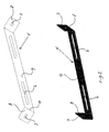
- the fitting 4 is designed with a number of holes 7 in which screws or bolts (not shown) are used for fastening the fitting 4 to the feed trough 1, while the fitting 4 is designed with a number of holes 6 in which T-bolts (not shown) are used for fastening the fitting 4 to the slatted floor (not shown).
- the fitting 4 is shown in unfolded form, where the fitting 4 includes an underlying surface 9 which is the part of the fitting 4 disposed against the underside (not shown) of the foot part (not shown), and two side members 7 which are the parts bent about folding lines 10 for being disposed against the lower external side (not shown) of the foot part (not shown).
- the holes 6, 7 are shown a circular/rectangular holes, entailing that the T-bolts (not shown) can be placed in the holes 6 opposite to an underlying slot, while bolts/screws (not shown) can be placed in the holes 7 for fastening the fitting 4 to the feed trough (not shown).
- Fig. 3 shows the underside 11 of the foot part 3 where the groove 12 is disposed at an acute angle 14, here 45 degrees, relative to the longitudinal direction of the feed trough 1.
- the groove 12 is recessed in relation to the rest of the underside 11, so that the fitting (not shown) can be received in the foot part 3 of the feed trough 1, whereby the feed trough 1 will stand on the underside 11 and not on the fittings (not shown) with which each trough part 2/foot part 3 is provided.
- the depth of the groove 12 is deeper than the surrounding part of the groove 12, entailing that bolt ends/nuts (not shown) or the like may be accommodated in the groove 12.
- Fig. 4 On Fig. 4 is shown how tongue-and-groove joint 20 forms a top joint 21 by groove 22 at end part 23 having less depth than the length of tongue 25 of juxtaposed end part 26.
- joint filler 24 is provided, ensuring that the feed trough (not shown) is tight.
- joint filler 24 is to be cut whereby end part 23 and end part 26 are released and can be removed.
Landscapes
- Life Sciences & Earth Sciences (AREA)
- Environmental Sciences (AREA)
- Birds (AREA)
- Animal Husbandry (AREA)
- Biodiversity & Conservation Biology (AREA)
- Laying Of Electric Cables Or Lines Outside (AREA)
Applications Claiming Priority (2)
| Application Number | Priority Date | Filing Date | Title |
|---|---|---|---|
| DK200301578 | 2003-10-28 | ||
| DKPA200301578 | 2003-10-28 |
Publications (2)
| Publication Number | Publication Date |
|---|---|
| EP1527679A2 true EP1527679A2 (de) | 2005-05-04 |
| EP1527679A3 EP1527679A3 (de) | 2005-10-26 |
Family
ID=34400414
Family Applications (1)
| Application Number | Title | Priority Date | Filing Date |
|---|---|---|---|
| EP04022343A Withdrawn EP1527679A3 (de) | 2003-10-28 | 2004-09-20 | Futtertrog |
Country Status (1)
| Country | Link |
|---|---|
| EP (1) | EP1527679A3 (de) |
Family Cites Families (4)
| Publication number | Priority date | Publication date | Assignee | Title |
|---|---|---|---|---|
| GB1006542A (en) * | 1961-08-19 | 1965-10-06 | Ronald William Hare | Improvements in and relating to manger curbs |
| DE3802989A1 (de) * | 1988-02-02 | 1989-08-10 | Ibo Stalltechnik Gmbh | Futtertrog |
| AT397902B (de) * | 1990-02-02 | 1994-08-25 | Braeuer Michael Ing | Futtertrog für schweine |
| GB0015911D0 (en) * | 2000-06-30 | 2000-08-23 | Carrs Agriculture Limited | Animal feed container |
-
2004
- 2004-09-20 EP EP04022343A patent/EP1527679A3/de not_active Withdrawn
Also Published As
| Publication number | Publication date |
|---|---|
| EP1527679A3 (de) | 2005-10-26 |
Similar Documents
| Publication | Publication Date | Title |
|---|---|---|
| CA1105335A (en) | Disposable pet dish | |
| CN108471718B (zh) | 畜舍,尤其用于畜养猪的畜舍 | |
| US5758598A (en) | Creep feeder device | |
| US11473314B2 (en) | Modular flooring system for agricultural animal and poultry houses | |
| US4628662A (en) | Grating for use as a floor element in a stable and grating assembly | |
| US3457901A (en) | Portable and adjustable platform extender for barns | |
| EP3326454B1 (de) | Weidestall | |
| KR102241636B1 (ko) | 가축용 급이기의 사료받침대 분뇨투입 방지장치 | |
| US3726254A (en) | Method of and housing apparatus for farrowing and finishing of farm animals | |
| US20140202390A1 (en) | Bedding For Bird Coops | |
| KR200446969Y1 (ko) | 스테인리스스틸을 이용한 양돈농장의 바닥재 | |
| EP1855519B1 (de) | Fussbodenmatte zur verwendung durch tiere | |
| RU2067821C1 (ru) | Стойло для крупного рогатого скота | |
| EP3011830A1 (de) | Vorgefertigtes modul für den boden eines viehstahls | |
| GB2366506A (en) | Anti-cast device | |
| RU2066954C1 (ru) | Площадка для содержания животных | |
| RU143900U1 (ru) | Площадка для выгула и отдыха животных | |
| WO2004002217A1 (en) | Arrangements for housing resting animals and devices for partitioning such arrangements | |
| RU93053687A (ru) | Стойло для крупного рогатого скота | |
| EP1680956B1 (de) | Futtertrog | |
| KR200407235Y1 (ko) | 애완동물용 배변기 연결구조. | |
| KR101608710B1 (ko) | 급이기의 인근에 구비되는 먹이활동 장애방지장치 | |
| EP3079462B1 (de) | Länglicher trog | |
| JP3010633U (ja) | 畜舎用床板 | |
| JPH0433741Y2 (de) |
Legal Events
| Date | Code | Title | Description |
|---|---|---|---|
| PUAI | Public reference made under article 153(3) epc to a published international application that has entered the european phase |
Free format text: ORIGINAL CODE: 0009012 |
|
| AK | Designated contracting states |
Kind code of ref document: A2 Designated state(s): AT BE BG CH CY CZ DE DK EE ES FI FR GB GR HU IE IT LI LU MC NL PL PT RO SE SI SK TR |
|
| AX | Request for extension of the european patent |
Extension state: AL HR LT LV MK |
|
| PUAL | Search report despatched |
Free format text: ORIGINAL CODE: 0009013 |
|
| AK | Designated contracting states |
Kind code of ref document: A3 Designated state(s): AT BE BG CH CY CZ DE DK EE ES FI FR GB GR HU IE IT LI LU MC NL PL PT RO SE SI SK TR |
|
| AX | Request for extension of the european patent |
Extension state: AL HR LT LV MK |
|
| 17P | Request for examination filed |
Effective date: 20060330 |
|
| AKX | Designation fees paid |
Designated state(s): AT BE BG CH CY CZ DE DK EE ES FI FR GB GR HU IE IT LI LU MC NL PL PT RO SE SI SK TR |
|
| 17Q | First examination report despatched |
Effective date: 20060803 |
|
| 17Q | First examination report despatched |
Effective date: 20060803 |
|
| STAA | Information on the status of an ep patent application or granted ep patent |
Free format text: STATUS: THE APPLICATION IS DEEMED TO BE WITHDRAWN |
|
| 18D | Application deemed to be withdrawn |
Effective date: 20091003 |