EP1527353B1 - Method for assembling a permanent magnet for a magnetic resonance imaging device - Google Patents
Method for assembling a permanent magnet for a magnetic resonance imaging device Download PDFInfo
- Publication number
- EP1527353B1 EP1527353B1 EP03734229A EP03734229A EP1527353B1 EP 1527353 B1 EP1527353 B1 EP 1527353B1 EP 03734229 A EP03734229 A EP 03734229A EP 03734229 A EP03734229 A EP 03734229A EP 1527353 B1 EP1527353 B1 EP 1527353B1
- Authority
- EP
- European Patent Office
- Prior art keywords
- magnet
- mock
- block
- blocks
- sticks
- Prior art date
- Legal status (The legal status is an assumption and is not a legal conclusion. Google has not performed a legal analysis and makes no representation as to the accuracy of the status listed.)
- Expired - Lifetime
Links
- 238000000034 method Methods 0.000 title claims abstract description 34
- 238000002595 magnetic resonance imaging Methods 0.000 title claims abstract 3
- 230000005291 magnetic effect Effects 0.000 claims abstract description 43
- 238000006073 displacement reaction Methods 0.000 claims abstract description 5
- 230000005294 ferromagnetic effect Effects 0.000 claims abstract 3
- 230000008569 process Effects 0.000 claims description 11
- 238000003780 insertion Methods 0.000 claims description 7
- 230000037431 insertion Effects 0.000 claims description 7
- 239000000696 magnetic material Substances 0.000 claims description 5
- XAGFODPZIPBFFR-UHFFFAOYSA-N aluminium Chemical compound [Al] XAGFODPZIPBFFR-UHFFFAOYSA-N 0.000 claims description 2
- 229910052782 aluminium Inorganic materials 0.000 claims description 2
- 239000006247 magnetic powder Substances 0.000 claims description 2
- 230000013011 mating Effects 0.000 claims description 2
- 229920003023 plastic Polymers 0.000 claims description 2
- 239000004033 plastic Substances 0.000 claims description 2
- 238000003825 pressing Methods 0.000 claims description 2
- 238000005245 sintering Methods 0.000 claims description 2
- 229910001220 stainless steel Inorganic materials 0.000 claims description 2
- 239000010935 stainless steel Substances 0.000 claims description 2
- 230000003068 static effect Effects 0.000 claims 1
- 239000000853 adhesive Substances 0.000 description 6
- 230000001070 adhesive effect Effects 0.000 description 6
- XEEYBQQBJWHFJM-UHFFFAOYSA-N Iron Chemical compound [Fe] XEEYBQQBJWHFJM-UHFFFAOYSA-N 0.000 description 4
- 230000003993 interaction Effects 0.000 description 2
- 239000000463 material Substances 0.000 description 2
- 229910001172 neodymium magnet Inorganic materials 0.000 description 2
- 230000001846 repelling effect Effects 0.000 description 2
- ZOXJGFHDIHLPTG-UHFFFAOYSA-N Boron Chemical compound [B] ZOXJGFHDIHLPTG-UHFFFAOYSA-N 0.000 description 1
- 229910052692 Dysprosium Inorganic materials 0.000 description 1
- 239000004593 Epoxy Substances 0.000 description 1
- 229910052796 boron Inorganic materials 0.000 description 1
- 239000010941 cobalt Substances 0.000 description 1
- 229910017052 cobalt Inorganic materials 0.000 description 1
- GUTLYIVDDKVIGB-UHFFFAOYSA-N cobalt atom Chemical compound [Co] GUTLYIVDDKVIGB-UHFFFAOYSA-N 0.000 description 1
- 150000001875 compounds Chemical class 0.000 description 1
- 230000007812 deficiency Effects 0.000 description 1
- KBQHZAAAGSGFKK-UHFFFAOYSA-N dysprosium atom Chemical compound [Dy] KBQHZAAAGSGFKK-UHFFFAOYSA-N 0.000 description 1
- 125000003700 epoxy group Chemical group 0.000 description 1
- 230000001747 exhibiting effect Effects 0.000 description 1
- 229910052742 iron Inorganic materials 0.000 description 1
- 238000004519 manufacturing process Methods 0.000 description 1
- 230000007246 mechanism Effects 0.000 description 1
- 238000012986 modification Methods 0.000 description 1
- 230000004048 modification Effects 0.000 description 1
- 229920000647 polyepoxide Polymers 0.000 description 1
- 229910052761 rare earth metal Inorganic materials 0.000 description 1
- 150000002910 rare earth metals Chemical class 0.000 description 1
- 125000006850 spacer group Chemical group 0.000 description 1
Images


Classifications
-
- G—PHYSICS
- G01—MEASURING; TESTING
- G01R—MEASURING ELECTRIC VARIABLES; MEASURING MAGNETIC VARIABLES
- G01R33/00—Arrangements or instruments for measuring magnetic variables
- G01R33/20—Arrangements or instruments for measuring magnetic variables involving magnetic resonance
- G01R33/28—Details of apparatus provided for in groups G01R33/44 - G01R33/64
- G01R33/38—Systems for generation, homogenisation or stabilisation of the main or gradient magnetic field
- G01R33/383—Systems for generation, homogenisation or stabilisation of the main or gradient magnetic field using permanent magnets
-
- Y—GENERAL TAGGING OF NEW TECHNOLOGICAL DEVELOPMENTS; GENERAL TAGGING OF CROSS-SECTIONAL TECHNOLOGIES SPANNING OVER SEVERAL SECTIONS OF THE IPC; TECHNICAL SUBJECTS COVERED BY FORMER USPC CROSS-REFERENCE ART COLLECTIONS [XRACs] AND DIGESTS
- Y10—TECHNICAL SUBJECTS COVERED BY FORMER USPC
- Y10T—TECHNICAL SUBJECTS COVERED BY FORMER US CLASSIFICATION
- Y10T29/00—Metal working
- Y10T29/49—Method of mechanical manufacture
- Y10T29/49002—Electrical device making
- Y10T29/49014—Superconductor
-
- Y—GENERAL TAGGING OF NEW TECHNOLOGICAL DEVELOPMENTS; GENERAL TAGGING OF CROSS-SECTIONAL TECHNOLOGIES SPANNING OVER SEVERAL SECTIONS OF THE IPC; TECHNICAL SUBJECTS COVERED BY FORMER USPC CROSS-REFERENCE ART COLLECTIONS [XRACs] AND DIGESTS
- Y10—TECHNICAL SUBJECTS COVERED BY FORMER USPC
- Y10T—TECHNICAL SUBJECTS COVERED BY FORMER US CLASSIFICATION
- Y10T29/00—Metal working
- Y10T29/49—Method of mechanical manufacture
- Y10T29/49002—Electrical device making
- Y10T29/4902—Electromagnet, transformer or inductor
- Y10T29/49075—Electromagnet, transformer or inductor including permanent magnet or core
- Y10T29/49078—Laminated
Definitions
- This invention relates to a method for assembling a magnetic field generator for MRI.
- a magnetic field generator for MRI uses permanent magnets.
- the magnets used in such an apparatus are often formulated from a plurality of magnet blocks. It is very difficult to place material blocks first and then magnetize each block. Therefore, in actual manufacturing, the blocks are fabricated and then magnetized. The magnetized blocks are then arranged on a plate yoke so that each of the magnet blocks has a same magnetic pole facing upward. Such arrangement on a plate yoke is difficult due to the interaction of the large magnetic forces between each of the magnet blocks.
- a surface of the plate yoke or magnet block is first applied with adhesive, and then magnet blocks are bonded or attached to the surface, as disclosed in the Japanese Patent No. 2,699,250 for example.
- a magnetic field generator incorporating the permanent magnets made of such magnet blocks is apt to produce non-uniform magnetic field between a pair of piece poles opposed to each other. Further, pole pieces for correcting the non-uniformity of the magnetic field may be tilted to produce non-uniformity in the magnetic field.
- a step of adjustment for uniformly distributing the magnetic field is indispensable.
- the magnet blocks are mounted according to the above method, the non-uniformity of the magnetic field is so large that the adjustment becomes very time consuming.
- the magnet blocks each exhibiting very large magnetic forces is placed from above, onto the upper surface of the plate yoke, making extremely difficult to fit each of the magnet blocks snugly to adjacent magnet blocks. More specifically, when mounting, each magnet block is held with a face of predetermined magnetic pole facing upward. When the magnet block is brought above the other magnet block, which is already fixed onto the plate yoke, a pulling force is generated between the two. Further, when the two magnet blocks are brought in adjacency, a repelling force is generated between the two. Since the magnet block to be placed is under such intense forces, the magnet block must be firmly held for safety while being transported. For a conventional holding mechanism, it is very difficult to fit the magnet block snugly to the place of bonding efficiently against these strong forces.
- the pair of magnet units thus assembled as above is then opposed to each other so the permanent magnets are faced at one another at a predetermined distance. This is achieved by first assembling one magnet unit, then connecting one or more posts or a column yoke to the magnet unit, and finally connecting the other magnet unit to the post(s).
- the post(s) magnetically connect the pair of magnet units, and therefore must be made of a magnetic material.
- the post is brought under the pulling force from the magnet unit. This large force makes it difficult to connect the two plate yokes with the high accuracy.
- the second magnetic unit is connected to the post already connected to the first magnet unit, it is also difficult to connect the two at a high accuracy.
- EP0978727A2 Another method to assemble a magnetic field generator is disclosed by EP0978727A2 .
- a non-magnetic fixed projection is place at the center of the yoke, with two orthogonal guide rails.
- the magnetic blocks are then slid into place and bonded to each other along the non-magnetic fixed projection and guide rails.
- This approach while adequate for its intended purposes is still cumbersome and requires additional special tooling. What is desired is a method for assembling the magnetic field generator to desired tolerances with a minimum of specialized tooling and assembly steps.
- the method may also include installing a pole piece positioning tool to facilitate location and placement of the pole piece on said magnet assembly.
- a magnetic field generator for MRI 10 comprises an upper magnet unit 11 and lower magnet unit 12.
- Each of the magnet units 11 and 12, includes, but is not limited to, a plate yoke 14.
- Each of the plate yokes 14 has a surface opposed to the other plate yoke, and this surface is provided with a permanent magnet 16, on which a pole piece 18 is provided.
- Each of the permanent magnets 16 includes a plurality of magnet blocks 20.
- Each of the magnet blocks 20 of the magnet unit 12 is fitted with adjacent ones, with a same magnetic pole facing the upward.
- each of the magnet blocks 20 of the magnet unit 11 is fitted with adjacent ones, with the other magnetic pole facing downward.
- the permanent magnet 16 of the magnet unit 12 and the permanent magnet 16 of the magnet unit 11 are faced to each other so that different magnetic poles are opposed to each other.
- the magnet blocks 20 may be a magnet made from a ternary system compound Nd-Fe-B composed mainly of neodynium (Nd), iron (Fe) and boron (B).
- Nd neodynium
- Fe iron
- B boron
- part of Nd of the Nd-Fe- B may be replaced by dysprosium (Dy) while part of the Fe may be replaced by cobalt (Co).
- the Nd-Fe-B is known as a strong neodynium magnetic material with a maximum energy product of over 320 kJ/m 3. It should be noted here that a method for making a rare earth magnet is disclosed in detail, for example, in the United States Patent No. 4,770, 723 .
- the pair of opposed magnet units 11 and 12 are supported and magnetically connected by one or more posts 22, with a selected space in between, for example 40 cm to 60 cm.
- the magnetic field generator 10 is configured to form a uniform magnetic field in a space between the pair of pole pieces 18.
- each of the magnet blocks 20 used in this embodiment includes a plurality (eight, for example) of magnet members.
- the magnet member is made by pressing and sintering magnetic powder into a general cube having the side of 4 cm to 15 cm. Then the plurality of magnet members are bonded with each other and magnetized.
- a plurality of mock-up sticks 24 are fabricated to selected lengths with non-magnetic materials such as aluminum, stainless steel and plastics.
- the size of each mock-up stick 26 of the plurality of mock-up sticks 24 is essentially the same as the real magnet blocks 20 but with slightly larger width, for example, about 0.2mm larger and of a selected length.
- Each mock-up stick may comprise one or more mock-up blocks.
- the assembly is initially "fabricated" employing the set mock-up sticks 26 laid out in parallel to populate the area for the permanent magnet 16.
- each of the mock-up sticks 26 is configured to be essentially the same cross section as a magnet block 20 with a length preferably approximately as long as a particular selected column of magnet blocks 20 on the yoke plate 14.
- a mock-up stick 26 may comprise a plurality of mock-up blocks laid out end to end to formulate a "stick".
- Employing the plurality of mock-up sticks 26, laid out in a parallel, side-by-side, sequential fashion to form a complete mock layout 30 of the permanent magnet 16 may be created as depicted in FIG. 2 .
- each mock-up stick 26 is configured to be of maximum length and therefore, the complete mock layout 30 comprises a single row of mock-up sticks 26 laid out side by side.
- FIG. 2 depicts such an exemplary configuration for the mock layout 30.
- the mock layout 30 is configured on the yoke plate 14 such that with the plurality of mock-up sticks 24 and plurality of block retainers 28 in place, a (which may include more than one) mock-up stick 26 may be removed or displaced leaving behind a slot 32 comprised on the sides of the two adjacent mock-up sticks 26 and on the bottom (or top) by the plate yoke 14.
- the block retainer 28 may include, but not be limited to, a block or clamp apparatus.
- the plurality of block retainers 28 are arranged over the perimeter of the magnet unit (11 or 12) and detachably fixed to the yoke plate 14 in a manner that facilitates assembly such as with a fastener, keeper, or adhesive.
- the end of the slot 32 may be constrained by a block retainer 28 or the block retainer may be removed to facilitate assembly.
- the remaining slot 32 may now act as a set of guides, into which, a series of magnet blocks 20 may be sequentially slid with relative ease and accuracy.
- the mock-up sticks 26 are made of non-magnetic materials, there is no magnetic interaction forces among the mock-up sticks 26 and the yoke plate 14, the pole piece 18, or other elements of the magnetic field generator 10 involved in this process.
- the assembly process is therefore relatively easy and conventional.
- the magnet blocks 20 and other components can be located as accurately as needed to maintain the desired assembly tolerances for the magnet units 11 and 12. Therefore, with removal/displacement of a first mock-up stick 26, subsequent magnet blocks 20 may be inserted specifically denoted in Figure 2 and discussed further herein.
- a pole piece positioning apparatus 50 is mounted between magnet pole pieces 18 of upper magnet unit 11 and lower magnet unit 12. The function of this apparatus is to keep pole piece 18 in accurate radial position but to allow establishing a small axial gap between pole piece 18 and mock-up sticks 26 and/or magnet blocks 20 and thereby allowing the magnet assembly process to continue without interference from the pole piece 18.
- the pole piece positioning apparatus 50 also eliminates possible movement of pole piece 18 due to magnetic forces during magnet block 20 insertions.
- a magnet block pusher is configured so that it may be aligned with each of the magnet units 11 and 12 in a manner that facilitates sliding individual magnet blocks 20 into the mock layout 30.
- the block retainers 28 are removed from the yoke plate 14 and the magnet blocks 20 are magnetized and then placed on a magnet block pusher for insertion.
- the magnet block 20 is configured to be approximately 0.2 mm smaller width than mock-up stick 26, and therefore the magnet block 20 may be readily pushed into the mock layout 30 displacing a mock-up stick 26 and following the trajectory of mock-up stick 26 into the magnet unit 11, 12.
- first magnet block 20 is pushed into mock layout 30
- second magnetized magnet block 20 is put on the magnet block pusher and pushed into mock layout 30 next to first magnet block 20.
- the size and geometry of magnet blocks 20 are configured so that the friction force between iron plate yoke 14 and other permanent magnet blocks 20 is larger than the magnetic repelling force of two magnet blocks 20 positioned next each other. Therefore, it is not necessary to apply adhesive between two magnet blocks 20 to secure them.
- Other embodiments may be employed perhaps utilizing larger tolerances in the assembly and employing adhesives or epoxies as required to retain the assembly.
- This feature of an exemplary embodiment eliminating the need for adhesives provides significant advantages in that it facilitates rework of the magnet assembly should it be necessitated. For example, should a damaged magnet block 20 require removal, because no adhesives are employed between the magnet block or the magnet blocks and the yoke plate 14, the assembly process may be essentially reversed. The damaged magnet block removed, and replaced with a new one.
- first column 34 and second column 36 are adjacent to one another such that the slot formed by the removal/displacement of the mock-up stick 26 is comprised, in this second instance, on one side by another column of at least one mock-up stick 26, on the other side by the first column 34 of magnet blocks 20 and on the bottom (or top) by the plate yoke 14.
- each of subsequent mock-up sticks 26 are replaced, forming subsequent third, fourth, and fifth columns e.g., 38, 40, and 42 respectively, of permanent magnet blocks 20.
- Figure 5 depicts a partially complete assembly of permanent magnets 20.
- each of subsequent columns of at least one mock-up stick 26 are replaced, forming the complete layout of the permanent magnet 16.
- Figure 6 depicts the complete layout and assembly of all the permanent magnet blocks 20.
- a magnetic or non-magnetic spacer/insert 44 is inserted at selected intervals with the magnet blocks 20 to ensure access for a fastener.
- certain column e.g., 34, 36 may require insertion of inserts 44, as well as combinations of various sizes of magnetic blocks to achieve the desired layout. Looking to columns 34, and 36 for example, 3 magnet blocks 20 of approximately one half the length of most other magnet blocks are employed at selected intervals to facilitate the depicted layout.
- FIG. 7 depicts the completed assembly.
Landscapes
- Physics & Mathematics (AREA)
- Condensed Matter Physics & Semiconductors (AREA)
- General Physics & Mathematics (AREA)
- Magnetic Resonance Imaging Apparatus (AREA)
Abstract
Description
- This invention relates to a method for assembling a magnetic field generator for MRI.
- A magnetic field generator for MRI uses permanent magnets. The magnets used in such an apparatus are often formulated from a plurality of magnet blocks. It is very difficult to place material blocks first and then magnetize each block. Therefore, in actual manufacturing, the blocks are fabricated and then magnetized. The magnetized blocks are then arranged on a plate yoke so that each of the magnet blocks has a same magnetic pole facing upward. Such arrangement on a plate yoke is difficult due to the interaction of the large magnetic forces between each of the magnet blocks.
- Conventionally, when placing the magnet blocks on the plate yoke, a surface of the plate yoke or magnet block is first applied with adhesive, and then magnet blocks are bonded or attached to the surface, as disclosed in the Japanese Patent No.
2,699,250 - Further, according to the above method of bonding the magnet blocks, the magnet blocks each exhibiting very large magnetic forces is placed from above, onto the upper surface of the plate yoke, making extremely difficult to fit each of the magnet blocks snugly to adjacent magnet blocks. More specifically, when mounting, each magnet block is held with a face of predetermined magnetic pole facing upward. When the magnet block is brought above the other magnet block, which is already fixed onto the plate yoke, a pulling force is generated between the two. Further, when the two magnet blocks are brought in adjacency, a repelling force is generated between the two. Since the magnet block to be placed is under such intense forces, the magnet block must be firmly held for safety while being transported. For a conventional holding mechanism, it is very difficult to fit the magnet block snugly to the place of bonding efficiently against these strong forces.
- The pair of magnet units thus assembled as above is then opposed to each other so the permanent magnets are faced at one another at a predetermined distance. This is achieved by first assembling one magnet unit, then connecting one or more posts or a column yoke to the magnet unit, and finally connecting the other magnet unit to the post(s).
- The post(s) magnetically connect the pair of magnet units, and therefore must be made of a magnetic material. Thus, when the post is connected to the magnet unit, the post is brought under the pulling force from the magnet unit. This large force makes it difficult to connect the two plate yokes with the high accuracy. Likewise, when the second magnetic unit is connected to the post already connected to the first magnet unit, it is also difficult to connect the two at a high accuracy.
- Another method to assemble a magnetic field generator is disclosed by
EP0978727A2 . In this patent, a non-magnetic fixed projection is place at the center of the yoke, with two orthogonal guide rails. The magnetic blocks are then slid into place and bonded to each other along the non-magnetic fixed projection and guide rails. This approach while adequate for its intended purposes is still cumbersome and requires additional special tooling. What is desired is a method for assembling the magnetic field generator to desired tolerances with a minimum of specialized tooling and assembly steps. - The above discussed and other drawbacks and deficiencies are overcome or alleviated by a magnetic field generator assembly method in accordance with appended claim 1.
- The method may also include installing a pole piece positioning tool to facilitate location and placement of the pole piece on said magnet assembly.
- The above discussed and other features and advantages of the present invention will be appreciated and understood by those skilled in the art from the following detailed description and drawings.
- Referring to the exemplary drawings wherein like elements are numbered alike in the several Figures:
-
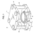
FIG. 1 depicts an cutaway view of an exemplary MRI magnetic field generator assembly; -
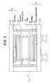
FIG. 2 depicts a graphical representation of a mock layout with exemplary mock-up sticks and insertion of a magnet block; -
FIG. 3 depicts an exemplary a pole piece positioning apparatus; -
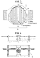
FIG. 4 depicts two views of an exemplary magnet block push tool configured with a field generator assembly; -
FIG. 5 is a graphical representation depicting further magnet block insertion on a yoke plate in an exemplary embodiment; -
FIG. 6 is a graphical representation of an exemplary process depicting a complete layout and assembly of all the permanent magnet blocks; and -
FIG. 7 depicts a completed magnet assembly. - Referring first to
Fig. 1 , a magnetic field generator forMRI 10 comprises anupper magnet unit 11 andlower magnet unit 12. Each of themagnet units plate yoke 14. Each of theplate yokes 14 has a surface opposed to the other plate yoke, and this surface is provided with apermanent magnet 16, on which apole piece 18 is provided. Each of thepermanent magnets 16 includes a plurality ofmagnet blocks 20. Each of themagnet blocks 20 of themagnet unit 12 is fitted with adjacent ones, with a same magnetic pole facing the upward. On the other hand, each of themagnet blocks 20 of themagnet unit 11 is fitted with adjacent ones, with the other magnetic pole facing downward. In other words, thepermanent magnet 16 of themagnet unit 12 and thepermanent magnet 16 of themagnet unit 11 are faced to each other so that different magnetic poles are opposed to each other. - The
magnet blocks 20 may be a magnet made from a ternary system compound Nd-Fe-B composed mainly of neodynium (Nd), iron (Fe) and boron (B). Alternatively, part of Nd of the Nd-Fe- B may be replaced by dysprosium (Dy) while part of the Fe may be replaced by cobalt (Co). The Nd-Fe-B is known as a strong neodynium magnetic material with a maximum energy product of over 320 kJ/m 3. It should be noted here that a method for making a rare earth magnet is disclosed in detail, for example, in the United States Patent No.4,770, 723 . - The pair of
opposed magnet units more posts 22, with a selected space in between, for example 40 cm to 60 cm. With such a structure, themagnetic field generator 10 is configured to form a uniform magnetic field in a space between the pair ofpole pieces 18. - Now, for the above
magnetic field generator 10, description will be made as to a method for assembling thepermanent magnet 16 by placing a plurality ofmagnet blocks 20 in a generally disc pattern on an upper surface of theplate yoke 14. Each of themagnet blocks 20 used in this embodiment includes a plurality (eight, for example) of magnet members. The magnet member is made by pressing and sintering magnetic powder into a general cube having the side of 4 cm to 15 cm. Then the plurality of magnet members are bonded with each other and magnetized. - Referring to
FIG. 2 , a plurality of mock-up sticks 24 are fabricated to selected lengths with non-magnetic materials such as aluminum, stainless steel and plastics. The size of each mock-upstick 26 of the plurality of mock-upsticks 24 is essentially the same as the real magnet blocks 20 but with slightly larger width, for example, about 0.2mm larger and of a selected length. Each mock-up stick may comprise one or more mock-up blocks. To facilitate the assembly process for thepermanent magnet 16, the assembly is initially "fabricated" employing the set mock-upsticks 26 laid out in parallel to populate the area for thepermanent magnet 16. In an exemplary embodiment, each of the mock-up sticks 26 is configured to be essentially the same cross section as amagnet block 20 with a length preferably approximately as long as a particular selected column of magnet blocks 20 on theyoke plate 14. Once again, it should be appreciated a mock-up stick 26 may comprise a plurality of mock-up blocks laid out end to end to formulate a "stick". Employing the plurality of mock-up sticks 26, laid out in a parallel, side-by-side, sequential fashion to form a completemock layout 30 of thepermanent magnet 16 may be created as depicted inFIG. 2 . In an exemplary embodiment, it will be appreciated that each mock-up stick 26 is configured to be of maximum length and therefore, the completemock layout 30 comprises a single row of mock-upsticks 26 laid out side by side.FIG. 2 depicts such an exemplary configuration for themock layout 30. - The
mock layout 30 is configured on theyoke plate 14 such that with the plurality of mock-upsticks 24 and plurality ofblock retainers 28 in place, a (which may include more than one) mock-up stick 26 may be removed or displaced leaving behind aslot 32 comprised on the sides of the two adjacent mock-upsticks 26 and on the bottom (or top) by theplate yoke 14. Theblock retainer 28 may include, but not be limited to, a block or clamp apparatus. The plurality ofblock retainers 28 are arranged over the perimeter of the magnet unit (11 or 12) and detachably fixed to theyoke plate 14 in a manner that facilitates assembly such as with a fastener, keeper, or adhesive. The end of theslot 32 may be constrained by ablock retainer 28 or the block retainer may be removed to facilitate assembly. The remainingslot 32 may now act as a set of guides, into which, a series of magnet blocks 20 may be sequentially slid with relative ease and accuracy. Advantageously, because the mock-up sticks 26 are made of non-magnetic materials, there is no magnetic interaction forces among the mock-upsticks 26 and theyoke plate 14, thepole piece 18, or other elements of themagnetic field generator 10 involved in this process. The assembly process is therefore relatively easy and conventional. The magnet blocks 20 and other components can be located as accurately as needed to maintain the desired assembly tolerances for themagnet units up stick 26, subsequent magnet blocks 20 may be inserted specifically denoted inFigure 2 and discussed further herein. - Turning now to
FIG. 3 , a polepiece positioning apparatus 50 is mounted betweenmagnet pole pieces 18 ofupper magnet unit 11 andlower magnet unit 12. The function of this apparatus is to keeppole piece 18 in accurate radial position but to allow establishing a small axial gap betweenpole piece 18 and mock-upsticks 26 and/or magnet blocks 20 and thereby allowing the magnet assembly process to continue without interference from thepole piece 18. The polepiece positioning apparatus 50 also eliminates possible movement ofpole piece 18 due to magnetic forces duringmagnet block 20 insertions. - Turning now to
FIG. 4 , a exemplary apparatus for insertion of the magnet blocks 20 is depicted. A magnet block pusher is configured so that it may be aligned with each of themagnet units mock layout 30. In an exemplary embodiment, theblock retainers 28 are removed from theyoke plate 14 and the magnet blocks 20 are magnetized and then placed on a magnet block pusher for insertion. It will be appreciated that themagnet block 20 is configured to be approximately 0.2 mm smaller width than mock-up stick 26, and therefore themagnet block 20 may be readily pushed into themock layout 30 displacing a mock-up stick 26 and following the trajectory of mock-up stick 26 into themagnet unit - After a
first magnet block 20 is pushed intomock layout 30, a secondmagnetized magnet block 20 is put on the magnet block pusher and pushed intomock layout 30 next tofirst magnet block 20. In an exemplary embodiment, the size and geometry of magnet blocks 20 are configured so that the friction force betweeniron plate yoke 14 and other permanent magnet blocks 20 is larger than the magnetic repelling force of two magnet blocks 20 positioned next each other. Therefore, it is not necessary to apply adhesive between two magnet blocks 20 to secure them. Other embodiments may be employed perhaps utilizing larger tolerances in the assembly and employing adhesives or epoxies as required to retain the assembly. - This feature of an exemplary embodiment eliminating the need for adhesives provides significant advantages in that it facilitates rework of the magnet assembly should it be necessitated. For example, should a damaged
magnet block 20 require removal, because no adhesives are employed between the magnet block or the magnet blocks and theyoke plate 14, the assembly process may be essentially reversed. The damaged magnet block removed, and replaced with a new one. - By repeating the above process, a whole column of one or more of the non-magnetic mock-up blocks 24 are replaced by column denoted by 34 of real permanent magnet blocks 20 as depicted in
FIG. 5 . After this operation is completed, the block retainers are reinstalled to secure the positions of thisparticular column 34 of permanent magnet blocks 20. Turning now to another column once again, comprising one or more mock-up sticks, anothermagnetized magnet block 20 is put on the magnet block pusher and pushed intomock layout 30, this time in another slot formed by the removal or displacement of a mock-up stick 26. Once again, by repeating the above process, a whole column comprising at least one non-magnetic mock-up stick 26 is replaced by second column denoted in this instance by 36 of real magnet blocks 20. It will be appreciated, that in an exemplary embodiment, thefirst column 34 andsecond column 36 are adjacent to one another such that the slot formed by the removal/displacement of the mock-up stick 26 is comprised, in this second instance, on one side by another column of at least one mock-up stick 26, on the other side by thefirst column 34 of magnet blocks 20 and on the bottom (or top) by theplate yoke 14. With the same process, each of subsequent mock-up sticks 26 are replaced, forming subsequent third, fourth, and fifth columns e.g., 38, 40, and 42 respectively, of permanent magnet blocks 20.Figure 5 depicts a partially complete assembly ofpermanent magnets 20. Finally, with the same process, each of subsequent columns of at least one mock-up stick 26 are replaced, forming the complete layout of thepermanent magnet 16.Figure 6 depicts the complete layout and assembly of all the permanent magnet blocks 20. - It will be appreciated, that it may be necessary to leave some locations in the
magnet 16 unoccupied bymagnet blocks 20 to provide a means for securing thepole piece 18. In an exemplary embodiment, a magnetic or non-magnetic spacer/insert 44 is inserted at selected intervals with the magnet blocks 20 to ensure access for a fastener. As is evident from observation ofFIG. 5 , certain column e.g., 34, 36 may require insertion ofinserts 44, as well as combinations of various sizes of magnetic blocks to achieve the desired layout. Looking tocolumns - Finally, to complete the magnet assembly, after all mock-up sticks 26 are replaced by magnet blocks 20 the
permanent magnet 16 is complete. The top andbottom pole pieces 18 may be engaged to the original position from polepiece positioning tool 50, mating with thepermanent magnets 16 and the task of permanent magnet assembly is completed.FIG. 7 depicts the completed assembly. - While the invention has been described with reference to a preferred embodiment, it will be understood by those skilled in the art that various changes may be made and equivalents may be substituted for elements thereof without departing from the scope of the invention. In addition, many modifications may be made to adapt a particular situation or material to the teachings of the invention without departing from the scope thereof. Therefore, it is intended that the invention not be limited to the particular embodiment disclosed as the best mode contemplated for carrying out this invention, but that the invention will include all embodiments falling within the scope of the appended claims. Moreover, the use of the terms first, second, etc. do not denote any order or importance, but rather the terms first, second, etc. are used to distinguish one element from another.
Claims (6)
- A method of assembling a magnetic field generator (10) for generating a spatially uniform main static magnetic field in a magnetic resonance imaging system, the method including assembling a magnet unit (11,12) of the magnetic field generator (10), which magnet unit (11,12) comprises- a ferromagnetic plate yoke (14),- a generally disk-shaped permanent magnet (16) provided on a surface of the plate yoke (14) and composed of a plurality of adjacent pre-magnetized magnet blocks (20),- and a pole piece (18) provided on the permanent magnet (16),
the method characterized by the steps of:a) populating the area for the permanent magnet on the surface of the ferromagnetic plate yoke (14) with a plurality of non-magnetic mock-up sticks (26), laid out in a parallel, side by side fashion to form a mock layout (30) of the permanent magnet (16), the mock-up sticks (26) being moveable relative to the surface of the plate yoke (14) and to one another;b) providing a plurality of block retainers (28) over the perimeter of the mock layout (30) at respective ends of the mock-up sticks (26), which block retainers (28) can be detachably fixed to the plate yoke (14);c) displacing or removing at least one mock-up stick (26) and installing a pre-magnetized magnet block (20) on the surface of the plate yoke (14) by pushing the magnet block (20) along the slot (32) left behind by the displacement or removal of the at least one mock-up stick (26);d) repeating said installing until a whole column (34) of adjacent magnet blocks (20) replaces said at least one displaced mock-up stick (28);e) installing block retainers (28) to secure the position of the column (34) of installed magnet blocks (20);f) repeating said steps c) - e) for other columns of the mock layout (30), each formed by at least one mock-up stick (28), until all columns of mock-up sticks are replaced by columns (34,36,38,40,42) of pre-magnetized magnet blocks (20), such that said plurality of magnet blocks (20) form a disk-shaped pattern on said surface of the plate yoke (14). - The method of claim 1, wherein the magnetic field generator (10) comprises an upper magnet unit (11) and a lower magnet unit (12) and the method further comprises:installing a pole piece positioning tool (50) between magnet pole pieces (18) of the upper magnet unit (11) and lower magnet unit (12), to keep pole pieces (18) in accurate radial position but to allow establishing a small axial gap between pole pieces (18) and mock-up sticks (26) and/or magnet blocks (20) and thereby to allow the magnet assembly process to continue without interference from the pole pieces (18), the pole piece positioning tool (50) also eliminating possible movement of pole pieces (18) due to magnetic forces during magnet block (20) insertions, andengaging the upper and lower pole pieces (18) to their original position mating with the respective permanent magnets (16) to complete the magnet assembly, after all mock-up sticks (26) are replaced by magnet blocks (20).
- The method of claim 1, wherein said installing of magnet blocks (20) includes frictionally securing said magnet blocks (20) within said mock layout (30) by frictional engagement with at least one other magnet block (20), or a block retainer (28).
- The method of claim 1, wherein each magnet block (20) includes a plurality of magnet members, and the assembling further comprises making each magnet member by pressing and sintering magnetic powder into a general cube having a side of 4 cm to 15 cm, bonding the plurality of magnet members with each other and pre-magnetizing the resulting magnet block (20).
- The method of claim 1, wherein the mock-up sticks are fabricated to selected lengths with non-magnetic materials such as aluminum, stainless steel and plastics.
- The method of claim 1, wherein the width of each mock-up stick (26) is about 0.2mm larger than that of the magnet blocks (20).
Applications Claiming Priority (3)
| Application Number | Priority Date | Filing Date | Title |
|---|---|---|---|
| US64538 | 2002-07-25 | ||
| US10/064,538 US6828891B2 (en) | 2002-07-25 | 2002-07-25 | Method for assembling magnetic members for magnetic resonance imaging magnetic field generator |
| PCT/US2003/016771 WO2004011954A1 (en) | 2002-07-25 | 2003-05-28 | Method for assembling a permanent magnet for a magnetic resonance imaging device |
Publications (2)
| Publication Number | Publication Date |
|---|---|
| EP1527353A1 EP1527353A1 (en) | 2005-05-04 |
| EP1527353B1 true EP1527353B1 (en) | 2011-03-23 |
Family
ID=30769081
Family Applications (1)
| Application Number | Title | Priority Date | Filing Date |
|---|---|---|---|
| EP03734229A Expired - Lifetime EP1527353B1 (en) | 2002-07-25 | 2003-05-28 | Method for assembling a permanent magnet for a magnetic resonance imaging device |
Country Status (7)
| Country | Link |
|---|---|
| US (1) | US6828891B2 (en) |
| EP (1) | EP1527353B1 (en) |
| JP (1) | JP4370247B2 (en) |
| KR (1) | KR101069962B1 (en) |
| CN (1) | CN100437138C (en) |
| DE (1) | DE60336476D1 (en) |
| WO (1) | WO2004011954A1 (en) |
Families Citing this family (6)
| Publication number | Priority date | Publication date | Assignee | Title |
|---|---|---|---|---|
| US7001479B2 (en) * | 2003-04-03 | 2006-02-21 | Ge Medical Systems Global Technology Company, Llc | Methods and apparatus for assembling magnetized permanent magnetic blocks |
| US6859123B2 (en) * | 2003-04-03 | 2005-02-22 | Ge Medical Systems Global Technology Company, Llc | Methods and apparatus for positioning permanent magnetic blocks |
| US7373716B2 (en) * | 2003-10-22 | 2008-05-20 | Dexter Magnetic Technologies, Inc. | Method for constructing permanent magnet assemblies |
| US20070285197A1 (en) * | 2006-06-08 | 2007-12-13 | General Electric Company | Method for disassembling a magnetic field generator |
| US8674797B2 (en) * | 2009-02-27 | 2014-03-18 | Hitachi Metals, Ltd. | Magnetic field generator |
| KR102238275B1 (en) * | 2019-11-07 | 2021-04-08 | 김명권 | magnet assembly jig |
Family Cites Families (16)
| Publication number | Priority date | Publication date | Assignee | Title |
|---|---|---|---|---|
| CA1316375C (en) | 1982-08-21 | 1993-04-20 | Masato Sagawa | Magnetic materials and permanent magnets |
| US4931760A (en) * | 1986-10-08 | 1990-06-05 | Asahi Kasei Kogyo Kabushiki Kaisha | Uniform magnetic field generator |
| GB8825529D0 (en) | 1988-11-01 | 1988-12-07 | Oxford Magnet Tech | Magnetic field generating assembly |
| US5134374A (en) * | 1989-06-01 | 1992-07-28 | Applied Superconetics | Magnetic field control apparatus |
| JPH0394733A (en) * | 1989-09-08 | 1991-04-19 | Sumitomo Special Metals Co Ltd | Magnetic field generator for mri |
| GB9105286D0 (en) | 1991-03-13 | 1991-04-24 | Oxford Instr Ltd | Magnetic field generating apparatus |
| JPH0669027A (en) | 1991-10-24 | 1994-03-11 | Hitachi Ltd | Magnetic field generator |
| DE69332601D1 (en) * | 1992-03-18 | 2003-02-06 | Sumitomo Spec Metals | MAGNETIC FIELD GENERATOR FOR IMAGE DISPLAY BY MEANS OF A CORE RESONANCE |
| JP2699250B2 (en) | 1993-01-22 | 1998-01-19 | 信越化学工業株式会社 | Magnetic field generator and method of manufacturing magnetic field generator |
| JPH0831635A (en) * | 1994-07-08 | 1996-02-02 | Sumitomo Special Metals Co Ltd | Mri magnetic field generating device |
| JP4039495B2 (en) | 1998-04-14 | 2008-01-30 | 日立金属株式会社 | Magnetic field generator for MRI |
| JP2953659B1 (en) | 1998-08-06 | 1999-09-27 | 住友特殊金属株式会社 | Magnetic field generator for MRI, method of assembling the same, and method of assembling magnet unit used therein |
| JP2000139874A (en) | 1998-09-02 | 2000-05-23 | Sumitomo Special Metals Co Ltd | Magnetic field generator for mri |
| DE60026426T2 (en) * | 1999-11-16 | 2006-11-16 | Neomax Co., Ltd. | Pole piece unit for a magnetic resonance imaging magnet |
| JP4135127B2 (en) * | 2000-04-21 | 2008-08-20 | 信越化学工業株式会社 | Assembly method of magnetic field generator |
| JP3788573B2 (en) * | 2000-11-16 | 2006-06-21 | 信越化学工業株式会社 | MRI magnetic circuit assembly method |
-
2002
- 2002-07-25 US US10/064,538 patent/US6828891B2/en not_active Expired - Fee Related
-
2003
- 2003-05-28 JP JP2004524490A patent/JP4370247B2/en not_active Expired - Fee Related
- 2003-05-28 KR KR1020047004287A patent/KR101069962B1/en not_active Expired - Fee Related
- 2003-05-28 WO PCT/US2003/016771 patent/WO2004011954A1/en not_active Ceased
- 2003-05-28 DE DE60336476T patent/DE60336476D1/en not_active Expired - Lifetime
- 2003-05-28 CN CNB038011271A patent/CN100437138C/en not_active Expired - Fee Related
- 2003-05-28 EP EP03734229A patent/EP1527353B1/en not_active Expired - Lifetime
Also Published As
| Publication number | Publication date |
|---|---|
| US20040016108A1 (en) | 2004-01-29 |
| CN100437138C (en) | 2008-11-26 |
| KR101069962B1 (en) | 2011-10-04 |
| KR20050018802A (en) | 2005-02-28 |
| DE60336476D1 (en) | 2011-05-05 |
| EP1527353A1 (en) | 2005-05-04 |
| US6828891B2 (en) | 2004-12-07 |
| JP2005533602A (en) | 2005-11-10 |
| WO2004011954A1 (en) | 2004-02-05 |
| JP4370247B2 (en) | 2009-11-25 |
| CN1556929A (en) | 2004-12-22 |
Similar Documents
| Publication | Publication Date | Title |
|---|---|---|
| EP1557684B1 (en) | Method for assembling a magnetic field generator for MRI | |
| CN205159023U (en) | Magnet unit | |
| US6664878B1 (en) | Method for assembling magnetic members for magnetic resonance imaging magnetic field generator | |
| EP0905869A3 (en) | Linear motor mechanism for exposure apparatus, and device manufacturing method using the same | |
| CN105280324B (en) | The manufacturing method of magnet unit and magnet unit | |
| EP1527353B1 (en) | Method for assembling a permanent magnet for a magnetic resonance imaging device | |
| CN101086524A (en) | Method for disassembling a magnetic field generator | |
| WO2001035427A1 (en) | Method for producing and magazining individual magnetic components and the assembly thereof for producing miniaturised magnetic systems and such magnetic systems | |
| JP2004057829A5 (en) | ||
| JP2002153438A (en) | Method of assembling magnetic circuit for MRI | |
| JP5088536B2 (en) | Assembly method of moving coil type linear motor | |
| EP1464978B1 (en) | Apparatus for assembling permanent magnets | |
| JP2006020379A (en) | Rotor manufacturing method and apparatus | |
| JP4190025B2 (en) | MRI magnetic circuit assembly method | |
| JPH08275420A (en) | Magnetic circuit and method for assembling magnetic pole magnets thereof | |
| JPH0262010A (en) | Manufacture of magnetic circuit and jig therefor | |
| JP2003086609A (en) | Electronic component assembly equipment | |
| JP2001110598A (en) | Insert light source | |
| JPS62152350A (en) | How to assemble electromagnetic equipment |
Legal Events
| Date | Code | Title | Description |
|---|---|---|---|
| PUAI | Public reference made under article 153(3) epc to a published international application that has entered the european phase |
Free format text: ORIGINAL CODE: 0009012 |
|
| 17P | Request for examination filed |
Effective date: 20050225 |
|
| AK | Designated contracting states |
Kind code of ref document: A1 Designated state(s): AT BE BG CH CY CZ DE DK EE ES FI FR GB GR HU IE IT LI LU MC NL PT RO SE SI SK TR |
|
| RBV | Designated contracting states (corrected) |
Designated state(s): DE GB NL |
|
| 17Q | First examination report despatched |
Effective date: 20100323 |
|
| GRAP | Despatch of communication of intention to grant a patent |
Free format text: ORIGINAL CODE: EPIDOSNIGR1 |
|
| GRAS | Grant fee paid |
Free format text: ORIGINAL CODE: EPIDOSNIGR3 |
|
| GRAA | (expected) grant |
Free format text: ORIGINAL CODE: 0009210 |
|
| AK | Designated contracting states |
Kind code of ref document: B1 Designated state(s): DE GB NL |
|
| REG | Reference to a national code |
Ref country code: GB Ref legal event code: FG4D |
|
| REF | Corresponds to: |
Ref document number: 60336476 Country of ref document: DE Date of ref document: 20110505 Kind code of ref document: P |
|
| REG | Reference to a national code |
Ref country code: DE Ref legal event code: R096 Ref document number: 60336476 Country of ref document: DE Effective date: 20110505 |
|
| REG | Reference to a national code |
Ref country code: NL Ref legal event code: T3 |
|
| PGFP | Annual fee paid to national office [announced via postgrant information from national office to epo] |
Ref country code: NL Payment date: 20110531 Year of fee payment: 9 Ref country code: GB Payment date: 20110525 Year of fee payment: 9 |
|
| PGFP | Annual fee paid to national office [announced via postgrant information from national office to epo] |
Ref country code: DE Payment date: 20110418 Year of fee payment: 9 |
|
| PLBE | No opposition filed within time limit |
Free format text: ORIGINAL CODE: 0009261 |
|
| STAA | Information on the status of an ep patent application or granted ep patent |
Free format text: STATUS: NO OPPOSITION FILED WITHIN TIME LIMIT |
|
| 26N | No opposition filed |
Effective date: 20111227 |
|
| REG | Reference to a national code |
Ref country code: DE Ref legal event code: R097 Ref document number: 60336476 Country of ref document: DE Effective date: 20111227 |
|
| REG | Reference to a national code |
Ref country code: NL Ref legal event code: V1 Effective date: 20121201 |
|
| GBPC | Gb: european patent ceased through non-payment of renewal fee |
Effective date: 20120528 |
|
| REG | Reference to a national code |
Ref country code: DE Ref legal event code: R119 Ref document number: 60336476 Country of ref document: DE Effective date: 20121201 |
|
| PG25 | Lapsed in a contracting state [announced via postgrant information from national office to epo] |
Ref country code: NL Free format text: LAPSE BECAUSE OF NON-PAYMENT OF DUE FEES Effective date: 20121201 |
|
| PG25 | Lapsed in a contracting state [announced via postgrant information from national office to epo] |
Ref country code: GB Free format text: LAPSE BECAUSE OF NON-PAYMENT OF DUE FEES Effective date: 20120528 |
|
| PG25 | Lapsed in a contracting state [announced via postgrant information from national office to epo] |
Ref country code: DE Free format text: LAPSE BECAUSE OF NON-PAYMENT OF DUE FEES Effective date: 20121201 |