EP1527247B1 - Door actuator - Google Patents
Door actuator Download PDFInfo
- Publication number
- EP1527247B1 EP1527247B1 EP20030766275 EP03766275A EP1527247B1 EP 1527247 B1 EP1527247 B1 EP 1527247B1 EP 20030766275 EP20030766275 EP 20030766275 EP 03766275 A EP03766275 A EP 03766275A EP 1527247 B1 EP1527247 B1 EP 1527247B1
- Authority
- EP
- European Patent Office
- Prior art keywords
- door
- brake
- coupling
- similar
- spindle
- Prior art date
- Legal status (The legal status is an assumption and is not a legal conclusion. Google has not performed a legal analysis and makes no representation as to the accuracy of the status listed.)
- Expired - Lifetime
Links
- 230000008878 coupling Effects 0.000 claims 10
- 238000010168 coupling process Methods 0.000 claims 10
- 238000005859 coupling reaction Methods 0.000 claims 10
- 239000003302 ferromagnetic material Substances 0.000 claims 2
- 238000009423 ventilation Methods 0.000 description 8
- 239000003990 capacitor Substances 0.000 description 3
- 230000004913 activation Effects 0.000 description 2
- 238000006073 displacement reaction Methods 0.000 description 2
- 238000004140 cleaning Methods 0.000 description 1
- 230000009194 climbing Effects 0.000 description 1
- 238000010276 construction Methods 0.000 description 1
- 230000005611 electricity Effects 0.000 description 1
- 230000002349 favourable effect Effects 0.000 description 1
- 238000007689 inspection Methods 0.000 description 1
- 239000012086 standard solution Substances 0.000 description 1
- 230000008646 thermal stress Effects 0.000 description 1
Images

Classifications
-
- E—FIXED CONSTRUCTIONS
- E05—LOCKS; KEYS; WINDOW OR DOOR FITTINGS; SAFES
- E05F—DEVICES FOR MOVING WINGS INTO OPEN OR CLOSED POSITION; CHECKS FOR WINGS; WING FITTINGS NOT OTHERWISE PROVIDED FOR, CONCERNED WITH THE FUNCTIONING OF THE WING
- E05F15/00—Power-operated mechanisms for wings
- E05F15/60—Power-operated mechanisms for wings using electrical actuators
- E05F15/603—Power-operated mechanisms for wings using electrical actuators using rotary electromotors
- E05F15/632—Power-operated mechanisms for wings using electrical actuators using rotary electromotors for horizontally-sliding wings
- E05F15/652—Power-operated mechanisms for wings using electrical actuators using rotary electromotors for horizontally-sliding wings operated by screw-and-nut mechanisms
-
- E—FIXED CONSTRUCTIONS
- E05—LOCKS; KEYS; WINDOW OR DOOR FITTINGS; SAFES
- E05F—DEVICES FOR MOVING WINGS INTO OPEN OR CLOSED POSITION; CHECKS FOR WINGS; WING FITTINGS NOT OTHERWISE PROVIDED FOR, CONCERNED WITH THE FUNCTIONING OF THE WING
- E05F15/00—Power-operated mechanisms for wings
- E05F15/60—Power-operated mechanisms for wings using electrical actuators
- E05F15/603—Power-operated mechanisms for wings using electrical actuators using rotary electromotors
- E05F15/632—Power-operated mechanisms for wings using electrical actuators using rotary electromotors for horizontally-sliding wings
- E05F15/655—Power-operated mechanisms for wings using electrical actuators using rotary electromotors for horizontally-sliding wings specially adapted for vehicle wings
-
- E—FIXED CONSTRUCTIONS
- E05—LOCKS; KEYS; WINDOW OR DOOR FITTINGS; SAFES
- E05Y—INDEXING SCHEME RELATING TO HINGES OR OTHER SUSPENSION DEVICES FOR DOORS, WINDOWS OR WINGS AND DEVICES FOR MOVING WINGS INTO OPEN OR CLOSED POSITION, CHECKS FOR WINGS AND WING FITTINGS NOT OTHERWISE PROVIDED FOR, CONCERNED WITH THE FUNCTIONING OF THE WING
- E05Y2201/00—Constructional elements; Accessories therefore
- E05Y2201/20—Brakes; Disengaging means, e.g. clutches; Holders, e.g. locks; Stops; Accessories therefore
- E05Y2201/214—Disengaging means
- E05Y2201/216—Clutches
-
- E—FIXED CONSTRUCTIONS
- E05—LOCKS; KEYS; WINDOW OR DOOR FITTINGS; SAFES
- E05Y—INDEXING SCHEME RELATING TO HINGES OR OTHER SUSPENSION DEVICES FOR DOORS, WINDOWS OR WINGS AND DEVICES FOR MOVING WINGS INTO OPEN OR CLOSED POSITION, CHECKS FOR WINGS AND WING FITTINGS NOT OTHERWISE PROVIDED FOR, CONCERNED WITH THE FUNCTIONING OF THE WING
- E05Y2201/00—Constructional elements; Accessories therefore
- E05Y2201/20—Brakes; Disengaging means, e.g. clutches; Holders, e.g. locks; Stops; Accessories therefore
- E05Y2201/218—Holders
- E05Y2201/22—Locks
-
- E—FIXED CONSTRUCTIONS
- E05—LOCKS; KEYS; WINDOW OR DOOR FITTINGS; SAFES
- E05Y—INDEXING SCHEME RELATING TO HINGES OR OTHER SUSPENSION DEVICES FOR DOORS, WINDOWS OR WINGS AND DEVICES FOR MOVING WINGS INTO OPEN OR CLOSED POSITION, CHECKS FOR WINGS AND WING FITTINGS NOT OTHERWISE PROVIDED FOR, CONCERNED WITH THE FUNCTIONING OF THE WING
- E05Y2201/00—Constructional elements; Accessories therefore
- E05Y2201/20—Brakes; Disengaging means, e.g. clutches; Holders, e.g. locks; Stops; Accessories therefore
- E05Y2201/23—Actuation thereof
- E05Y2201/232—Actuation thereof by automatically acting means
- E05Y2201/234—Actuation thereof by automatically acting means direction dependent
-
- E—FIXED CONSTRUCTIONS
- E05—LOCKS; KEYS; WINDOW OR DOOR FITTINGS; SAFES
- E05Y—INDEXING SCHEME RELATING TO HINGES OR OTHER SUSPENSION DEVICES FOR DOORS, WINDOWS OR WINGS AND DEVICES FOR MOVING WINGS INTO OPEN OR CLOSED POSITION, CHECKS FOR WINGS AND WING FITTINGS NOT OTHERWISE PROVIDED FOR, CONCERNED WITH THE FUNCTIONING OF THE WING
- E05Y2201/00—Constructional elements; Accessories therefore
- E05Y2201/20—Brakes; Disengaging means, e.g. clutches; Holders, e.g. locks; Stops; Accessories therefore
- E05Y2201/23—Actuation thereof
- E05Y2201/246—Actuation thereof by motors, magnets, springs or weights
-
- E—FIXED CONSTRUCTIONS
- E05—LOCKS; KEYS; WINDOW OR DOOR FITTINGS; SAFES
- E05Y—INDEXING SCHEME RELATING TO HINGES OR OTHER SUSPENSION DEVICES FOR DOORS, WINDOWS OR WINGS AND DEVICES FOR MOVING WINGS INTO OPEN OR CLOSED POSITION, CHECKS FOR WINGS AND WING FITTINGS NOT OTHERWISE PROVIDED FOR, CONCERNED WITH THE FUNCTIONING OF THE WING
- E05Y2201/00—Constructional elements; Accessories therefore
- E05Y2201/40—Motors; Magnets; Springs; Weights; Accessories therefore
- E05Y2201/43—Motors
- E05Y2201/434—Electromotors; Details thereof
-
- E—FIXED CONSTRUCTIONS
- E05—LOCKS; KEYS; WINDOW OR DOOR FITTINGS; SAFES
- E05Y—INDEXING SCHEME RELATING TO HINGES OR OTHER SUSPENSION DEVICES FOR DOORS, WINDOWS OR WINGS AND DEVICES FOR MOVING WINGS INTO OPEN OR CLOSED POSITION, CHECKS FOR WINGS AND WING FITTINGS NOT OTHERWISE PROVIDED FOR, CONCERNED WITH THE FUNCTIONING OF THE WING
- E05Y2201/00—Constructional elements; Accessories therefore
- E05Y2201/60—Suspension or transmission members; Accessories therefore
- E05Y2201/622—Suspension or transmission members elements
- E05Y2201/696—Screw mechanisms
- E05Y2201/702—Spindles; Worms
-
- E05Y2400/3014—
-
- E—FIXED CONSTRUCTIONS
- E05—LOCKS; KEYS; WINDOW OR DOOR FITTINGS; SAFES
- E05Y—INDEXING SCHEME RELATING TO HINGES OR OTHER SUSPENSION DEVICES FOR DOORS, WINDOWS OR WINGS AND DEVICES FOR MOVING WINGS INTO OPEN OR CLOSED POSITION, CHECKS FOR WINGS AND WING FITTINGS NOT OTHERWISE PROVIDED FOR, CONCERNED WITH THE FUNCTIONING OF THE WING
- E05Y2800/00—Details, accessories and auxiliary operations not otherwise provided for
- E05Y2800/25—Emergency conditions
-
- E—FIXED CONSTRUCTIONS
- E05—LOCKS; KEYS; WINDOW OR DOOR FITTINGS; SAFES
- E05Y—INDEXING SCHEME RELATING TO HINGES OR OTHER SUSPENSION DEVICES FOR DOORS, WINDOWS OR WINGS AND DEVICES FOR MOVING WINGS INTO OPEN OR CLOSED POSITION, CHECKS FOR WINGS AND WING FITTINGS NOT OTHERWISE PROVIDED FOR, CONCERNED WITH THE FUNCTIONING OF THE WING
- E05Y2900/00—Application of doors, windows, wings or fittings thereof
- E05Y2900/50—Application of doors, windows, wings or fittings thereof for vehicles
- E05Y2900/51—Application of doors, windows, wings or fittings thereof for vehicles for railway cars or mass transit vehicles
-
- Y—GENERAL TAGGING OF NEW TECHNOLOGICAL DEVELOPMENTS; GENERAL TAGGING OF CROSS-SECTIONAL TECHNOLOGIES SPANNING OVER SEVERAL SECTIONS OF THE IPC; TECHNICAL SUBJECTS COVERED BY FORMER USPC CROSS-REFERENCE ART COLLECTIONS [XRACs] AND DIGESTS
- Y10—TECHNICAL SUBJECTS COVERED BY FORMER USPC
- Y10T—TECHNICAL SUBJECTS COVERED BY FORMER US CLASSIFICATION
- Y10T70/00—Locks
- Y10T70/70—Operating mechanism
Definitions
- the invention relates to a door operator, in particular the door lock, of rail vehicles, comprising a spindle drive whose spindle is connected to a freewheel, which allows the rotation of the spindle in the direction corresponding to the closing direction of the door, and the rotation of the spindle in the direction , which corresponds to the opening direction, prevents the spindle-distal part of the freewheel rotatably, but by a ventilated by a solenoid clutch, brake or the like. is mounted releasably fixed relative to a ventilation device against the force of at least one Anpreßfeder and the brake, clutch or the like. fixed or fixable in its open position
- Such a door drive according to the preamble of claim 1 is known from US 3,745,705 A known. It describes a pivoting sliding door, which is driven by a spindle which moves a door leaf via a nut.
- a freewheel connected to the spindle permits movement of the door leaf in the closing direction, but prevents movement in the opening direction.
- a gear connected to the freewheel can be locked via a latchable in the recesses of the gear pawl. This is done in the closed position of the door.
- the pawl is brought by means of a magnet in a gear-releasing position, whereby the freewheel in its entirety is rotatable about the spindle axis.
- the pawl By means of a retaining bolt, the pawl is fixed in the gear releasing position, whereby a power-off of the magnet during the opening and closing of the door is possible.
- the pawl remains in the released position during the entire opening and closing operation of the door. Only just before the door edges when closing abut each other or on a door frame, the retaining latch is moved by a pin moved with the door leaf, whereby the pawl engages in the gear. Due to the freewheel is now possible despite locked gear, the achievement of an optimal tightness with tension end position.
- the GB 2 283 054 A and the WO 95/09959 describe a pivoting sliding door, which is driven by a spindle, which moves the door via a nut.
- the drive end remote from the spindle is connected via a freewheel with a receptacle.
- the freewheel allows the rotation of the spindle in the direction corresponding to the closing movement of the door, even with recorded recording.
- This is optionally rotatably or rotatably mounted under the action of a brake or clutch.
- the receptacle is connected via a shaft with a clutch disc.
- a rod acts on two, relative to the car body non-rotatable and with respect to the shaft axially displaceable counter discs.
- the clutch disc and thus the receptacle is released, whereby an opening of the door is made possible.
- This release takes place in normal operation by an electromagnet or in an emergency by means of a Bowden cable.
- the brake or clutch remains released as long as the solenoid is energized. In an interruption of the current, the brake or clutch is brought by means of springs in the unventilated position.
- a spindle drive To allow at any time to close the door, even a manual closing, a freewheel is arranged at one end of the spindle, which allows the rotation of the spindle in the direction corresponding to the closing movement of the door, a rotation of the spindle in the direction of the Opening movement corresponds but prevented.
- the spindelfeme part of the freewheel is rotatably mounted with respect to the car body and fixed in general by a brake, clutch or the like. If it comes in the course of normal operation to open the door, so this brake, clutch or the like.
- the invention thus has the object to provide a device with which in a door drive of the type mentioned the problems mentioned do not occur and it is particularly possible to find with smaller solenoids Ausmaschine and with the energy stored in the conventional capacitors the door several times to open.
- a preferred embodiment of the invention is characterized in that the closing magnet and the lifting magnet are designed in the form of a double-acting magnet. Simple, small, double-acting magnets can be used.
- the fixation is carried out by a linkage for the movement of the brake or clutch od.dergl., Which is guided in the course of the ventilation movement over a dead center.
- the brake or clutch remains in the open position despite the pressing spring, even when the solenoid is de-energized.
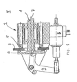
- FIG. 1 A spindle 1 of the door drive, with the (not shown) tfemen end of the freewheel, the brake or the like.
- the ventilation device 2 consists in the illustrated embodiment of a toothed disc 3, which is non-rotatably, but axially displaceable relative to the car body 4 is arranged and by means of Anpreßfedem 5 in the direction of the axis 7 of Spindle 1 is pressed against the spindle toothed disk 6.
- a lifting magnet 8 in the ventilation device 2 which, by means of a mechanism generally referred to as linkage or lever 9, the rotationally fixed toothed disc 3 axially against the force of the pressure springs 5 moved away from the spindle toothed disk 6 so far that, as in Fig. 1 shown, the ridges of the teeth low air in the axial direction to each other have, so that the spindle disc 6 can rotate in the direction which is blocked by the (not shown) freewheel.
- the remote parts of the freewheel rotate with it, so that the entire freewheel rotates with the spindle 1.
- the linkage or the lever 9 in such a way that it is in the position in which it rotates the non-rotatable toothed disc 3 sufficient, even if the solenoid 8 is de-energized
- the lever 9 passes in the course of the ventilation movement over a so-called dead center and in the end position beyond the dead center, as it is in Fig. 1 is shown, the gears are in the disengaged position.
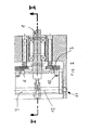
- the entire mechanism of the lever 9 is from the Fig. 2 clearly recognizable, it consists of the angled, possibly multi-part lever 9, the hinge is pivotally mounted in the ventilation device 2 in a bearing 11, and by means of rollers 10 on the periphery of the rotationally fixed, but axially movable toothed disc 3 acts.
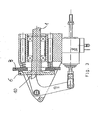
- the rollers describe around the axis of the bearing 11 a circular arc, where, as from the cohesion between Fig. 1 and Fig. 3 appears in the in Fig. 3 shown locked position, the teeth of the rotationally fixed toothed disc 3 and the spindle toothed disc 6 are engaged, while in the in Fig. 1 shown location of these gears spaced from each other, are just aired.
- the dead center mechanism is based in the illustrated embodiment on the arrangement of the two end positions of the linkage 9, as in Fig. 1 respectively.
- Fig. 3 The roller 10, actually its axis of rotation, takes between the two end positions once a position in which the connecting plane between the bearing axis 12 and the axis of rotation parallel to the direction of displacement of the Sprocket 3 (in the direction of the spring force) runs. This position corresponds to the dead center, since on both sides by the angular position of the connection plane relative to the displacement direction, a component of the spring force acts away from the dead center on the linkage.
- the variant shown in the drawing is not only robust, but allows easy adjustment and by the appropriate choice of the length of the lever arms of the lever 9 a favorable translation, so even with an extremely small and little power receiving lifting 8 a large force of the pressure springs 5 can be overcome, as in a comparison between the Fig. 1 and 3 is easily apparent.
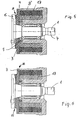
- FIGS. 5 and 6 show the variant of the invention with at least one, preferably a plurality of evenly arranged along the periphery of a circle in the housing permanent magnet 13th
- the Fig. 5 shows the locked position in which there is an air gap H between the housing and the toothed disc 3, which meshes with the spindle gear 6 against the car body 4 non-rotatable toothed disc 3 and thus prevents the rotation of the spindle 1 in the opening direction.
- the Fig. 6 shows the released position in which the teeth are disengaged, as the tooth gap 15 between the two tooth areas, the air gap H, however, is closed, the toothed disc 3 is in the contact area 16 on the housing or has a minimum, barely representable distance, as the toothed disc 3 rests on the permanent magnet 13 and is to be regarded as a kind of yoke.
- the holding force of the permanent magnets 13 is greater than the force of the pressure springs 5, so that even when switched off solenoid 8 'the brake, clutch, od.dergl. remains stable ventilated.
- the lifting magnet 8 ' are energized in the opposite direction, the combined force of the lifting magnet and the pressure springs overcomes the attraction of the permanent magnet and the position according to Fig. 5 will be achieved again.
- the force of the pressure springs 5 linear force drop with increasing distance
- the attraction force of the permanent magnets square force drop with increasing distance
- the toothing between the fixed toothed disc 3 and the spindle toothed disc 6 may be formed symmetrically or asymmetrically and in the latter case, especially in one direction, according to the closing direction of the door, be formed so flat that it represents an additional freewheel, ie that od in an emergency .dgl. from the user of the door with predetermined force against the pressure springs 5, the two discs 3, 6 tooth by tooth against each other are rotatable.
- asymmetric tooth flanks make it possible to drive the torque required for climbing over in the opening direction to any desired level, with the mechanical stability and, if appropriate, a desired possibility for overcrowding, being a practical limit.
Landscapes
- Power-Operated Mechanisms For Wings (AREA)
- Braking Arrangements (AREA)
- Lock And Its Accessories (AREA)
Description
Die Erfindung betrifft einen Türantrieb, insbesondere die Türverriegelung, von Schienenfahrzeugen, aufweisend einen Spindelantrieb, dessen Spindel mit einem Freilauf verbunden ist, der die Drehung der Spindel in der Richtung, die der Schließrichtung der Tür entspricht, gestattet und die Drehung der Spindel in der Richtung, die der Öffnungsrichtung entspricht, verhindert, wobei der spindelferne Teil des Freilaufs drehbar, aber durch eine von einem Hubmagneten lüftbare Kupplung, Bremse od.dgl. gegen die Kraft zumindest einer Anpreßfeder lösbar fixiert bezüglich einer Lüftungsvorrichtung gelagert ist und die Bremse, Kupplung od.dgl. in ihrer Offenposition fixiert oder fixierbar istThe invention relates to a door operator, in particular the door lock, of rail vehicles, comprising a spindle drive whose spindle is connected to a freewheel, which allows the rotation of the spindle in the direction corresponding to the closing direction of the door, and the rotation of the spindle in the direction , which corresponds to the opening direction, prevents the spindle-distal part of the freewheel rotatably, but by a ventilated by a solenoid clutch, brake or the like. is mounted releasably fixed relative to a ventilation device against the force of at least one Anpreßfeder and the brake, clutch or the like. fixed or fixable in its open position
Ein derartiger Türantrieb gemäß dem Oberbegriff von Anspruch 1 ist aus der
Die
Zahlreiche Schienenfahrzeuge weisen Türantriebe auf, die über einen Spindelantrieb verfügen. Um jederzeit ein Schließen der Türe zu ermöglichen, auch ein händisches Schließen, ist an einem Ende der Spindel ein Freilauf angeordnet, der das Drehen der Spindel in der Richtung die der Schließbewegung der Türe entspricht, gestattet, ein Drehen der Spindel in der Richtung die der Öffnungsbewegung entspricht aber verhindert. Um nun die Türe dennoch öffnen zu können, ist der spindelfeme Teil des Freilaufes drehbar bezüglich des Wagenkastens montiert und im allgemeinen durch eine Bremse, Kupplung oder dergleichen fixiert. Wenn es nun im Zuge des normalen Betriebs zum Öffnen der Türe kommt, so wird diese Bremse, Kupplung od.dgl. durch einen Hubmagneten gelüftet, so daß der Türantrieb die Spindel in der Richtung die der Öffnungsbewegung der Tür entspricht, verdrehen kann, wobei er naturgemäß den gesamten Freilauf mitnimmt. Kommt es in Not-oder Gefahrensituationen zum händischen Öffnen, so kann diese Bremse, Kupplung od.dgl. durch den Tümotgriff gelüftet werden und die Türe kann händisch geöffnet werden.Numerous rail vehicles have door drives that have a spindle drive. To allow at any time to close the door, even a manual closing, a freewheel is arranged at one end of the spindle, which allows the rotation of the spindle in the direction corresponding to the closing movement of the door, a rotation of the spindle in the direction of the Opening movement corresponds but prevented. In order to still be able to open the door, the spindelfeme part of the freewheel is rotatably mounted with respect to the car body and fixed in general by a brake, clutch or the like. If it comes in the course of normal operation to open the door, so this brake, clutch or the like. released by a solenoid, so that the door drive can rotate the spindle in the direction corresponding to the opening movement of the door, whereby it naturally entrains the entire freewheel. If it comes in emergency or dangerous situations for manual opening, so this brake, clutch or the like. be vented through the Tümotgriff and the door can be opened by hand.
Diese Türen haben sich in Betrieb hervorragend bewährt und stellen insbesondere wegen ihres kompakten Aufbaues, ihrer robusten Bauweise und ihrer Betriebssicherheit eine weit verbreitete Standardlösung für die Türen von Schienenfahrzeugen dar.These doors have proven themselves in operation excellent and represent a widespread standard solution for the doors of rail vehicles, in particular because of their compact design, their robust construction and their reliability.
Einen gewissen Nachteil derartiger Türen stellt der Hubmagnet dar, der bei jeder Öffnungsbewegung der Türe über die gesamte Öffnungszeit aktiviert werden muß und der daher auf längere Betriebsdauem ausgelegt werden muß. Da er auch beträchtliche Kräfte überwinden muß, ist es notwendig, einen entsprechend kräftigen und daher großen, teuren, strombedürftigen Hubmagneten vorzusehen.A certain disadvantage of such doors is the solenoid, which must be activated during each opening movement of the door over the entire opening time and therefore must be designed for a longer service life. Since he also has to overcome considerable forces, it is necessary to provide a correspondingly powerful and therefore large, expensive, current-requiring lifting magnet.
Dazu kommt, dass im abgestellten Zustand der Waggons, somit bei stromlosen bzw. kraftlosen Türantrieb es für das Reinigungspersonal oder für Inspektionskräfte nicht einfach ist, in das Fahrzeug zu kommen, da dazu der an relativ unzugänglicher Stelle nach außen führende Tümotgriff betätigt werden muß. Innen ist der Tümotgriff selbstverständlich in unmittelbarer Nähe zur Türe vorgesehen.In addition, in the parked state of the wagons, thus in powerless or powerless door drive, it is not easy for the cleaning personnel or for inspection forces to get into the vehicle, as to the relatively inaccessible point outward Tümotgriff must be operated. Inside the Tümotgriff is of course provided in the immediate vicinity of the door.
Gemäß heutigen Anforderungen wird von vielen Bahnverwaltungen vorgeschrieben, daß der Türantrieb über einen Stromspeicher, in der Praxis immer ein Kondensator, verfügen muß, der es noch 24 Stunden nach dem Abstellen des Fahrzeuges ermöglicht, durch Betätigen des entsprechenden Knopfes die Bremse, Kupplung od.dgl. zu lüften und so die Türe zu öffnen. Das bringt Probleme mit sich, wenn eine Türe nach dem Öffnen wieder verschlossen wird, da ja zum Öffnen unter allen Umständen ein Lüften der Bremse, Kupplung oder dgl. notwendig ist, beim zweiten Versuch aber der Kondensator zumeist bereits leer ist.According to current requirements is prescribed by many rail authorities that the door drive on a power storage, in practice, always a condenser, must have 24 hours after the parking of the vehicle allows, by pressing the appropriate button the brake, clutch or the like , to ventilate and thus open the door. This causes problems when a door is closed again after opening, since under all circumstances, a release of the brake, clutch or the like is necessary to open, but in the second attempt, the capacitor is usually already empty.
Die Erfindung hat somit das Ziel eine Vorrichtung anzugeben, mit der bei einem Türantrieb der eingangs genannten Art die genannten Probleme nicht auftreten und es insbesondere möglich ist, mit kleineren Hubmagneten das Auslangen zu finden und mit der in den üblichen Kondensatoren gespeicherten Energie die Türe mehrfach zu öffnen.The invention thus has the object to provide a device with which in a door drive of the type mentioned the problems mentioned do not occur and it is particularly possible to find with smaller solenoids Auslangen and with the energy stored in the conventional capacitors the door several times to open.
Erfindungsgemäß werden diese Ziele durch die Merkmalskombinationen der unabhängigen Ansprüche 1 bzw. 2 erreicht. Ein Schließmagnet zur Verriegelung der Bremse, Kupplung od. dgl. ist vorgesehen. Dadurch kann die Bremse oder Kupplung jederzeit in die verriegelte Position gebracht werden, wodurch eine Bewegung der Tür in Öffnungsrichtung verhindert wird.According to the invention, these objects are achieved by the feature combinations of
Eine bevorzugte Ausführungsform der Erfindung ist dadurch gekennzeichnet, dass der Schließmagnet und der Hubmagnet in Form eines doppelt wirkenden Magneten ausgebildet sind. Dabei können einfache, kleine, doppeltwirkende Magnete eingesetzt werden.A preferred embodiment of the invention is characterized in that the closing magnet and the lifting magnet are designed in the form of a double-acting magnet. Simple, small, double-acting magnets can be used.
Gemäß den ersten Ausführungsform erfolgt die Fixierung durch ein Gestänge für die Bewegung der Bremse, bzw. Kupplung od.dergl., das im Zuge der Lüftungsbewegung über einen Totpunkt geführt wird. So bleibt die Bremse bzw. Kupplung trotz der Anpreßfeder auch dann in der Offen-Position, wenn der Hubmagnet stromlos geschaltet wird.According to the first embodiment, the fixation is carried out by a linkage for the movement of the brake or clutch od.dergl., Which is guided in the course of the ventilation movement over a dead center. Thus, the brake or clutch remains in the open position despite the pressing spring, even when the solenoid is de-energized.
Gemäß der zweiten Ausführungsform wird die Bremse, Kupplung od.dergl., bzw. ein mit ihr verbundener, magnetisierbarer Bauteil in der Offen-Position einem Permanentmagneten so angenähert, dass seine Anziehungskraft die Bremse auch dann gegen die Kraft der Anpreßfeder geöffnet hält, wenn der Magnet stromlos geschaltet wird.According to the second embodiment, the brake, clutch od.dergl., Or connected to it, magnetizable component in the open position of a permanent magnet approximated so that its attractive force keeps the brake open against the force of the pressure spring when the Solenoid is switched off.
Auf diese Weise wird die Aktivierung des Hubmagneten nur während der Bewegung - Lüften oder Verriegeln - der Bremse, Kupplung od.dgl., nicht aber zum Halten in der Offenposition benötigt und es können daher, kleine, doppeltwirkende Magneten verwendet werden, die auch mit herkömmlichen Kondensatoren mehrere Öffnungsvorgänge erlauben.In this way, the activation of the solenoid is only during movement - airing or locking - the brake, clutch or the like., But not needed to hold in the open position and therefore, small, double-acting magnets can be used, which also with conventional Capacitors allow multiple opening operations.
Die Erfindung wird im Folgenden unter Bezugnahme auf die Zeichnung näher erläutert. Dabei zeigt
- die
Fig. 1 eine erfindungsgemäße Vorrichtung in ihrer gelüfteten Position im Schnitt entlang der Linie I - I derFig. 2 , - die
Fig. 2 dieVorrichtung der Figur 1 in einem Schnitt um 90° gedreht zu dem derFig. 1 , - die
Fig. 3 undFig. 4 Schnitte durch die Vorrichtung gemäß derFig. 1 und 2 , im verriegelten Zustand und - die
Fig. 5 und 6 Varianten der Erfindung mit Permanentmagneten.
- the
Fig. 1 a device according to the invention in its released position in section along the line I - I ofFig. 2 . - the
Fig. 2 the device ofFIG. 1 rotated in a section by 90 ° to theFig. 1 . - the
Fig. 3 andFig. 4 Cuts through the device according to theFig. 1 and2 , in the locked state and - the
FIGS. 5 and 6 Variants of the invention with permanent magnets.
In der Zeichnung ist eines der Enden eines gattungsgemäßen Türantriebes im Bereich der zugehörigen Lüftungsvorrichtung 2 dargestellt. Eine Spindel 1 des Türantriebes, die mit dem (nicht dargestellten) türfemen Ende des Freilaufs, der Bremse od.dgl. verbunden ist, der die oben erläuterte Funktion hat, trägt drehfest eine Spindelzahnscheibe 6. Die Lüftungsvorrichtung 2 besteht im dargestellten Ausführungsbeispiel aus einer Zahnscheibe 3, die drehfest, aber axial verschieblich bezüglich des Wagenkastens 4 angeordnet ist und mittels Anpreßfedem 5 in Richtung der Achse 7 der Spindel 1 gegen die Spindelzahnscheibe 6 gedrückt wird.In the drawing, one of the ends of a generic door drive in the region of the associated
Um das Öffnen der Türe zu ermöglichen, ist es aus dem Stand der Technik bekannt, bei der Lüftungsvorrichtung 2 einen Hubmagneten 8 vorzusehen, der mittels eines insgesamt als Gestänge bzw. Hebel 9 bezeichneten Mechanismus, die drehfeste Zahnscheibe 3 gegen die Kraft der Anpreßfedern 5 axial von der Spindelzahnscheibe 6 so weit wegrückt, daß, wie in
Erfindungsgemäß ist nun bei der Lüftungsvorrichtung 2 vorgesehen, das Gestänge bzw. den Hebel 9 so auszubilden, daß es in der Lage, in der es die drehfeste Zahnscheibe 3 ausreichend ausrückt, auch dann gehalten wird, wenn der Hubmagnet 8 stromlos ist Dies geschieht beim dargestellten Ausführungsbeispiel dadurch, daß der Hebel 9 im Zuge der Lüftungsbewegung über eine sogenannte Totpunktlage gelangt und auch in der Endlage jenseits des Totpunktes, so wie es in
Der gesamte Mechanismus des Hebels 9 ist aus der
Um von der in der
Der Totpunktmechanismus beruht beim dargestellten Ausführungsbeispiel auf der Anordnung der beiden Endlagen des Gestänges 9, wie sie in
Die in der Zeichnung dargestellte Variante ist nicht nur robust, sondern ermöglicht eine leichte Justierung und durch die passende Wahl der Länge der Hebelarme des Hebels 9 eine günstige Übersetzung, sodass auch mit einem extrem kleinen und nur wenig Strom aufnehmenden Hubmagneten 8 eine große Kraft der Anpreßfedern 5 überwunden werden kann, wie dies bei einem Vergleich zwischen der
Die
Die
Die
Um wieder in die verriegelte Lage zu gelangen, werden die Hubmagneten 8' in Gegenrichtung bestromt, die kombinierte Kraft der Hubmagneten und der Anpreßfedern überwindet die Anziehungskraft der Permanentmagneten und die Lage gemäß
Es kann somit jede Änderung der Lage mit einem kurzen Stromstoß durch die doppelt wirkenden Hubmagneten 8' bzw. alternierend durch zwei gegengerichtete Sätze von einfach wirkenden Hubmagneten bewirkt werden, wodurch einerseits Strom gespart wird, andererseits die Möglichkeit besteht, stärkere Magneten zu verwenden, da deren thermische Belastung durch die kurzzeitige Aktivierung keine Probleme mit sich bringtIt can thus be effected by a change of position with a short surge by the double-acting solenoid 8 'and alternately by two opposing sets of single-acting solenoids, which on the one hand saves electricity, on the other hand it is possible to use stronger magnets, since their thermal stress caused by the short-term activation no problems
Die Verzahnung zwischen der feststehenden Zahnscheibe 3 und der Spindelzahnscheibe 6 kann symmetrisch oder asymmetrisch ausgebildet sein und in letzterem Fall speziell in einer Richtung, entsprechend der Schließrichtung der Türe, so flach ausgebildet sein, dass sie einen zusätzlichen Freilauf darstellt, d.h., dass in Notfällen od.dgl. vom Benützer der Tür mit vorgegebener Kraft gegen die Anpreßfedern 5 die beiden Scheiben 3, 6 Zahn für Zahn gegeneinander verdrehbar sind. Darüberhinaus ermöglichen es insbesondere asymmetrische Zahnflanken, das zum Überklettern in Öffnungsrichtung notwendige Drehmoment beliebig hoch zu treiben, wobei als praktische Grenze die mechanische Stabilität und gegebenenfalls eine bei nicht vollständig gelüftetem Zustand gewünschte Möglichkeit zum Überklettern angesehen werden kann.The toothing between the fixed
Claims (7)
- A door actuator in particular the door lock for rails vehicles comprising a spindle drive, the spindle of which is connected to a free wheel, permitting rotation in the direction corresponding to the closing of the door and preventing rotation in the direction corresponding to the opening of the door. The part of the free wheel (1) furthest from the spindle is mounted such as to rotate, but with a releasable fixing relative to a release device (2) achieved by means of a coupling (3, 6), a brake or similar which may be released by means of a solenoid (8) against the force of at least one pressure spring (5) and the brake, coupling or similar is or may be fixed in the open position, characterised in that the coupling, the brake or similar (3,6) are operated by means of a bar (9) which is mobile between the release position of the bar (9) and between the lock position of the bar (9), whereby between them, there is a dead point ; and also characterised in that a closing magnet is provided for locking the coupling, the brake or similar.
- A door actuator in particular the door lock for rails vehicles comprising a spindle drive, the spindle of which is connected to a free wheel, permitting rotation in the direction corresponding to the closing of the door and preventing rotation in the direction corresponding to the opening of the door. The part of the free wheel (1) furthest from the spindle is mounted such as to rotate, but with a releasable fixing relative to a release device (2) achieved by means of a coupling (3, 6), a brake or similar which may be released bei means of a solenoid (8) against the force of at least one pressure spring (5) and the brake, coupling or similar is or may be fixed in the open position, characterised in that the fixation is realised by means of a permanent magnet (13), in that a closing magnet is provided for locking the brake, the coupling or similar against the force of the permanent magnet (13) and characterised in that in the release position the mobile part (3) which presents a ferromagnetic material comes close to at least one permanent magnet (13) so that the attractive force of the said permanent magnet is greater than the force of the pressure spring (5).
- A door actuator according to claim 1 or 2, characterised in that the closing magnet and the solenoid (8, 8') are double acting.
- A door actuator according to claim 1, characterised in that the bar (9) is presenting a lever which is pivotable about an axis (12), whereby the solenoid (8) acts directly or indirectly on one arm of the said lever and whereby the other arm of the said lever carries directly or indirectly rolls (10) comprising an axis of rotation extending aligned and parallel to the axis (12) ; whereby the said rolls are carrying the part (3) of the coupling (3,6), the brake or similar from the release position into the locking position ; the said part being movable between the release position and the locking position, and characterised in that a dead position is achieved when the connecting level between the rotation axis (10) and the axis (12) extends parallel with respect to the direction of motion of the mobile part (3) of the coupling, the brake or similar.
- A door actuator according to one of the claims 1 to 4, characterised in that the mobile part located entre the release position and the lock position of the coupling, brake or similar is a tooth disc (3) which can be moved with respect to the release device axially against the force of at least one pressure spring (5) ; the said tooth disc being nonetheless torque proof.
- A door actuator according to claim 2, characterised in that the mobile part (3) is essentially composed of at least a ferromagnetic material and the said mobile contacts at least one permanent magnet (13) in the release position.
- A door actuator according to claim 2, characterised in that several permanent magnets are provided which are disposed along the circumference of a circle extending concentrically with respect to the spindle drive (7).
Applications Claiming Priority (5)
| Application Number | Priority Date | Filing Date | Title |
|---|---|---|---|
| AT11692002 | 2002-07-31 | ||
| AT0116902A AT412898B (en) | 2002-07-31 | 2002-07-31 | Door actuator, used as door lock for rail vehicles, comprises freewheel mounted so that it rotates but is releasably fixed relative to release device by coupling or brake released by solenoid against force of pressure spring |
| AT0011903A AT414006B (en) | 2002-07-31 | 2003-01-28 | Door actuator, used as door lock for rail vehicles, comprises freewheel mounted so that it rotates but is releasably fixed relative to release device by coupling or brake released by solenoid against force of pressure spring |
| AT1192003 | 2003-01-28 | ||
| PCT/EP2003/008118 WO2004013441A1 (en) | 2002-07-31 | 2003-07-24 | Door actuator |
Publications (2)
| Publication Number | Publication Date |
|---|---|
| EP1527247A1 EP1527247A1 (en) | 2005-05-04 |
| EP1527247B1 true EP1527247B1 (en) | 2014-03-19 |
Family
ID=31496394
Family Applications (1)
| Application Number | Title | Priority Date | Filing Date |
|---|---|---|---|
| EP20030766275 Expired - Lifetime EP1527247B1 (en) | 2002-07-31 | 2003-07-24 | Door actuator |
Country Status (9)
| Country | Link |
|---|---|
| US (1) | US20050229661A1 (en) |
| EP (1) | EP1527247B1 (en) |
| CN (1) | CN1692209B (en) |
| AT (1) | AT414006B (en) |
| AU (1) | AU2003254587A1 (en) |
| CA (1) | CA2492972C (en) |
| ES (1) | ES2465576T3 (en) |
| PL (1) | PL220625B1 (en) |
| WO (1) | WO2004013441A1 (en) |
Families Citing this family (2)
| Publication number | Priority date | Publication date | Assignee | Title |
|---|---|---|---|---|
| DE202006001250U1 (en) * | 2006-01-25 | 2007-06-06 | BROSE SCHLIEßSYSTEME GMBH & CO. KG | Pre-assembled drive unit for an adjustable functional element in a motor vehicle |
| CN114893091A (en) * | 2022-05-31 | 2022-08-12 | 深圳好博窗控技术股份有限公司 | Electric window opening machine and window structure |
Family Cites Families (23)
| Publication number | Priority date | Publication date | Assignee | Title |
|---|---|---|---|---|
| US3202886A (en) * | 1962-01-11 | 1965-08-24 | Bulova Watch Co Inc | Bistable solenoid |
| DE2031834B2 (en) * | 1970-06-26 | 1979-02-01 | Frankl & Kirchner Gmbh & Co Kg Fabrik Fuer Elektromotoren U. Elektrische Apparate, 6830 Schwetzingen | Electromotive regulating and control drive, especially for industrial sewing machines |
| US3745705A (en) * | 1972-04-24 | 1973-07-17 | Vapor Corp | Integrated linear door operator |
| US4010832A (en) * | 1975-06-24 | 1977-03-08 | Facet Enterprises, Inc. | Return spring for teeth clutch -- two stage force |
| CH613911A5 (en) * | 1977-01-10 | 1979-10-31 | Inventio Ag | |
| US5083600A (en) * | 1990-04-05 | 1992-01-28 | Kelley Company Inc. | Drive mechanism for an industrial door |
| DE4223341C1 (en) * | 1992-07-16 | 1993-11-04 | Kiekert Gmbh Co Kg | ELECTRIC MOTOR DRIVE FOR A CENTRAL LOCKING DEVICE ON A MOTOR VEHICLE |
| US6189265B1 (en) * | 1993-10-05 | 2001-02-20 | Ife Industrie-Einrichtungen Fertigungs-Aktiengesellschaft | One- or two-leaf sliding door, swinging door or pocket door |
| CZ210193A3 (en) * | 1993-10-07 | 1995-04-12 | Ife Gmbh | Revolving push-in door |
| JP3189629B2 (en) * | 1995-07-07 | 2001-07-16 | 富士電機株式会社 | Sliding door closing device for vehicles |
| US5739605A (en) * | 1996-12-23 | 1998-04-14 | Electroid Co.,A Division Of Valcor Engineering Corp. | Bi-stable clutch |
| US5894911A (en) * | 1997-07-11 | 1999-04-20 | Otis Elevator Company | Car door locking system |
| DE10131402B4 (en) * | 2000-06-29 | 2006-04-06 | Usui Kokusai Sangyo K.K. | Externally controlled fan clutch device |
| DE10051985A1 (en) * | 2000-10-20 | 2002-05-02 | Ina Schaeffler Kg | fan clutch |
| US6634476B2 (en) * | 2000-10-20 | 2003-10-21 | Usui Kokusai Sangyo Kaisha, Limited | Magnet type fan clutch apparatus |
| DE10058199A1 (en) * | 2000-11-23 | 2002-07-11 | Zahnradfabrik Friedrichshafen | Device for guiding a drive torque |
| JP2002220179A (en) * | 2000-12-22 | 2002-08-06 | Inventio Ag | Door suspension system |
| JP4164729B2 (en) * | 2001-05-31 | 2008-10-15 | 富士電機システムズ株式会社 | Train door device |
| US6619453B2 (en) * | 2001-12-14 | 2003-09-16 | Eaton Corporation | Electromagnetic mechanical particle clutch |
| DE10225580A1 (en) * | 2002-06-10 | 2003-12-18 | Valeo Sicherheitssysteme Gmbh | Electromagnetic frictionally engaged clutch for motor vehicle presses anchor disk against friction lining of rotor with force that is big enough for vehicle door to be kept in position, which is taken up when clutch is switched off |
| US20050044979A1 (en) * | 2002-06-20 | 2005-03-03 | Fort William H. | Park pawl actuator |
| JP4813869B2 (en) * | 2004-11-09 | 2011-11-09 | 臼井国際産業株式会社 | Externally controlled fan coupling device |
| US7254918B2 (en) * | 2004-11-12 | 2007-08-14 | Fahrzeugtechnik Dessau Ag | Emergency unlocking device for locking and unlocking systems for swinging sliding doors, in particular of rail vehicles |
-
2003
- 2003-01-28 AT AT0011903A patent/AT414006B/en not_active IP Right Cessation
- 2003-07-24 EP EP20030766275 patent/EP1527247B1/en not_active Expired - Lifetime
- 2003-07-24 WO PCT/EP2003/008118 patent/WO2004013441A1/en active Search and Examination
- 2003-07-24 US US10/522,670 patent/US20050229661A1/en not_active Abandoned
- 2003-07-24 AU AU2003254587A patent/AU2003254587A1/en not_active Abandoned
- 2003-07-24 CN CN03816480.9A patent/CN1692209B/en not_active Expired - Fee Related
- 2003-07-24 ES ES03766275T patent/ES2465576T3/en not_active Expired - Lifetime
- 2003-07-24 CA CA2492972A patent/CA2492972C/en not_active Expired - Fee Related
- 2003-07-24 PL PL373042A patent/PL220625B1/en unknown
Also Published As
| Publication number | Publication date |
|---|---|
| WO2004013441A1 (en) | 2004-02-12 |
| AT414006B (en) | 2006-08-15 |
| CA2492972A1 (en) | 2004-02-12 |
| PL373042A1 (en) | 2005-08-08 |
| CN1692209B (en) | 2016-01-20 |
| EP1527247A1 (en) | 2005-05-04 |
| PL220625B1 (en) | 2015-11-30 |
| AU2003254587A1 (en) | 2004-02-23 |
| CA2492972C (en) | 2011-06-14 |
| ES2465576T3 (en) | 2014-06-06 |
| US20050229661A1 (en) | 2005-10-20 |
| ATA1192003A (en) | 2005-11-15 |
Similar Documents
| Publication | Publication Date | Title |
|---|---|---|
| DE102017102804B4 (en) | Device for actuating a parking brake | |
| AT504375B1 (en) | FURNITURE WITH A DRIVE DEVICE FOR MOVABLE FURNITURE PARTS | |
| DE4226304C2 (en) | Electromotive actuator for adjustable units on a motor vehicle | |
| WO2004083578A1 (en) | Magneto-mechanical locking device | |
| WO2004065154A1 (en) | Pivoting sliding door for vehicles | |
| EP2594713B1 (en) | Door opener | |
| DE3420789A1 (en) | Drive unit | |
| DE3241914A1 (en) | TORQUE LIMITING CLUTCH | |
| EP1865130B1 (en) | Unbolting assembly of a window, door or similar | |
| EP1527247B1 (en) | Door actuator | |
| EP1223299A2 (en) | Roller blind, in particular insect screen | |
| AT412898B (en) | Door actuator, used as door lock for rail vehicles, comprises freewheel mounted so that it rotates but is releasably fixed relative to release device by coupling or brake released by solenoid against force of pressure spring | |
| EP1279789B1 (en) | Separating device for a drive unit | |
| DE2533474C3 (en) | Central lock | |
| DE2841260C2 (en) | Electromagnetically operated coupling device for door locks | |
| AT391912B (en) | EMERGENCY ACTUATING DEVICE FOR A VEHICLE DOOR OPERATED WITH A NON-SELF-LOCKING ELECTRICAL DRIVE | |
| DE102009050875A1 (en) | Device for opening and closing of windows at travel trailer or motor caravan, comprises control rod, which work together with bolting unit that is arranged at frame of window | |
| DE10200153A1 (en) | Motorized lock for furniture doors, drawers, etc. has a slip clutch to limit the motor action in a short distance rotation | |
| EP2845520B1 (en) | Device for controlling a furniture drive | |
| DE10258083B4 (en) | Door opener with linear gear | |
| AT508230A1 (en) | SINGLE OR DOUBLE SLEEP, SLEEP SLIDER OR POCKET DOOR | |
| DE3148481A1 (en) | Time-controlled window closer | |
| DE102004048467B4 (en) | Actuation device for a door lock | |
| AT400970B (en) | Swing-and-slide door | |
| DE102021129656A1 (en) | locking device |
Legal Events
| Date | Code | Title | Description |
|---|---|---|---|
| PUAI | Public reference made under article 153(3) epc to a published international application that has entered the european phase |
Free format text: ORIGINAL CODE: 0009012 |
|
| 17P | Request for examination filed |
Effective date: 20050228 |
|
| AK | Designated contracting states |
Kind code of ref document: A1 Designated state(s): AT BE BG CH CY CZ DE DK EE ES FI FR GB GR HU IE IT LI LU MC NL PT RO SE SI SK TR |
|
| AX | Request for extension of the european patent |
Extension state: AL LT LV MK |
|
| DAX | Request for extension of the european patent (deleted) | ||
| RIN1 | Information on inventor provided before grant (corrected) |
Inventor name: KOESSL, WOLFGANG |
|
| 17Q | First examination report despatched |
Effective date: 20100113 |
|
| GRAP | Despatch of communication of intention to grant a patent |
Free format text: ORIGINAL CODE: EPIDOSNIGR1 |
|
| INTG | Intention to grant announced |
Effective date: 20131017 |
|
| GRAS | Grant fee paid |
Free format text: ORIGINAL CODE: EPIDOSNIGR3 |
|
| GRAA | (expected) grant |
Free format text: ORIGINAL CODE: 0009210 |
|
| AK | Designated contracting states |
Kind code of ref document: B1 Designated state(s): AT BE BG CH CY CZ DE DK EE ES FI FR GB GR HU IE IT LI LU MC NL PT RO SE SI SK TR |
|
| REG | Reference to a national code |
Ref country code: GB Ref legal event code: FG4D Free format text: NOT ENGLISH |
|
| REG | Reference to a national code |
Ref country code: CH Ref legal event code: EP |
|
| REG | Reference to a national code |
Ref country code: IE Ref legal event code: FG4D Free format text: LANGUAGE OF EP DOCUMENT: GERMAN |
|
| REG | Reference to a national code |
Ref country code: AT Ref legal event code: REF Ref document number: 657817 Country of ref document: AT Kind code of ref document: T Effective date: 20140415 |
|
| REG | Reference to a national code |
Ref country code: DE Ref legal event code: R096 Ref document number: 50315001 Country of ref document: DE Effective date: 20140430 |
|
| REG | Reference to a national code |
Ref country code: CH Ref legal event code: NV Representative=s name: ISLER AND PEDRAZZINI AG, CH |
|
| REG | Reference to a national code |
Ref country code: ES Ref legal event code: FG2A Ref document number: 2465576 Country of ref document: ES Kind code of ref document: T3 Effective date: 20140606 |
|
| REG | Reference to a national code |
Ref country code: NL Ref legal event code: VDEP Effective date: 20140319 |
|
| PG25 | Lapsed in a contracting state [announced via postgrant information from national office to epo] |
Ref country code: SE Free format text: LAPSE BECAUSE OF FAILURE TO SUBMIT A TRANSLATION OF THE DESCRIPTION OR TO PAY THE FEE WITHIN THE PRESCRIBED TIME-LIMIT Effective date: 20140319 Ref country code: CY Free format text: LAPSE BECAUSE OF FAILURE TO SUBMIT A TRANSLATION OF THE DESCRIPTION OR TO PAY THE FEE WITHIN THE PRESCRIBED TIME-LIMIT Effective date: 20140319 Ref country code: FI Free format text: LAPSE BECAUSE OF FAILURE TO SUBMIT A TRANSLATION OF THE DESCRIPTION OR TO PAY THE FEE WITHIN THE PRESCRIBED TIME-LIMIT Effective date: 20140319 |
|
| PG25 | Lapsed in a contracting state [announced via postgrant information from national office to epo] |
Ref country code: CZ Free format text: LAPSE BECAUSE OF FAILURE TO SUBMIT A TRANSLATION OF THE DESCRIPTION OR TO PAY THE FEE WITHIN THE PRESCRIBED TIME-LIMIT Effective date: 20140319 Ref country code: RO Free format text: LAPSE BECAUSE OF FAILURE TO SUBMIT A TRANSLATION OF THE DESCRIPTION OR TO PAY THE FEE WITHIN THE PRESCRIBED TIME-LIMIT Effective date: 20140319 Ref country code: BG Free format text: LAPSE BECAUSE OF FAILURE TO SUBMIT A TRANSLATION OF THE DESCRIPTION OR TO PAY THE FEE WITHIN THE PRESCRIBED TIME-LIMIT Effective date: 20140619 Ref country code: EE Free format text: LAPSE BECAUSE OF FAILURE TO SUBMIT A TRANSLATION OF THE DESCRIPTION OR TO PAY THE FEE WITHIN THE PRESCRIBED TIME-LIMIT Effective date: 20140319 Ref country code: NL Free format text: LAPSE BECAUSE OF FAILURE TO SUBMIT A TRANSLATION OF THE DESCRIPTION OR TO PAY THE FEE WITHIN THE PRESCRIBED TIME-LIMIT Effective date: 20140319 |
|
| PG25 | Lapsed in a contracting state [announced via postgrant information from national office to epo] |
Ref country code: SK Free format text: LAPSE BECAUSE OF FAILURE TO SUBMIT A TRANSLATION OF THE DESCRIPTION OR TO PAY THE FEE WITHIN THE PRESCRIBED TIME-LIMIT Effective date: 20140319 |
|
| REG | Reference to a national code |
Ref country code: DE Ref legal event code: R097 Ref document number: 50315001 Country of ref document: DE |
|
| PG25 | Lapsed in a contracting state [announced via postgrant information from national office to epo] |
Ref country code: PT Free format text: LAPSE BECAUSE OF FAILURE TO SUBMIT A TRANSLATION OF THE DESCRIPTION OR TO PAY THE FEE WITHIN THE PRESCRIBED TIME-LIMIT Effective date: 20140721 |
|
| PLBE | No opposition filed within time limit |
Free format text: ORIGINAL CODE: 0009261 |
|
| STAA | Information on the status of an ep patent application or granted ep patent |
Free format text: STATUS: NO OPPOSITION FILED WITHIN TIME LIMIT |
|
| PG25 | Lapsed in a contracting state [announced via postgrant information from national office to epo] |
Ref country code: DK Free format text: LAPSE BECAUSE OF FAILURE TO SUBMIT A TRANSLATION OF THE DESCRIPTION OR TO PAY THE FEE WITHIN THE PRESCRIBED TIME-LIMIT Effective date: 20140319 |
|
| 26N | No opposition filed |
Effective date: 20141222 |
|
| PG25 | Lapsed in a contracting state [announced via postgrant information from national office to epo] |
Ref country code: LU Free format text: LAPSE BECAUSE OF FAILURE TO SUBMIT A TRANSLATION OF THE DESCRIPTION OR TO PAY THE FEE WITHIN THE PRESCRIBED TIME-LIMIT Effective date: 20140724 |
|
| REG | Reference to a national code |
Ref country code: DE Ref legal event code: R097 Ref document number: 50315001 Country of ref document: DE Effective date: 20141222 |
|
| REG | Reference to a national code |
Ref country code: IE Ref legal event code: MM4A |
|
| PG25 | Lapsed in a contracting state [announced via postgrant information from national office to epo] |
Ref country code: SI Free format text: LAPSE BECAUSE OF FAILURE TO SUBMIT A TRANSLATION OF THE DESCRIPTION OR TO PAY THE FEE WITHIN THE PRESCRIBED TIME-LIMIT Effective date: 20140319 |
|
| PG25 | Lapsed in a contracting state [announced via postgrant information from national office to epo] |
Ref country code: IE Free format text: LAPSE BECAUSE OF NON-PAYMENT OF DUE FEES Effective date: 20140724 |
|
| PG25 | Lapsed in a contracting state [announced via postgrant information from national office to epo] |
Ref country code: MC Free format text: LAPSE BECAUSE OF FAILURE TO SUBMIT A TRANSLATION OF THE DESCRIPTION OR TO PAY THE FEE WITHIN THE PRESCRIBED TIME-LIMIT Effective date: 20140319 |
|
| PG25 | Lapsed in a contracting state [announced via postgrant information from national office to epo] |
Ref country code: GR Free format text: LAPSE BECAUSE OF FAILURE TO SUBMIT A TRANSLATION OF THE DESCRIPTION OR TO PAY THE FEE WITHIN THE PRESCRIBED TIME-LIMIT Effective date: 20140620 |
|
| REG | Reference to a national code |
Ref country code: FR Ref legal event code: PLFP Year of fee payment: 14 |
|
| PG25 | Lapsed in a contracting state [announced via postgrant information from national office to epo] |
Ref country code: HU Free format text: LAPSE BECAUSE OF FAILURE TO SUBMIT A TRANSLATION OF THE DESCRIPTION OR TO PAY THE FEE WITHIN THE PRESCRIBED TIME-LIMIT; INVALID AB INITIO Effective date: 20030724 Ref country code: BE Free format text: LAPSE BECAUSE OF FAILURE TO SUBMIT A TRANSLATION OF THE DESCRIPTION OR TO PAY THE FEE WITHIN THE PRESCRIBED TIME-LIMIT Effective date: 20140731 |
|
| PGFP | Annual fee paid to national office [announced via postgrant information from national office to epo] |
Ref country code: IT Payment date: 20160721 Year of fee payment: 14 Ref country code: CH Payment date: 20160726 Year of fee payment: 14 Ref country code: GB Payment date: 20160722 Year of fee payment: 14 |
|
| PGFP | Annual fee paid to national office [announced via postgrant information from national office to epo] |
Ref country code: AT Payment date: 20160720 Year of fee payment: 14 |
|
| PGFP | Annual fee paid to national office [announced via postgrant information from national office to epo] |
Ref country code: ES Payment date: 20160722 Year of fee payment: 14 Ref country code: TR Payment date: 20160715 Year of fee payment: 14 |
|
| REG | Reference to a national code |
Ref country code: FR Ref legal event code: PLFP Year of fee payment: 15 |
|
| REG | Reference to a national code |
Ref country code: CH Ref legal event code: PL |
|
| REG | Reference to a national code |
Ref country code: AT Ref legal event code: MM01 Ref document number: 657817 Country of ref document: AT Kind code of ref document: T Effective date: 20170724 |
|
| GBPC | Gb: european patent ceased through non-payment of renewal fee |
Effective date: 20170724 |
|
| PG25 | Lapsed in a contracting state [announced via postgrant information from national office to epo] |
Ref country code: LI Free format text: LAPSE BECAUSE OF NON-PAYMENT OF DUE FEES Effective date: 20170731 Ref country code: CH Free format text: LAPSE BECAUSE OF NON-PAYMENT OF DUE FEES Effective date: 20170731 Ref country code: GB Free format text: LAPSE BECAUSE OF NON-PAYMENT OF DUE FEES Effective date: 20170724 |
|
| PG25 | Lapsed in a contracting state [announced via postgrant information from national office to epo] |
Ref country code: AT Free format text: LAPSE BECAUSE OF NON-PAYMENT OF DUE FEES Effective date: 20170724 |
|
| REG | Reference to a national code |
Ref country code: FR Ref legal event code: PLFP Year of fee payment: 16 |
|
| PG25 | Lapsed in a contracting state [announced via postgrant information from national office to epo] |
Ref country code: IT Free format text: LAPSE BECAUSE OF NON-PAYMENT OF DUE FEES Effective date: 20170724 |
|
| REG | Reference to a national code |
Ref country code: ES Ref legal event code: FD2A Effective date: 20181030 |
|
| PG25 | Lapsed in a contracting state [announced via postgrant information from national office to epo] |
Ref country code: ES Free format text: LAPSE BECAUSE OF NON-PAYMENT OF DUE FEES Effective date: 20170725 |
|
| PGFP | Annual fee paid to national office [announced via postgrant information from national office to epo] |
Ref country code: DE Payment date: 20190723 Year of fee payment: 17 Ref country code: FR Payment date: 20190724 Year of fee payment: 17 |
|
| REG | Reference to a national code |
Ref country code: DE Ref legal event code: R119 Ref document number: 50315001 Country of ref document: DE |
|
| PG25 | Lapsed in a contracting state [announced via postgrant information from national office to epo] |
Ref country code: FR Free format text: LAPSE BECAUSE OF NON-PAYMENT OF DUE FEES Effective date: 20200731 |
|
| PG25 | Lapsed in a contracting state [announced via postgrant information from national office to epo] |
Ref country code: DE Free format text: LAPSE BECAUSE OF NON-PAYMENT OF DUE FEES Effective date: 20210202 |
|
| PG25 | Lapsed in a contracting state [announced via postgrant information from national office to epo] |
Ref country code: TR Free format text: LAPSE BECAUSE OF NON-PAYMENT OF DUE FEES Effective date: 20170724 |