EP1526398A1 - Object lens and endoscope using it - Google Patents
Object lens and endoscope using it Download PDFInfo
- Publication number
- EP1526398A1 EP1526398A1 EP04733081A EP04733081A EP1526398A1 EP 1526398 A1 EP1526398 A1 EP 1526398A1 EP 04733081 A EP04733081 A EP 04733081A EP 04733081 A EP04733081 A EP 04733081A EP 1526398 A1 EP1526398 A1 EP 1526398A1
- Authority
- EP
- European Patent Office
- Prior art keywords
- lens
- objective
- constructed
- objective lens
- abbe
- Prior art date
- Legal status (The legal status is an assumption and is not a legal conclusion. Google has not performed a legal analysis and makes no representation as to the accuracy of the status listed.)
- Granted
Links
Images



Classifications
-
- G—PHYSICS
- G02—OPTICS
- G02B—OPTICAL ELEMENTS, SYSTEMS OR APPARATUS
- G02B9/00—Optical objectives characterised both by the number of the components and their arrangements according to their sign, i.e. + or -
- G02B9/12—Optical objectives characterised both by the number of the components and their arrangements according to their sign, i.e. + or - having three components only
-
- G—PHYSICS
- G02—OPTICS
- G02B—OPTICAL ELEMENTS, SYSTEMS OR APPARATUS
- G02B13/00—Optical objectives specially designed for the purposes specified below
- G02B13/04—Reversed telephoto objectives
-
- G—PHYSICS
- G02—OPTICS
- G02B—OPTICAL ELEMENTS, SYSTEMS OR APPARATUS
- G02B23/00—Telescopes, e.g. binoculars; Periscopes; Instruments for viewing the inside of hollow bodies; Viewfinders; Optical aiming or sighting devices
- G02B23/24—Instruments or systems for viewing the inside of hollow bodies, e.g. fibrescopes
- G02B23/2407—Optical details
- G02B23/2423—Optical details of the distal end
- G02B23/243—Objectives for endoscopes
-
- G—PHYSICS
- G02—OPTICS
- G02B—OPTICAL ELEMENTS, SYSTEMS OR APPARATUS
- G02B9/00—Optical objectives characterised both by the number of the components and their arrangements according to their sign, i.e. + or -
- G02B9/34—Optical objectives characterised both by the number of the components and their arrangements according to their sign, i.e. + or - having four components only
Definitions
- the invention relates to an endoscope objective lens that has a small number of lenses and is simple in arrangement, and to an endoscope using this objective lens.
- an endoscope used for medical treatment a sleek design of the insertion tube section of the endoscope and a reduction in length of a rigid portion at the distal end of the insertion tube section are demanded in order to improve its operation property. It is thus indispensable that the objective lens used in the endoscope is constructed so that aberration is completely corrected in practical use, a lens contour is small, and the entire length is reduced.
- An objective lens including four lens elements, in which a field lens is placed in the proximity of an image plane, is set forth, for example, in Patent Reference 3 described below.
- This objective lens has better telecentricity than in Patent References 1 and 2 and is suitable for a fiberscope, for instance.
- the objective lens of the endoscope has negative refracting power on the object side of an aperture stop and positive refracting power on the image side of the aperture stop to achieve a wide-angle design. Its arrangement is asymmetrical about the stop and correction for chromatic aberration of magnification is particularly difficult. In a lens type using a cemented lens component, the arrangement becomes complicated, and in a lens for a small-sized image sensor, the fabrication of the cemented lens component is difficult.
- the objective lens of the eleventh embodiment described in Patent Reference 1 has a back focus 1.945 times the focal length.
- the back focus refers to an equivalent-air medium length from the image-side surface of the third lens to the position of an image focal point.
- the present invention is made in view of the above problems of the prior art, and therefore it is an object of the present invention to provide an objective lens that is small in size, is suitable for an image sensor of high density of pixels, and is simple in arrangement, and an endoscope using this objective lens.
- the objective lens according to the present invention at least includes, in order from the object side, a first lens with negative power, a second lens with positive power, an aperture stop, and a third lens with positive power.
- a lens component located on the image side of the aperture stop is constructed with a positive single lens or a plurality of positive single lenses, and the objective lens satisfies the following conditions: 45 ⁇ ⁇ d1 - ⁇ d2 -0.6 ⁇ f1 / f2 ⁇ -0.3 where ⁇ d1 is the Abbe's number of the first lens, ⁇ d2 is the Abbe's number of the second lens, f1 is the focal length of the first lens, and f2 is the focal length of the second lens.
- the objective lens according to the present invention also satisfies the following condition: 0 ⁇ ⁇ 1 / ( ⁇ d1 ⁇ f1) + 1 / ( ⁇ d2 ⁇ f2) ⁇ ⁇ f ⁇ 0.02 where f is the focal length of the entire system of the objective lens.
- the objective lens of the present invention at least includes, in order from the object side, a first lens with negative power, a second lens with positive power, an aperture stop, and a third lens with positive power.
- a lens component located on the image side of the aperture stop is constructed with a positive single lens or a plurality of positive single lenses, and the objective lens satisfies the following condition: ⁇ d2 ⁇ 20
- the endoscope of the present invention uses either objective lens mentioned above.
- an objective lens that is small in size, is suitable for an image sensor of high density of pixels, and is simple in arrangement, and an endoscope using this objective lens can be provided.
- Condition (1) determines the Abbe's numbers of lenses located on the object side of the stop to favorably correct chromatic aberration of magnification. Outside the limits of Condition (1), it becomes difficult to correct chromatic aberration over the entire system.
- Condition (2) determines the ratio between the focal lengths of the first and second lens units. Below the lower limit of Condition (2), it becomes difficult to ensure a sufficient back focus. Beyond the upper limit of Condition (2), the result is advantageous in ensuring the back focus, but the refracting power of the second lens is impaired and chromatic aberration of magnification is liable to be undercorrected.
- Condition (3) signifies the amount of chromatic aberration of magnification yielded on the object side of the stop. Below the lower limit of Condition (3), chromatic aberration of magnification is liable to be undercorrected. Beyond the upper limit of Condition (3), the result is advantageous in correcting chromatic aberration of magnification, but the refracting power of the second lens is increased, which offers a disadvantage to ensuring the back focus.
- Condition (4) determines the Abbe's number of the second lens. It is advantageous in correcting chromatic aberration of magnification to choose a large Abbe's number for the first lens and a small Abbe's number for the second lens. It is particularly effective to determine the Abbe's number of the second lens, and a lens less than 20 in Abbe's number is preferably used.
- glass material As a glass material with the Abbe's number less than 20, one example is cited below. Name of glass material S-NPH2 Abbe's number ( ⁇ d) 18.9 Glass code 923189 Manufactured by OHARA INC.
- the glass material S-NPH2 is large in color dispersion and exhibits the extremely great ability to correct chromatic aberration. This material is used for the second lens and thereby becomes advantageous in correcting chromatic aberration of magnification. Since the refractive index nd of the material is as high as 1.92286, it is effective for a reduction of the Petzval sum.
- the glass material used for the second lens of the present invention is not limited to S-NPH2, and any material in which the Abbe's number ( ⁇ d) is less than 20 can be applied because it has the same effect on correction for chromatic aberration.
- the first lens it is good practice to use sapphire.
- sapphire withstands high-temperature and -pressure vapor sterilization, called autoclave sterilization, and thus is preferably used for the first lens exposed to the exterior.
- the first lens instead of being constructed of sapphire, may be constructed of an optical member that offers high resistance to high-temperature and -pressure vapor, such as synthetic quartz, transmissive YAG, or spinel. Any lens other than the first lens may be constructed of the optical member that offers high resistance to high-temperature and -pressure vapor, such as sapphire, synthetic quartz, transmissive YAG, or spinel.
- Fig. 1 shows an optical arrangement, developed along the optical axis, of the objective optical system of a first embodiment in the present invention.
- Figs. 2A, 2B, 2C, and 2D show aberration characteristics of the objective optical system of the first embodiment.
- the objective optical system of the first embodiment includes, in order from the object side, a negative meniscus lens L1 in which the object-side surface is flat and the image-side surface is concave, constructed as a first lens; flare stops FS1 and FS2; a plano-convex lens L2 in which the object-side surface is convex and the image-side surface is flat, constructed as a second lens; an aperture stop AS; a plano-convex lens L3 in which the object-side surface is flat and the image-side surface is convex, constructed as a third lens; a flare stop FS3; an infrared cutoff filter IF; a flare stop FS4; a CCD cover glass CG1; and a CCD chip sealing glass CG2. Both surfaces of the infrared cutoff filter IF have YAG and LD laser light cutoff coatings.
- optical systems of all embodiments to be described later, including the first embodiment are constructed of glass materials that do not contain lead and arsenic.
- sapphire is used for the first lens L1; S-NPH2 (made by OHARA INC.), for the second lens L2; S-LAH58 (by OHARA INC.), for the third lens L3; C5000 (by HOYA CO.), for the infrared cutoff filter IF; and S-BSL7 (by OHARA INC.), for the CCD cover glass CG1, as individual glass materials.
- the CCD chip sealing glass CG2 can also be constructed of the glass material that does not contain lead and arsenic.
- Each optical member may be constructed of some glass material that possesses optical properties equivalent to the above glass material.
- the refractive index and the Abbe's number indicate those corresponding to the d line. They are also used for the numerical data of the embodiments to be described later.
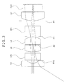
- Fig. 3 shows an optical arrangement, developed along the optical axis, of the objective optical system of a second embodiment in the present invention.
- the objective optical system of the second embodiment includes, in order from the object side, the negative meniscus lens L1 in which the object-side surface is flat and the image-side surface is concave, constructed as the first lens; the flare stop FS1; an infrared cutoff filter IF1; the plano-convex lens L2 in which the object-side surface is convex and the image-side surface is flat, constructed as the second lens; the aperture stop AS; the plano-convex lens L3 in which the object-side surface is flat and the image-side surface is convex, constructed as the third lens; the flare stop FS2; an infrared cutoff filter IF2; the flare stop FS3; a plano-convex lens L4 in which the object-side surface is convex and the image-side surface is flat, constructed as a fourth lens; and the CCD chip sealing glass CG2. Both surfaces of the infrared cutoff filter IF2 have YAG and LD laser light cutoff coatings.
- the fourth lens L4 is constructed so that it is placed in the proximity of the image plane to a grazing incidence sensitive characteristic of the image sensor to play the role of a field lens that controls the position of the exit pupil of the optical system.
- sapphire is used for the first lens L1; S-NPH2 (by OHARA INC.), for the second lens L2; S-YGH51 (by OHARA INC.), for the third lens L3; S-BSL7 (by OHARA INC.), for the fourth lens L4; and CM5000 (by HOYA CO.), for the infrared cutoff filters IF1 and IF2, as individual glass materials.
- the CCD chip sealing glass CG2 can also be constructed of the glass material that does not contain lead and arsenic.
- Each optical member may be constructed of some glass material that possesses optical properties equivalent to the above glass material.
- Fig. 4 shows an optical arrangement, developed along the optical axis, of the objective optical system of a third embodiment in the present invention.
- the objective optical system of the third embodiment includes, in order from the object side, the negative meniscus lens L1 in which the object-side surface is flat and the image-side surface is concave, constructed as the first lens; the flare stops FS1 and FS2; the plano-convex lens L2 in which the object-side surface is convex and the image-side surface is flat, constructed as the second lens; the aperture stop AS; the plano-convex lens L3 in which the object-side surface is flat and the image-side surface is convex, constructed as the third lens; the flare stop FS3; the infrared cutoff filter IF; flare stops FS4 and FS5; the plano-convex lens L4 in which the object-side surface is convex and the image-side surface is flat, constructed as the fourth lens; and the CCD chip sealing glass CG2. Both surfaces of the infrared cutoff filter IF have YAG and LD laser light cutoff coatings.
- the fourth lens L4 is constructed so that it is placed in the proximity of the image plane to a grazing incidence sensitive characteristic of the image sensor to play the role of a field lens that controls the position of the exit pupil of the optical system.
- sapphire is used for the first lens L1; S-NPH2 (by OHARA INC.), for the second lens L2; S-LAH66 (by OHARA INC.), for the third lens L3; S-LAH58 (by OHARA INC.), for the fourth lens L4; and CM5000 (by HOYA CO.), for the infrared cutoff filter IF, as individual glass materials.
- the CCD chip sealing glass CG2 can also be constructed of the glass material that does not contain lead and arsenic.
- Each optical member may be constructed of some glass material that possesses optical properties equivalent to the above glass material.
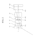
- Fig. 5 shows an optical arrangement, developed along the optical axis, of the objective optical system of a fourth embodiment in the present invention.
- the objective optical system of the fourth embodiment includes, in order from the object side, the negative meniscus lens L1 in which the object-side surface is flat and the image-side surface is concave, constructed as the first lens; the flare stop FS1; a filter F; the plano-convex lens L2 in which the object-side surface is convex and the image-side surface is flat, constructed as the second lens; the aperture stop AS; the plano-convex lens L3 in which the object-side surface is flat and the image-side surface is convex, constructed as the third lens; the flare stop FS2; the infrared cutoff filter IF; the flare stop FS3; the plano-convex lens L4 in which the object-side surface is convex and the image-side surface is flat, constructed as the fourth lens; and the CCD chip sealing glass CG2.
- Both surfaces of the filter F have YAG and LD laser light cutoff coatings.
- the fourth lens L4 is constructed so that it is placed in the proximity of the image plane to a grazing incidence sensitive characteristic of the image sensor to play the role of a field lens that controls the position of the exit pupil of the optical system.
- sapphire is used for the first lens L1; S-TIH53 (by OHARA INC.), for the second lens L2; S-LAL18 (by OHARA INC.), for the third lens L3; S-LAH58 (by OHARA INC.), for the fourth lens L4; B270-SUPERWITE (by SCHOTT DESAG AG), for the filter F; and CM5000 (by HOYA CO.), for the infrared cutoff filters IF, as individual glass materials.
- the CCD chip sealing glass CG2 can also be constructed of the glass material that does not contain lead and arsenic.
- Each optical member may be constructed of some glass material that possesses optical properties equivalent to the above glass material.
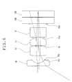
- Fig. 6 shows an optical arrangement, developed along the optical axis, of the objective optical system of a fifth embodiment in the present invention.
- the objective optical system of the fifth embodiment includes, in order from the object side, the negative meniscus lens L1 in which the object-side surface is flat and the image-side surface is concave, constructed as the first lens; the flare stops FS1 and FS2; a biconvex lens L2' constructed as the second lens; the aperture stop AS; the plano-convex lens L3 in which the object-side surface is flat and the image-side surface is convex, constructed as the third lens; the flare stop FS3; the infrared cutoff filter IF; the flare stop FS4; the CCD cover glass CG1; and the CCD chip sealing glass CG2. Both surfaces of the infrared cutoff filter IF have YAG and LD laser light cutoff coatings.
- GFK68 (by SUMITA Optical Glass Inc.) is used for the first lens L1; S-NPH2 (by OHARA INC.), for the second lens L2'; S-LAH58 (by OHARA INC.), for the third lens L3; C5000 (by HOYA CO.), for the infrared cutoff filter IF; and S-BSL7 (by OHARA INC.), for the CCD cover glass CG1, as individual glass materials.
- the CCD chip sealing glass CG2 can also be constructed of the glass material that does not contain lead and arsenic.
- Each optical member may be constructed of some glass material that possesses optical properties equivalent to the above glass material.
- the back focus of each of the first and fifth embodiments refers to the equivalent-air medium length from the image-side surface of the third lens to the position of the image focal point.
- the back focus refers to the equivalent-air medium length from the image-side surface of the third lens to the position of an image focal point.
- the objective lenses of individual embodiments ensure the back focuses 2.08 times (the first embodiment), 2.758 times (the second embodiment), 2.126 times (the third embodiment), 2.092 times (the fourth embodiment), and 2.073 time the focal lengths.
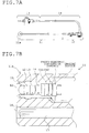
- FIGs. 7A and 7B illustrate one embodiment of an endoscope using the objective lens of the present invention.
- the endoscope of this embodiment has an insertion tube section 11 provided with the objective optical system of the present invention, a control section 12 for operating the insertion tube section 11, a joint section 13 for connecting an image display device and a light source, not shown, and a flexible universal cord section 14 connecting the control section 12 with the joint section 13.
- the distal end of the insertion tube section 11 is constructed as a hard portion 11a of rigidity. Inside the hard portion 11a, as illustrated in Fig. 7B, the objective lens of any of the embodiments is provided in a lens frame 15. Further, inside the hard portion 11a, an illumination lens 16 and a light guide 17 are encased.
- the endoscope of the embodiment since the objective lens of the present invention that is suitable for a small-sized image sensor with a high density of pixels and has a simple arrangement is used, the sleek design of the insertion tube section 11 is further achieved and the length of the hard portion 11a at the distal end can be reduced.
Landscapes
- Physics & Mathematics (AREA)
- General Physics & Mathematics (AREA)
- Optics & Photonics (AREA)
- Astronomy & Astrophysics (AREA)
- Lenses (AREA)
- Endoscopes (AREA)
Abstract
Description
- Patent Reference 1:
- Japanese Patent Kokai No. Hei 5-107470
- Patent Reference 2:
- Japanese Patent Kokai No. Hei 10-170821
- Patent Reference 3:
- Japanese Patent Kokai No. Hei 2-176611
| Name of glass material | S-NPH2 |
| Abbe's number (νd) | 18.9 |
| Glass code | 923189 |
| Manufactured by OHARA INC. |
| Numerical data 1 | ||||
| Face number | Radius of curvature | Face-to-face (or air) spacing | Refractive index | Abbe's number |
| 0 (Object surface) | ∞ | 10.6744 | ||
| 1 | ∞ | 0.3389 | 1.76820 | 71.79 |
| 2 | 0.8641 | 0.3389 | ||
| 3 | ∞ | 0.0508 | ||
| 4 | ∞ | 0.4744 | ||
| 5 | 2.7262 | 1.1013 | 1.92286 | 18.90 |
| 6 | ∞ | 0 | ||
| 7 (Stop) | ∞ | 0.0508 | ||
| 8 | ∞ | 0.8472 | 1.88300 | 40.76 |
| 9 | -1.4233 | 0 | ||
| 10 | ∞ | 0.0508 | ||
| 11 | ∞ | 1.0505 | 1.51400 | 75.00 |
| 12 | ∞ | 0.3897 | ||
| 13 | ∞ | 0.0508 | ||
| 14 | ∞ | 0.6777 | 1.51633 | 64.14 |
| 15 | ∞ | 0.0169 | 1.51000 | 64.10 |
| 16 | ∞ | 0.6777 | 1.52000 | 64.10 |
| 17 | ∞ | 0 | ||
| 18 (Imaging surface) | ∞ | 0 |
| Numerical data 2 | ||||
| Face number | Radius of curvature | Face-to-face (or air) spacing | Refractive index | Abbe's number |
| 0 (Object surface) | ∞ | 10.1769 | ||
| 1 | ∞ | 0.3769 | 1.76820 | 71.79 |
| 2 | 0.8481 | 0.2827 | ||
| 3 | ∞ | 0.0565 | ||
| 4 | ∞ | 0.7538 | 1.49400 | 75.00 |
| 5 | ∞ | 0.1508 | ||
| 6 | 2.8684 | 0.7350 | 1.92286 | 18.90 |
| 7 | ∞ | 0 | ||
| 8 (Stop) | ∞ | 0.0565 | ||
| 9 | ∞ | 0.8292 | 1.75500 | 52.32 |
| 10 | -1.5152 | 0.0565 | ||
| 11 | ∞ | 0 | ||
| 12 | ∞ | 1.1308 | 1.49400 | 75.00 |
| 13 | ∞ | 0.5654 | ||
| 14 | ∞ | 0 | ||
| 15 | 2.6234 | 0.9423 | 1.51633 | 64.14 |
| 16 | ∞ | 0.0188 | 1.51000 | 64.14 |
| 17 | ∞ | 0.7538 | 1.61350 | 50.20 |
| 18 | ∞ | 0.0188 | 1.51000 | 64.14 |
| 19 | ∞ | 0 | ||
| 20 (Imaging surface) | ∞ | 0 |
| Numerical data 3 | ||||
| Face number | Radius of curvature | Face-to-face (or air) spacing | Refractive index | Abbe's number |
| 0 (Object surface) | ∞ | 10.0657 | ||
| 1 | ∞ | 0.2013 | 1.76820 | 71.79 |
| 2 | 0.7449 | 0.3020 | ||
| 3 | ∞ | 0.0302 | ||
| 4 | ∞ | 0.0805 | ||
| 5 | 2.5678 | 0.4228 | 1.92286 | 18.90 |
| 6 | ∞ | 0.4026 | ||
| 7 (stop) | ∞ | 0.0302 | ||
| 8 | ∞ | 0.6140 | 1.77250 | 49.60 |
| 9 | -1.0478 | 0.0201 | ||
| 10 | ∞ | 0.0302 | ||
| 11 | ∞ | 1.0066 | 1.49400 | 75.00 |
| 12 | ∞ | 0.6241 | ||
| 13 | ∞ | 0.0302 | ||
| 14 | ∞ | 0.1007 | ||
| 15 | 6.0978 | 0.6845 | 1.88300 | 40.76 |
| 16 | ∞ | 0.0101 | 1.51000 | 63.80 |
| 17 | ∞ | 0.4026 | 1.61090 | 50.20 |
| 18 | ∞ | 0 | ||
| 19 (Imaging surface) | ∞ | 0 |
| Numerical data 4 | ||||
| Face number | Radius of curvature | Face-to-face (or air) spacing | Refractive index | Abbe's number |
| 0 (Object surface) | ∞ | 9.3606 | ||
| 1 | ∞ | 0.2080 | 1.76820 | 71.79 |
| 2 | 0.7696 | 0.3432 | ||
| 3 | ∞ | 0.1352 | ||
| 4 | ∞ | 0.4160 | 1.52287 | 59.89 |
| 5 | ∞ | 0.0416 | ||
| 6 | 1.7650 | 0.7072 | 1.84666 | 23.78 |
| 7 | ∞ | 0.1040 | ||
| 8 (Stop) | ∞ | 0.0312 | ||
| 9 | ∞ | 0.5512 | 1.72916 | 54.68 |
| 10 | -1.3240 | 0.0208 | ||
| 11 | ∞ | 0.0312 | ||
| 12 | ∞ | 1.0401 | 1.49400 | 75.00 |
| 13 | ∞ | 0.6240 | ||
| 14 | ∞ | 0.0312 | ||
| 15 | 6.3007 | 0.7072 | 1.88300 | 40.76 |
| 16 | ∞ | 0.0104 | 1.56384 | 60.70 |
| 17 | ∞ | 0.4160 | 1.51100 | 64.14 |
| 18 | ∞ | 0.0088 | 1.56384 | 60.70 |
| 19 | ∞ | 0 | ||
| 20 (Imaging surface) | ∞ | 0 |
| Numerical data 5 | ||||
| Face number | Radius of curvature | Face-to-face (or air) spacing | Refractive index | Abbe's number |
| 0 (Object surface) | ∞ | 10.7814 | ||
| 1 | ∞ | 0.3082 | 1.59240 | 68.33 |
| 2 | 0.7482 | 0.3423 | ||
| 3 | ∞ | 0.0513 | ||
| 4 | ∞ | 0.4055 | ||
| 5 | 4.6335 | 1.1124 | 1.92286 | 18.90 |
| 6 | -18.7952 | 0 | ||
| 7 (Stop) | ∞ | 0.0513 | ||
| 8 | 42.1769 | 0.8557 | 1.88300 | 40.76 |
| 9 | -1.3733 | 0 | ||
| 10 | ∞ | 0.0513 | ||
| 11 | ∞ | 1.0610 | 1.51400 | 75.00 |
| 12 | ∞ | 0.3765 | ||
| 13 | ∞ | 0.0513 | ||
| 14 | ∞ | 0.6845 | 1.51633 | 64.14 |
| 15 | ∞ | 0.0171 | 1.51000 | 64.10 |
| 16 | ∞ | 0.6845 | 1.52000 | 64.10 |
| 17 | ∞ | 0 | ||
| 18 (Imaging surface) | ∞ | 0 |
| Condition | First embodiment | Second embodiment | Third embodiment | Fourth embodiment | Fifth embodiment |
| 45 < νd1 - νd2 | 52.89 | 52.89 | 52.89 | 48.01 | 49.43 |
| -0.6 < f1 / f2 < -0.3 | -0.381 | -0.355 | -0.348 | -0.481 | -0.306 |
| 0<{1/(νd1×f1)+1/(νd2×f2)}×f<0.02 | 0.006 | 0.004 | 0.005 | 0.006 | 0.001 |
| νd2<20 | 18.90 | 18.90 | 18.90 | 23.78 | 18.90 |
| Condition parameters | First embodiment | Second embodiment | Third embodiment | Fourth embodiment | Fifth embodiment |
| f | 1.000 | 1.000 | 1.000 | 1.000 | 1.000 |
| f1 | -1.125 | -1.104 | -0.970 | -1.002 | -1.263 |
| f2 | 2.956 | 3.105 | 2.783 | 2.085 | 4.122 |
| νd1 | 71.79 | 71.79 | 71.79 | 71.79 | 68.33 |
| Other specifications | First embodiment | Second embodiment | Third embodiment | Fourth embodiment | Fifth embodiment |
| F-number | 4.604 | 4.153 | 4.623 | 5.023 | 4.484 |
| Image height | 0.898 | 0.901 | 0.917 | 0.927 | 0.907 |
| Total angle of view | 115.4 | 116.3 | 117.5 | 116.7 | 115.7 |
| Object distance | 10.6744 | 10.1769 | 10.0657 | 9.3606 | 10.7814 |
| Chromatic aberration of magnification at maximum angle of view | 0.006 | 0.009 | 0.006 | 0.005 | 0.009 |
| Back focus | 2.080 | 2.758 | 2.126 | 2.092 | 2.073 |
| First lens medium | Sapphire | Sapphire | Sapphire | Sapphire | GFK68 |
| Second lens medium | S-NPH2 | S-NPH2 | S-NPH2 | S-TIH53 | S-NPH2 |
- L1
- First lens (negative meniscus lens in which the object-side surface is flat and the image-side surface is concave)
- L2
- Second lens (plano-convex lens in which the object-side surface is convex and the image-side surface is flat)
- L3
- Third lens (plano-convex lens in which the object-side surface is flat and the image-side surface is convex)
- L4
- Fourth lens (plano-convex lens in which the object-side surface is convex and the image-side surface is flat)
- FS1, FS2, FS3, and FS4
- Flare stops
- AS
- Aperture stop
- IF, IF1, and IF2
- Infrared cutoff filters
- CG1
- CCD cover glass
- CG2
- CCD chip sealing glass
- 11
- Endoscope insertion tube section
- 11a
- Distal end hard portion
- 12
- Control section
- 13
- Joint section
- 14
- Universal cord section
- 15
- Lens frame
- 16
- Illumination lens
- 17
- Light guide
Claims (19)
- An objective lens comprising, in order from an object side:characterized in that a lens component located on the image side of the aperture stop (AS) is constructed with a positive single lens or a plurality of positive single lenses and the objective lens satisfies the following conditions:a first lens (L1) with negative power;a second lens (L2, L2') with positive power;an aperture stop (AS); anda third lens (L3) with positive power,
- An objective lens according to claim 1, characterized by satisfying the following condition:
- An endoscope using an objective lens, the objective lens comprising, in order from an object side:characterized in that a lens component located on the image side of the aperture stop (AS) is constructed with a positive single lens or a plurality of positive single lenses and the objective lens satisfies the following conditions:a first lens (L1) with negative power;a second lens (L2, L2') with positive power;an aperture stop (AS); anda third lens (L3) with positive power,
- An objective lens according to claim 1, characterized in that the first lens (L1) is constructed of sapphire.
- An objective lens according to claim 1, characterized in that the lens is constructed of material excluding optically unfavorable substances, such as lead and arsenic.
- An objective optical system comprising, in order from an object side:characterized in that a lens component located on the image side of the aperture stop (AS) is constructed with a positive single lens or a plurality of positive single lenses and the objective optical system satisfies the following conditions:a first lens (L1) with negative power;a second lens (L2, L2') with positive power;an aperture stop (AS); anda third lens (L3) with positive power,
- An endoscope using an objective lens, the objective lens comprising, in order from an object side:characterized in that a lens component located on the image side of the aperture stop (AS) is constructed with a positive single lens or a plurality of positive single lenses and the objective lens satisfies the following conditions:a first lens (L1) with negative power;a second lens (L2, L2') with positive power;an aperture stop (AS); anda third lens (L3) with positive power,
- An objective lens according to claim 6, characterized in that the first lens (AS) is constructed of sapphire.
- An objective lens according to claim 6, characterized in that the lens is constructed of material excluding optically unfavorable substances, such as lead and arsenic.
- An objective lens comprising, in order from an object side:characterized in that the objective lens satisfies the following conditions:a first lens (L1) with negative power;a second lens (L2, L2') with positive power;an aperture stop (AS); anda third lens (L3) with positive power,
- An objective lens according to claim 10, characterized by satisfying the following condition:
- An endoscope using an objective lens, the objective lens comprising, in order from an object side:where νd1 is an Abbe's number of the first lens, νd2 is an Abbe's number of the second lens, f1 is a focal length of the first lens, f2 is a focal length of the second lens, and f is a focal length of an entire system of the objective lens.a first lens (L1) with negative power;a second lens (L2, L2') with positive power;an aperture stop (AS); anda third lens (L3) with positive power,characterizes in that the objective lens satisfies the following conditions:
- An objective lens according to claim 10, characterized in that the first lens (L1) is constructed of sapphire.
- An objective lens according to claim 10, characterized in that the lens is constructed of material excluding optically unfavorable substances, such as lead and arsenic.
- An objective lens comprising, in order from an object side:characterized in that the objective lens satisfies the following conditions:a first lens (L1) with negative power;a second lens (L2) with positive power;an aperture stop (AS);a third lens (L3) with positive power; anda fourth lens (L4) with positive power, placed in the proximity of an image plane,
- An objective lens according to claim 15, characterized by satisfying the following condition:
- An endoscope using an objective lens, the objective lens comprising, in order from an object side:characterized in that the objective lens satisfies the following conditions:a first lens (L1) with negative power;a second lens (L2) with positive power;an aperture stop (AS);a third lens (L3) with positive power; anda fourth lens (L4) with positive power, placed in the proximity of an image plane,
- An objective lens according to claim 15, characterized in that the first lens (L1) is constructed of sapphire.
- An objective lens according to claim 15, characterized in that the lens is constructed of material excluding optically unfavorable substances, such as lead and arsenic.
Applications Claiming Priority (3)
| Application Number | Priority Date | Filing Date | Title |
|---|---|---|---|
| JP2003137263 | 2003-05-15 | ||
| JP2003137263A JP4229754B2 (en) | 2003-05-15 | 2003-05-15 | Objective lens and endoscope using the same |
| PCT/JP2004/006533 WO2004102247A1 (en) | 2003-05-15 | 2004-05-14 | Object lens and endoscope using it |
Publications (3)
| Publication Number | Publication Date |
|---|---|
| EP1526398A1 true EP1526398A1 (en) | 2005-04-27 |
| EP1526398A4 EP1526398A4 (en) | 2005-09-21 |
| EP1526398B1 EP1526398B1 (en) | 2012-03-14 |
Family
ID=33447250
Family Applications (1)
| Application Number | Title | Priority Date | Filing Date |
|---|---|---|---|
| EP04733081A Expired - Lifetime EP1526398B1 (en) | 2003-05-15 | 2004-05-14 | Endoscope with an objective lens |
Country Status (4)
| Country | Link |
|---|---|
| US (1) | US7085064B2 (en) |
| EP (1) | EP1526398B1 (en) |
| JP (1) | JP4229754B2 (en) |
| WO (1) | WO2004102247A1 (en) |
Cited By (6)
| Publication number | Priority date | Publication date | Assignee | Title |
|---|---|---|---|---|
| EP1980893A3 (en) * | 2007-04-13 | 2008-11-26 | Karl Storz Imaging Inc. | Objective lens design for miniature endoscope |
| EP2390685A4 (en) * | 2009-03-09 | 2012-09-26 | Olympus Medical Systems Corp | METHOD FOR MANUFACTURING A MONOCRYSTAL OPTICAL LENS |
| US8531781B2 (en) | 2009-09-01 | 2013-09-10 | Olympus Medical Systems Corp. | Objective optical system |
| EP2851727A4 (en) * | 2012-05-17 | 2016-02-17 | Olympus Corp | OPTICAL ENDOSCOPE OBJECTIVE ASSEMBLY |
| EP3321722A4 (en) * | 2016-02-23 | 2019-02-27 | HOYA Corporation | VARIABLE MAGNIFICATION OPTICAL SYSTEM FOR ENDOSCOPE, AND ENDOSCOPE |
| US10831001B2 (en) | 2016-05-12 | 2020-11-10 | Nalux Co., Ltd. | Imaging optical system |
Families Citing this family (61)
| Publication number | Priority date | Publication date | Assignee | Title |
|---|---|---|---|---|
| US20050245789A1 (en) | 2003-04-01 | 2005-11-03 | Boston Scientific Scimed, Inc. | Fluid manifold for endoscope system |
| US7578786B2 (en) | 2003-04-01 | 2009-08-25 | Boston Scientific Scimed, Inc. | Video endoscope |
| US7591783B2 (en) * | 2003-04-01 | 2009-09-22 | Boston Scientific Scimed, Inc. | Articulation joint for video endoscope |
| US20040199052A1 (en) | 2003-04-01 | 2004-10-07 | Scimed Life Systems, Inc. | Endoscopic imaging system |
| US8118732B2 (en) | 2003-04-01 | 2012-02-21 | Boston Scientific Scimed, Inc. | Force feedback control system for video endoscope |
| US7597662B2 (en) | 2004-09-30 | 2009-10-06 | Boston Scientific Scimed, Inc. | Multi-fluid delivery system |
| US7479106B2 (en) | 2004-09-30 | 2009-01-20 | Boston Scientific Scimed, Inc. | Automated control of irrigation and aspiration in a single-use endoscope |
| US8083671B2 (en) | 2004-09-30 | 2011-12-27 | Boston Scientific Scimed, Inc. | Fluid delivery system for use with an endoscope |
| US8199187B2 (en) | 2004-09-30 | 2012-06-12 | Boston Scientific Scimed, Inc. | Adapter for use with digital imaging medical device |
| US7574096B2 (en) * | 2006-04-10 | 2009-08-11 | Lightconnect, Inc. | Optical attenuator |
| US7955255B2 (en) | 2006-04-20 | 2011-06-07 | Boston Scientific Scimed, Inc. | Imaging assembly with transparent distal cap |
| US8202265B2 (en) | 2006-04-20 | 2012-06-19 | Boston Scientific Scimed, Inc. | Multiple lumen assembly for use in endoscopes or other medical devices |
| JP2009288682A (en) * | 2008-05-30 | 2009-12-10 | Olympus Medical Systems Corp | Objective optical system for endoscopes |
| US8926502B2 (en) | 2011-03-07 | 2015-01-06 | Endochoice, Inc. | Multi camera endoscope having a side service channel |
| US9101287B2 (en) | 2011-03-07 | 2015-08-11 | Endochoice Innovation Center Ltd. | Multi camera endoscope assembly having multiple working channels |
| US9492063B2 (en) | 2009-06-18 | 2016-11-15 | Endochoice Innovation Center Ltd. | Multi-viewing element endoscope |
| US11547275B2 (en) | 2009-06-18 | 2023-01-10 | Endochoice, Inc. | Compact multi-viewing element endoscope system |
| US9642513B2 (en) | 2009-06-18 | 2017-05-09 | Endochoice Inc. | Compact multi-viewing element endoscope system |
| US9706903B2 (en) | 2009-06-18 | 2017-07-18 | Endochoice, Inc. | Multiple viewing elements endoscope system with modular imaging units |
| US9713417B2 (en) | 2009-06-18 | 2017-07-25 | Endochoice, Inc. | Image capture assembly for use in a multi-viewing elements endoscope |
| US10165929B2 (en) | 2009-06-18 | 2019-01-01 | Endochoice, Inc. | Compact multi-viewing element endoscope system |
| US9402533B2 (en) | 2011-03-07 | 2016-08-02 | Endochoice Innovation Center Ltd. | Endoscope circuit board assembly |
| US12137873B2 (en) | 2009-06-18 | 2024-11-12 | Endochoice, Inc. | Compact multi-viewing element endoscope system |
| EP2442706B1 (en) | 2009-06-18 | 2014-11-12 | EndoChoice Innovation Center Ltd. | Multi-camera endoscope |
| US11864734B2 (en) | 2009-06-18 | 2024-01-09 | Endochoice, Inc. | Multi-camera endoscope |
| US11278190B2 (en) | 2009-06-18 | 2022-03-22 | Endochoice, Inc. | Multi-viewing element endoscope |
| US9872609B2 (en) | 2009-06-18 | 2018-01-23 | Endochoice Innovation Center Ltd. | Multi-camera endoscope |
| US9901244B2 (en) | 2009-06-18 | 2018-02-27 | Endochoice, Inc. | Circuit board assembly of a multiple viewing elements endoscope |
| US9101268B2 (en) | 2009-06-18 | 2015-08-11 | Endochoice Innovation Center Ltd. | Multi-camera endoscope |
| WO2012077116A1 (en) | 2010-12-09 | 2012-06-14 | Peermedical Ltd. | Flexible electronic circuit board for a multi-camera endoscope |
| WO2011077972A1 (en) | 2009-12-24 | 2011-06-30 | オリンパスメディカルシステムズ株式会社 | Objective lens for endoscope, and endoscope using same |
| US12220105B2 (en) | 2010-06-16 | 2025-02-11 | Endochoice, Inc. | Circuit board assembly of a multiple viewing elements endoscope |
| US8218254B2 (en) | 2010-08-23 | 2012-07-10 | Gyrus Acmi, Inc. | Solid imaging objective and assembly technique for small scale sensor applications |
| EP4233680B1 (en) | 2010-09-20 | 2025-06-18 | EndoChoice, Inc. | Endoscope distal section comprising a unitary fluid channeling component |
| US9560953B2 (en) | 2010-09-20 | 2017-02-07 | Endochoice, Inc. | Operational interface in a multi-viewing element endoscope |
| EP2635932B1 (en) | 2010-10-28 | 2019-06-05 | EndoChoice Innovation Center Ltd. | Optical systems for multi-sensor endoscopes |
| US12204087B2 (en) | 2010-10-28 | 2025-01-21 | Endochoice, Inc. | Optical systems for multi-sensor endoscopes |
| EP3420886B8 (en) | 2010-12-09 | 2020-07-15 | EndoChoice, Inc. | Flexible electronic circuit board multi-camera endoscope |
| US11889986B2 (en) | 2010-12-09 | 2024-02-06 | Endochoice, Inc. | Flexible electronic circuit board for a multi-camera endoscope |
| CN103491854B (en) | 2011-02-07 | 2016-08-24 | 恩多卓斯创新中心有限公司 | Multicomponent cover for many cameras endoscope |
| JP5687572B2 (en) * | 2011-06-14 | 2015-03-18 | オリンパス株式会社 | Imaging optical system and endoscope apparatus including the same |
| CA2798729A1 (en) | 2011-12-13 | 2013-06-13 | Peermedical Ltd. | Rotatable connector for an endoscope |
| CA2798716A1 (en) | 2011-12-13 | 2013-06-13 | Endochoice Innovation Center Ltd. | Removable tip endoscope |
| US9560954B2 (en) | 2012-07-24 | 2017-02-07 | Endochoice, Inc. | Connector for use with endoscope |
| WO2014054407A1 (en) * | 2012-10-02 | 2014-04-10 | オリンパスメディカルシステムズ株式会社 | Endoscope objective optical system |
| US9993142B2 (en) | 2013-03-28 | 2018-06-12 | Endochoice, Inc. | Fluid distribution device for a multiple viewing elements endoscope |
| US9986899B2 (en) | 2013-03-28 | 2018-06-05 | Endochoice, Inc. | Manifold for a multiple viewing elements endoscope |
| US10499794B2 (en) | 2013-05-09 | 2019-12-10 | Endochoice, Inc. | Operational interface in a multi-viewing element endoscope |
| CN104656242B (en) * | 2013-11-22 | 2016-10-05 | 深圳先进技术研究院 | Endoscope's binocular optical system of doublet single image sensor |
| JP2016031501A (en) * | 2014-07-30 | 2016-03-07 | 日立マクセル株式会社 | Imaging lens system and imaging apparatus |
| TWI548894B (en) | 2015-02-04 | 2016-09-11 | 大立光電股份有限公司 | Optical lens assembly and image capturing device |
| WO2017060950A1 (en) * | 2015-10-05 | 2017-04-13 | オリンパス株式会社 | Imaging device and optical device comprising same |
| WO2017068726A1 (en) * | 2015-10-23 | 2017-04-27 | オリンパス株式会社 | Imaging device and optical device provided with same |
| JP2018112677A (en) * | 2017-01-12 | 2018-07-19 | ソニーセミコンダクタソリューションズ株式会社 | Imaging unit and electronic device |
| CN109951619A (en) * | 2019-02-26 | 2019-06-28 | 武汉华星光电半导体显示技术有限公司 | display device |
| TWI689746B (en) | 2019-03-22 | 2020-04-01 | 大立光電股份有限公司 | Optical imaging system, image capturing unit and electronic device |
| DE102019008226A1 (en) * | 2019-11-26 | 2021-05-27 | Karl Storz Se & Co. Kg | Lens system for a video endoscope, endoscope lens, video endoscope, and assembly process |
| TWI730517B (en) | 2019-11-29 | 2021-06-11 | 大立光電股份有限公司 | Lens system and electronic device |
| CN112882211B (en) * | 2021-01-18 | 2021-12-07 | 广东烨嘉光电科技股份有限公司 | Large-aperture four-piece optical lens |
| JP7844174B2 (en) * | 2022-02-01 | 2026-04-13 | キヤノン株式会社 | Optical system and imaging device |
| CN116088162A (en) * | 2023-02-20 | 2023-05-09 | 北京华信佳音医疗科技发展有限责任公司 | Objective lens device for endoscope |
Family Cites Families (12)
| Publication number | Priority date | Publication date | Assignee | Title |
|---|---|---|---|---|
| JPH07122692B2 (en) * | 1988-09-29 | 1995-12-25 | 富士写真光機株式会社 | Objective lens for endoscope |
| JP3206930B2 (en) * | 1991-05-13 | 2001-09-10 | オリンパス光学工業株式会社 | Endoscope objective lens |
| US5223982A (en) * | 1991-03-05 | 1993-06-29 | Olympus Optical Co., Ltd. | Objective lens system for endoscopes |
| JP3353910B2 (en) * | 1992-04-15 | 2002-12-09 | オリンパス光学工業株式会社 | Objective optical system for rigid endoscope |
| US5805359A (en) * | 1995-05-19 | 1998-09-08 | Olympus Optical Co., Ltd. | Wide-angle lens system |
| JP3441567B2 (en) * | 1995-08-21 | 2003-09-02 | ペンタックス株式会社 | Endoscope objective lens |
| JPH10170821A (en) | 1996-12-16 | 1998-06-26 | Olympus Optical Co Ltd | Objective lens for endoscope |
| JPH1164726A (en) * | 1997-08-22 | 1999-03-05 | Olympus Optical Co Ltd | Wide-angle lens |
| US6236521B1 (en) * | 1998-02-09 | 2001-05-22 | Canon Kabushiki Kaisha | Objective lens and image pickup device using the same |
| JPH11271607A (en) * | 1998-03-19 | 1999-10-08 | Olympus Optical Co Ltd | Small-sized image pickup optical system |
| JP2000330015A (en) * | 1999-03-12 | 2000-11-30 | Fuji Photo Optical Co Ltd | Variable observation depth objective lens for endoscopes |
| JP4556382B2 (en) * | 2002-08-26 | 2010-10-06 | コニカミノルタオプト株式会社 | Wide angle lens |
-
2003
- 2003-05-15 JP JP2003137263A patent/JP4229754B2/en not_active Expired - Fee Related
-
2004
- 2004-05-14 EP EP04733081A patent/EP1526398B1/en not_active Expired - Lifetime
- 2004-05-14 US US10/513,120 patent/US7085064B2/en not_active Expired - Lifetime
- 2004-05-14 WO PCT/JP2004/006533 patent/WO2004102247A1/en not_active Ceased
Cited By (10)
| Publication number | Priority date | Publication date | Assignee | Title |
|---|---|---|---|---|
| EP1980893A3 (en) * | 2007-04-13 | 2008-11-26 | Karl Storz Imaging Inc. | Objective lens design for miniature endoscope |
| EP2105780A1 (en) * | 2007-04-13 | 2009-09-30 | Karl Storz Imaging Inc. | Objective lens design for miniature endoscope |
| US7869140B2 (en) | 2007-04-13 | 2011-01-11 | Karl Storz Imaging, Inc. | Objective lens design for miniature endoscope |
| EP2328010A1 (en) * | 2007-04-13 | 2011-06-01 | Karl Storz Imaging Inc. | Objective lens design for miniature endoscope |
| US8724236B2 (en) | 2007-04-13 | 2014-05-13 | Karl Storz Imaging, Inc. | Objective lens design for miniature endoscope |
| EP2390685A4 (en) * | 2009-03-09 | 2012-09-26 | Olympus Medical Systems Corp | METHOD FOR MANUFACTURING A MONOCRYSTAL OPTICAL LENS |
| US8531781B2 (en) | 2009-09-01 | 2013-09-10 | Olympus Medical Systems Corp. | Objective optical system |
| EP2851727A4 (en) * | 2012-05-17 | 2016-02-17 | Olympus Corp | OPTICAL ENDOSCOPE OBJECTIVE ASSEMBLY |
| EP3321722A4 (en) * | 2016-02-23 | 2019-02-27 | HOYA Corporation | VARIABLE MAGNIFICATION OPTICAL SYSTEM FOR ENDOSCOPE, AND ENDOSCOPE |
| US10831001B2 (en) | 2016-05-12 | 2020-11-10 | Nalux Co., Ltd. | Imaging optical system |
Also Published As
| Publication number | Publication date |
|---|---|
| US20050225872A1 (en) | 2005-10-13 |
| EP1526398A4 (en) | 2005-09-21 |
| EP1526398B1 (en) | 2012-03-14 |
| JP4229754B2 (en) | 2009-02-25 |
| WO2004102247A1 (en) | 2004-11-25 |
| JP2004337346A (en) | 2004-12-02 |
| US7085064B2 (en) | 2006-08-01 |
Similar Documents
| Publication | Publication Date | Title |
|---|---|---|
| EP1526398B1 (en) | Endoscope with an objective lens | |
| US5999327A (en) | Objective lens system | |
| JP3765500B2 (en) | Endoscope objective lens | |
| JP2920670B2 (en) | Endoscope objective lens | |
| JP3559623B2 (en) | Imaging lens | |
| JP2876252B2 (en) | Endoscope objective lens | |
| US20090109548A1 (en) | Zoom lens and image-pickup apparatus | |
| JP5374667B1 (en) | Endoscope objective optical system | |
| JPH11316339A (en) | Objective optical system | |
| JPWO2011077972A1 (en) | Endoscope objective lens and endoscope using the same | |
| CN107111112B (en) | Objective optical system for endoscope | |
| JP2017068164A (en) | Wide-angle optical system and imaging apparatus including the same | |
| WO2014155821A1 (en) | Optical system for endoscope | |
| JPH07318799A (en) | Endoscope objective optical system | |
| JP4634578B2 (en) | Endoscope objective variable magnification optical system | |
| JP6865303B2 (en) | Endoscope objective optical system, endoscope imaging device and endoscope | |
| US20230152565A1 (en) | Microscope objective lens, microscope device, and microscope optical system | |
| JPH0961710A (en) | Endoscope objective lens | |
| JPH10288736A (en) | Endoscope objective lens system | |
| JP3140841B2 (en) | Objective optical system for endoscope | |
| JPH0968648A (en) | Endoscope objective lens | |
| JP3574484B2 (en) | Objective optical system for endoscope | |
| CN107076965A (en) | Endoscope objective optical system | |
| JP4814746B2 (en) | Endoscope objective optical system | |
| CN114600026A (en) | Objective optical system for endoscope and endoscope |
Legal Events
| Date | Code | Title | Description |
|---|---|---|---|
| PUAI | Public reference made under article 153(3) epc to a published international application that has entered the european phase |
Free format text: ORIGINAL CODE: 0009012 |
|
| 17P | Request for examination filed |
Effective date: 20041111 |
|
| AK | Designated contracting states |
Kind code of ref document: A1 Designated state(s): AT BE BG CH CY CZ DE DK EE ES FI FR GB GR HU IE IT LI LU MC NL PL PT RO SE SI SK TR |
|
| AX | Request for extension of the european patent |
Extension state: AL HR LT LV MK |
|
| A4 | Supplementary search report drawn up and despatched |
Effective date: 20050804 |
|
| DAX | Request for extension of the european patent (deleted) | ||
| RBV | Designated contracting states (corrected) |
Designated state(s): DE FR |
|
| 17Q | First examination report despatched |
Effective date: 20090325 |
|
| REG | Reference to a national code |
Ref country code: DE Ref legal event code: R079 Ref document number: 602004036896 Country of ref document: DE Free format text: PREVIOUS MAIN CLASS: G02B0013040000 Ipc: G02B0023240000 |
|
| GRAP | Despatch of communication of intention to grant a patent |
Free format text: ORIGINAL CODE: EPIDOSNIGR1 |
|
| RIC1 | Information provided on ipc code assigned before grant |
Ipc: G02B 9/12 20060101ALI20110928BHEP Ipc: G02B 13/04 20060101ALI20110928BHEP Ipc: G02B 23/24 20060101AFI20110928BHEP Ipc: G02B 9/34 20060101ALI20110928BHEP |
|
| RTI1 | Title (correction) |
Free format text: ENDOSCOPE WITH AN OBJECTIVE LENS |
|
| GRAS | Grant fee paid |
Free format text: ORIGINAL CODE: EPIDOSNIGR3 |
|
| GRAA | (expected) grant |
Free format text: ORIGINAL CODE: 0009210 |
|
| AK | Designated contracting states |
Kind code of ref document: B1 Designated state(s): DE FR |
|
| REG | Reference to a national code |
Ref country code: DE Ref legal event code: R096 Ref document number: 602004036896 Country of ref document: DE Effective date: 20120510 |
|
| PLBE | No opposition filed within time limit |
Free format text: ORIGINAL CODE: 0009261 |
|
| STAA | Information on the status of an ep patent application or granted ep patent |
Free format text: STATUS: NO OPPOSITION FILED WITHIN TIME LIMIT |
|
| 26N | No opposition filed |
Effective date: 20121217 |
|
| REG | Reference to a national code |
Ref country code: FR Ref legal event code: ST Effective date: 20130131 |
|
| REG | Reference to a national code |
Ref country code: DE Ref legal event code: R097 Ref document number: 602004036896 Country of ref document: DE Effective date: 20121217 |
|
| PG25 | Lapsed in a contracting state [announced via postgrant information from national office to epo] |
Ref country code: FR Free format text: LAPSE BECAUSE OF NON-PAYMENT OF DUE FEES Effective date: 20120531 |
|
| P01 | Opt-out of the competence of the unified patent court (upc) registered |
Effective date: 20230528 |
|
| PGFP | Annual fee paid to national office [announced via postgrant information from national office to epo] |
Ref country code: DE Payment date: 20230519 Year of fee payment: 20 |
|
| REG | Reference to a national code |
Ref country code: DE Ref legal event code: R071 Ref document number: 602004036896 Country of ref document: DE |